Embed Size (px)
Citation preview

OPERATION MANUAL Please read this Operation Manual carefully before use, and file for future reference.
OM-E0232E 003
Automatic Handpiece Cleaning & Lubrication System

Explains an instruction where death or serious injury may occur.
Safety CautionsRead these safety precautions before use and operate the product in accordance with this Operation Manual.
The indicators are designed to allow you to use the product safely and prevent danger and harm to you and others. These
indicators are classified by degree of danger, damage and seriousness. All indicators concern safety and you must ensure
that they are strictly followed at all times.
Explains an instruction where personal injury or damage to device may occur.
Explains an instruction where the possibility of minor to medium personal injury or damage
to device may exist.
DANGER
Degree of Danger or Damage and SeriousnessClassification
WARNING
CAUTION
· Do not install, use this product or fill it with Maintenance Oil in a room with a risk of explosion or near open flames.
· Do not install or use the product in direct sunlight or where the temperature exceeds 40 °C (104 °F).
· Do not use this product for purposes other than the maintenance (cleaning and lubrication) of instruments described in
this Operating Manual.
· Provide adequate ventilation. If odours cause you concern provide additional ventilation immediately.
DANGER
· Do not handle the Power Cord with wet hands as this may result in an electric shock.
· Be careful not to spill water onto the Control Unit as this may result in a fire or an electric shock due to a short-circuit.
· Do not disassemble or alter the Control Unit. For service or repair contact your authorised dealer.
· If the Control Unit smokes or smells of burning, turn off the power immediate and disconnect the power plug. Contact
your dealer.
· Do not drop the Control Unit. Place the Control Unit on a flat surface.
· Use a Fuse of specified rating. (120V: T800mAL 250V, 220V/240V: T400mAH 250V)
WARNING
1
· If blood infiltrates into an Implant or Surgical handpiece, cleaning is difficult in Care3 plus. In this case, clean in PANA
SPRAY plus/PANA SPRAY.
· Do not clean Air Scaler or Phatelus Air Motor by using Care3 plus. Care3 plus cleaning method is improper to those
structures.
· Always autoclave handpieces after cleaning and lubricating with this product.
· The system functions normally in an environment where the temperature is at 10- 40°C ( 50-104°F ), humidity at
25-70% RH and no moisture condensation in the Control Unit. Use at outside these limits may cause malfunction.
· Store the system in a place where the temperature is at -10-50°C ( 14-122°F ), humidity at 10-85% RH, atmospheric
pressure at 500-1060 hPa and the Unit is not subject to air with dust, sulfur or salinity.
· When installing this product, provide space of approximately 10 cm around the Control Unit.
· Place a collector such as a tray under the Control Unit.
· After use, immediately turn off the Power Switch and shut off the air supply.
· Equipment to be sent back to manufacturer for servicing / repair.
CAUTION
Thank you for purchasing the Care3 Plus. This product is designed to clean and lubricate the handpiece easily and
thouroughly. Please read this Operation Manual carefully before use and file for future reference.

· Do not place equipment so that it is difficult to pull out power supply cord from rear side receptacle.
· Only use with original power supply cord. In case of damage, contact NSK / Nakanishi servicing center.
· The air supply to this device (Air Compressor etc.) and Air Filter need to be clean and free from moisture. Drain the Air
Compressor and Air Filter at least once a week. Moisture from the tank could mix with the Maintenance Oil and defeat
the purpose of this device.
· Remove the Air Tube and the Power Cord if the Control Unit is not to be used for a long time.
· When storing the Maintenance Oil keep away from strong oxidizing agents, combustible materials and strong acid
chemicals.
· The user shall be responsible for operation, maintenance.
· Only purchase original NSK replacement parts such as Maintenance Oil (Refer to accessories list). Any parts other than
original NSK accessories could cause damage and malfunction.
2
· Choice of 4 connectors according to individual needs.
C0 type : E-type = 0 pce. Air turbine = 3 pcs.
C1 type : E-type = 1 pce. Air turbine = 2 pcs.
C2 type : E-type = 2 pcs. Air turbine = 1 pce.
C3 type : E-type = 3 pcs. Air turbine = 0 pce.
· Helps to perform uniform handpiece maintenance and lubrication.
· Three handpieces can be cleaned and lubricated simultaneously whilst keeping your hands clean.
· Care3 Plus’rotating E-type Connector effectively and efficiently cleans and lubricates Contra Angle Handpieces and
Straight Handpieces.
· Pressing the AIR Button can purge excess oil from the handpiece/turbine after lubrication and cleaning cycle.
· Select the lubrication and cleaning cycle time from Short Mode, Long Mode and Extra Long Mode according to the
handpiece.
· The mist filters attached behind the Door keeps mist leakage to a minimum.
1. Features
2. Parts Names
Fig. 1 Fig. 2
Control PanelOil Fill Cap
Control Unit
Oil Level Gauge
Door
Power InletPower Switch
Air Filter
Fuse Box
3
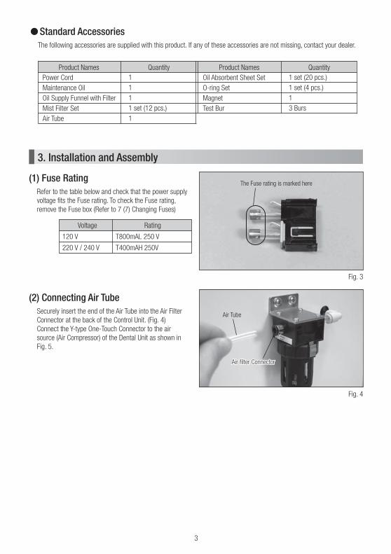
Standard AccessoriesThe following accessories are supplied with this product. If any of these accessories are not missing, contact your dealer.
1
1
1
1 set (12 pcs.)
1
Power Cord
Maintenance Oil
Oil Supply Funnel with Filter
Mist Filter Set
Air Tube
Product Names Quantity
1 set (20 pcs.)
1 set (4 pcs.)
1
3 Burs
Oil Absorbent Sheet Set
O-ring Set
Magnet
Test Bur
Product Names Quantity
(1) Fuse RatingRefer to the table below and check that the power supply
voltage fits the Fuse rating. To check the Fuse rating,
remove the Fuse box (Refer to 7 (7) Changing Fuses)
3. Installation and Assembly
Fig. 3
(2) Connecting Air TubeSecurely insert the end of the Air Tube into the Air Filter
Connector at the back of the Control Unit. (Fig. 4)
Connect the Y-type One-Touch Connector to the air
source (Air Compressor) of the Dental Unit as shown in
Fig. 5.
Fig. 4
Rating
T800mAL 250 V
T400mAH 250V
Voltage
120 V
220 V / 240 V
The Fuse rating is marked here
Air Tube
Air filter ConnectorAir filter ConnectorAir filter Connector
Oil Supply Funnel
with Filter
Maintenance Oil
Oil Drain Bolt
4
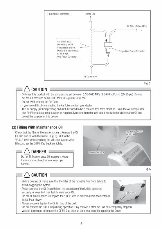
Fig. 5
Air Filter of Care3 Plus
Y-type One-Touch Connector
Air Compressor
Dental UnitExample of connection
Air filter Connector
Cut the air tube
connecting the Air
Compressor and the
Dental Unit and connect
to the Y-type
One-Touch Connector.
CAUTION· Before pouring oil make sure that the filter of the funnel is free from debris to
avoid clogging the system.
· Make sure that the Oil Drain Bolt on the underside of the Unit is tightened
securely. A loose bolt may leak Maintenance Oil.
· Do not fill Maintenance Oil beyond the ‘FULL’ level in order to avoid accidental oil
leaks. Pour slowly.
· Always securely tighten the Oil Fill Cap of the Unit.
· Do not remove the Oil Fill Cap during operation. Only remove it after the Unit has completely stopped.
· Wait for 5 minutes to remove the Oil Fill Cap after an abnormal stop (i.e. opening the Door).
(3) Filling With Maintenance Oil Check that the filter of the funnel is clean. Remove the Oil
Fill Cap and fill with the funnel. (Fig. 6) Fill it to the
"FULL" level, while checking the Oil Level Gauge. After
filling, screw the Oil Fill Cap back on tightly.
Fig. 6
· Only use this product with the air pressure set between 0.35-0.60 MPa (3.5-6.0 kgf/cm2 ) (50-85 psi). Do not
set the air pressure below 0.35 MPa (3.5kgf/cm2 ) (50 psi).
· Do not twist or bend the Air Tube.
· If you have difficulty connecting the Air Tube, contact your dealer.
· The air supply (Air Compressor) and Air Filter need to be clean and free from moisture. Drain the Air Compressor
and Air Filter at least once a week as required. Moisture from the tank could mix with the Maintenance Oil and
defeat the purpose of this device.
CAUTION
Oil Supply Funnel Oil Supply Funnel
with Filterwith Filter
Maintenance OilMaintenance Oil
Oil Drain BoltOil Drain BoltOil Drain Bolt
Do not fill Maintenance Oil in a room where
there is a risk of explosion or near open
flames.
DANGER
Oil Supply Funnel
with Filter
Maintenance Oil
5
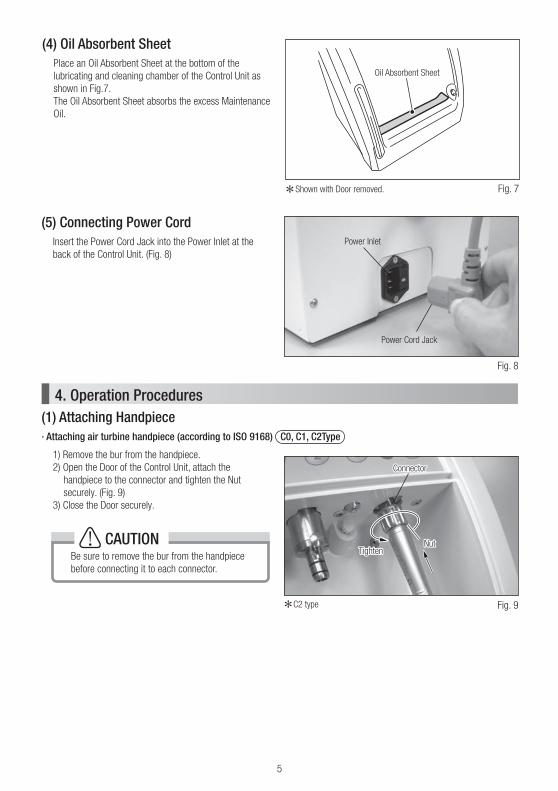
Shown with Door removed.
(4) Oil Absorbent SheetPlace an Oil Absorbent Sheet at the bottom of the
lubricating and cleaning chamber of the Control Unit as
shown in Fig.7.
The Oil Absorbent Sheet absorbs the excess Maintenance
Oil.
Fig. 7
(5) Connecting Power Cord Insert the Power Cord Jack into the Power Inlet at the
back of the Control Unit. (Fig. 8)
Fig. 8
(1) Attaching Handpiece4. Operation Procedures
· Attaching air turbine handpiece (according to ISO 9168) C0, C1, C2Type
1) Remove the bur from the handpiece.
2) Open the Door of the Control Unit, attach the
handpiece to the connector and tighten the Nut
securely. (Fig. 9)
3) Close the Door securely.
Fig. 9C2 type
Be sure to remove the bur from the handpiece
before connecting it to each connector.
CAUTION
Power Inlet
Power Cord Jack
ConnectorConnector
NutNutTightenTighten
Connector
NutTighten
Oil Absorbent Sheet
Test Bur
Straight Handpiece
E-Type Connector
Bur Insertion Hole

6
Connector
NutTighten
· Be sure to remove the bur from the Contra Angle Handpiece before attaching it to Connector. For the Straight
handpiece make sure to insert the supplied Test Bur and lock the chuck before connecting to the Connector.
· For the Contra Angle Handpiece point the Bur Insertion Hole towards the Door and close the Door. Not pointing
the Bur Insertion Hole towards the Door may prevent the Door from closing.
· Attaching E-type handpiece (according to ISO 3964 type) C1, C2, C3Type
Straight Handpiece
1) Insert the supplied Test Bur and lock chuck.(Fig. 10)
2) Open the Door of the Control Unit and attach the handpiece to the E-Type Connector until it locks. (Fig. 11)
3) Close the Door securely.
Contra Angle Handpiece
1) Remove the bur from the Contra Angle Handpiece.
2) Open the Door of the Control Unit and attach the Contra Angle Handpiece to the E-Type Connector Until it locks.(Fig. 11)
3) Point the bur insertion hole toward the Door and close the Door securely. (Fig. 12)
C2 type
C2 type Fig. 12
Fig. 10 Fig. 11
CAUTION
Test BurTest BurTest Bur
Straight HandpieceStraight HandpieceStraight Handpiece
E-Type ConnectorE-Type ConnectorE-Type Connector
Bur Insertion HoleBur Insertion HoleBur Insertion Hole
Door Side
7
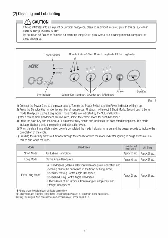
1) Connect the Power Cord to the power supply. Turn on the Power Switch and the Power Indicator will light up.
2) Press the Selector Key number for number of handpieces. First push will select S Short Mode, Second push L:Long
mode Third push E:Extra Long mode. Those modes are indicated by the S, L and E lights.
3) When two or more handpieces are mounted, select the correct mode for each handpiece.
4) Press the Start Key and the Care 3 Plus automatically cleans and Iubricates the connected handpieces. The mode
indicator flashes during the cleaning and lubrication cycle.
5) When the cleaning and lubrication cycle is completed the mode indicator turns on and the buzzer sounds to indicate the
completion of the cycle.
6) Pressing the Air Key blows out air only through the connector with the mode indicator lighting to purge excess oil. Do
this as and when required.
(2) Cleaning and Lubricating
Fig. 13
Above show the total clean-lubricate-purge time.
Lubrication and cleaning in the Extra Long mode may cause oil to remain in the handpiece.
Only use original NSK accessories and consumables. Please consult us.
Mode
Short Mode
Long Mode
Extra Long Mode
Handpiece
Air Turbine Handpiece
Contra Angle Handpiece
· All Handpieces (Make a selection when adequate lubrication and
cleaning cannot be performed in the Short or Long mode.)
· Speed Increasing Contra Angle Handpiece
· Speed Reducing Contra Angle Handpiece
· Other Makes of Air Turbines, Contra Angle Handpieces, and
Straight Handpieces.
Lubrication and cleaning time
Approx. 35 sec.
Approx. 45 sec.
Approx. 50 sec.
Air time
Approx. 60 sec.
Approx. 80 sec.
Approx. 90 sec.
Power Indicator Mode Indicators (S:Short Mode L:Long Mode E:Extra Long Mode)
Start KeyAir Key
Error Indicator Selector Key (1:Left port 2: Center port 3:Right port)
Connector
Loosen
Nut
CAUTION· If blood infiltrates into an Implant or Surgical handpiece, cleaning is difficult in Care3 plus. In this case, clean in
PANA SPRAY plus/PANA SPRAY
· Do not clean Air Scaler or Phatelus Air Motor by using Care3 plus. Care3 plus cleaning method is improper to
those structures.

8
NOTICE
· Removing Air Turbine (according to ISO 9168) C0, C1, C2Type
Open the Door after the mode indicator lights again and
cleaning and lubrication cycle has completely finished.
Loosen the Nut and pull out the handpiece straight from
the Connector. (Fig. 14)
(3) Removing Handpiece
Fig. 14
You can select whether or not to have the buzzer sound at the completion of the cleaning and lubrication cycle.
1) Turn on the Power Switch while pressing the Air Key.
2) In 1 - 2 seconds or less, press the Start Key. The mode indicator changes at that time.
S/L lighting: Buzzer ON
L/E lighting: Buzzer OFF
3) After selecting either mode, press for Air Key 1-2 seconds or press when lit to store the selection in memory.
C2 type
CAUTION· Connect to the correct power supply : AC120V or AC230V
· Use only 3-wire Power Cords that have 3-prong grounding plugs and 3-hole grounded receptacles that accepts
the Control Unit's plug.
· Select an appropriate mode according to the type of handpiece. Select an inappropriate mode may release oil
mist (misty solution) outside the Control Unit.
· When the mode indicator is off, the Care3 Plus is not functioning.
· When the error indicator light is on, make sure the Door is closed securely.
· Immediately after purchase or if you have not used the Care3 Plus for a long time, repeat cleaning and lubrication
approx. four or five times before use.
· Do not open the Oil Fill Cap or Door during operation.
ConnectorConnectorConnector
LoosenLoosenLoosen
NutNutNut
CAUTIONAfter cleaning, when unclean oil has come out of handpiece, clean again.

Detachment Pin
This Pin becomes flat in mounting the Door.
Detachment Pin
Fig. 16
Detachment PinDetachment PinDetachment Pin
Attachment HolePin
9
(1) How to remove the Door1) With pulling the Detachment Pin on the left side of the Door.
2) Remove the Door from the chamber. (Fig. 16)
The Door could be removed when cleaning or replacing the Door gasket.
5. Door
CAUTIONRemove or mount the Door on a flat and stable surface while holding the Control Unit.
LooseTight
Pin for Locking the Door
Pin for Locking the door
· Removing E-type handpiece (according to ISO 3964 type) C1, C2, C3Type
Open the Door after the mode indicator lights again
and cleaning and lubrication cycle has completely
finished. Pull out the handpiece in axial direction while
pressing the Release Button on the E-type Connector.
(Fig. 15)
Fig. 15C2 type
ConnectorConnectorConnector
Release ButtonRelease ButtonRelease Button
CAUTIONWipe off the Maintenance Oil collected at the bottom of the cleaning chamber and the Door. The collected oil could
leak from the bottom of the Door. Dispose of wiped cloth as medical waste according to the laws and regulations
in your country.
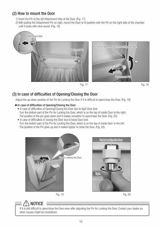
Fig. 18Fig. 17
Detachment PinDetachment PinDetachment Pin
This Pin becomes flat in mounting the Door.This Pin becomes flat in mounting the Door.This Pin becomes flat in mounting the Door.
Detachment PinDetachment PinDetachment Pin
Detachment Pin
Attachment HoleAttachment HoleAttachment HolePinPinPin
1
2
10
(2) How to mount the Door1) Insert the Pin to the left Attachment Hole of the Door. (Fig. 17)
2) With pulling the Detachment Pin on right, mount the Door to fit position with the Pin on the right side of the chamber
until it locks with click sound. (Fig. 18)
Fig. 20Fig. 19
LooseLooseLooseTightTightTight
Pin for Locking the DoorPin for Locking the DoorPin for Locking the Door
Pin for Locking the doorPin for Locking the doorPin for Locking the Door
(3) In case of difficulties of Opening/Closing the DoorAdjust the up-down position of the Pin for Locking the Door if it is difficult to open/close the Door. (Fig. 19)
In case of difficulties of Opening/Closing the Door• In case of difficulties of Opening/Closing the Door due to tight Door lock
Turn the bottom part of the Pin for Locking the Door, which is on the top of inside Door to the right.
The position of the pin goes down and it makes smoother to open/close the Door. (Fig. 20)
• In case of difficulties of closing the Door due to loose Door lock
Turn the bottom part of the Pin for Locking the Door, which is on the top of inside Door to the left.
The position of the Pin goes up and it makes tighter to close the Door. (Fig. 20)
NOTICEIf it is still difficult to open/close the Door even after adjusting the Pin for Locking the Door, Contact your dealer as
other causes might be considered.
Connector
Release Button
11
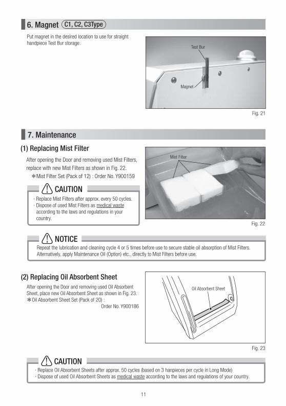
(1) Replacing Mist FilterAfter opening the Door and removing used Mist Filters,
replace with new Mist Filters as shown in Fig. 22.
Mist Filter Set (Pack of 12) : Order No. Y900159
7. Maintenance
Fig. 22
· Replace Mist Filters after approx. every 50 cycles.
· Dispose of used Mist Filters as medical waste
according to the laws and regulations in your
country.
CAUTION
Mist Filter
Repeat the lubrication and cleaning cycle 4 or 5 times before use to secure stable oil absorption of Mist Filters.
Alternatively, apply Maintenance Oil (Option) etc., directly to Mist Filters before use.
NOTICE
CAUTION· Replace Oil Absorbent Sheets after approx. 50 cycles (based on 3 hanpieces per cycle in Long Mode)
· Dispose of used Oil Absorbent Sheets as medical waste according to the laws and regulations of your country.
(2) Replacing Oil Absorbent SheetAfter opening the Door and removing used Oil Absorbent
Sheet, place new Oil Absorbent Sheet as shown in Fig. 23.
Oil Absorbent Sheet Set (Pack of 20) :
Order No. Y900186
Fig. 23
O-ring
Oil Absorbent Sheet
Connector Ring
Put magnet in the desired location to use for straight
handpiece Test Bur storage.
6. Magnet C1, C2, C3Type
Fig. 21
Test Bur
Magnet
12
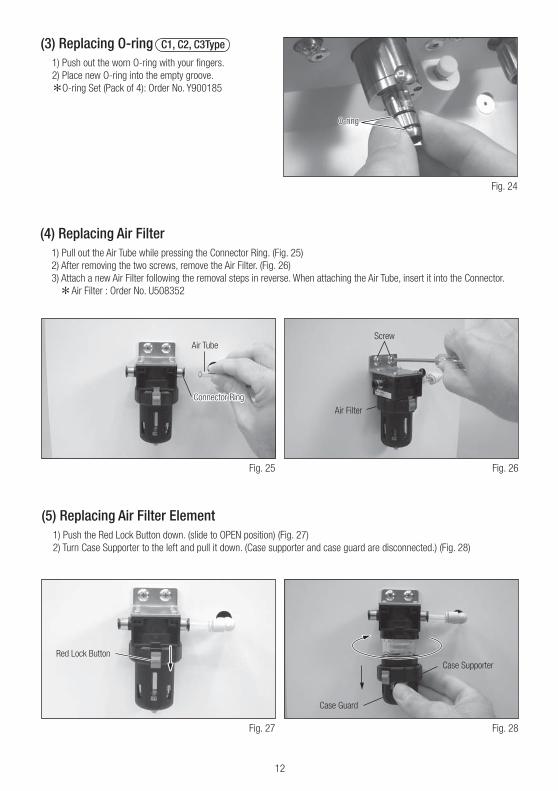
(3) Replacing O-ring C1, C2, C3Type
1) Push out the worn O-ring with your fingers.
2) Place new O-ring into the empty groove.
O-ring Set (Pack of 4): Order No. Y900185
Fig. 24
O-ringO-ringO-ring
Fig. 26Fig. 25
(4) Replacing Air Filter1) Pull out the Air Tube while pressing the Connector Ring. (Fig. 25)
2) After removing the two screws, remove the Air Filter. (Fig. 26)
3) Attach a new Air Filter following the removal steps in reverse. When attaching the Air Tube, insert it into the Connector.
Air Filter : Order No. U508352
(5) Replacing Air Filter Element1) Push the Red Lock Button down. (slide to OPEN position) (Fig. 27)
2) Turn Case Supporter to the left and pull it down. (Case supporter and case guard are disconnected.) (Fig. 28)
Connector RingConnector Ring
Air Tube
Connector Ring
Screw
Air Filter
Fig. 28Fig. 27
Red Lock Button
Case Guard
Case Supporter

13
3) Pull case out. (Fig. 29)
4) Remove the bottom thread of retainer with a screwdriver. (Fig. 30)
5) Remove Retainer & Air Filter Element. (Fig. 31)
6) Install the new Retainer & Air Filter Element, and fix them with the thread. (Screw it up completely)
7) Put Case Guard into Case Supporter, and then put case into Case Guard. (Fig. 32)
8) Attach them to main body by putting Lock Button and groove of main body together. Push case supporter up so that
there is no gap. Turn it right until Lock Button comes to the mark. (Fig. 33)
9) Put lock button up, to lock. (Fig. 34)
Air Filter Element : Order No. U508353
Fig. 32Fig. 31
CAUTION· Do not remove the Air Filter Element until the air supply complety stopped.
· Remove the Air Filter Element, apply the Maintenance Oil to O-ring (for case).
· Replace the Air Filter Element once every one to two years.
· Be careful not to attach the Air Filter upside down.
Fig. 34Fig. 33
Lock Button
mark
Lock Button
Fig. 30Fig. 29
CaseO-ring (for Case)
Screw
Air Filter Element
Retainer
Case
Case Guard
Case Supporter

14
(6) Draining Air FilterWhen water eventually accumulates in the case, press the Drain Button at the lower part of the case to drain the Air Filter.
(Fig. 35)
In addition to the Air Filter, drain the air supply to this device (Air Compressor) at least once a week.
Fig. 35 (7) Changing Fuses
1) Before changing Fuses, be sure to turn off the
Power Switch and unplug the Power Cord.
2) Squeezing the upper and lower ratchets of the
Fuse Box inward at the same time, pull out and
remove the Fuse. (Fig. 36)
3) Replace the Fuse with a new recommended Fuse
(Refer 3. (1) "Fuse Rating") and push it into the
correct position.
Fuse: Order Code (120V) : U433222
Fuse: Order Code (230V) : 1202240000 (T400mAH 250V)
Fig. 36
The air supply (Air Compressor) and Air Filter
need to be clean and free from moisture.
Drain the Air Compressor and Air Filter at least
once a week. Moisture from the tank could
mix in with the Maintenance Oil and defeat the
purpose of this device.
CAUTION
CAUTION
· Before replacing Fuses, ensure that the Power Switch has been turned OFF and the Power Cord has been
unplugged.
· Use a Fuse of Specified rating. (120V: T800mAL 250V, 220V/240V: T400mAH 250V)
Drain Button
Fuse
Fuse Box

15
If a problem occurs, check the following before asking for a repair. If none of these are applicable or the trouble is not
remedied after action has been taken, a failure of this product is suspected. Contact your dealer.
8. Troubleshooting
SolutionPossible Cause and CheckProblem
Insert the Power Cord Plug into the outlet.
Insert the Power Cord Jack into the inlet.
Turn on the Power.
Replace the Fuse with the recommended
Renge.
Press the corresponding selector key to
light mode indicator.
Close the Door securely.
If the Control Unit produces an operating
sound, it has no fault. Check the Air Tube
or the air supply. If the Control Unit
produces no operating sound it has a fault.
Contact your dealer.
Connect the Air Tube to the Connector
Securely.
Set the Air Pressure between
0.35-0.6MPa. (3.5-6kgf/cm² or 50-80psi)
Select the correct mode according to the
type of handpiece.
Connect the handpiece securely.
Select the correct mode according to the
type of handpiece.
When attaching the instruments make
sure that the opening in the head which
receives the bur is facing the Control Unit
Door.
Contact your dealer.
The power does not turn on.
The Control Unit does not clean
and lubricate.
The Control Unit does not
lubricate and clean effectively.
Oil Mist is released outside the
Control Unit.
Error indicator blinks.
Is the Cord Plug inserted into the outlet?
Is the Power Cord Jack inserted into the
inlet of the Control Unit.
Is the power turned ON?
Has the Fuse blown?
Does the mode indicator light up?
IIs the Door open? Is the error indicator
light on?
Remove the Air Tube, press all three
selector keys and press the start button.
Does the Control Unit produce an
operating sound? (Not buzzer)
Is the Air Tube connected securely to the
Air Connector?
Is the air pressure set within the specified
range?
Is the mode set at the Short Mode?
Is the handpiece connected securely?
Has an appropriate mode been selected?
Check that the opening in the instrument
head which receives the bur is facing the
Control Unit Door.
Malfunction of E-Type motor.

16
Check with your dealer for alternative adaptors to mount other manufacturers’ instruments.
KaVo® and MULTIflex® are registered trademarks of Kaltenbach & Voigt GmbH & Co., Germany.
W&H® and Roto Quick® are registered trademarks of W&H Dentalwerk Bürmoos GmbH, Austria.
Bien-Air® and Unifix® are registered trademarks of Bien-Air Dental S.A., Switzerland.
Sirona® is a registered trademark of Sirona Dental Systems GmbH, Germany.
9. Accessories<Spare Parts>
OrderCode
Z016117
Y900138
Y900159
Y900186
U508069
U433090
U508038
U508352
U508353
U508354
U508355
Y900185
U364402
Z070101
U433222
1202240000
Description
Maintenance Oil: 1 bottle (1L)
Maintenance Oil Set (Pack of 6 bottles)
Mist Filter set (Pack of 12)
Oil Absorbent Sheet Set (Pack of 20)
Door
Oil Supply Funnel with Filter
Air Tube
Air Filter
Air Filter Element
Case
O-ring (for case)
O-ring set (Pack of 4)
Magnet
Test Bur
Fuse (for 120V)
Fuse (for 230V)
<Instrument Adaptors>
Product No.
Z280035
Z257010
T904
Z257020
Z257021
Z280022
Z257023
Z280042
Model
E-Type Adaptor
PTL Adaptor
B2/M4 Adaptor
KV Adaptor (For KaVo® MULTIflex® Coupling)
WH Adaptor (For W&H® Roto Quick® Coupling)
BA Adaptor (For Bien-Air® Unifix® Coupling)
SR Adaptor (For Sirona® Quick Coupling)
F-type Adaptor
The Manufacturer warrants its products to the original purchaser against defects in material and workmanship subject to
correct installation, use and servicing. Maintenance Oil, Mist Filter, Oil Absorbent sheet, and O-ring etc. are consumable
components, and are not covered by this warranty.
10. Warranty

17
SPECIFICATIONS
Model
Rated Voltage
Input Voltage
Air Pressure
Reservoir Capacity
Dimensions
Weight
NE187
AC120V 10% 60Hz
AC230V 10% 50/60Hz
120V:19.0VA
230V:19.5VA
0.35-0.6MPa (3.5-6.0kgf/cm2) (50-85psi)
350mL
W280 x D275 x H 360 mm
C0 Type:6.8kg C1 Type:7.1kg
C2 Type:7.2kg C3 Type:7.3kg

M2013.08.20 003