Embed Size (px)
Citation preview
ISRAEL ELECTRIC CORPORATION
INFORMATION SYSTEMS & COMMUNICATIONS DIVISION
COMMUNICATION AND ELECTRONICS UNIT
COMMUNICATION DESIGN DEPARTMENT
SPECIFICATION
for
UTILITY MULTIPLEXER
FOR TELEPROTECTION
12-2013
Version 1.00
Written by: M. Koritny, E. Gabzo.
Checked by: Y. Klein, R. Stern
Approved by: A. Cohen, A. Akrish
July 2013
UTILITY MULTIPLEXER FOR TELEPROTECTION ANNEXURE B1
SPEC 12-2013 VERSION 1.00
Page 2 of 17
UTILITY MULTIPLEXER FOR TELEPROTECTION
SPECIFICATION 12-2013
1. (I) General
The Purchaser, the Israel Electric Corporation, intends to purchase and install at its facilities telecommunication system (hereinafter: "the System") to be interfaced with the teleprotection equipment for high-voltage lines (HVL). The System shall comprise the Multiplexers for Teleprotection (MTP) and corresponding Management System. The terms Multiplexer(s), MTP, "Equipment" or "equipment" are interchangeable and shall mean said Utility Multiplexer for Teleprotection.
This document establishes the structure of the specification for MTP to be submitted as part of the Offeror proposal in reply to Purchaser's Request for Proposal. In addition, this document specifies Purchaser's requirements with which the equipment must comply.
2. N.A.
3. (I) Applicable Documents
3.1 The Offeror shall list here all documents which form a part of his specification to the extent specified therein.
3.2 The following last edition documents shall be adhered to where applicable unless stated otherwise below in this Specification:
ITU-T Standards, Recommendations and Publications, last edition,
IEC and IEC CISPR Standards, Recommendations and Publications,
IEEE Standards, Recommendations and Publications,
RFC Recommendations,
ETSI European Standards, Recommendations and Publications,
ANSI and EIA American Standards, Recommendations and Publications,
National Standards, Recommendations and Publications.
UTILITY MULTIPLEXER FOR TELEPROTECTION ANNEXURE B1
SPEC 12-2013 VERSION 1.00
Page 3 of 17
Recognized Public Standards (for an example RFC, IETF, etc.).
3.3 The references to National and Public standards and recommendations shall be accompanied with quantitative physical terms and references to equivalent international standards and recommendations.
3.4 The proposed System shall not be limited by stated hereinafter minimal requirements and preferences.
3.5 In case the proposed equipment conforms to recommendations, standards and/or specifications other than those specified in Annexure B1, the Offeror shall define these recommendations, standards and/or specifications and shall attach compliance (comparison) tables for each such case. Non compliance points shall be highlighted. Copies of each such recommendation, standard and/or specification shall be submitted as it applicable to this Specification.
4. (I) Requirements
This section contains the performance requirements and physical characteristics of the equipment. The Offeror will describe in detail his proposed solution to Purchaser’s requirements. Unless purely descriptive by nature, the Offeror’s solution will be stated in quantitative physical terms with tolerances which can be verified by analytical test, demonstrative data or inspection of the equipment and related supporting engineering data.
4.1 System Definition
4.1.1 Functional description
The MTR shall provide communication channels for teleprotection signals, utilizing multiplexing, drop and insert technique. The Multiplexers shall have modular design and provide support for equipment redundancy of the main critical modules.
The complete configuration that ensures the minimum losses of signal transmission in case of a break down in the equipment or its interfaces is required.
The System shall provide protection path ability in case of failure or loss the communication channel between adjacent multiplexers.
4.1.2 System configuration
In this paragraph the Offeror must propose complete configurations of the System in accordance with the contents of this Specification. The Offeror shall submit a detailed description of the System, its architecture and functions and shall explain how it fulfills the Purchaser's requirements.
4.1.3 Line Interfaces
4.1.3.1. Multiplexers shall be connected to communication network via Line Interface(s) (LI) and provide local site services via Communication Interface(s) (CI). Termination, drop and insert scheme shall be applicable
UTILITY MULTIPLEXER FOR TELEPROTECTION ANNEXURE B1
SPEC 12-2013 VERSION 1.00
Page 4 of 17
both for any single interface as well as for any combination (group) of the same type interfaces.
4.1.3.2. All LI and CI shall incorporate protection against surge, spikes, overvoltage and short circuit.
4.1.3.3. Test circuits for any type LI/CI shall be an integral part of the proposed equipment. Minimal self-testing facilities that shall be provided and explained in detail are interface monitoring, local and remote loopbacks.
4.1.3.4. (M) LIs shall be E1 electrical interfaces accordingly with ITU-T Standards G.703, G.706, G.704, G.732N and G.732S. The line impedance shall be resistive 120 Ohm, balanced.
4.1.3.5. The preferred termination for LI is RJ-45 connector.
4.1.3.6. (L) The network topologies for LI connections shall be point-to-point (PTP), line (chain) and ring (closed chain), at least.
4.1.3.7. (S) The fast path failover restoration of line interfaces shall be provided. The Purchaser's preference for this datum is equal or less than 20 ms.
4.1.3.8. At least one LI shall be allocated per single module. The chassis or rack facility shall provide the slots for 2 LI modules, at least, in typical MTR configuration.
4.1.4 (S) Communication Interfaces for distance protection (DP)
4.1.4.1. (M) CI for distance protection shall be per IEC 60834-1.
The CI shall support any protection scheme as per IEC 60834-1:
- permissive tripping schemes, - intertripping schemes (direct or transfer tripping), - blocking protection schemes.
4.1.4.2. The overall transmission time shall not exceed 10 ms for any permissive,
blocking s and intertripping scheme. 4.1.4.3. The probability of receiving an unwanted command shall not exceed 10
-8 at
the worst Bit Error Rate (BER). The probability of missing command at BER 10
-6 shall not exceed 10
-4 for any scheme.
4.1.4.4. The bidirectional commands shall be independent and grouped in 4 signals per single group. There shall be one group at least per single DP module. The chassis or rack facility shall provide slots for 2 DP modules, at least, in typical MTR configuration.
4.1.4.5. The input/output physical termination shall be electrically isolated and operate
at 176 to 264 Vdc range. The nominal voltage shall be 220Vdc.
4.1.4.6. The outputs shall be normally open relay contacts and be rated as follows: - nominal voltage: 250 V AC or DC, - make: 3A and carry for 0.2s, inductive load (L/R equal or less than 0.04s),
UTILITY MULTIPLEXER FOR TELEPROTECTION ANNEXURE B1
SPEC 12-2013 VERSION 1.00
Page 5 of 17
- carry: 1A continuous, - break: DC 30W resistive, 15W inductive load (L/R equal or less than 0.04s), - minimal contact load: 20mA at 24V AC/DC, - loaded contact durability: for signal contact - equal or greater than 10,000 operations; tripping contact - equal or greater than 1,000 operations, - unload contact durability: equal or greater than 100,000 operations.
The termination shall be suitable for connection of 2.5 mm2 wires.
4.1.4.7. The logical inputs shall operate at minimal switching current 3 mA.
4.1.4.8. (I) The MTR shall provide programmable settings for unblock timer, contact bounce override, trip of command output hold time, security delay for permissive and intertripping protection schemes (meant delay in operation), etc. The Offeror shall describe those features in detail. The Purchaser reserves the right to request and receive specific settings fitted to his own HVL environment.
4.1.4.9. (I) The interface shall provide signaling for blocking DP command flow when no communication with the corresponding remote interface occurs. Blocking shall be provided simultaneously at both sides of the affected link for any abnormal condition including total power fail of the MTP.
4.1.5 Communication Interfaces for differential protection (DIP)
4.1.5.1. (M) CI for differential protection shall be per IEEE C37.94.
4.1.5.2. (S) There shall be one or more CI interfaces per single DIP module. The chassis or rack facility shall provide the slots for 2 DIP modules, at least, in typical MTR configuration.
4.1.6 (G) Local Interface for Craft Terminal and Interface for Management
System
The interface for local craft terminal or computer shall be Ethernet 100Base-T, RJ-45. The same interface shall be suitable for connection of remote craft terminal or Management System. It is preferred that there shall be separate interfaces for local and remote without interrelation reciprocal collisions.
4.1.7 (S) Power Supply Interface
4.1.7.1. (S) The voltage range for power supply shall be 176 to 264 Vdc, floating (i.e. no connection to ground of positive or negative pole). The nominal voltage shall be 220Vdc. The multiplexer shall withstand to , at least, 5% AC ripple on the DC power supply.
4.1.7.2. (G) The power supply module(s) shall be tolerant to reverse polarity supply and power supply voltage disturbance caused by dips, interruptions and voltage skips on grounding – no unwanted commands shall be generated. The Offeror shall describe in detail the utilized preventing methods. Such disturbances withstand shall be in accordance with requirements of Attachment 2.
UTILITY MULTIPLEXER FOR TELEPROTECTION ANNEXURE B1
SPEC 12-2013 VERSION 1.00
Page 6 of 17
4.1.7.3. (M) The MTR shall have redundant power supply by means of independent modules.
4.1.7.4. The Offeror shall define power consumption for each module. Heat dissipation (in BTU/h and Watts) shall be provided for typical MTP configurations.
4.1.8 (G) Functional description
The MTR shall provide capabilities for further expansion. The expansion shall include hardware, firmware and software updates and upgrades.
The MTR hardware expansion shall be performed by addition and/or replacement modules, and by addition of an expansion chassis (if any).
Software and firmware update/upgrade shall be provided by the local and remote downloads, in-service, and shall not affect traffic in any way.
4.1.9 (G) Items to be supplied
4.1.9.1. The typical configuration of the single MTP shall be two LIs, two CIs for distance protection and two CIs for differential protection, non-redundant common logic/maintenance and redundant power supply modules. The chassis shall have spare slots for expansion.
4.1.9.2. The Offeror must define and include in his proposal all the chassis, modules, connectors, terminal blocks, adapters, cables, patch panels, power boxes, blanking plates, special tools, other hardware and materials required for installation, operation and maintenance of the multiplexers.
4.1.9.3. The Offeror shall define and include in his proposal as a Purchaser's option all the chassis, modules, cables and other hardware and software that exceed the minimal requirements of this Specification.
4.1.10 (S) Compatibility To be considered as an advantage the compatibility of MTRs with Purchasers MTRs FOCUS type manufactured by the AMTETEK (USA).
4.2 (S) Physical Characteristics, Design and Construction
4.2.1 (M) The equipment shall be 19" rack mountable. Chassis along with its wiring in any configuration shall be affordable for installation into standard 19" cabinet with the following dimension: height equal 2000 or/and 2200 mm, width equal 600 mm and depth equal 600 mm.
4.2.2 (G) The Offeror shall provide the drawings for typical installation of a single and multiple multiplexers in the cabinet. The additional requirements for cabinet, such as ventilation, power supply components (circuit breakers, necessity of RFI filters, if any, etc.) shall be specified.
4.2.3 The Offeror shall state all physical characteristics pertaining to his proposed equipment. The following data shall be specified for each chassis/subassembly/ /module of the proposed equipment.
Weight.
UTILITY MULTIPLEXER FOR TELEPROTECTION ANNEXURE B1
SPEC 12-2013 VERSION 1.00
Page 7 of 17
Dimensions (D x W x H) (including accessibility requirements for operation, maintenance and installation).
Durability factors to indicate degree of raggedness.
Health and safety criteria, if any. Indicate standards, specifications and precautions to preclude hazard to personnel, equipment or both.
Vulnerability factors including fire, electromagnetic radiation, impact etc.
4.2.4 (G) Interchangeability
The Offeror shall state here interchangeability of every module/part/ /component having an identical part number.
4.2.5 (I) Mechanical Robustness
Vibration test, shock response and seismic qualification level shall be in accordance with requirements of Attachment 2.
4.2.6 (I) Nameplates and Marking
All data in the nameplates and marking shall be in English or Hebrew.
4.3 (I) Reliability
4.3.1 The Offeror shall specify the System Life Expectancy (LE) and Mean Time Between Failures (MTBF), calculated and demonstrated (DMTBF). The methods of calculation shall be MIL-HDBK-217F (preferred by Purchaser) or Telcordia SR332. The MTBF data shall be specified along with the confidence level 90% for the MTR and each its module when operated within their specified environmental extremes and failure rate during the service life from the second year and thereafter.
4.3.2 (L) The minimal LE shall be no less than 15 years. The calculated MTBF for the MTR in typical configuration (as defined above in paragraph 4.1.9.1) shall be no less than 200,000 hours.
4.3.3 (G) The Offeror shall indicate the methods by which the MTBF values were determined and shall submit detailed calculation and supporting data. The Offeror shall specify those units where redundancy is recommended.
4.4 (S) Maintainability
The Offeror shall specify maintainability values (including confidence levels where appropriate) and provisions of each subassembly/module and of the equipment in accordance with the following topics as a minimum:
4.4.1 Mean times :
between failures (MTBF), to repair (MTTR), between consecutive preventive/periodic maintenance activities (if any).
4.4.2 Maintenance complexity as per number of the personnel and their skill levels,
variety of test and support equipment.
4.4.3 Testability. It shall be detailed for:
UTILITY MULTIPLEXER FOR TELEPROTECTION ANNEXURE B1
SPEC 12-2013 VERSION 1.00
Page 8 of 17
field fault detection, built in test description (loopbacks, alarms, etc.), list of test points.
4.4.4 (I) Adjustments, alignments and calibrations. No adjustment and no alignment shall be required when replacing subassemblies and modules during field maintenance and repair activities.
4.4.5 (I) All field maintenance and troubleshooting activities, especially module replacement, shall be performed while the equipment is in operation without or minimal interfering with its proper functioning and without causing any damage whatsoever.
The Offeror shall specify list activities that lead to traffic interrupt or perturbation in adjacent modules.
4.5 (S) Environmental Conditions
The Offeror shall make reference to the fact that the Multiplexers shall be installed in the vicinity of 400 kV or 161 kV lines and therefore shall be susceptible to induction and to line switching effects.
The Offeror shall state the environmental conditions which are met by his proposed equipment. The Offeror must state those cases in which the proposed equipment performance is degraded due to certain simultaneous values of two (or more) environmental parameters.
4.5.1 High Voltage Withstand and Electromagnetic Environment
The MTR withstand shall be in accordance with Attachment 2.
4.5.2 The Ambient Environment
The minimal Purchaser's requirement for operation, storage and transportation shall be in accordance with Attachment 2.
The MTR shall withstand the single leaps of maximal ambient temperature above +55°C for 96 hours cumulative.
4.5.3 Safety shall be in accordance with EN 60950-1.
4.6 (G) System Security, Management and Alarm Systems
4.6.1 The Offeror shall propose management facility that includes hardware and layered software.
4.6.2 (L) The management capabilities for the System shall be provided for:
topology management
configuration tools
fault management
performance monitoring
alarm management
security management
Management System back-up and redundancy facilities
UTILITY MULTIPLEXER FOR TELEPROTECTION ANNEXURE B1
SPEC 12-2013 VERSION 1.00
Page 9 of 17
4.6.3 (M) The management shall be possible either locally or remote, either in-band or outband. The management impact that applied to specific multiplexer(s) shall not affect the routine operation of adjacent multiplexers in any way. Loss of communication with Management System shall not affect the traffic.
4.6.4 The Network Manager and Element Manager shall be proposed. The Offeror shall define all software, firmware, licenses and hardware required for these Managers. All the tools to be proposed by Offeror shall be "state of the art" and last version available on the market shall be supplied.
4.6.5 The Craft Terminal for field commissioning shall be provided. At least Element Manager shall be installed at the Craft Terminal along with additional tools for diagnostic (if any) and set of reference documentation for installation /commissioning /troubleshooting.
4.6.6 The hardware for Network and Element Manager shall be Wintel Personal Computer (PC). Preferred hardware for Craft Terminal shall be PC notebook or ultrabook. The security management software and/or hardware components shall be provided for authorised only access.
4.6.7 The Offeror shall propose Graphic User Interface (GUI) module with SNMP (Simple Network Management Protocol), version 3, agent based software and relevant Management Information Base (MIB) libraries.
4.6.8 The additional services - HTTP/HTTPS built-in server as additional component for element managing, PPP, FTP/TFTP, SMTP, SSH, and, especially, cellular Short Message Service (SMS) protocol should be considered as an advantage.
4.6.9 (M) The System and its components shall comply with security requirements as per Attachment 3.
4.6.10 In addition, the equipment shall provide an alarm system that includes dry contact array for critical, major, minor and warning alarms, at least, local displays, audible and visible alarm, etc.
4.7 (G) Documentation
The Offeror shall include in his proposal all the required documents that are mentioned in this tender. The documentation to be supplied shall conform in coverage and in detail to the levels of maintenance, training, installation and testing that are defined in the Specification and in the SOW as well. The Offeror shall define the documentation in detail. The documentation shall be a part of the Offeror's proposal. The documentation shall not be limited by the list of one that is mentioned in the paragraphs 4.7.
Purchaser's General Requirements
(a) All data and descriptive material in the above drawings and documents shall be in English or/and in Hebrew.
(b) All dimensions and quantities throughout the above drawings and documents shall be in the M.K.S (Meter, Kilogram, Second) measurement units.

UTILITY MULTIPLEXER FOR TELEPROTECTION ANNEXURE B1
SPEC 12-2013 VERSION 1.00
Page 10 of 17
(c) All the drawings and documents shall conform to the requirements of the Statement of Work (SOW) and the Specification.
(d) All documentation shall be the Work supplied up-to-date version.
(e) All documentation shall be clear, legible, of suitable quality for storage for the life of the equipment.
4.7.1 Mechanical/Assembly Drawings
4.7.2 Technical documents and reports a) type test reports. b) RMA reports. c) EMC reports.
4.7.3 Reference list for field experience of offered Equipment and
Confirmation of at least 3 years of operational field experience
4.7.4 Acceptance Test Procedures
4.7.5 Manuals a) Maintenance manuals for field maintenance level.
b) Test equipment manuals, including testing instructions and test equipment description, theory of operation and electronic schematics.
c) Storage instructions. d) Installation Manual. e) Operational Manuals for the equipment and Management System, f) Training manual.
4.7.6 Valid Certificate of compliance of the ISO 9001:2008 of Manufacturer,
issued by authorized institution.
4.8 (G) Maintenance
The Offeror shall specify the equipments maintenance principles in accordance with the following topics:
4.8.1 Test equipment
The Offeror shall specify all test equipment for and accessories for technicians and for system engineer required to perform the following activities:
a) preventive/periodic maintenance, b) installation, c) field troubleshooting, d) laboratory level repairs, down to the level of electronic component
replacement on electronic cards (if applicable). The test equipment shall be specified according to the following categories:
a) special test equipment, b) special fixtures, accessories and software,
UTILITY MULTIPLEXER FOR TELEPROTECTION ANNEXURE B1
SPEC 12-2013 VERSION 1.00
Page 11 of 17
c) standard test equipment and accessories.
4.8.2 Adjustments, alignments and calibrations
Define all adjustments, alignments and calibrations which are required for the proper operation of the equipment without any performance degradation. The following shall be specified:
(a) definition of adjustment/alignment/calibration/tuning activity, (b) recommended time interval for performing this activity, (c) recommended maintenance level for performing same.
4.8.3 Preventive/periodic maintenance
The Offeror shall specify policy and attach comprehensive procedures for periodic maintenance, required to maintain the proposed equipment in operational non-degraded state and prevent it from developing long term damages.
4.8.4 Troubleshooting
The Offeror shall state policy and attach comprehensive procedures for field troubleshooting detailing, in step by step description, fault detection and localization using built-in, standard and special test equipment; fault repair and System operability verification tests.
4.8.5 Laboratory level repairs
The Offeror shall state policy and attach comprehensive procedures for laboratory level repair policy, including component replacement (if applicable).
4.8.6 Maintenance times
The Offeror shall specify mean times required to perform the three types of maintenance mentioned in 3.8.3, 3.8.4 and 3.8.5 above.
4.8.7 Accessibility
The Offeror shall specify accessibility requirements for performing the necessary maintenance and troubleshooting activities. Special attention shall be directed to items installed in locations having limited accessibility.
4.8.8 Follow-on support (additional details see in SOW, section 13)
The Supplier shall specify the issues peculiar to the equipment which shall be candidates for updates, improvements or replacement, during the life cycle of the equipment.
4.8.9 Provisioning
The Supplier shall specify policy and procedures for provisioning, required for proper operation and maintenance of the equipment. Attention shall be directed, among other things to modules, subassemblies, components, mechanical parts, cables, wires, and consumables. Recommended spare parts list formulation method shall be detailed, the guidelines for which shall be as follows:
UTILITY MULTIPLEXER FOR TELEPROTECTION ANNEXURE B1
SPEC 12-2013 VERSION 1.00
Page 12 of 17
a) three year provisioning period b) field level and/or laboratory level maintenance c) quantities based on RMA specified values (such as MTBF, MTTR, and
repair turn around time).
4.8.10 Infrastructure
The Offeror shall specify, in quantitative terms, the infrastructure required for operation and maintenance of the equipment.
5. (G) Preparation for Shipping and Storage Instructions
5.1 The Supplier shall specify the following regarding the equipment:
a) preservation and packaging, b) packing, c) prolonged storage instructions, d) instructions for repackaging by Purchaser.
5.2 Purchaser’s requirements for packing
5.2.1 The Supplier shall provide with every shipment of Equipment list of all deliverables including the part numbers and serial numbers of each item, card or sub module
5.2.2 Each and every item that shall be delivered must have at least the following marking data:
(a) Order No, (b) Supplier’s name, (c) equipment identification (type and catalog No.), (d) Purchaser’s name, (e) Purchaser’s catalog No.
5.2.3 Labeling method of the packages shall be according to Purchaser's requirements attached to Order to enable easy identification in Purchaser's stores.
5.2.4 Marking shall be provided for each side and for top of the group packing. Individual packing for modules shall be provided for equipment identification and Purchaser’s catalog No. marking with enlarged font, 2 cm height at least.
UTILITY MULTIPLEXER FOR TELEPROTECTION ANNEXURE B1
SPEC 12-2013 VERSION 1.00
Page 13 of 17
ATTACHMENT 1
“OFF THE SHELF" PRODUCT: REQUIREMENTS
The Equipment shall be an "off the shelf" product, complying with the requirements defined below.
The Equipment:
Is completely defined (design, construction and performance) by a formal technical specification.
Is manufactured in accordance with formal production drawings, processes and procedures which govern all stages and aspects of the manufacturing process.
Have successfully passed all qualification tests and the environmental tests in particular.
Is manufactured with strict adherence to the prescribed quality assurance procedures, which have to include in-process inspection procedures.
Is currently manufactured and is being used in large quantities and the accumulated operational data proves high reliability indicating the System(s) is mature.
Is regularly checked for reliability by field data collection, collation and corrective action taken when needed.
Is accompanied by a complete set of manufacturing drawings and procedures, reliability prediction, user manuals and maintenance manuals.
UTILITY MULTIPLEXER FOR TELEPROTECTION ANNEXURE B1
SPEC 12-2013 VERSION 1.00
Page 14 of 17
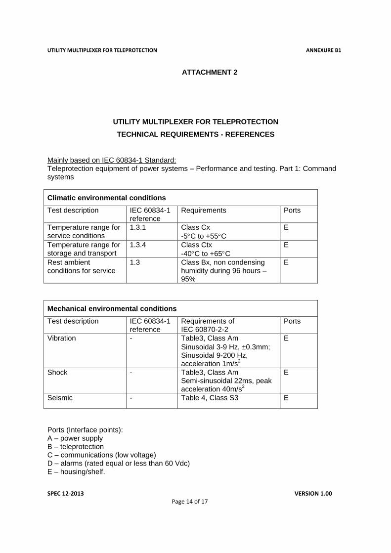
ATTACHMENT 2
UTILITY MULTIPLEXER FOR TELEPROTECTION
TECHNICAL REQUIREMENTS - REFERENCES
Mainly based on IEC 60834-1 Standard: Teleprotection equipment of power systems – Performance and testing. Part 1: Command systems
Climatic environmental conditions
Test description IEC 60834-1 reference
Requirements Ports
Temperature range for service conditions
1.3.1 Class Cx
-5C to +55C
E
Temperature range for storage and transport
1.3.4 Class Ctx
-40C to +65C
E
Rest ambient conditions for service
1.3 Class Bx, non condensing humidity during 96 hours – 95%
E
Mechanical environmental conditions
Test description IEC 60834-1 reference
Requirements of IEC 60870-2-2
Ports
Vibration - Table3, Class Am
Sinusoidal 3-9 Hz, 0.3mm; Sinusoidal 9-200 Hz, acceleration 1m/s
2
E
Shock - Table3, Class Am Semi-sinusoidal 22ms, peak acceleration 40m/s
2
E
Seismic - Table 4, Class S3 E
Ports (Interface points): A – power supply B – teleprotection C – communications (low voltage) D – alarms (rated equal or less than 60 Vdc) E – housing/shelf.
UTILITY MULTIPLEXER FOR TELEPROTECTION ANNEXURE B1
SPEC 12-2013 VERSION 1.00
Page 15 of 17
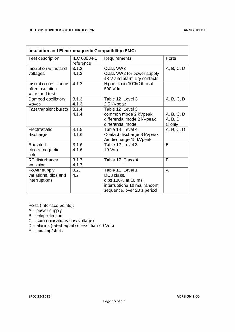
Insulation and Electromagnetic Compatibility (EMC)
Test description IEC 60834-1 reference
Requirements Ports
Insulation withstand voltages
3.1.2, 4.1.2
Class VW3 Class VW2 for power supply 48 V and alarm dry contacts
A, B, C, D
Insulation resistance after insulation withstand test
4.1.2 Higher than 100MOhm at 500 Vdc
Damped oscillatory waves
3.1.3, 4.1.3
Table 12, Level 3, 2.5 kVpeak
A. B, C, D
Fast transient bursts 3.1.4, 4.1.4
Table 12, Level 3, common mode 2 kVpeak differential mode 2 kVpeak differential mode
A, B, C, D A, B, D C only
Electrostatic discharge
3.1.5, 4.1.6
Table 13, Level 4, Contact discharge 8 kVpeak Air discharge 15 kVpeak
A. B, C, D
Radiated electromagnetic field
3.1.6, 4.1.6
Table 12, Level 3 10 V/m
E
RF disturbance emission
3.1.7 4.1.7
Table 17, Class A E
Power supply variations, dips and interruptions
3.2, 4.2
Table 11, Level 1 DC3 class, dips 100% at 10 ms; interruptions 10 ms, random sequence, over 20 s period
A
Ports (Interface points): A – power supply B – teleprotection C – communications (low voltage) D – alarms (rated equal or less than 60 Vdc) E – housing/shelf.
UTILITY MULTIPLEXER FOR TELEPROTECTION ANNEXURE B1
SPEC 12-2013 VERSION 1.00
Page 16 of 17
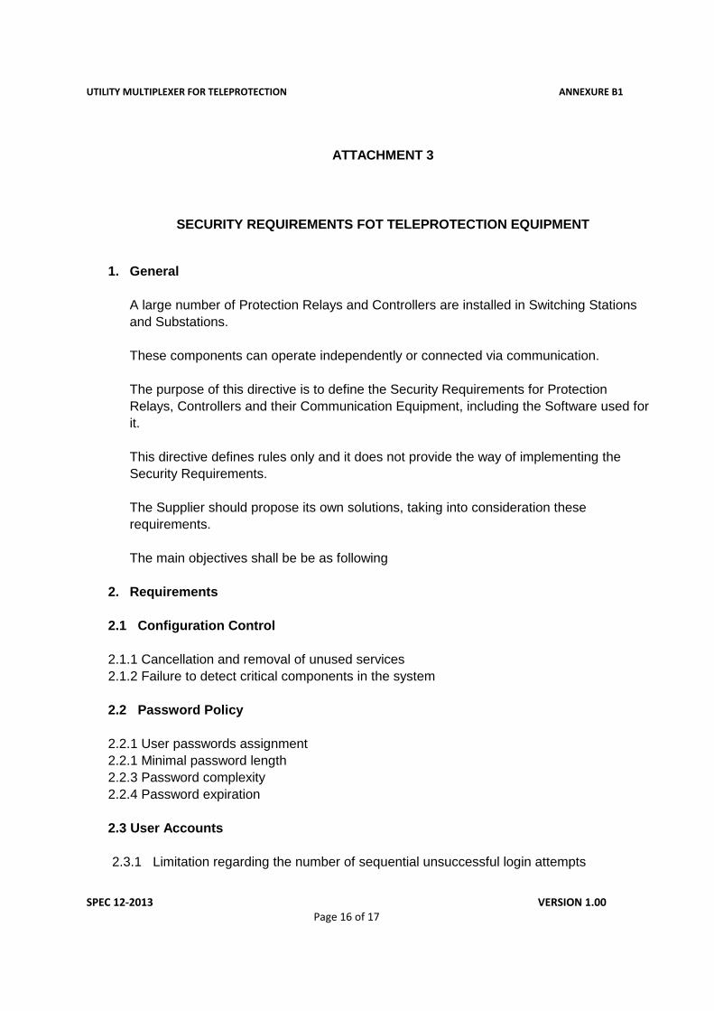
ATTACHMENT 3
SECURITY REQUIREMENTS FOT TELEPROTECTION EQUIPMENT
1. General
A large number of Protection Relays and Controllers are installed in Switching Stations
and Substations.
These components can operate independently or connected via communication.
The purpose of this directive is to define the Security Requirements for Protection
Relays, Controllers and their Communication Equipment, including the Software used for
it.
This directive defines rules only and it does not provide the way of implementing the
Security Requirements.
The Supplier should propose its own solutions, taking into consideration these
requirements.
The main objectives shall be be as following
2. Requirements
2.1 Configuration Control
2.1.1 Cancellation and removal of unused services
2.1.2 Failure to detect critical components in the system
2.2 Password Policy
2.2.1 User passwords assignment
2.2.1 Minimal password length
2.2.3 Password complexity
2.2.4 Password expiration
2.3 User Accounts
2.3.1 Limitation regarding the number of sequential unsuccessful login attempts
UTILITY MULTIPLEXER FOR TELEPROTECTION ANNEXURE B1
SPEC 12-2013 VERSION 1.00
Page 17 of 17
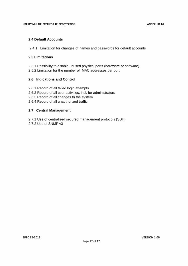
2.4 Default Accounts
2.4.1 Limitation for changes of names and passwords for default accounts
2.5 Limitations
2.5.1 Possibility to disable unused physical ports (hardware or software)
2.5.2 Limitation for the number of MAC addresses per port
2.6 Indications and Control
2.6.1 Record of all failed login attempts
2.6.2 Record of all user activities, incl. for administrators
2.6.3 Record of all changes to the system
2.6.4 Record of all unauthorized traffic
2.7 Central Management
2.7.1 Use of centralized secured management protocols (SSH)
2.7.2 Use of SNMP v3