Embed Size (px)
Citation preview
E Series™ Broadband Services Routers
E120 and E320 Module Guide
Release
13.3.x
Published: 2012-09-11
Copyright © 2012, Juniper Networks, Inc.

This guide provides an overview and description of the line modules (LMs), switch route
processor (SRP)modules, switch fabric modules (SFMs), and input/output adapters
(IOAs) available for the Juniper Networks E120 and E320 Broadband Services Routers.
NOTE: A releasemay support multiple versions of amodule or IOA. Forinformation, seeSoftwareCompatibility in JunosESystemBasicsConfigurationGuide, Chapter 6, Managing Modules.
Table 1 on page 3 lists the modules and IOAs supported by the router.
This guide also contains the following appendixes:
• IOA Protocol Support on page 49
• Module and Slot Combinations on page 73
• Module Name Cross-Reference Information on page 77
• Product Reclamation and Recycling Program on page 79
For more information about E120 routers, E320 routers, modules, and IOAs, refer to the
following guides:
• Modules that have reached end-of-life—E Series End-of-Life Module Guide
• Module installation andmaintenance—E120 and E320 Hardware Guide
• Managing routers—JunosE System Basics Configuration Guide
• Configuring modules—JunosE Link Layer Configuration Guide
Copyright © 2012, Juniper Networks, Inc.2
E120 and E320 13.3.x Module Guide

Table 1: Modules and IOAs
PageFirst JunosE SupportModule LabelModule/IOA Type
LineModule
57.0.1ES24GLM
LM-4
77.2.0ES210GUPLINKLM
LM-10 Uplink
98.0.0ES210G LM
LM-10
1110.1.0ES210G ADV LM
LM-10 ADV
SRPModule
127.0.1SRP-100SRP-100
148.2.0SRP-120SRP-120
167.3.0SRP-320SRP-320
SFMModule
187.0.1SFM-100SFM-100
198.2.0SFM-120SFM-120
207.3.0SFM-320SFM-320
Gigabit Ethernet IOA
217.0.1ES2-S1GE-4IOA
GE-4 IOA
257.2.0ES2-S1GE-8IOA
GE-8 IOA
299.0.0ES2-S3GE-20IOA
GE-20 IOA
337.2.0ES2-S210GE PRIOA
10GE PR IOA
OC3/STM1 ATM IOA
3Copyright © 2012, Juniper Networks, Inc.
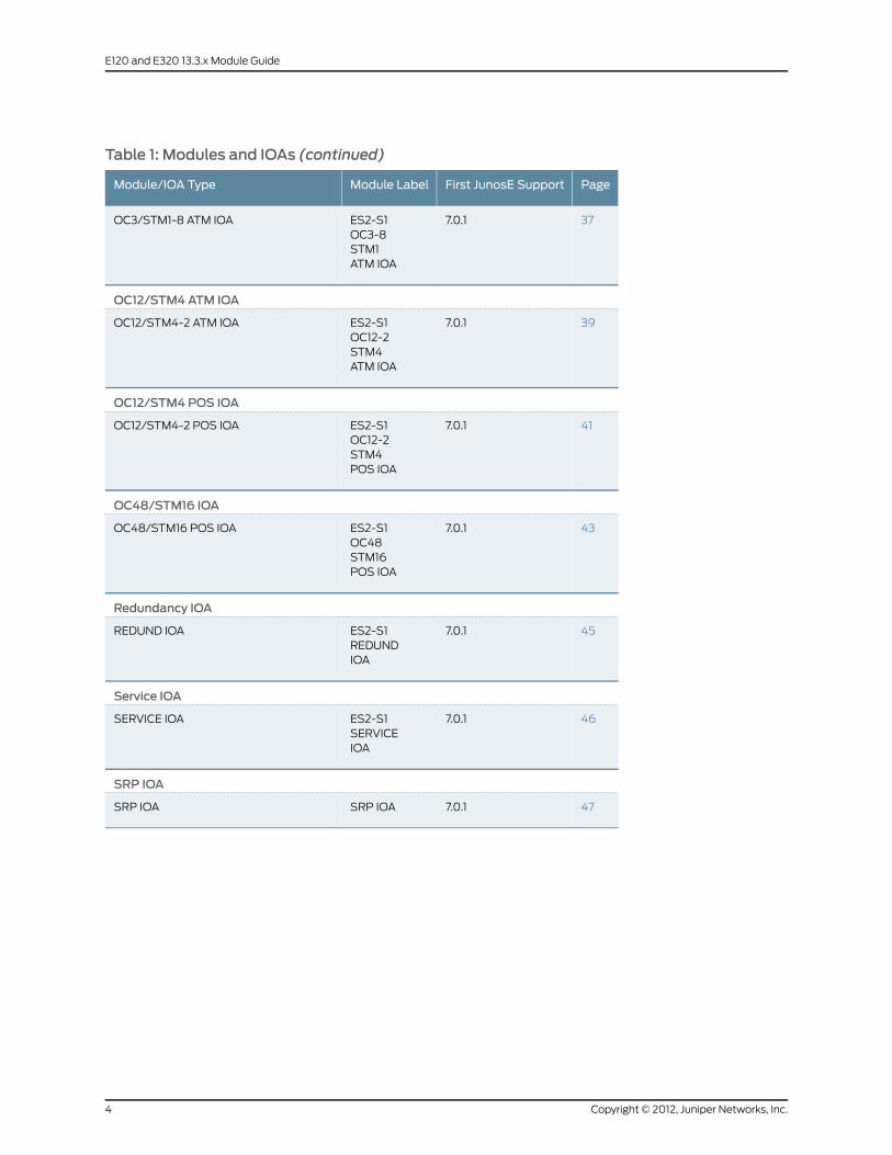
Table 1: Modules and IOAs (continued)
PageFirst JunosE SupportModule LabelModule/IOA Type
377.0.1ES2-S1OC3-8STM1ATM IOA
OC3/STM1-8 ATM IOA
OC12/STM4ATM IOA
397.0.1ES2-S1OC12-2STM4ATM IOA
OC12/STM4-2 ATM IOA
OC12/STM4 POS IOA
417.0.1ES2-S1OC12-2STM4POS IOA
OC12/STM4-2 POS IOA
OC48/STM16 IOA
437.0.1ES2-S1OC48STM16POS IOA
OC48/STM16 POS IOA
Redundancy IOA
457.0.1ES2-S1REDUNDIOA
REDUND IOA
Service IOA
467.0.1ES2-S1SERVICEIOA
SERVICE IOA
SRP IOA
477.0.1SRP IOASRP IOA
Copyright © 2012, Juniper Networks, Inc.4
E120 and E320 13.3.x Module Guide

LM-4 LineModule
ES2 4G LMModule label
• Not applicableNumber of ports
• First supported: 7.0.1Software release
• 176Wmaximum
• Acts as frame forwarding engines for the physical interfaces
• Responsible for processing data traffic
• Pairs with IOAs to process data from different types of network connections
Description
• FFA ASICType
• Supports a line rate of 128–byte packets on IOAs
• The 100–Gbps switch fabric allocates 3.4 Gbps of overall bandwidth to each regularline module slot and 10 Gbps of overall bandwidth to each of the turbo slots (slot 2and slot 4).
• The320–Gbpsswitch fabricallocates 10Gbpsofoverall bandwidth toeach linemoduleslot. The line interface on the ES2 4G LMwhen installed in a 320 Gbps fabricconfiguration is 3.9 Gbps; you can achieve this rate with random packet sizes in therange 64–1518 bytes or a mixture of packet sizes that represent Internet mix traffic(IMIX).
• An ES2 4G LMwith an ES2-S1 Service IOA (dedicated tunnel-server port) can receivetraffic ranging from 3.5 Gbps (with 256 byte packets) to 3.8 Mbps (1024 to 1492 bytepackets) for bidirectional L2TP LNS throughput. The throughput might be less withpackets of smaller sizes.
• A shared tunnel-server port on an ES2 4G LM can handle a maximum of 0.8 to 0.9Gbps throughput for tunnel services, depending on the packet sizes. The throughputmight be less with packets of smaller sizes.
• See JunosE System Basics Configuration Guide, Chapter 6, Managing Modules for moreinformation.
Capability
• Not applicableSoftware features
• E320 router
• E120 router
Model compatibility
• Not applicableLinemodule compatibility
• SRP-100
• SRP-120
• SRP-320
SRPmodule compatibility
• Yes (Redundancy IOAmust be installed in either slot 0 or slot 11)
• Can only back up another ES2 4G LM
Linemodule redundancycompatibility
• Not applicablePort redundancy support
• Not applicableCables and connectors
5Copyright © 2012, Juniper Networks, Inc.
LM-4 Line Module

When lit, LED indicates:
• OK (green)—Self-test passed
• FAIL (red)—Failure detected
• ONLINE (green)—Online with no alarms or errors
• REDUN (green)—Redundant card available
LEDs
• SeeMonitoring Modules in JunosE System Basics Configuration Guide, Chapter 6,Managing Modules.
Alarms, errors, and events
Copyright © 2012, Juniper Networks, Inc.6
E120 and E320 13.3.x Module Guide
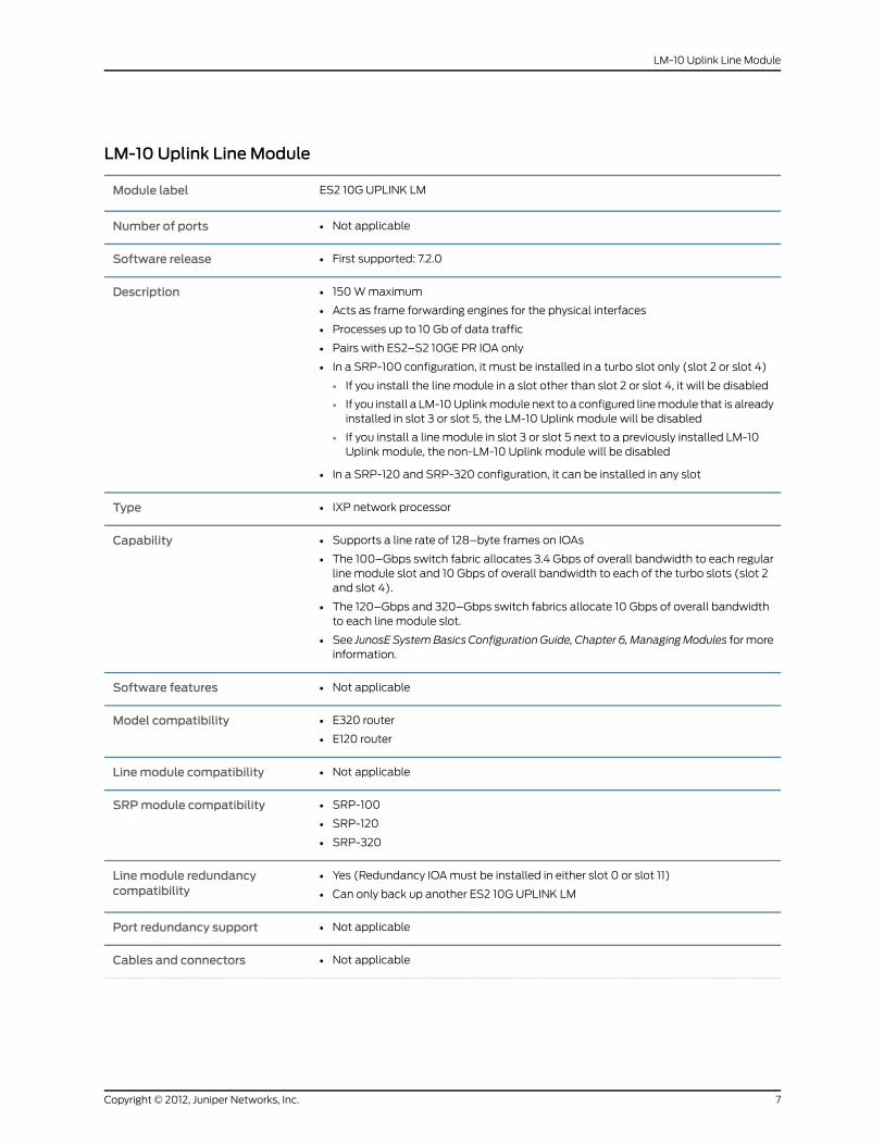
LM-10 Uplink LineModule
ES2 10G UPLINK LMModule label
• Not applicableNumber of ports
• First supported: 7.2.0Software release
• 150Wmaximum
• Acts as frame forwarding engines for the physical interfaces
• Processes up to 10 Gb of data traffic
• Pairs with ES2–S2 10GE PR IOA only
• In a SRP-100 configuration, it must be installed in a turbo slot only (slot 2 or slot 4)
• If you install the line module in a slot other than slot 2 or slot 4, it will be disabled
• If you install a LM-10Uplinkmodule next to a configured linemodule that is alreadyinstalled in slot 3 or slot 5, the LM-10 Uplink module will be disabled
• If you install a line module in slot 3 or slot 5 next to a previously installed LM-10Uplink module, the non-LM-10 Uplink module will be disabled
• In a SRP-120 and SRP-320 configuration, it can be installed in any slot
Description
• IXP network processorType
• Supports a line rate of 128–byte frames on IOAs
• The 100–Gbps switch fabric allocates 3.4 Gbps of overall bandwidth to each regularline module slot and 10 Gbps of overall bandwidth to each of the turbo slots (slot 2and slot 4).
• The 120–Gbps and 320–Gbps switch fabrics allocate 10 Gbps of overall bandwidthto each line module slot.
• See JunosE SystemBasics ConfigurationGuide, Chapter 6,ManagingModules formoreinformation.
Capability
• Not applicableSoftware features
• E320 router
• E120 router
Model compatibility
• Not applicableLinemodule compatibility
• SRP-100
• SRP-120
• SRP-320
SRPmodule compatibility
• Yes (Redundancy IOAmust be installed in either slot 0 or slot 11)
• Can only back up another ES2 10G UPLINK LM
Linemodule redundancycompatibility
• Not applicablePort redundancy support
• Not applicableCables and connectors
7Copyright © 2012, Juniper Networks, Inc.
LM-10 Uplink Line Module

When lit, LED indicates:
• OK (green)—Self-test passed
• FAIL (red)—Failure detected
• ONLINE (green)—Online with no alarms or errors
• REDUN (green)—Redundant card available
LEDs
• SeeMonitoring Modules in JunosE System Basics Configuration Guide, Chapter 6,Managing Modules.
Alarms, errors, and events
Copyright © 2012, Juniper Networks, Inc.8
E120 and E320 13.3.x Module Guide

LM-10 LineModule
ES2 10G LMModule label
• Not applicableNumber of ports
• First supported: 8.0.0Software release
• 198Wmaximum
• Acts as frame forwarding engines for the physical interfaces
• Processes up to 10 Gb of data traffic
• Pairs with ES2–S2 10GE PR IOA and ES2–S1 GE-8 IOA
• In a SRP-100 configuration, it must be installed in a turbo slot only (slot 2 or slot 4)
• If you install the line module in a slot other than slot 2 or slot 4, it will be disabled
• If you install the LM-10module next to a configured line module that is alreadyinstalled in slot 3 or slot 5, the LM-10module will be disabled
• If you install a line module in slot 3 or slot 5 next to a previously installed LM-10module, the non-LM-10module will be disabled
• In a SRP-120 and SRP-320 configuration, it can be installed in any slot
Description
• TFA ASICType
• Supports a line rate of 128–byte frames on IOAs
• The 100–Gbps switch fabric allocates 3.4 Gbps of overall bandwidth to each regularline module slot and 10 Gbps of overall bandwidth to each of the turbo slots (slot 2and slot 4).
• The 120–Gbps and 320–Gbps switch fabrics allocate 10 Gbps of overall bandwidthto each line module slot.
• See JunosE System Basics Configuration Guide, Chapter 6, ManagingModules for moreinformation.
Capability
• Not applicableSoftware features
• Not applicableLinemodule compatibility
• SRP-100
• SRP-120
• SRP-320
SRPmodule compatibility
• Yes (Redundancy IOAmust be installed in either slot 0 or slot 11)
• Can only back up another ES2 10G LM
Linemodule redundancycompatibility
• Not applicablePort redundancy support
• Not applicableCables and connectors
When lit, LED indicates:
• OK (green)—Self-test passed
• FAIL (red)—Failure detected
• ONLINE (green)—Online with no alarms or errors
• REDUN (green)—Redundant card available
LEDs
9Copyright © 2012, Juniper Networks, Inc.
LM-10 Line Module

• SeeMonitoring Modules in JunosE System Basics Configuration Guide, Chapter 6,Managing Modules.
Alarms, errors, and events
Copyright © 2012, Juniper Networks, Inc.10
E120 and E320 13.3.x Module Guide
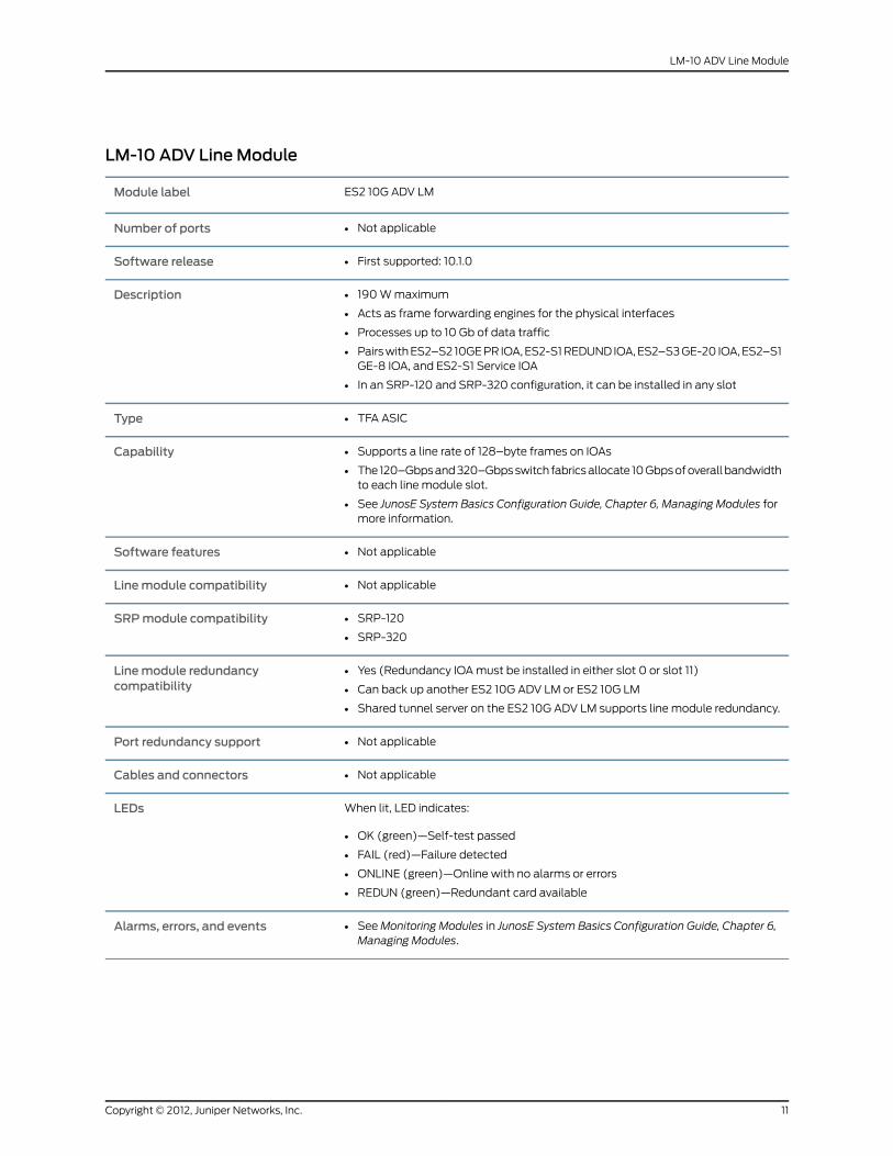
LM-10 ADV LineModule
ES2 10G ADV LMModule label
• Not applicableNumber of ports
• First supported: 10.1.0Software release
• 190Wmaximum
• Acts as frame forwarding engines for the physical interfaces
• Processes up to 10 Gb of data traffic
• PairswithES2–S2 10GEPR IOA,ES2-S1REDUND IOA,ES2–S3GE-20 IOA,ES2–S1GE-8 IOA, and ES2-S1 Service IOA
• In an SRP-120 and SRP-320 configuration, it can be installed in any slot
Description
• TFA ASICType
• Supports a line rate of 128–byte frames on IOAs
• The 120–Gbpsand320–Gbpsswitch fabricsallocate 10Gbpsofoverallbandwidthto each line module slot.
• See JunosE System Basics Configuration Guide, Chapter 6, Managing Modules formore information.
Capability
• Not applicableSoftware features
• Not applicableLinemodule compatibility
• SRP-120
• SRP-320
SRPmodule compatibility
• Yes (Redundancy IOAmust be installed in either slot 0 or slot 11)
• Can back up another ES2 10G ADV LM or ES2 10G LM
• Shared tunnel server on the ES2 10G ADV LM supports line module redundancy.
Linemodule redundancycompatibility
• Not applicablePort redundancy support
• Not applicableCables and connectors
When lit, LED indicates:
• OK (green)—Self-test passed
• FAIL (red)—Failure detected
• ONLINE (green)—Online with no alarms or errors
• REDUN (green)—Redundant card available
LEDs
• SeeMonitoring Modules in JunosE System Basics Configuration Guide, Chapter 6,Managing Modules.
Alarms, errors, and events
11Copyright © 2012, Juniper Networks, Inc.
LM-10 ADV Line Module

SRP-100Module
SRP-100Module label
SRP IOAIOA label
• Not applicableNumber of IOA ports
• First supported: 7.0.1Software release
• 75Wmaximum
• Switch route processor (100 Gbps)
• Performs systemmanagement, route table calculations andmaintenance,forwarding table computations, statistics processing, configuration storage, andother control plane functions
• Has 2 GB of memory
• Works with the SFM–100module to create a switch fabric
• Uses a PCMCIA nonvolatile storage (NVS) card to store the system's software andconfiguration files
• Must be installed only with SRP-100module and SFM–100modules
Description
• Not applicableCapability
• Not applicableSoftware features
• E320 routerModel compatibility
• ES2 4G LM
• ES2 10G UPLINK LM
• ES2 10G LM
Linemodule compatibility
• Cannot use with SRP-120module or SFM-120module
• Cannot use with SRP-320module or SFM-320module
SRPmodule compatibility
• Yes (ES2-S1 REDUND IOAmust be installed in either slot 0 or slot 11)Linemodule redundancycompatibility
• 1:1 redundancyModule redundancy support
• Not applicablePort redundancy support
• Not applicableCables and connectors
Copyright © 2012, Juniper Networks, Inc.12
E120 and E320 13.3.x Module Guide

Board-level LEDs:
• OK (green)—Self-test passed
• FAIL (red)—Failure detected
• ONLINE (green)—Online with no alarms or errors
• REDUN (green)—Module is the spare system controller, is up, and is ready to takethe role of the online system controller. When LED is not lit, module is not actingas the spare system controller.
• PA (green)—Power source on source A
• PB (green)—Power source on source B
• FO (green)—Fan OK
• FF (red)—Fan failure
• LK (green)—Ethernet link up
• AC (green)—Blinks when there is Ethernet activity (traffic) on link
Flash Card Port LEDs:
• 0 (green)—When lit, indicates slot is busy
• 1 (green)—When lit, indicates slot is busy
LEDs
• SeeMonitoring Modules in JunosE System Basics Configuration Guide, Chapter 6,Managing Modules.
Alarms, errors, and events
13Copyright © 2012, Juniper Networks, Inc.
SRP-100Module

SRP-120Module
SRP-120Module label
SRP IOAIOA label
• Not applicableNumber of IOA ports
• First supported: 8.2.0Software release
• 140Wmaximum
• Switch route processor (120 Gbps)
• Performssystemmanagement, route tablecalculationsandmaintenance, forwardingtable computations, statistics processing, configuration storage, and other controlplane functions
• Has 4 GB of memory
• Works with the SFM–120module to create a switch fabric
• The 120–Gbps fabric allocates 10 Gbps of overall bandwidth to each line moduleslot.
• Uses an ATA flash card to store the system's software and configuration files
• Two flash cards are required for operation
• Must be installed only with SRP-120module and SFM–120modules
Description
• Not applicableCapability
• Not applicableSoftware features
• E120 routerModel compatibility
• ES2 4G LM
• ES2 10G UPLINK LM
• ES2 10G LM
• ES2 10G ADV LM
Linemodule compatibility
• SRP-120
• Cannot use with SRP-100module or SFM-100module
• Cannot use with SRP-320module or SFM-320module
SRPmodule compatibility
• 1:1 redundancyModule redundancy support
• Not applicablePort redundancy support
• Not applicableCables and connectors
Copyright © 2012, Juniper Networks, Inc.14
E120 and E320 13.3.x Module Guide

Board-level LEDs:
• OK (green)—Self-test passed
• FAIL (red)—Failure detected
• ONLINE (green)—Online with no alarms or errors
• REDUN (green)—Module is the spare system controller, is up, and is ready to takethe role of the online system controller. When LED is not lit, module is not acting asthe spare system controller.
• PA (green)—Power source on source A
• PB (green)—Power source on source B
• FO (green)—Fan OK
• FF (red)—Fan failure
• LK (green)—Ethernet link up
• AC (green)—Blinks when there is Ethernet activity (traffic) on link
Flash Card Port LEDs:
• 0 (green)—When lit, indicates slot is busy
• 1 (green)—When lit, indicates slot is busy
LEDs
• SeeMonitoring Modules in JunosE System Basics Configuration Guide, Chapter 6,Managing Modules.
Alarms, errors, and events
15Copyright © 2012, Juniper Networks, Inc.
SRP-120 Module

SRP-320Module
SRP-320Module label
SRP IOAIOA label
• Not applicableNumber of IOA ports
• First supported: 7.3.0Software release
• 140Wmaximum
• Switch route processor (320 Gbps)
• Performssystemmanagement, route tablecalculationsandmaintenance, forwardingtable computations, statistics processing, configuration storage, and other controlplane functions
• Has 4 GB of memory
• Works with the SFM–320module to create a switch fabric
• The 320–Gbps fabric allocates 10 Gbps of overall bandwidth to each line moduleslot.
• Uses an ATA flash card to store the system's software and configuration files
• Two flash cards are required for operation
• Must be installed only with SRP-320module and SFM–320modules
Description
• Not applicableCapability
• Not applicableSoftware features
• E320 router
• E120 router
Model compatibility
• ES2 4G LM
• ES2 10G UPLINK LM
• ES2 10G LM
• ES2 10G ADV LM
Linemodule compatibility
• SRP-320
• Cannot use with SRP-100module or SFM-100module
• Cannot use with SRP-120module or SFM-120module
SRPmodule compatibility
• 1:1 redundancyModule redundancy support
• Not applicablePort redundancy support
• Not applicableCables and connectors
Copyright © 2012, Juniper Networks, Inc.16
E120 and E320 13.3.x Module Guide

Board-level LEDs:
• OK (green)—Self-test passed
• FAIL (red)—Failure detected
• ONLINE (green)—Online with no alarms or errors
• REDUN (green)—Module is the spare system controller, is up, and is ready to takethe role of the online system controller. When LED is not lit, module is not acting asthe spare system controller.
• PA (green)—Power source on source A
• PB (green)—Power source on source B
• FO (green)—Fan OK
• FF (red)—Fan failure
• LK (green)—Ethernet link up
• AC (green)—Blinks when there is Ethernet activity (traffic) on link
Flash Card Port LEDs:
• 0 (green)—When lit, indicates slot is busy
• 1 (green)—When lit, indicates slot is busy
LEDs
• SeeMonitoring Modules in JunosE System Basics Configuration Guide, Chapter 6,Managing Modules.
Alarms, errors, and events
17Copyright © 2012, Juniper Networks, Inc.
SRP-320Module

SFM-100Module
SFM-100Module label
• Not applicableIOA label
• Not applicableNumber of IOA ports
• First supported: 7.0.1Software release
• 40Wmaximum
• Switch fabric module (100 Gbps)
• Works with the SRP-100module to create a switch fabric
• Must be installed only with SRP-100module and SFM–100modules
Description
• Not applicableCapability
• Not applicableSoftware features
• E320 routerModel compatibility
• ES2 4G LM
• ES2 10G UPLINK LM
Linemodule compatibility
• SRP-100
• Cannot use with SRP-320module or SFM-320module
SRPmodule compatibility
• Yes (ES2-S1 REDUND IOAmust be installed in either slot 0 or slot 11)Linemodule redundancy compatibility
• N+1 redundancyModule redundancy support
• Not applicablePort redundancy support
• Not applicableCables and connectors
When lit, LED indicates:
• OK (green)—Self-test passed
• FAIL (red)—Failure detected
• ONLINE (green)—Online with no alarms or errors
• REDUN (green)—N+1 redundancy is enabled; 2 SRPs and 3 SFMsmust beinstalled andworking.When LED is unlit, one of the five fabric slices is downor not installed; N+1 redundancy is not enabled.
NOTE: When REDUN LED is on, the module may be removed withoutinterrupting service.
LEDs
• SeeMonitoring Modules in JunosE System Basics Configuration Guide,Chapter 6, Managing Modules.
Alarms, errors, and events
Copyright © 2012, Juniper Networks, Inc.18
E120 and E320 13.3.x Module Guide

SFM-120Module
SFM-120Module label
• Not applicableIOA label
• Not applicableNumber of IOA ports
• First supported: 8.2.0Software release
• 95Wmaximum
• Switch fabric module (120 Gbps)
• Works with the SRP-120module to create a switch fabric
• The 120–Gbps fabric allocates 10 Gbps of overall bandwidth to each linemodule slot.
• Must be installed only with SRP-120module and SFM–120modules
Description
• Not applicableCapability
• Not applicableSoftware features
• E120 routerModel compatibility
• ES2 4G LM
• ES2 10G UPLINK LM
• ES2 10G ADV LM
Linemodule compatibility
• SRP-120
• Cannot use with SRP-100module or SFM-100module
• Cannot use with SRP-320module or SFM-320module
SRPmodule compatibility
• N+1 redundancyModule redundancy support
• Not applicablePort redundancy support
• Not applicableCables and connectors
When lit, LED indicates:
• OK (green)—Self-test passed
• FAIL (red)—Failure detected
• ONLINE (green)—Online with no alarms or errors
• REDUN (green)—N+1 redundancy is enabled; 2 SRPs and 3 SFMsmust beinstalled andworking. When LED is unlit, one of the five fabric slices is down ornot installed; N+1 redundancy is not enabled.
NOTE: WhenREDUNLED is on, themodulemaybe removedwithout interruptingservice.
LEDs
• SeeMonitoringModules in JunosESystemBasics ConfigurationGuide, Chapter 6,Managing Modules.
Alarms, errors, and events
19Copyright © 2012, Juniper Networks, Inc.
SFM-120 Module

SFM-320Module
SFM-320Module label
• Not applicableIOA label
• Not applicableNumber of IOA ports
• First supported: 7.3.0Software release
• 95Wmaximum
• Switch fabric module (320 Gbps)
• Works with the SRP-320module to create a switch fabric
• The 320–Gbps fabric allocates 10 Gbps of overall bandwidth to each linemodule slot.
• Must be installed only with SRP-320module and SFM–320modules
Description
• Not applicableCapability
• Not applicableSoftware features
• E320 router
• E120 router
Model compatibility
• ES2 4G LM
• ES2 10G UPLINK LM
Linemodule compatibility
• SRP-320
• Cannot use with SRP-100module or SFM-100module
SRPmodule compatibility
• N+1 redundancyModule redundancy support
• Not applicablePort redundancy support
• Not applicableCables and connectors
When lit, LED indicates:
• OK (green)—Self-test passed
• FAIL (red)—Failure detected
• ONLINE (green)—Online with no alarms or errors
• REDUN (green)—N+1 redundancy is enabled; 2 SRPs and 3 SFMsmust beinstalled and working. When LED is unlit, one of the five fabric slices is downor not installed; N+1 redundancy is not enabled.
NOTE: WhenREDUNLED ison, themodulemaybe removedwithout interruptingservice.
LEDs
• SeeMonitoringModules in JunosESystemBasicsConfigurationGuide, Chapter 6,Managing Modules.
Alarms, errors, and events
Copyright © 2012, Juniper Networks, Inc.20
E120 and E320 13.3.x Module Guide

GE-4 IOA
ES2-S1 GE-4 IOAIOA label
• 4Number of IOA ports
• First supported: 7.0.1Software release
• 21 Wmaximum
• Half-height module
• See “Module and Slot Combinations” on page 73 for more information on combiningIOAs in a slot.
• Uses a range of small form-factor pluggable (SFP) transceivers to support differentmodes and cable lengths.
• Uses either optical or copper SFPs.
• The optical transceivers are 1000Base-SX, 1000Base-LX, and 1000Base-ZXcompliant.
• The copper transceivers are 1000Base-T compliant.
• Single-strand SFPs can be used. These SFPs work in pairs and require a matchingSFP at the opposite end of the Ethernet connection. For example, an SFP rated at TX1310, RX 1550must be paired with an SFP rated TX 1550, RX 1310 with the samemaximum operating range. See the following corresponding table (Single-strandSFPs Pairing) for more information.
Description
• Ethernet (IEEE 802.3x)
• 1000Base-SX/LX/ZX
Capability
• See “Ethernet IOAs” onpage49 for information about the layer 2 and layer 3 protocolsand applications that this module combination supports.
Software features
• E320 router
• E120 router
Model compatibility
• ES2 4G LMLinemodule compatibility
• SRP-100
• SRP-120
• SRP-320
SRPmodule compatibility
• Can be paired with an ES2 4G LM.
• Mustbe installed in thesame redundancygroupasanES24GLMandES2–S1REDUNDIOA combination.
Linemodule redundancycompatibility
• Not applicablePort redundancy support
• Maximum range is 100meters on CAT5 cable.Cables and connectors (copperSFP)
21Copyright © 2012, Juniper Networks, Inc.
GE-4 IOA

• Up to four LC-style fiber-optic connectors
• Transmit power:
• min: –9.5 dBm
• max: –3 dBm
• Receive input power:
• min: –20 dBm
• max: 0 dBm
• See the following corresponding table (SX Fiber Optic Cabling) for cablingrequirements.
• SeeE120andE320HardwareGuide, Chapter 5, Cabling theRouter formore information.
Cables and connectors(multimode [SX] )
• Up to four LC-style fiber-optic connectors
• Transmit power:
• min: –9.5 dBm
• max: –3 dBm
• Receive input power:
• min: –20 dBm
• max: –3 dBm
• See the following corresponding table (LX Fiber Optic Cabling) for cablingrequirements.
• SeeE120andE320HardwareGuide, Chapter 5, Cabling theRouter formore information.
Cables and connectors(single-mode [LX])
• Up to four LC-style fiber-optic connectors
• Transmit power:
• min: –4.5 dBm
• max: 0 dBm
• Receive input power:
• min: –35 dBm
• max: –22.5 dBm
• See the following corresponding table (LX40 Fiber Optic Cabling) for cablingrequirements.
• SeeE120andE320HardwareGuide, Chapter 5, Cabling theRouter formore information.
Cables and connectors(single-mode LX40)
• Up to four LC-style fiber-optic connectors
• Transmit power:
• min: –2 dBm
• max: 3 dBm
• Receive input power:
• min: –22 dBm
• max: –3 dBm
• See the following corresponding table (ZX Fiber Optic Cabling) for cablingrequirements.
• SeeE120andE320HardwareGuide, Chapter 5, Cabling theRouter formore information.
Cables and connectors(single-mode [ZX] )
Copyright © 2012, Juniper Networks, Inc.22
E120 and E320 13.3.x Module Guide
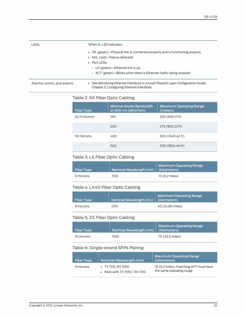
When lit, LED indicates:
• OK (green)—Physical link is connected properly and is functioning properly
• FAIL (red)—Failure detected
• Port LEDs:
• LK (green)—Ethernet link is up
• ACT (green)—Blinks when there is Ethernet traffic being received
LEDs
• SeeMonitoring Ethernet Interfaces in JunosE Physical Layer Configuration Guide,Chapter 5, Configuring Ethernet Interfaces.
Alarms, errors, and events
Table 2: SX Fiber Optic Cabling
MaximumOperating Range(meters)
Minimal Modal Bandwidthat 850 nm (MHz*km)Fiber Type
220 (656.17 ft)16062.5 microns
275 (902.23 ft)200
500 (1640.42 ft)40050microns
550 (1804.46 ft)500
Table 3: LX Fiber Optic Cabling
MaximumOperating Range(kilometers)NominalWavelength(nm)Fiber Type
10 (6.2 miles)13109microns
Table 4: LX40 Fiber Optic Cabling
MaximumOperating Range(kilometers)NominalWavelength(nm)Fiber Type
40 (24.85miles)13109microns
Table 5: ZX Fiber Optic Cabling
MaximumOperating Range(kilometers)NominalWavelength(nm)Fiber Type
70 (43.5 miles)155010microns
Table 6: Single-strand SFPs Pairing
MaximumOperating Range(kilometers)NominalWavelength (nm)Fiber Type
10 (6.2 miles), matching SFPmust havethe same operating range
• TX 1310, RX 1550
• Pairs with TX 1550 / RX 1310
9microns
23Copyright © 2012, Juniper Networks, Inc.
GE-4 IOA

Table 6: Single-strand SFPs Pairing (continued)
MaximumOperating Range(kilometers)NominalWavelength (nm)Fiber Type
10 (6.2 miles), matching SFPmust havethe same operating range
• TX 1550 / RX 1310
• Pairs with TX 1310, RX 1550
9microns
10 (6.2 miles), matching SFPmust havethe same operating range
• TX 1310, RX 1490
• Pairs with TX 1490 / RX 1310
9microns
10 (6.2 miles), matching SFPmust havethe same operating range
• TX 1490 / RX 1310
• Pairs with TX 1310, RX 1490
9microns
40 (24.85miles), matching SFPmusthave the same operating range
• TX 1310, RX 1550
• Pairs with TX 1550 / RX 1310
9microns
40 (24.85miles), matching SFPmusthave the same operating range
• TX 1550, RX 1310
• Pairs with TX 1310 / RX 1550
9microns
Copyright © 2012, Juniper Networks, Inc.24
E120 and E320 13.3.x Module Guide

GE-8 IOA
ES2-S1 GE-8 IOAIOA label
• 8Number of IOA ports
• First supported: 7.2.0Software release
• 32Wmaximum
• Gigabit Ethernet
• Half-height module
• See “Module and Slot Combinations” on page 73 for more information on combiningIOAs in a slot.
• Uses a range of small form-factor pluggable (SFP) transceivers to support differentmodes and cable lengths
• Uses either optical or copper SFPs.
• The optical transceivers are 1000Base-SX, 1000Base-LX, and 1000Base-ZXcompliant.
• The copper transceivers are 1000Base-T compliant.
• Single-strand SFPs can be used. These SFPs work in pairs and require a matchingSFP at the opposite end of the Ethernet connection. For example, an SFP rated at TX1310, RX 1550must be paired with an SFP rated TX 1550, RX 1310 with the samemaximum operating range. See the following corresponding table (Single-strandSFPs Pairing) for more information.
Description
• Ethernet (IEEE 802.3z)
• 1000Base-SX/LX/ZX
Capability
• See “Ethernet IOAs” onpage49 for informationabout the layer 2 and layer 3protocolsand applications that this module combination supports.
Software features
• E320 router
• E120 router
Model compatibility
• ES2 4G LM
• ES2 10G LM
• ES2 10G ADV LM
Linemodule compatibility
• SRP-100
• SRP-120
• SRP-320
SRPmodule compatibility
• Can be paired with an ES2 4G LM.
• Mustbe installed in thesameredundancygroupasanES24GLMandES2–S1REDUNDIOA combination.
Linemodule redundancycompatibility
• Not applicablePort redundancy support
• Maximum range is 100meters on CAT5 cable.Cables and connectors (copperSFP)
25Copyright © 2012, Juniper Networks, Inc.
GE-8 IOA

• One LC full duplex connector
• Transmit power:
• min: –9.5 dBm
• max: –3 dBm
• Receive input power:
• min: –20 dBm
• max: 0 dBm
• See the following corresponding table (SX Fiber Optic Cabling) for cablingrequirements.
• SeeE120andE320HardwareGuide,Chapter 5, Cabling theRouter formore information.
Cables and connectors(multimode [SX])
• One LC full duplex connector
• Transmit power:
• min: –9.5 dBm
• max: –3 dBm
• Receive input power:
• min: –20 dBm
• max: –3 dBm
• See the following corresponding table (LX Fiber Optic Cabling) for cablingrequirements.
• SeeE120andE320HardwareGuide,Chapter 5, Cabling theRouter formore information.
Cables and connectors(single-mode [LX])
• One LC full duplex connector
• Transmit power:
• min: –4.5 dBm
• max: 0 dBm
• Receive input power:
• min: –35 dBm
• max: –22.5 dBm
• See the following corresponding table (LX40 Fiber Optic Cabling) for cablingrequirements.
• SeeE120andE320HardwareGuide,Chapter 5, Cabling theRouter formore information.
Cables and connectors(single-mode LX40)
• One LC full duplex connector
• Transmit power:
• min: –2 dBm
• max: 3dBm
• Receive input power:
• min: –22 dBm
• max: –3 dBm
• See the following corresponding table (ZX Fiber Optic Cabling) for cablingrequirements.
• SeeE120andE320HardwareGuide,Chapter 5, Cabling theRouter formore information.
Cables and connectors(single-mode [ZX])
Copyright © 2012, Juniper Networks, Inc.26
E120 and E320 13.3.x Module Guide

Board-level LEDs:
• OK (green)—IOA is online and is functioning properly
• FAIL (red)—Failure detected
Port LEDs:
• LK (green)—Ethernet link is up
• ACT (green)—Blinks when Ethernet traffic is being received
LEDs
• SeeMonitoring Ethernet Interfaces in JunosE Physical Layer Configuration Guide,Chapter 5, Configuring Ethernet Interfaces.
Alarms, errors, and events
Table 7: SX Fiber Optic Cabling
MaximumOperating Range(meters)
Minimal Modal Bandwidthat 850 nm (MHz*km)Fiber Type
220 (656.17 ft)16062.5 microns
275 (902.23 ft)200
500 (1640.42 ft)40050microns
550 (1804.46 ft)500
Table 8: LX Fiber Optic Cabling
MaximumOperating Range(kilometers)NominalWavelength(nm)Fiber Type
10 (6.2 miles)13109microns
Table 9: LX40 Fiber Optic Cabling
MaximumOperating Range(kilometers)NominalWavelength(nm)Fiber Type
40 (24.85miles)13109microns
Table 10: ZX Fiber Optic Cabling
MaximumOperating Range(kilometers)NominalWavelength(nm)Fiber Type
70 (43.5 miles)155010microns
Table 11: Single-strand SFPs Pairing
MaximumOperating Range(kilometers)NominalWavelength (nm)Fiber Type
10 (6.2 miles), matching SFPmust havethe same operating range
• TX 1310, RX 1550
• Pairs with TX 1550 / RX 1310
9microns
27Copyright © 2012, Juniper Networks, Inc.
GE-8 IOA
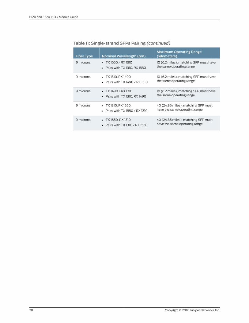
Table 11: Single-strand SFPs Pairing (continued)
MaximumOperating Range(kilometers)NominalWavelength (nm)Fiber Type
10 (6.2 miles), matching SFPmust havethe same operating range
• TX 1550 / RX 1310
• Pairs with TX 1310, RX 1550
9microns
10 (6.2 miles), matching SFPmust havethe same operating range
• TX 1310, RX 1490
• Pairs with TX 1490 / RX 1310
9microns
10 (6.2 miles), matching SFPmust havethe same operating range
• TX 1490 / RX 1310
• Pairs with TX 1310, RX 1490
9microns
40 (24.85miles), matching SFPmusthave the same operating range
• TX 1310, RX 1550
• Pairs with TX 1550 / RX 1310
9microns
40 (24.85miles), matching SFPmusthave the same operating range
• TX 1550, RX 1310
• Pairs with TX 1310 / RX 1550
9microns
Copyright © 2012, Juniper Networks, Inc.28
E120 and E320 13.3.x Module Guide

GE-20 IOA
ES2-S3 GE-20 IOAIOA label
• 20Number of IOA ports
• First supported: 9.0.0Software release
• 92Wmaximum
• Full-height module
• See “Module andSlot Combinations” on page 73 formore information on combining IOAsin a slot.
• Uses a range of small form-factor pluggable (SFP) transceivers to support differentmodes and cable lengths
• Uses either optical or copper SFPs.
• Theoptical transceiversare 1000Base-SX, 1000Base-LX, and 1000Base-ZXcompliant.
• The copper transceivers are 1000Base-T compliant and require a ferrite core to beattached around the Ethernet cable. Note that a ferrite bead is not required for a Finisartransceiver (FCLF8522P2BTL–J1).
• Single-strand SFPs can be used. These SFPs work in pairs and require a matching SFPat the opposite end of the Ethernet connection. For example, an SFP rated at TX 1310, RX1550mustbepairedwithanSFPratedTX1550,RX1310with thesamemaximumoperatingrange. See the following corresponding table (Single-strand SFPs Pairing) for moreinformation.
• Ina 100Gbps fabric configuration, theE320 router canaccommodateup to2combinationsof ES2 10G LMs and ES2-S3 GE-20 IOAs. Youmust install a combination in either of theturbo slots (slot 2 or slot 4). The 100Gbps allocates 10Gbps of overall bandwidth to eachof these slots.
• In a 120Gbps fabric configuration, theE120 router canaccommodateup to6combinationsof ES2 10G LMs and ES2-S3 GE-20 IOAs. You can install a combination in any of the linemodule slots, each of which are allocated 10 Gbps of overall bandwidth.
• In a 320 Gbps fabric configuration, the E320 router can accommodate up to 12combinations of ES2 10G LMs and ES2-S3 GE-20 IOAs. You can install a combination inany of the line module slots, each of which are allocated 10 Gbps of overall bandwidth.
Description
• Ethernet (IEEE 802.3x)
• 1000Base-SX/LX/ZX
Capability
• See “Ethernet IOAs” on page 49 for information about the layer 2 and layer 3 protocolsand applications that this module combination supports.
Software features
• E320 router
• E120 router
Model compatibility
• ES2 10G LM
• ES2 10G ADV LM
Linemodule compatibility
• SRP-100
• SRP-120
• SRP-320
SRPmodule compatibility
29Copyright © 2012, Juniper Networks, Inc.
GE-20 IOA

• Can be paired with an ES2 10G LM.
• Must be installed in the same redundancy group as an ES2 10G LM and ES2–S1 REDUNDIOA combination.
Linemodule redundancycompatibility
• Not applicablePort redundancy support
• Maximum range is 100meters on CAT5 cable.Cables and connectors(copper SFP)
• One LC full duplex connector
• Transmit power:
• min: –9.5 dBm
• max: –3 dBm
• Receive input power:
• min: –20 dBm
• max: 0 dBm
• See the following corresponding table (SX Fiber Optic Cabling) for cabling requirements.
• See E120 and E320 Hardware Guide, Chapter 5, Cabling the Router for more information.
Cables and connectors(multimode [SX])
• One LC full duplex connector
• Transmit power:
• min: –9.5 dBm
• max: –3 dBm
• Receive input power:
• min: –20 dBm
• max: –3 dBm
• See the following corresponding table (LX Fiber Optic Cabling) for cabling requirements.
• See E120 and E320 Hardware Guide, Chapter 5, Cabling the Router for more information.
Cables and connectors(single-mode [LX])
• One LC full duplex connector
• Transmit power:
• min: –4.5 dBm
• max: 0 dBm
• Receive input power:
• min: –35 dBm
• max: –22.5 dBm
• See the followingcorresponding table (LX40FiberOpticCabling) for cabling requirements.
• See E120 and E320 Hardware Guide, Chapter 5, Cabling the Router for more information.
Cables and connectors(single-mode LX40)
• One LC full duplex connector
• Transmit power:
• min: –2 dBm
• max: 3dBm
• Receive input power:
• min: –22 dBm
• max: –3 dBm
• See the following corresponding table (ZX Fiber Optic Cabling) for cabling requirements.
• See E120 and E320 Hardware Guide, Chapter 5, Cabling the Router for more information.
Cables and connectors(single-mode [ZX])
Copyright © 2012, Juniper Networks, Inc.30
E120 and E320 13.3.x Module Guide

Board-level LEDs:
• OK (green)—Physical link is connected properly and is functioning properly
• FAIL (red)—Failure detected
Port LEDs:
• LK (green)—Ethernet link is up
• ACT (green)—Blinks when there is Ethernet traffic being received
LEDs
• SeeMonitoring Ethernet Interfaces in JunosE Physical Layer Configuration Guide, Chapter 5,Configuring Ethernet Interfaces.
Alarms, errors, and events
Table 12: SX Fiber Optic Cabling
MaximumOperating Range(meters)
Minimal Modal Bandwidthat 850 nm (MHz*km)Fiber Type
220 (656.17 ft)16062.5 microns
275 (902.23 ft)200
500 (1640.42 ft)40050microns
550 (1804.46 ft)500
Table 13: LX Fiber Optic Cabling
MaximumOperating Range(kilometers)NominalWavelength(nm)Fiber Type
10 (6.2 miles)13109microns
Table 14: LX40 Fiber Optic Cabling
MaximumOperating Range(kilometers)NominalWavelength(nm)Fiber Type
40 (24.85miles)13109microns
Table 15: ZX Fiber Optic Cabling
MaximumOperating Range(kilometers)NominalWavelength(nm)Fiber Type
70 (43.5 miles)155010microns
Table 16: Single-strand SFPs Pairing
MaximumOperating Range(kilometers)NominalWavelength (nm)Fiber Type
10 (6.2 miles), matching SFPmust havethe same operating range
• TX 1310, RX 1550
• Pairs with TX 1550 / RX 1310
9microns
31Copyright © 2012, Juniper Networks, Inc.
GE-20 IOA

Table 16: Single-strand SFPs Pairing (continued)
MaximumOperating Range(kilometers)NominalWavelength (nm)Fiber Type
10 (6.2 miles), matching SFPmust havethe same operating range
• TX 1550 / RX 1310
• Pairs with TX 1310, RX 1550
9microns
10 (6.2 miles), matching SFPmust havethe same operating range
• TX 1310, RX 1490
• Pairs with TX 1490 / RX 1310
9microns
10 (6.2 miles), matching SFPmust havethe same operating range
• TX 1490 / RX 1310
• Pairs with TX 1310, RX 1490
9microns
40 (24.85miles), matching SFPmusthave the same operating range
• TX 1310, RX 1550
• Pairs with TX 1550 / RX 1310
9microns
40 (24.85miles), matching SFPmusthave the same operating range
• TX 1550, RX 1310
• Pairs with TX 1310 / RX 1550
9microns
Copyright © 2012, Juniper Networks, Inc.32
E120 and E320 13.3.x Module Guide
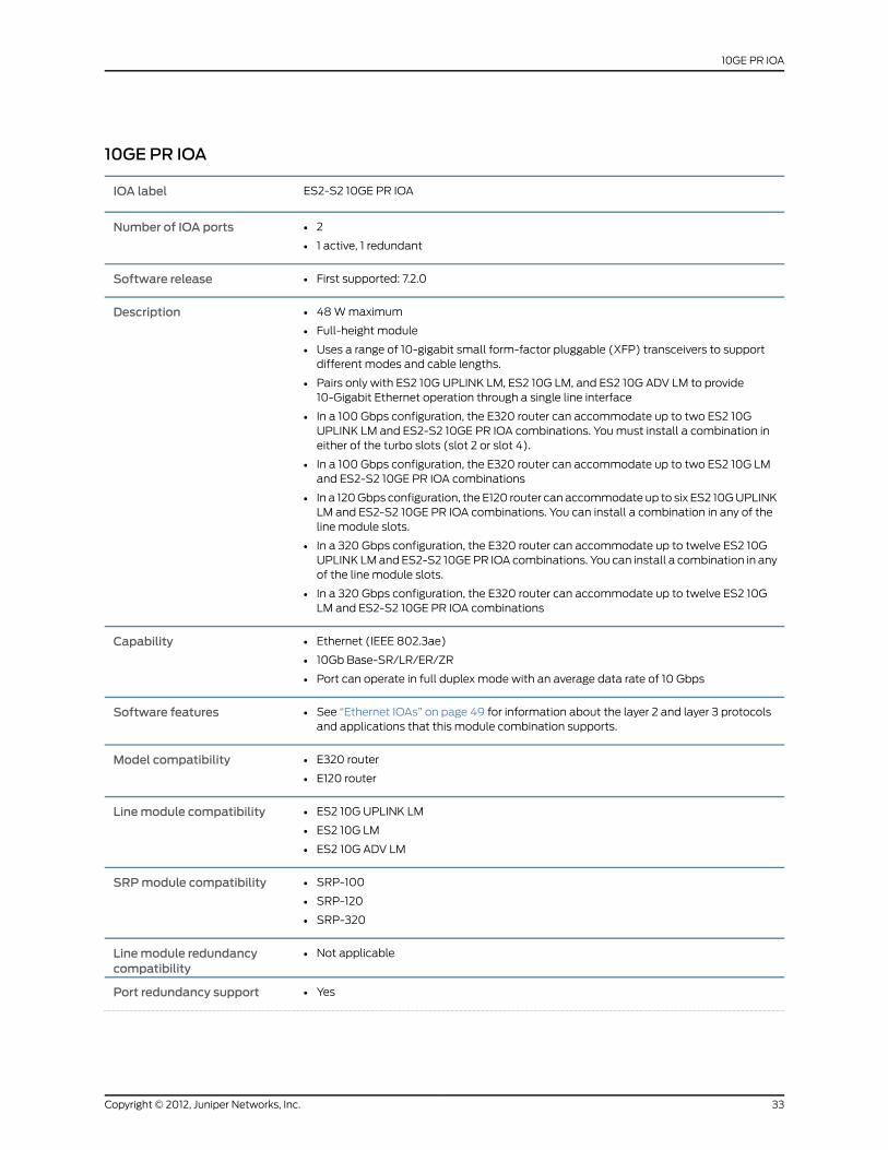
10GE PR IOA
ES2-S2 10GE PR IOAIOA label
• 2
• 1 active, 1 redundant
Number of IOA ports
• First supported: 7.2.0Software release
• 48Wmaximum
• Full-height module
• Uses a range of 10-gigabit small form-factor pluggable (XFP) transceivers to supportdifferent modes and cable lengths.
• Pairs only with ES2 10G UPLINK LM, ES2 10G LM, and ES2 10G ADV LM to provide10-Gigabit Ethernet operation through a single line interface
• In a 100 Gbps configuration, the E320 router can accommodate up to two ES2 10GUPLINK LM and ES2-S2 10GE PR IOA combinations. Youmust install a combination ineither of the turbo slots (slot 2 or slot 4).
• In a 100 Gbps configuration, the E320 router can accommodate up to two ES2 10G LMand ES2-S2 10GE PR IOA combinations
• In a 120Gbps configuration, the E120 router can accommodate up to six ES2 10GUPLINKLM and ES2-S2 10GE PR IOA combinations. You can install a combination in any of theline module slots.
• In a 320 Gbps configuration, the E320 router can accommodate up to twelve ES2 10GUPLINK LMand ES2-S2 10GEPR IOA combinations. You can install a combination in anyof the line module slots.
• In a 320 Gbps configuration, the E320 router can accommodate up to twelve ES2 10GLM and ES2-S2 10GE PR IOA combinations
Description
• Ethernet (IEEE 802.3ae)
• 10Gb Base-SR/LR/ER/ZR
• Port can operate in full duplex mode with an average data rate of 10 Gbps
Capability
• See “Ethernet IOAs” on page 49 for information about the layer 2 and layer 3 protocolsand applications that this module combination supports.
Software features
• E320 router
• E120 router
Model compatibility
• ES2 10G UPLINK LM
• ES2 10G LM
• ES2 10G ADV LM
Linemodule compatibility
• SRP-100
• SRP-120
• SRP-320
SRPmodule compatibility
• Not applicableLinemodule redundancycompatibility
• YesPort redundancy support
33Copyright © 2012, Juniper Networks, Inc.
10GE PR IOA

• One LC full duplex connector
• Transmit power:
• min: –7.3 dBm
• max: –1.0 dBm
• Receive input power:
• min: –9.9 dBm
• max: –1.0 dBm
• See the following corresponding table (SRFiberOpticCabling) for cabling requirements.
• See E120 and E320 Hardware Guide, Chapter 5, Cabling the Router for more information.
Cables and connectors(multimode [SR])
• One LC full duplex connector
• Transmit power:
• min: –8.2 dBm
• max: 0.5 dBm
• Receive input power:
• min: –14.4 dBm
• max: 0.5 dBm
• See the following corresponding table (LR FiberOptic Cabling) for cabling requirements.
• See E120 and E320 Hardware Guide, Chapter 5, Cabling the Router for more information.
Cables and connectors(single-mode [LR])
• One LC full duplex connector
• Transmit power:
• min: –4.7 dBm
• max: 4.0 dBm
• Receive input power:
• min: –15.8 dBm
• max: –1.0 dBm
• See the following corresponding table (ERFiberOptic Cabling) for cabling requirements.
• See E120 and E320 Hardware Guide, Chapter 5, Cabling the Router for more information.
Cables and connectors(single-mode [ER])
• One LC full duplex connector
• Transmit power:
• min: 0 dBm
• max: 4 dBm
• Receive input power:
• min: –24.0 dBm
• max: –7.0 dBm
• See the following corresponding table (ZRFiberOptic Cabling) for cabling requirements.
• See E120 and E320 Hardware Guide, Chapter 5, Cabling the Router for more information.
Cables and connectors(single-mode [ZR])
Copyright © 2012, Juniper Networks, Inc.34
E120 and E320 13.3.x Module Guide

Board-level LEDs:
• OK (green)—IOA online and is functioning properly
• FAIL (red)—Failure detected
Port LEDs:
• LK (green)—Ethernet link is up
• ACT (green)—Blinks when Ethernet traffic is being received
Port labels:
• W—Working port
• P—Protect port (LK blinks when active cable is attached even though it is not the activeworking port)
LEDs
• SeeMonitoringEthernet Interfaces in JunosEPhysical LayerConfigurationGuide, Chapter 5,Configuring Ethernet Interfaces.
Alarms, errors, and events
35Copyright © 2012, Juniper Networks, Inc.
10GE PR IOA

Table 17: SR Fiber Optic Cabling
MaximumOperating Range(meters)
MinimalModalBandwidthat850 nm (MHz*km)Fiber Type
26 (85.3 ft)16062.5 microns
33 (108.27 ft)200
66 (216.54 ft)40050microns
82 (269.03 ft)500
300 (984.25 ft)2000
Table 18: LR Fiber Optic Cabling
MaximumOperating Range(kilometers)NominalWavelength(nm)Fiber Type
10 (6.2 miles)13109microns
Table 19: ER Fiber Optic Cabling
MaximumOperating Range(kilometers)NominalWavelength(nm)Fiber Type
40 (24.85miles)15509microns
Table 20: ZR Fiber Optic Cabling
MaximumOperating Range(kilometers)NominalWavelength(nm)Fiber Type
80 (49.6 miles)15509microns
Copyright © 2012, Juniper Networks, Inc.36
E120 and E320 13.3.x Module Guide

OC3/STM1-8 ATM IOA
ES2-S1 OC3-8 STM1 ATM IOAIOA label
• 8Number of IOA ports
• First supported: 7.0.1Software release
• 50Wmaximum
• Half-height module
• See“ModuleandSlotCombinations”onpage73 formore informationoncombiningIOAs in a slot.
• Usesa rangeof small form-factor pluggable (SFP) transceivers to support differentmodes and cable lengths.
Description
• OC3/STM1
• ATM
Capability
• See “OCx/STMx ATM IOAs” on page 63 for information about the layer 2 and layer3 protocols and applications that this module combination supports.
Software features
• E320 router
• E120 router
Model compatibility
• ES2 4G LMLinemodule compatibility
• SRP-100
• SRP-120
• SRP-320
SRPmodule compatibility
• Can be paired with an ES2 4G LM.
• Must be installed in the same redundancy group as an ES2 4G LM and ES2–S1REDUND IOA combination.
Linemodule redundancycompatibility
• Not applicablePort redundancy support
• Up to eight LC full duplex connectors
• Transmit power:
• min: –20 dBm
• max: –14 dBm
• Center wavelength: 1310 nm
• Receive input power:
• min: –30 dBm
• max: –14 dBm
• Rated for 2 km (1.2 miles) over 62.5-micron core cable with an optical loss of 0-9dB or 50-micron core cable with an optical loss of 7 dB
• See E120 and E320 Hardware Guide, Chapter 5, Cabling the Router for moreinformation.
Cables and connectors(multimode)
37Copyright © 2012, Juniper Networks, Inc.
OC3/STM1-8 ATM IOA
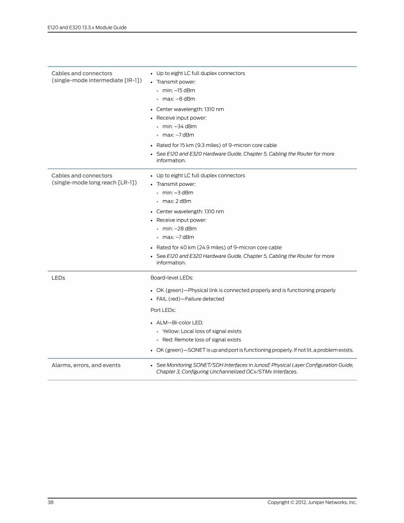
• Up to eight LC full duplex connectors
• Transmit power:
• min: –15 dBm
• max: –8 dBm
• Center wavelength: 1310 nm
• Receive input power:
• min: –34 dBm
• max: –7 dBm
• Rated for 15 km (9.3 miles) of 9-micron core cable
• See E120 and E320 Hardware Guide, Chapter 5, Cabling the Router for moreinformation.
Cables and connectors(single-mode intermediate [IR-1])
• Up to eight LC full duplex connectors
• Transmit power:
• min: –3 dBm
• max: 2 dBm
• Center wavelength: 1310 nm
• Receive input power:
• min: –28 dBm
• max: –7 dBm
• Rated for 40 km (24.9 miles) of 9-micron core cable
• See E120 and E320 Hardware Guide, Chapter 5, Cabling the Router for moreinformation.
Cables and connectors(single-mode long reach [LR-1])
Board-level LEDs:
• OK (green)—Physical link is connected properly and is functioning properly
• FAIL (red)—Failure detected
Port LEDs:
• ALM—Bi-color LED:
• Yellow: Local loss of signal exists
• Red: Remote loss of signal exists
• OK(green)—SONET isupandport is functioningproperly. If not lit, aproblemexists.
LEDs
• SeeMonitoring SONET/SDH Interfaces in JunosE Physical Layer Configuration Guide,Chapter 3, Configuring Unchannelized OCx/STMx Interfaces.
Alarms, errors, and events
Copyright © 2012, Juniper Networks, Inc.38
E120 and E320 13.3.x Module Guide

OC12/STM4-2 ATM IOA
ES2-S1 OC12-2 STM4 ATM IOAIOA label
• 2Number of IOA ports
• First supported: 7.0.1Software release
• 40Wmaximum
• Half-height module
• See“ModuleandSlotCombinations”onpage73 formore informationoncombiningIOAs in a slot.
• Usesa rangeof small form-factorpluggable (SFP) transceivers to supportdifferentmodes and cable lengths.
Description
• OC12/STM4
• ATM
Capability
• See “OCx/STMxATM IOAs” on page 63 for information about the layer 2 and layer3 protocols and applications that this module combination supports.
Software features
• E320 router
• E120 router
Model compatibility
• ES2 4G LMLinemodule compatibility
• SRP-100
• SRP-120
• SRP-320
SRPmodule compatibility
• Can be paired with an ES2 4G LM.
• Must be installed in the same redundancy group as an ES2 4G LM and ES2–S1REDUND IOA combination.
Linemodule redundancycompatibility
• Not applicablePort redundancy support
• Up to two LC full duplex connectors
• Transmit power:
• min: –15 dBm
• max: –8 dBm
• Center wavelength: 1310 nm
• Receive input power:
• min: –28 dBm
• max: –7 dBm
• Rated for 2 km (1.24 miles) of 9-micron core cable
• See E120 and E320 Hardware Guide, Chapter 5, Cabling the Router for moreinformation.
Cablesandconnectors(single-modeshort reach [SR])
39Copyright © 2012, Juniper Networks, Inc.
OC12/STM4-2 ATM IOA

• Up to two LC full duplex connectors
• Transmit power:
• min: –15 dBm
• max: –8 dBm
• Center wavelength: 1310 nm
• Receive input power:
• min: –28 dBm
• max: –7 dBm
• Rated for 15 km (9.3 miles) of 9-micron core cable
• See E120 and E320 Hardware Guide, Chapter 5, Cabling the Router for moreinformation.
Cablesandconnectors(single-modeintermediate [IR-1])
• Up to two LC full duplex connectors
• Transmit power:
• min: –3 dBm
• max: 2 dBm
• Center wavelength: 1310 nm
• Receive input power:
• min: –28 dBm
• max: –7 dBm
• Rated for 40 km (24.9 miles) of 9-micron core cable
• See E120 and E320 Hardware Guide, Chapter 5, Cabling the Router for moreinformation.
Cablesandconnectors(single-modelong reach [LR-1])
Board-level LEDs:
• OK (green)—Physical link is connected properly and is functioning properly
• FAIL (red)—Failure detected
Port LEDs:
• ALM—Bi-color LED:
• Yellow: Local loss of signal exists
• Red: Remote loss of signal exists
• OK (green)—SONET is up and port is functioning properly. If not lit, a problemexists.
LEDs
• SeeMonitoringSONET/SDH Interfaces in JunosEPhysical LayerConfigurationGuide,Chapter 3, Configuring Unchannelized OCx/STMx Interfaces.
Alarms, errors, and events
Copyright © 2012, Juniper Networks, Inc.40
E120 and E320 13.3.x Module Guide

OC12/STM4-2 POS IOA
ES2-S1 OC12-2 STM4 POS IOAIOA label
• 2Number of IOA ports
• First supported: 7.0.1Software release
• 30Wmaximum
• Half-height module
• See “Module and Slot Combinations” on page 73 for more information oncombining IOAs in a slot.
• Usesa rangeof small form-factorpluggable (SFP) transceivers tosupportdifferentmodes and cable lengths.
Description
• OC12/STM4
• POS
Capability
• See “OCx/STMxPOS IOAs” onpage66 for information about the layer 2 and layer3 protocols and applications that this module combination supports.
Software features
• E320 router
• E120 router
Model compatibility
• ES2 4G LMLinemodule compatibility
• SRP-100
• SRP-120
• SRP-320
SRPmodule compatibility
• Yes (Redundancy IOAmust be installed in either slot 0 or slot 11)Module redundancy support
• Can be paired with an ES2 4G LM.
• Must be installed in the same redundancy group as an ES2 4G LM and ES2–S1REDUND IOA combination.
Linemodule redundancycompatibility
• Not applicablePort redundancy support
• Up to two LC full duplex connectors
• Transmit power:
• min: –15 dBm
• max: –8 dBm
• Center wavelength: 1310 nm
• Receive input power:
• min: –28 dBm
• max: –7 dBm
• Rated for 2 km (1.24 miles) of 9-micron core cable
• See E120 and E320 Hardware Guide, Chapter 5, Cabling the Router for moreinformation.
Cablesandconnectors(single-modeshort reach [SR])
41Copyright © 2012, Juniper Networks, Inc.
OC12/STM4-2 POS IOA

• Up to two LC full duplex connectors
• Transmit power:
• min: –15 dBm
• max: –8 dBm
• Center wavelength: 1310 nm
• Receive input power:
• min: –28 dBm
• max: –7 dBm
• Rated for 15 km (9.3 miles) of 9-micron core cable
• See E120 and E320 Hardware Guide, Chapter 5, Cabling the Router for moreinformation.
Cablesandconnectors(single-modeintermediate [IR-1])
• Up to two LC full duplex connectors
• Transmit power:
• min: –3 dBm
• max: 2 dBm
• Center wavelength: 1310 nm
• Receive input power:
• min: –28 dBm
• max: –7 dBm
• Rated for 40 km (24.9 miles) of 9-micron core cable
• See E120 and E320 Hardware Guide, Chapter 5, Cabling the Router for moreinformation.
Cablesandconnectors(single-modelong reach [LR-1])
Board-level LEDs:
• OK (green)—Physical link is connected properly and is functioning properly
• FAIL (red)—Failure detected
Port LEDs:
• ALM—Bi-color LED:
• Yellow: Local loss of signal exists
• Red: Remote loss of signal exists
• OK (green)—SONET is up and port is functioning properly. If not lit, a problemexists.
LEDs
• SeeMonitoringSONET/SDH Interfaces in JunosEPhysical LayerConfigurationGuide,Chapter 3, Configuring Unchannelized OCx/STMx Interfaces.
Alarms, errors, and events
Copyright © 2012, Juniper Networks, Inc.42
E120 and E320 13.3.x Module Guide

OC48/STM16 POS IOA
ES2-S1 OC48 STM16 POS IOAIOA label
• 1Number of IOA ports
• First supported: 7.0.1Software release
• 30Wmaximum
• Half-height module
• See “Module and Slot Combinations” on page 73 for more information oncombining IOAs in a slot.
• Unchannelized, concatenated OC48/STM16 for POS
Description
• OC48/STM16
• HDLC framing
Capability
• See “OCx/STMxPOS IOAs” onpage66 for informationabout the layer 2 and layer3 protocols and applications that this module combination supports.
Software features
• E320 router
• E120 router
Model compatibility
• ES2 4G LMLinemodule compatibility
• SRP-100
• SRP-120
• SRP-320
SRPmodule compatibility
• Can be paired with an ES2 4G LM.
• Must be installed in the same redundancy group as an ES2 4G LM and ES2–S1REDUND IOA combination.
Linemodule redundancycompatibility
• Yes (Redundancy IOAmust be installed in either slot 0 or slot 11)Module redundancy support
• Not applicablePort redundancy support
• Up to one LC full duplex connector
• Transmit power:
• min: –10 dBm
• max: –3 dBm
• Center wavelength: 1310 nm
• Receive input power:
• min: –18 dBm
• max: –3 dBm
• Rated for 2 km (1.2 miles) of 9-micron core cable
• See E120 and E320 Hardware Guide, Chapter 5, Cabling the Router for moreinformation.
Cablesandconnectors(single-modeshort reach [SR-1])
43Copyright © 2012, Juniper Networks, Inc.
OC48/STM16 POS IOA
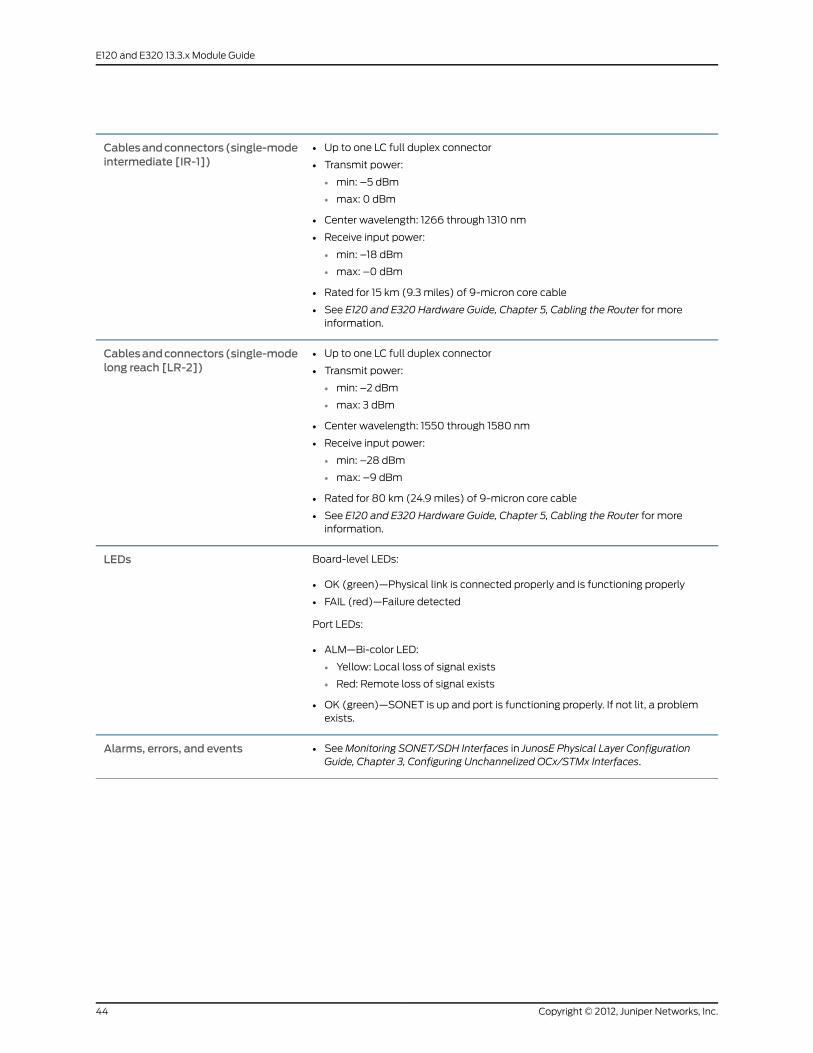
• Up to one LC full duplex connector
• Transmit power:
• min: –5 dBm
• max: 0 dBm
• Center wavelength: 1266 through 1310 nm
• Receive input power:
• min: –18 dBm
• max: –0 dBm
• Rated for 15 km (9.3 miles) of 9-micron core cable
• See E120 and E320 Hardware Guide, Chapter 5, Cabling the Router for moreinformation.
Cablesandconnectors(single-modeintermediate [IR-1])
• Up to one LC full duplex connector
• Transmit power:
• min: –2 dBm
• max: 3 dBm
• Center wavelength: 1550 through 1580 nm
• Receive input power:
• min: –28 dBm
• max: –9 dBm
• Rated for 80 km (24.9 miles) of 9-micron core cable
• See E120 and E320 Hardware Guide, Chapter 5, Cabling the Router for moreinformation.
Cablesandconnectors(single-modelong reach [LR-2])
Board-level LEDs:
• OK (green)—Physical link is connected properly and is functioning properly
• FAIL (red)—Failure detected
Port LEDs:
• ALM—Bi-color LED:
• Yellow: Local loss of signal exists
• Red: Remote loss of signal exists
• OK (green)—SONET is up and port is functioning properly. If not lit, a problemexists.
LEDs
• SeeMonitoring SONET/SDH Interfaces in JunosE Physical Layer ConfigurationGuide, Chapter 3, Configuring Unchannelized OCx/STMx Interfaces.
Alarms, errors, and events
Copyright © 2012, Juniper Networks, Inc.44
E120 and E320 13.3.x Module Guide

Redundancy IOA
ES2-S1 REDUND IOAIOA label
• 0Number of IOA ports
• First supported: 7.0.1Software release
• 10Wmaximum
• Full-height module
• Provides redundancy for line modules
• Inserted in slot 0 and 11 only
Description
• Provides switchover when a line module fails
• Provides N+1 redundancy for line modules
• When inserted in slot 0, provides redundancy for a failed line module inslots 1–5. When inserted in slot 11, provides redundancy for a failed linemodule in slots 12–16.
Capability
• See JunosE System Basics Configuration Guide, Chapter 6, ManagingModules.
Software features
• E320 router
• E120 router
Model compatibility
• ES2 4G LM
• ES2 10G UPLINK LM
• ES2 10G LM
• ES2 10G ADV LM
Linemodule compatibility
• SRP-100
• SRP-120
• SRP-320
SRPmodule compatibility
• Not applicableLinemodule redundancy compatibility
• Not applicablePort redundancy support
• Not applicableCables and connectors
• OK (green)—Self-test passed
• FAIL (red)—Failure detected
LEDs
• SeeMonitoring Modules in JunosE System Basics Configuration Guide,Chapter 6, Managing Modules.
Alarms, errors, and events
45Copyright © 2012, Juniper Networks, Inc.
Redundancy IOA

Service IOA
ES2-S1 SERVICE IOAIOA label
• 0Number of IOA ports
• First supported: 7.0.1Software release
• 10Wmaximum
• Full-height module
• Provides tunnel server functionality
• Pairs with associated line module to receive data from and transmit data toother line modules with ingress and egress ports
Description
• Tunneling
• Provides support for:
• Distance Vector Multicast Routing Protocol (DVMRP) tunnels, also knownas IP-in-IP tunnels
• Generic Routing Protocol (GRE) tunnels
• L2TP-dedicated tunnel server
• IP packet reassembly for tunnels
• MPLS over GRE
Capability
• See “Service IOA” on page 69 for information about the layer 2 and layer 3protocols and applications that this module combination supports.
Software features
• E320 router
• E120 router
Model compatibility
• ES2 4G LM
• ES2 10G ADV LM
Linemodule compatibility
• SRP-100
• SRP-120
• SRP-320
SRPmodule compatibility
• Not applicableModule redundancy support
• Not applicablePort redundancy support
• Not applicableCables and connectors
• OK (green)—Self-test passed
• FAIL (red)—Failure detected
• ONLINE (green)—Online with no alarms or errors
LEDs
• SeeMonitoring Tunnel-Service Interfaces in JunosE Physical Layer ConfigurationGuide, Chapter 6, Managing Tunnel-Service and IPSec-Service Interfaces.
Alarms, errors, and events
Copyright © 2012, Juniper Networks, Inc.46
E120 and E320 13.3.x Module Guide

SRP IOA
SRP IOAModule label
• Not applicableIOA label
• 3Number of IOA ports
• First supported: 7.0.1Software release
• 15Wmaximum
• Pairs with SRPmodule
• Interfaces with the SRPmodules through the system's midplane.
Description
• Ethernet (IEEE 802.3)
• 10/100Base-T
• RS-232
• Auxiliary port allows access to debug ports on a specific processor (SRPmodule,LM).
• External clock input accepts T1 or E1 signaling. Youmust configure the interface forT1 or E1. No additional configuration for a specific framingmode is required (forexample, SF/ESF).
• The BNC connector has a 75–Ohm load impedance.
• T1 inputs must be converted from a balanced 100–Ohm signal to an unbalanced75–Ohm signal by using a balun.
• Theminimum signal amplitude at the BNC connector is 400mV peak.
Capability
• Not applicableSoftware features
• E320 router
• E120 router
Model compatibility
• Not applicableLinemodule compatibility
• SRP-100
• SRP-120
• SRP-320
SRPmodule compatibility
• Not applicablePort redundancy support
• Terminal blocks
• Two dual-purpose BNC connectors (primary and secondary) for BITS timing clocksources (E1 or T1); 75–ohm E1 2.048–Mbps/T1 1.544–Mbps inputs terminating witha 120/75 ohm or 100/75 ohm balun
• One 10/100Base-T Ethernet management port with an RJ-45 connector
• Two RS-232 ports with DB-9 connectors for direct command line interface (CLI)and debug access
• See E120 and E320 Hardware Guide, Chapter 5, Cabling the Router for moreinformation.
Cables and connectors
• NoneLEDs
47Copyright © 2012, Juniper Networks, Inc.
SRP IOA

• SeeMonitoring Modules in JunosE System Basics Configuration Guide, Chapter 6,Managing Modules.
Alarms, errors, and events
Copyright © 2012, Juniper Networks, Inc.48
E120 and E320 13.3.x Module Guide

APPENDIX A
IOA Protocol Support
This appendix lists the layer 2 and layer 3 protocols and applications that IOAs support
in combination with the listed LM. IOAs are identified by their physical labels. See Table
1 on page 3 for a list of IOAs and their identifying labels.
The designation “not yet fully qualified” that appears in some tables in this appendix
indicates that support for the protocol or application on the specified IOA has not yet
been fully qualified by Juniper Networks. If you use a feature before it has been fully
qualified, it is your responsibility to ensure that it operates correctly in your targeted
configuration.
This appendix contains the following sections:
• Ethernet IOAs on page 49
• OCx/STMx ATM IOAs on page 63
• OCx/STMx POS IOAs on page 66
• Service IOA on page 69
Ethernet IOAs
Table 21: Ethernet IOAswith ES2 4G LM
ES2–S1 10GE IOA(withES24G LM)
ES2–S1GE-8 IOA(withES24G LM)
ES2–S1 GE-4 IOA (withES2 4G LM)Protocol or Application
YesYesYesAccepts traffic destined forGRE tunnels or DVMRP(IP-in-IP) tunnels
NoNoNoAPS/MSP
NoNoNoATM
NoNoNoBERT
NoYesYesBFD
YesYesYesBGP
49Copyright © 2012, Juniper Networks, Inc.

Table 21: Ethernet IOAswith ES2 4G LM (continued)
ES2–S1 10GE IOA(withES24G LM)
ES2–S1GE-8 IOA(withES24G LM)
ES2–S1 GE-4 IOA (withES2 4G LM)Protocol or Application
YesYesYesBGP/MPLS VPNs
NoNoNoBridged Ethernet
NoNoNoBridged IP
NoNoNoCisco HDLC
YesYesYesDHCP external server
YesYesYesDHCP local server
YesYesYesDHCPv6 local server
YesYesYesDVMRP and GREsupport—access side
Yes(over shared tunnel serverports)
Yes (over shared tunnel serverports)
Yes (over shared tunnelserver ports)
DVMRP and GREsupport—server side
YesYesYesDynamic interfaces
YesYesYesEthernet rawmodeencapsulation inMartini layer2 circuits
NoNoNoF4 OAM and F5 OAM (ATMadministration)
NoNoNoFDL (facilities data link)
NoNoNoFirewall
NoNoNoFrame Relay
YesYesYesICMP unreachable messagesfor packets reaching null 0interfaces with static routes
Yes (including fastreconnection of PPPoEsubscribers)
Yes (including fastreconnection of PPPoEsubscribers)
Yes (including fastreconnection of PPPoEsubscribers)
ICR
NoYesYesIEEE802.3ad linkaggregation
YesYesYesIEEE 802.3ah OAM link-faultmanagement
Copyright © 2012, Juniper Networks, Inc.50
E120 and E320 13.3.x Module Guide

Table 21: Ethernet IOAswith ES2 4G LM (continued)
ES2–S1 10GE IOA(withES24G LM)
ES2–S1GE-8 IOA(withES24G LM)
ES2–S1 GE-4 IOA (withES2 4G LM)Protocol or Application
YesYesYesIP
YesYesYesIP multicast
YesYesYesIP reassembly for tunneledpackets
NoNoNoIPsec
YesYesYesIPv6
YesYesYesIPv6multicast
YesYesYesIPv6 neighbor discovery
YesYesYesIS-IS
YesYesYesJ-Flow Statistics
NoNoNoL2TP/IPsec
YesYesYesL2TP over MPLS
YesYesYesLAC support—access side
YesYesYesLAC support—peer side
YesYesYesLNS support—peer side
NoNoNoLocal loopback
NoNoNoMDL (maintenancedata link)
Yes (not yet fully qualified)YesYes (not yet fully qualified)Mobile IP home agent
YesYesYesMPLS
YesYesYesMPLS L2VPNs over the LAGsconfiguredbetweencustomeredge (CE) and provider edge(PE) devices
NoYes (with fragmentation andreassembly; over MPL2TP onshared tunnel-server port;dynamic only)
Yes (with fragmentation andreassembly; overMPL2TP onshared tunnel-server port;dynamic only)
Multiclass multilink PPP
51Copyright © 2012, Juniper Networks, Inc.
Appendix A: IOA Protocol Support

Table 21: Ethernet IOAswith ES2 4G LM (continued)
ES2–S1 10GE IOA(withES24G LM)
ES2–S1GE-8 IOA(withES24G LM)
ES2–S1 GE-4 IOA (withES2 4G LM)Protocol or Application
NoNoNoMultilink Frame Relay
NoYes (with fragmentation andreassembly; over MPL2TP onshared tunnel-server port;dynamic only)
Yes (with fragmentation andreassembly; overMPL2TP onshared tunnel-server port;dynamic only)
Multilink PPP
NoNoNoNetwork Address Translation(NAT)
NoNoNoNBMA (multipoint ATM)
YesYesYesOSPF
YesYesYesPacket Mirroring
NoNoNoPacket over SONET
YesYesYesPPP
YesYesYesPPPoE
NoNoNoRemote loopback
YesYesYesRIP
NoNoNoStateful Line ModuleSwitchover
YesYesYesSubscriber interfaces (static)
YesYesYesSubscriber interfaces(dynamic)
YesYesYesS-VLAN subinterface with anuntagged C-VLAN ID inMartini circuits
YesYesYesTransparent bridging
Yes (shared only)Yes (shared only)Yes (shared only)Tunnel-server ports
NoYes (IOAmust be Revision 3and higher)
Yes (IOAmust be Revision 3and higher)
Unified ISSU
NoNoNoUnified ISSU forTunnel-server ports
Copyright © 2012, Juniper Networks, Inc.52
E120 and E320 13.3.x Module Guide
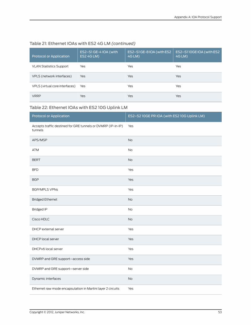
Table 21: Ethernet IOAswith ES2 4G LM (continued)
ES2–S1 10GE IOA(withES24G LM)
ES2–S1GE-8 IOA(withES24G LM)
ES2–S1 GE-4 IOA (withES2 4G LM)Protocol or Application
YesYesYesVLAN Statistics Support
YesYesYesVPLS (network interfaces)
YesYesYesVPLS(virtual core interfaces)
YesYesYesVRRP
Table 22: Ethernet IOAswith ES2 10GUplink LM
ES2–S2 10GE PR IOA (with ES2 10G Uplink LM)Protocol or Application
YesAccepts traffic destined for GRE tunnels or DVMRP (IP-in-IP)tunnels
NoAPS/MSP
NoATM
NoBERT
YesBFD
YesBGP
YesBGP/MPLS VPNs
NoBridged Ethernet
NoBridged IP
NoCisco HDLC
YesDHCP external server
YesDHCP local server
YesDHCPv6 local server
YesDVMRP and GRE support—access side
NoDVMRP and GRE support—server side
NoDynamic interfaces
YesEthernet rawmode encapsulation in Martini layer 2 circuits
53Copyright © 2012, Juniper Networks, Inc.
Appendix A: IOA Protocol Support
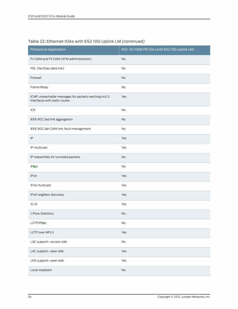
Table 22: Ethernet IOAswith ES2 10GUplink LM (continued)
ES2–S2 10GE PR IOA (with ES2 10G Uplink LM)Protocol or Application
NoF4 OAM and F5 OAM (ATM administration)
NoFDL (facilities data link)
NoFirewall
NoFrame Relay
YesICMP unreachable messages for packets reaching null 0interfaces with static routes
NoICR
NoIEEE 802.3ad link aggregation
NoIEEE 802.3ah OAM link-fault management
YesIP
YesIP multicast
NoIP reassembly for tunneled packets
NoIPsec
YesIPv6
YesIPv6multicast
YesIPv6 neighbor discovery
YesIS-IS
NoJ-Flow Statistics
NoL2TP/IPsec
YesL2TP over MPLS
NoLAC support—access side
YesLAC support—peer side
YesLNS support—peer side
NoLocal loopback
Copyright © 2012, Juniper Networks, Inc.54
E120 and E320 13.3.x Module Guide
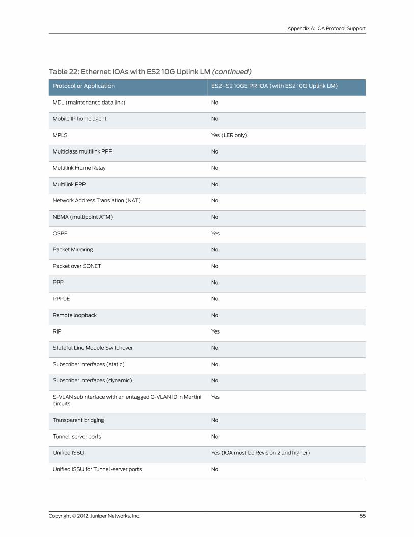
Table 22: Ethernet IOAswith ES2 10GUplink LM (continued)
ES2–S2 10GE PR IOA (with ES2 10G Uplink LM)Protocol or Application
NoMDL (maintenance data link)
NoMobile IP home agent
Yes (LER only)MPLS
NoMulticlass multilink PPP
NoMultilink Frame Relay
NoMultilink PPP
NoNetwork Address Translation (NAT)
NoNBMA (multipoint ATM)
YesOSPF
NoPacket Mirroring
NoPacket over SONET
NoPPP
NoPPPoE
NoRemote loopback
YesRIP
NoStateful Line Module Switchover
NoSubscriber interfaces (static)
NoSubscriber interfaces (dynamic)
YesS-VLAN subinterface with an untagged C-VLAN ID in Martinicircuits
NoTransparent bridging
NoTunnel-server ports
Yes (IOAmust be Revision 2 and higher)Unified ISSU
NoUnified ISSU for Tunnel-server ports
55Copyright © 2012, Juniper Networks, Inc.
Appendix A: IOA Protocol Support

Table 22: Ethernet IOAswith ES2 10GUplink LM (continued)
ES2–S2 10GE PR IOA (with ES2 10G Uplink LM)Protocol or Application
YesVLAN Statistics Support
NoVPLS (network interfaces)
NoVPLS (virtual core interfaces)
YesVRRP
Table 23: Ethernet IOAswith ES2 10G LM
ES2–S210GEPR IOA(withES2 10G LM)
ES2–S3 GE-20 IOA (withES2 10G LM)
ES2–S1GE-8 IOA(withES210G LM)Protocol or Application
YesYesYesAccepts traffic destined forGRE tunnels or DVMRP(IP-in-IP) tunnels
NoNoNoAPS/MSP
NoNoNoATM
NoNoNoBERT
NoNoYesBFD
YesYesYesBGP
YesYesYesBGP/MPLS VPNs
NoNoNoBridged Ethernet
NoNoNoBridged IP
NoNoNoCisco HDLC
YesYesYesDHCP external server
YesYesYesDHCP local server
YesYesYesDHCPv6 local server
YesYesYesDVMRP and GREsupport—access side
NoNoNoDVMRP and GREsupport—server side
YesYesYesDynamic interfaces
Copyright © 2012, Juniper Networks, Inc.56
E120 and E320 13.3.x Module Guide

Table 23: Ethernet IOAswith ES2 10G LM (continued)
ES2–S210GEPR IOA(withES2 10G LM)
ES2–S3 GE-20 IOA (withES2 10G LM)
ES2–S1GE-8 IOA(withES210G LM)Protocol or Application
YesYesYesEthernet rawmodeencapsulation inMartini layer2 circuits
NoNoNoF4 OAM and F5 OAM (ATMadministration)
NoNoNoFDL (facilities data link)
NoNoNoFirewall
NoNoNoFrame Relay
YesYesYesICMP unreachable messagesfor packets reaching null 0interfaces with static routes
Yes (except for fastreconnection of PPPoEsubscribers)
Yes (except for fastreconnection of PPPoEsubscribers)
Yes (except for fastreconnection of PPPoEsubscribers)
ICR
NoYesYesIEEE802.3ad linkaggregation
NoNoNoIEEE 802.3ah OAM link-faultmanagement
YesYesYesIP
YesYesYesIP multicast
NoNoNoIP reassembly for tunneledpackets
NoNoNoIPsec
YesYesYesIPv6
YesYesYesIPv6multicast
YesYesYesIPv6 neighbor discovery
YesYesYesIS-IS
YesYesYesJ-Flow Statistics
NoNoNoL2TP/IPsec
YesYesYesL2TP over MPLS
57Copyright © 2012, Juniper Networks, Inc.
Appendix A: IOA Protocol Support

Table 23: Ethernet IOAswith ES2 10G LM (continued)
ES2–S210GEPR IOA(withES2 10G LM)
ES2–S3 GE-20 IOA (withES2 10G LM)
ES2–S1GE-8 IOA(withES210G LM)Protocol or Application
YesYesYesLAC support—access side
YesYesYesLAC support—peer side
YesYesYesLNS support—peer side
NoNoNoLocal loopback
NoNoNoMDL (maintenancedata link)
NoNoNoMobile IP home agent
YesYesYesMPLS
YesYesYesMPLS L2VPNs over the LAGsconfiguredbetweencustomeredge (CE) and provider edge(PE) devices
NoNoNoMulticlass multilink PPP
NoNoNoMultilink Frame Relay
NoNoNoMultilink PPP
NoNoNoNetwork Address Translation(NAT)
NoNoNoNBMA (multipoint ATM)
YesYesYesOSPF
YesYesYesPacket Mirroring
NoNoNoPacket over SONET
YesYesYesPPP
YesYesYesPPPoE
NoNoNoRemote loopback
YesYesYesRIP
YesYesYesSubscriber interfaces (static)
Copyright © 2012, Juniper Networks, Inc.58
E120 and E320 13.3.x Module Guide
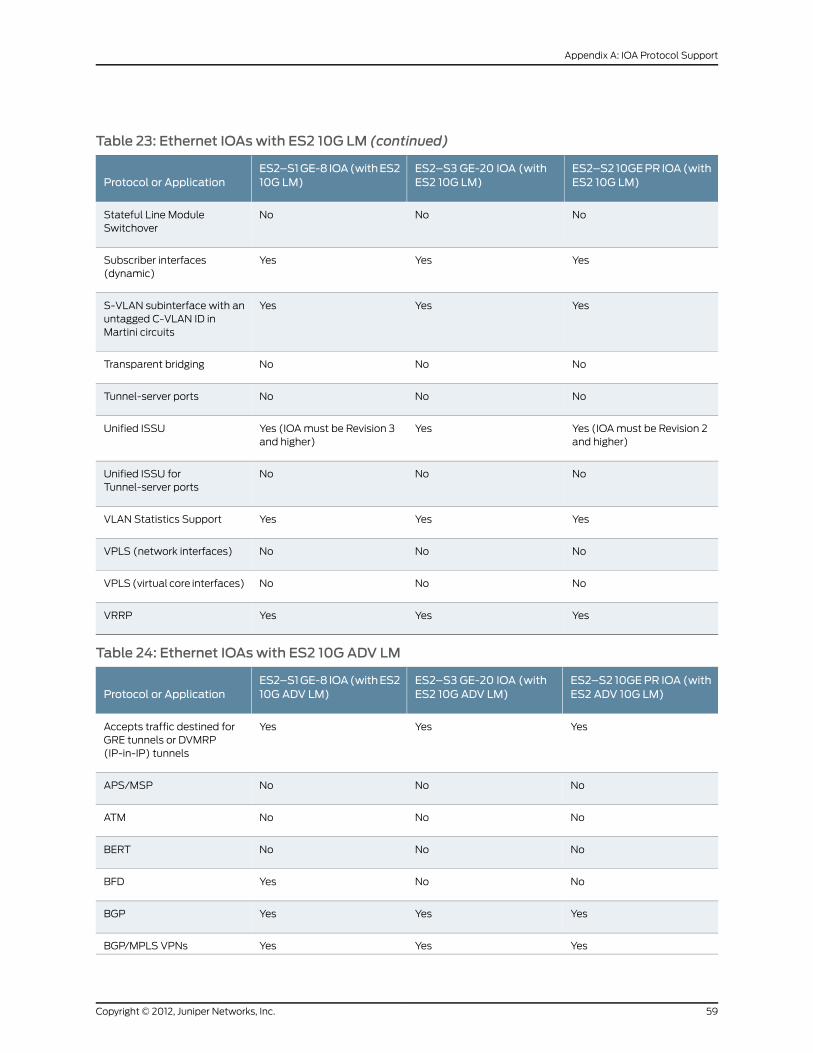
Table 23: Ethernet IOAswith ES2 10G LM (continued)
ES2–S210GEPR IOA(withES2 10G LM)
ES2–S3 GE-20 IOA (withES2 10G LM)
ES2–S1GE-8 IOA(withES210G LM)Protocol or Application
NoNoNoStateful Line ModuleSwitchover
YesYesYesSubscriber interfaces(dynamic)
YesYesYesS-VLAN subinterface with anuntagged C-VLAN ID inMartini circuits
NoNoNoTransparent bridging
NoNoNoTunnel-server ports
Yes (IOAmust be Revision 2and higher)
YesYes (IOAmust be Revision 3and higher)
Unified ISSU
NoNoNoUnified ISSU forTunnel-server ports
YesYesYesVLAN Statistics Support
NoNoNoVPLS (network interfaces)
NoNoNoVPLS(virtual core interfaces)
YesYesYesVRRP
Table 24: Ethernet IOAswith ES2 10G ADV LM
ES2–S2 10GEPR IOA (withES2 ADV 10G LM)
ES2–S3 GE-20 IOA (withES2 10G ADV LM)
ES2–S1GE-8 IOA(withES210G ADV LM)Protocol or Application
YesYesYesAccepts traffic destined forGRE tunnels or DVMRP(IP-in-IP) tunnels
NoNoNoAPS/MSP
NoNoNoATM
NoNoNoBERT
NoNoYesBFD
YesYesYesBGP
YesYesYesBGP/MPLS VPNs
59Copyright © 2012, Juniper Networks, Inc.
Appendix A: IOA Protocol Support

Table 24: Ethernet IOAswith ES2 10G ADV LM (continued)
ES2–S2 10GEPR IOA (withES2 ADV 10G LM)
ES2–S3 GE-20 IOA (withES2 10G ADV LM)
ES2–S1GE-8 IOA(withES210G ADV LM)Protocol or Application
NoNoNoBridged Ethernet
NoNoNoBridged IP
NoNoNoCisco HDLC
YesYesYesDHCP external server
YesYesYesDHCP local server
YesYesYesDHCPv6 local server
YesYesYesDVMRP and GREsupport—access side
NoNoNoDVMRP and GREsupport—server side
YesYesYesDynamic interfaces
YesYesYesEthernet rawmodeencapsulation inMartini layer2 circuits
NoNoNoF4 OAM and F5 OAM (ATMadministration)
NoNoNoFDL (facilities data link)
NoNoNoFirewall
NoNoNoFrame Relay
Yes (over shared tunnelservers only)
Yes (over shared tunnelservers only)
Yes (over shared tunnelservers only)
GRE support
YesYesYesICMP unreachable messagesfor packets reaching null 0interfaces with static routes
Yes (except for fastreconnection of PPPoEsubscribers)
Yes (except for fastreconnection of PPPoEsubscribers)
Yes (except for fastreconnection of PPPoEsubscribers)
ICR
NoYesYesIEEE802.3ad linkaggregation
NoNoNoIEEE 802.3ah OAM link-faultmanagement
Copyright © 2012, Juniper Networks, Inc.60
E120 and E320 13.3.x Module Guide

Table 24: Ethernet IOAswith ES2 10G ADV LM (continued)
ES2–S2 10GEPR IOA (withES2 ADV 10G LM)
ES2–S3 GE-20 IOA (withES2 10G ADV LM)
ES2–S1GE-8 IOA(withES210G ADV LM)Protocol or Application
YesYesYesIP
YesYesYesIP multicast
YesYesYesIP reassembly for tunneledpackets
NoNoNoIPsec
YesYesYesIPv6
YesYesYesIPv6multicast
YesYesYesIPv6 neighbor discovery
YesYesYesIS-IS
YesYesYesJ-Flow Statistics
NoNoNoL2TP/IPsec
YesYesYesL2TP over MPLS
YesYesYesLAC support—access side
YesYesYesLAC support—peer side
YesYesYesLNS support—peer side
NoNoNoLocal loopback
NoNoNoMDL (maintenancedata link)
NoNoNoMobile IP home agent
YesYesYesMPLS
YesYesYesMPLS L2VPNs over the LAGsconfiguredbetweencustomeredge (CE) and provider edge(PE) devices
NoNoNoMulticlass multilink PPP
NoNoNoMultilink Frame Relay
NoNoNoMultilink PPP
61Copyright © 2012, Juniper Networks, Inc.
Appendix A: IOA Protocol Support

Table 24: Ethernet IOAswith ES2 10G ADV LM (continued)
ES2–S2 10GEPR IOA (withES2 ADV 10G LM)
ES2–S3 GE-20 IOA (withES2 10G ADV LM)
ES2–S1GE-8 IOA(withES210G ADV LM)Protocol or Application
NoNoNoNetwork Address Translation(NAT)
NoNoNoNBMA (multipoint ATM)
YesYesYesOSPF
YesYesYesPacket Mirroring
NoNoNoPacket over SONET
YesYesYesPPP
YesYesYesPPPoE
NoNoNoRemote loopback
YesYesYesRIP
NoNoNoStateful Line ModuleSwitchover
YesYesYesSubscriber interfaces (static)
YesYesYesSubscriber interfaces(dynamic)
YesYesYesS-VLAN subinterface with anuntagged C-VLAN ID inMartini circuits
NoNoNoTransparent bridging
Yes (shared only)Yes (shared only)Yes (shared only)Tunnel-server ports
Yes (IOAmust be Revision 2and higher)
YesYes (IOAmust be Revision 3and higher)
Unified ISSU
Yes (shared only)Yes (shared only)Yes (shared only)Unified ISSU forTunnel-server ports
NoNoNoVPLS (network interfaces)
NoNoNoVPLS(virtual core interfaces)
YesYesYesVRRP
Copyright © 2012, Juniper Networks, Inc.62
E120 and E320 13.3.x Module Guide

OCx/STMx ATM IOAs
Table 25: OCx/STMx ATM IOA
ES2–S1 OC12–2 STM4 ATM IOAES2–S1 OC3–8 STM1 ATM IOAProtocol or Application
YesYesAccepts traffic destined for GRE tunnelsor DVMRP (IP-in-IP) tunnels
NoNoAPS/MSP
YesYesATM
NoNoBERT
NoYesBFD
YesYesBGP
YesYesBGP/MPLS VPNs
YesYesBridged Ethernet
YesYesBridged IP
NoNoCisco HDLC
YesYesDHCP external server
YesYesDHCP local server
YesYesDVMRP and GRE support—access side
Yes (over shared tunnel server ports)Yes (over shared tunnel server ports)DVMRP and GRE support—server side
YesYesDynamic interfaces
YesYesF4 OAM and F5 OAM (ATMadministration)
NoNoFDL (facilities data link)
NoNoFirewall
NoNoFrame Relay
NoNoICMPunreachablemessages forpacketsreaching null 0 interfaces with staticroutes
NoNoICR
63Copyright © 2012, Juniper Networks, Inc.
Appendix A: IOA Protocol Support
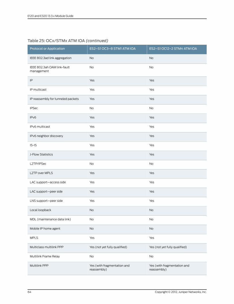
Table 25: OCx/STMx ATM IOA (continued)
ES2–S1 OC12–2 STM4 ATM IOAES2–S1 OC3–8 STM1 ATM IOAProtocol or Application
NoNoIEEE 802.3ad link aggregation
NoNoIEEE 802.3ah OAM link-faultmanagement
YesYesIP
YesYesIP multicast
YesYesIP reassembly for tunneled packets
NoNoIPSec
YesYesIPv6
YesYesIPv6multicast
YesYesIPv6 neighbor discovery
YesYesIS-IS
YesYesJ-Flow Statistics
NoNoL2TP/IPSec
YesYesL2TP over MPLS
YesYesLAC support—access side
YesYesLAC support—peer side
YesYesLNS support—peer side
NoNoLocal loopback
NoNoMDL (maintenance data link)
NoNoMobile IP home agent
YesYesMPLS
Yes (not yet fully qualified)Yes (not yet fully qualified)Multiclass multilink PPP
NoNoMultilink Frame Relay
Yes (with fragmentation andreassembly)
Yes (with fragmentation andreassembly)
Multilink PPP
Copyright © 2012, Juniper Networks, Inc.64
E120 and E320 13.3.x Module Guide

Table 25: OCx/STMx ATM IOA (continued)
ES2–S1 OC12–2 STM4 ATM IOAES2–S1 OC3–8 STM1 ATM IOAProtocol or Application
NoNoNetwork Address Translation (NAT)
NoNoNBMA (multipoint ATM)
YesYesOSPF
YesYesPacket Mirroring
NoNoPacket over SONET
YesYesPPP
YesYesPPPoE
NoNoRemote loopback
YesYesRIP
NoNoStateful Line Module Switchover
YesYesSubscriber interfaces (static)
YesYesSubscriber interfaces (dynamic)
YesYesTransparent bridging
Yes (shared only)Yes (shared only)Tunnel-server ports
YesYesUnified ISSU
NoNoUnified ISSU for Tunnel-server ports
YesYesVPLS (network interfaces)
YesYesVPLS (virtual core interfaces)
NoNoVRRP
65Copyright © 2012, Juniper Networks, Inc.
Appendix A: IOA Protocol Support

OCx/STMx POS IOAs
Table 26: OCx/STMx POS IOA
ES2–S1 OC12–2 STM4 POS IOAES2–S1 OC48 STM16 POS IOAProtocol or Application
YesYesAccepts traffic destined for GRE tunnelsor DVMRP (IP-in-IP) tunnels
NoNoAPS/MSP
NoNoATM
NoNoBERT
NoNoBFD
YesYesBGP
YesYesBGP/MPLS VPNs
NoNoBridged Ethernet
NoNoBridged IP
YesYesCisco HDLC
Yes (for POS uplink interfaces; POSaccess interfaces not yet fully qualified)
Yes (for POS uplink interfaces; POSaccess interfaces not yet fully qualified)
DHCP external server
Yes (for POS access interfaces; not yetfully qualified)
Yes (for POS access interfaces; not yetfully qualified)
DHCP local server
YesYesDVMRP and GRE support—access side
Yes (over shared tunnel server ports)YesDVMRP and GRE support—server side
NoNoDynamic interfaces
NoNoF4 OAM and F5 OAM (ATMadministration)
NoNoFDL (facilities data link)
NoNoFirewall
NoNoFrame Relay
NoNoICMPunreachablemessages forpacketsreaching null 0 interfaces with staticroutes
Copyright © 2012, Juniper Networks, Inc.66
E120 and E320 13.3.x Module Guide

Table 26: OCx/STMx POS IOA (continued)
ES2–S1 OC12–2 STM4 POS IOAES2–S1 OC48 STM16 POS IOAProtocol or Application
NoNoICR
NoNoIEEE 802.3ad link aggregation
NoNoIEEE 802.3ah OAM link-faultmanagement
YesYesIP
YesYesIP multicast
YesYesIP reassembly for tunneled packets
NoNoIPSec
YesYesIPv6
YesYesIPv6multicast
NoNoIPv6 neighbor discovery
YesYesIS-IS
YesYesJ-Flow Statistics
NoNoL2TP/IPSec
YesYesL2TP over MPLS
NoNoLAC support—access side
YesYesLAC support—peer side
YesYesLNS support—peer side
NoNoLocal loopback
NoNoMDL (maintenance data link)
NoNoMobile IP home agent
YesYesMPLS
NoNoMulticlass multilink PPP
NoNoMultilink Frame Relay
67Copyright © 2012, Juniper Networks, Inc.
Appendix A: IOA Protocol Support

Table 26: OCx/STMx POS IOA (continued)
ES2–S1 OC12–2 STM4 POS IOAES2–S1 OC48 STM16 POS IOAProtocol or Application
NoNoMultilink PPP
NoNoNetwork Address Translation (NAT)
NoNoNBMA (multipoint ATM)
YesYesOSPF
NoNoPacket Mirroring
YesYesPacket over SONET
YesYesPPP
NoNoPPPoE
NoNoRemote loopback
YesYesRIP
NoNoStateful Line Module Switchover
YesYesSubscriber interfaces (static)
NoNoSubscriber interfaces (dynamic)
NoNoTransparent bridging
Yes (shared only)Yes (shared only)Tunnel-server ports
YesYesUnified ISSU
NoNoUnified ISSU for Tunnel-server ports
NoNoVPLS (network interfaces)
YesYesVPLS (virtual core interfaces)
NoNoVRRP
Copyright © 2012, Juniper Networks, Inc.68
E120 and E320 13.3.x Module Guide

Service IOA
Table 27: Service IOA
ES2–S1 SERVICE IOAProtocol or Application
NoAccepts traffic destined for GRE tunnels or DVMRP (IP-in-IP) tunnels
NoAPS/MSP
NoATM
NoBERT
NoBFD
YesBGP
YesBGP/MPLS VPNs
NoBridged Ethernet
NoBridged IP
NoCisco HDLC
NoDHCP external server
NoDHCP local server
NoDVMRP and GRE support—access side
Yes (over dedicated tunnel server ports)DVMRP and GRE support—server side
NoDynamic interfaces
NoF4 OAM and F5 OAM (ATM administration)
NoFDL (facilities data link)
NoFirewall
NoFrame Relay
NoICMP unreachablemessages for packets reaching null 0 interfaces with staticroutes
NoICR
NoIEEE 802.3ad link aggregation
69Copyright © 2012, Juniper Networks, Inc.
Appendix A: IOA Protocol Support
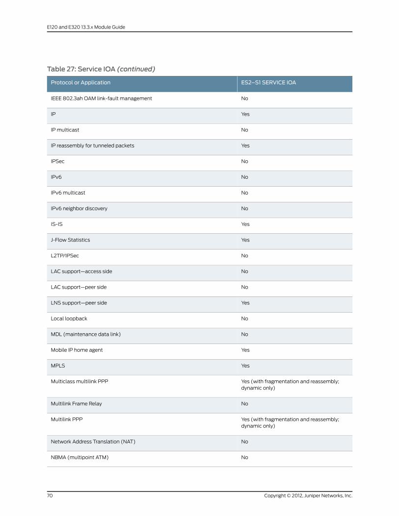
Table 27: Service IOA (continued)
ES2–S1 SERVICE IOAProtocol or Application
NoIEEE 802.3ah OAM link-fault management
YesIP
NoIPmulticast
YesIP reassembly for tunneled packets
NoIPSec
NoIPv6
NoIPv6multicast
NoIPv6 neighbor discovery
YesIS-IS
YesJ-Flow Statistics
NoL2TP/IPSec
NoLAC support—access side
NoLAC support—peer side
YesLNS support—peer side
NoLocal loopback
NoMDL (maintenance data link)
YesMobile IP home agent
YesMPLS
Yes (with fragmentation and reassembly;dynamic only)
Multiclass multilink PPP
NoMultilink Frame Relay
Yes (with fragmentation and reassembly;dynamic only)
Multilink PPP
NoNetwork Address Translation (NAT)
NoNBMA (multipoint ATM)
Copyright © 2012, Juniper Networks, Inc.70
E120 and E320 13.3.x Module Guide

Table 27: Service IOA (continued)
ES2–S1 SERVICE IOAProtocol or Application
YesOSPF
NoPacket Mirroring
NoPacket over SONET
NoPPP
NoPPPoE
NoRemote loopback
YesRIP
Yes (with ES2 4G LMs only)Stateful Line Module Switchover
Yes (over GRE tunnels only)Subscriber interfaces (static)
Yes (over GRE tunnels only)Subscriber interfaces (dynamic)
NoTransparent bridging
Yes (dedicated only)Tunnel-server ports
YesUnified ISSU
Yes (dedicated only)Unified ISSU for Tunnel-server ports
NoVPLS (network interfaces)
YesVPLS (virtual core interfaces)
NoVRRP
71Copyright © 2012, Juniper Networks, Inc.
Appendix A: IOA Protocol Support

Copyright © 2012, Juniper Networks, Inc.72
E120 and E320 13.3.x Module Guide

APPENDIX B
Module and Slot Combinations
Thisappendix listsmoduleand IOAslot combinationsandcontains the followingsections:
• Module Combinations on page 73
• IOA Slot Combinations on page 74
Module Combinations
Line modules can only be paired with specific IOA, SFM, and SRPmodules. See Table
28 on page 73 for valid combinations.
Table 28: Module Combinations
ES2 10G ADV LMES2 10G LMES2 10GUPLINKLMES2 4G LMModules
SRPModules
–√√√SRP-100
This module is onlysupported in theE320 router.
√√√√SRP-120
This module is onlysupported in theE120 router.
√√√√SRP-320
SFMModules
–√√√SFM-100
This module is onlysupported in theE320 router.
√√√√SFM-120
This module is onlysupported in theE120 router.
√√√√SFM-320
73Copyright © 2012, Juniper Networks, Inc.

Table 28: Module Combinations (continued)
ES2 10G ADV LMES2 10G LMES2 10GUPLINKLMES2 4G LMModules
IOAModules
–––√ES2-S1 GE-4
√√–√ES2-S1 GE-8
√√––ES2-S3 GE-20
–––√ES2-S1 10GE
√√√–ES2-S2 10GE PR
–––√ES2-S1 OC3-8 STM1 ATM
–––√ES2-S1 OC12-2 STM4 ATM
–––√ES2-S1 OC12-2 STM4 POS
–––√ES2-S1 OC48 STM16 POS
√√√√ES2-S1 REDUND
√––√ES2-S1 SERVICE
IOA Slot Combinations
Depending on the software release and IOA type, youmust install IOAs in certain slots
and bays combined with other IOAs in the same slot:
• Youmust insert some IOAs only in the upper bay or right bay (Adapter 0) of each IOA
module slot. If you insert one of these IOAs into a lower bay or left bay (Adapter 1) slot,
the line module diagnostics fail, an error message states that the bottom slot is not
supported for the currently installed software release, and the slot is disabled.
• If you insert an unrecognized IOA, such as an IOA that is not supported by a particular
software release, the line module diagnostics fail, an error is generated, and the slot
is disabled.
• If you remove an IOA and replace it with a different IOA in the same slot, an error
message states the mismatch and the slot is disabled.
• Full-height IOAs take up the entire slot (both Adapter 0 and Adapter 1).
For information about working with modules and IOAs, see JunosE System Basics
Configuration Guide, Chapter 6, Managing Modules. See Table 29 on page 75 for currently
available IOAs and the bays in which youmay insert them.
Copyright © 2012, Juniper Networks, Inc.74
E120 and E320 13.3.x Module Guide

Table 29: IOA Locations and Combinations
Hot-SwappingSupport
Combined withOther IOAs inSame Slot
Both BaysConcurrently
Lower/Left Bay(Adapter 1)
Upper/RightBay(Adapter 0)IOA
YesNoNoYesYesES2-S1 GE-4
YesYes (GE-8 whenpaired with ES24G LMor ES2 10GLM; GE-8,OC3/STM1, andOC12/STM4 IOAswhen paired withES2 4G LM)
YesYesYesES2-S1 GE-8
NoNot applicableNot applicableNot applicableYes
(Full-height IOA)
ES2-S3 GE-20
NoNot applicableNot applicableNot applicableYes
(Full-height IOA)
ES2-S1 10GE
NoNot applicableNot applicableNot applicableYes
(Full-height IOA)
ES2-S2 10GE PR
YesYes (GE-8,OC3/STM1, andOC12/STM4 IOAsonly)
YesYesYesES2-S1 OC3-8 STM1ATM
YesYes (GE-8,OC3/STM1, andOC12/STM4 IOAsonly)
YesYesYesES2-S1 OC12-2 STM4ATM
YesYes (GE-8,OC3/STM1, andOC12/STM4 IOAsonly)
YesYesYesES2-S1 OC12-2 STM4POS
YesNoNoYesYesES2-S1 OC48 STM16POS
NoNot applicableNot applicableNot applicableYes
(Full-height IOA)
ES2-S1 SERVICE
NoNot applicableNot applicableNot applicableYes
(Full-height IOA;slots 0 and 11only)
ES2-S1 REDUND
75Copyright © 2012, Juniper Networks, Inc.
Appendix B: Module and Slot Combinations

Copyright © 2012, Juniper Networks, Inc.76
E120 and E320 13.3.x Module Guide

APPENDIX C
Module Name Cross-ReferenceInformation
• Module Name Cross-Reference Information on page 77
Module Name Cross-Reference Information
Use Table 30 on page 77 to find the label name, software display name, andmodel
number of a module.
Table 30: Module Naming Reference
Model NumberSoftware Display NameLabel Name
SRPModules
ES2-SRP-IOASRP-IOASRP IOA
ES2-100G-SRPSRP-100SRP-100
ES2-120G-SRPSRP-120SRP-120
ES2-320G-SRPSRP-320SRP-320
SFMModules
ES2-100G-SFMSFM-100SFM-100
ES2-120G-SFMSFM-120SFM-120
ES2-320G-SFMSFM-320SFM-320
LineModules
ES2-4GS1-MODLM-4ES2 4G LM
ES2-10GUPS2-MODLM-10 UplinkES2 10G UPLINK LM
ES2-10GACS3-MODLM-10ES2 10G LM
ES2–10GACS4–MODLM-10 SES2 10G ADV LM
77Copyright © 2012, Juniper Networks, Inc.
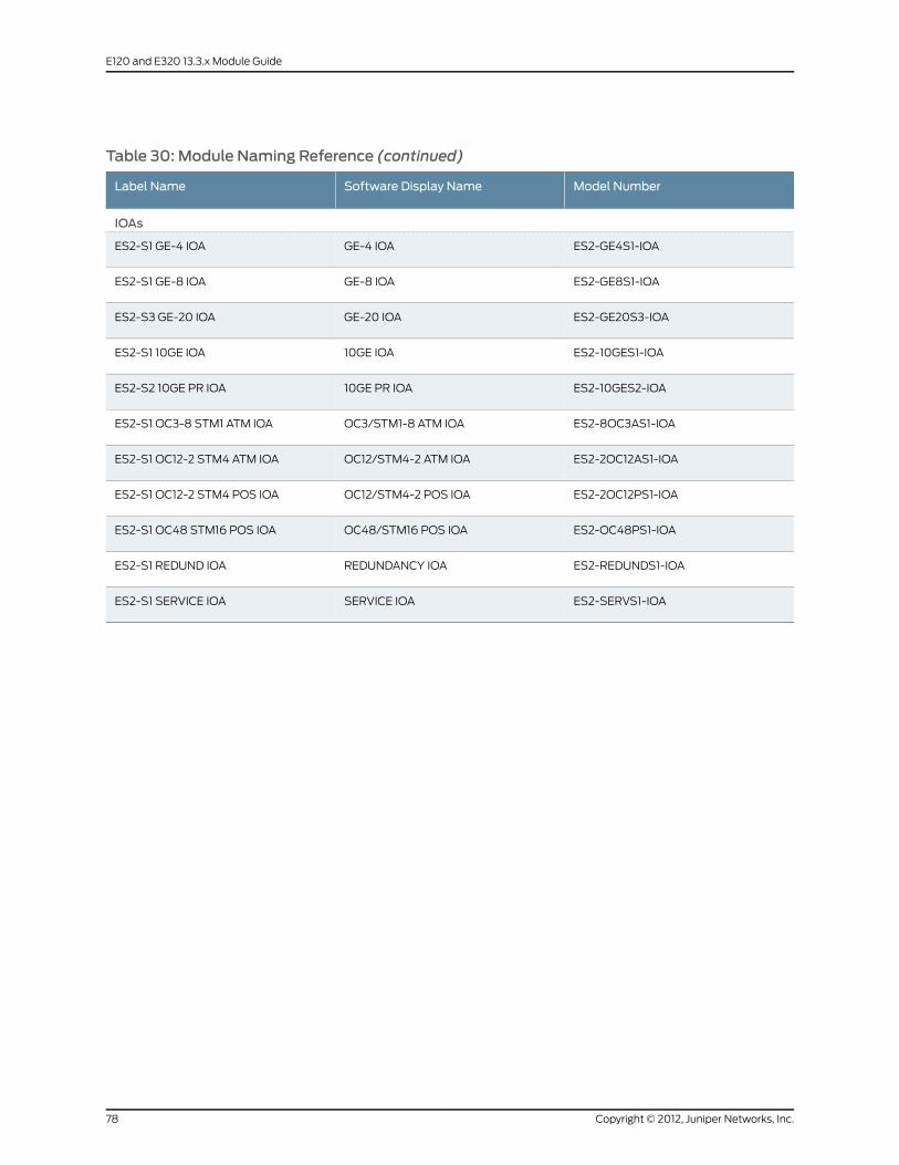
Table 30: Module Naming Reference (continued)
Model NumberSoftware Display NameLabel Name
IOAs
ES2-GE4S1-IOAGE-4 IOAES2-S1 GE-4 IOA
ES2-GE8S1-IOAGE-8 IOAES2-S1 GE-8 IOA
ES2-GE20S3-IOAGE-20 IOAES2-S3 GE-20 IOA
ES2-10GES1-IOA10GE IOAES2-S1 10GE IOA
ES2-10GES2-IOA10GE PR IOAES2-S2 10GE PR IOA
ES2-8OC3AS1-IOAOC3/STM1-8 ATM IOAES2-S1 OC3-8 STM1 ATM IOA
ES2-2OC12AS1-IOAOC12/STM4-2 ATM IOAES2-S1 OC12-2 STM4 ATM IOA
ES2-2OC12PS1-IOAOC12/STM4-2 POS IOAES2-S1 OC12-2 STM4 POS IOA
ES2-OC48PS1-IOAOC48/STM16 POS IOAES2-S1 OC48 STM16 POS IOA
ES2-REDUNDS1-IOAREDUNDANCY IOAES2-S1 REDUND IOA
ES2-SERVS1-IOASERVICE IOAES2-S1 SERVICE IOA
Copyright © 2012, Juniper Networks, Inc.78
E120 and E320 13.3.x Module Guide

APPENDIX D
Product Reclamation and RecyclingProgram
• Product Reclamation and Recycling Program on page 79
Product Reclamation and Recycling Program
Juniper Networks is committed to environmentally responsible behavior. As part of this
commitment, we continually work to comply with environmental standards such as the
European Union’sWaste Electrical and Electronic Equipment (WEEE) Directive and
Restriction of Hazardous Substances (RoHS) Directive.
Thesedirectivesandother similar regulations fromcountries outside theEuropeanUnion
regulate electronic waste management and the reduction or elimination of specific
hazardous materials in electronic products. TheWEEE Directive requires electrical and
electronics manufacturers to provide mechanisms for the recycling and reuse of their
products. The RoHS Directive restricts the use of certain substances that are commonly
found in electronicproducts today. Restricted substances includeheavymetals, including
lead, and polybrominatedmaterials. The RoHSDirective, with some exemptions, applies
to all electrical and electronic equipment.
In accordance with Article 11(2) of Directive 2002/96/EC (WEEE), products put on the
market after 13 August 2005 are marked with the following symbol or include it in their
documentation: a crossed-out wheeled waste bin with a bar beneath.
Juniper Networks provides recycling support for our equipment worldwide to comply
with theWEEE Directive. For recycling information, go to
http://www.juniper.net/environmental, and indicate the type of Juniper Networks
79Copyright © 2012, Juniper Networks, Inc.

equipment that you wish to dispose of and the country where it is currently located, or
contact your Juniper Networks account representative.
Products returned through our reclamation process are recycled, recovered, or disposed
of in a responsible manner. Our packaging is designed to be recycled and should be
handled in accordance with your local recycling policies.
Copyright © 2012, Juniper Networks, Inc.80
E120 and E320 13.3.x Module Guide

Copyright © 2012, Juniper Networks, Inc.

Juniper Networks, Junos, Steel-Belted Radius, NetScreen, and ScreenOS are registered trademarks of Juniper Networks, Inc. in the UnitedStates and other countries. The Juniper Networks Logo, the Junos logo, and JunosE are trademarks of Juniper Networks, Inc. All othertrademarks, service marks, registered trademarks, or registered service marks are the property of their respective owners.
Juniper Networks assumes no responsibility for any inaccuracies in this document. Juniper Networks reserves the right to change, modify,transfer, or otherwise revise this publication without notice.
Products made or sold by Juniper Networks or components thereof might be covered by one or more of the following patents that areowned by or licensed to Juniper Networks: U.S. Patent Nos. 5,473,599, 5,905,725, 5,909,440, 6,192,051, 6,333,650, 6,359,479, 6,406,312,6,429,706, 6,459,579, 6,493,347, 6,538,518, 6,538,899, 6,552,918, 6,567,902, 6,578,186, and 6,590,785.
E Series™ Broadband Services Routers E120 and E320 Module Guide, Release 13.3.xCopyright © 2012, Juniper Networks, Inc.All rights reserved.
Revision HistoryOctober 2012—FRS JunosE 13.3.x
The information in this document is current as of the date on the title page.
YEAR 2000 NOTICE
Juniper Networks hardware and software products are Year 2000 compliant. Junos OS has no known time-related limitations through theyear 2038. However, the NTP application is known to have some difficulty in the year 2036.
Copyright © 2012, Juniper Networks, Inc.