Embed Size (px)
Citation preview
2
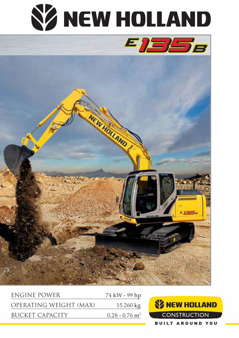
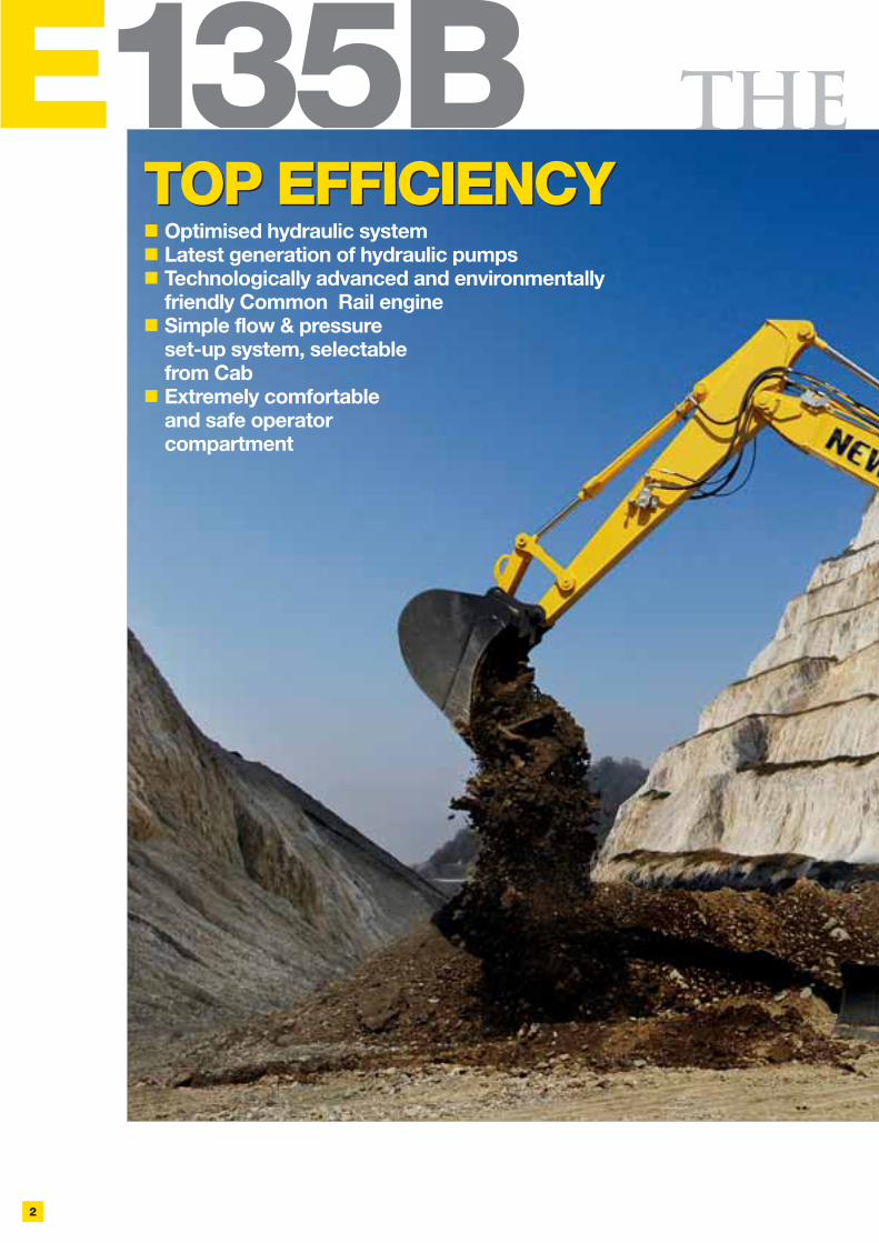
E135BTOP EFFICIENCYTOP EFFICIENCY
THE

3
SUPERIOR & SAFEDYNAM IC STABILITY
VERSATILITY
SUPERIOR & SAFEDYNAM IC STABILITY
The whole structure of E135B has beencom pletely redesigned, to guarantee a perfect
m atch with its high perform ances, by im provingthe position of it’s centre of gravity, by optim ising
the distribution of stress and by adopting high qualitysteel plates. In addition, the LC version undercarriage
contributes to im prove its overall stability.All this adds up to guarantee a m achine w ith
an excellent and safe dynam ic stabilitywhen working in any kind of job and on all types of ground.
PERFO RM AN CE
VERSATILITYCustom ers have the possibility to choose ex-Factory
their E135B am ong 4 versions:
* The blade width is tailored to the total width of them achine according to the dim ension of chosen shoes.

E135B
4
RESPECTING THE ENVIRONM ENTThe E135B is com pliant with European Directives concerning electrom agnetic com patibilityand noise level.The em issions of the new Stage IIIA M ITSUBISHI engine have beendram atically reduced and are, as shown below, m uch lower than standard requirem ents.
CO : 1.9, HC + NOx: 3.9, Particulate: 0.18 (*)...a real Environm entally Friendly m achine.(*) all data are expressed in g/kW h
TH E PO

5
This latest generation M ITSUBISHICom m on Rail Stage IIIA engine represents“state of the art” technology, designed toincrease perform ance and production whilstreducing fuel consum ption and pollution.At the sam e tim e noise is considerablyreduced.A durable, efficient, environm entallyfriendly and econom ic engine w hichcontributes to reduced operating costsand increased profits.
LOW EFFORT &PRECISE JOYSTICKSAll m achine m ovem ents can be sm oothly contolled by low
effort joystics... a real, effective Control of Pow er allowinglonger work tim es with less fatigue. The joystick illustrated issupplied as an option, together with rotating bucket circuit.
W ER O F CO N TRO L
Sensors are located in the pilot lines,sending signals to the on-board com puterthat are proportional to the operator’s useof the controls. These signals are m anagedtogether with engine r.p.m . to tune thequantity of hydraulic oil requested toguarantee extrem ely sm ooth and precisecontrols, excellent stability and steadyspeed during sim ultaneous operations.
ELECTRONICCONTROL
The E135B is equipped with two latestgeneration, low noise hydraulic pum ps ableto supply a very high flow: state-of-the-art pum ps, easy to control, prom pt toreact to all requirem ents and extrem elyquiet.
HYDRAULIC PUM PS
M ITSUBISHICOM M ON RAILENGINE STAGE IIIA

E135B
6
To obtain a Hydraulic Circuit which is m uch m ore efficient, controllable, fast, powerful and which consum esless fuel than the previous one, New Holland has been working on alm ost all com ponents.Starting from the state-of-the-art latest generation, low noise pum p to the redesigned control valve withadded second arm spool, high swing output torque and new working m ode selection functions.All these im provem ents, com bined with rigorous inspections to drastically reduce pressure loss in the wholecircuit, result in sm ooth and precise m ovem ents and better m achine controllability especially on operationsthat require com bined m ovem ents.These outstanding characteristics are further enhanced by the new H.A.O.A. Control.
EFFICIENCY AND CONTROLLABILITY
H ydrotronic Active Operation Aid is the m ost effective available com bination of an extrem ely advancedelectronic techology that provides a “just in tim e” com prehensive control of all m achine functions,and a deeply refined and sophisticated hydraulic system .H.A.O.A. continuously optim ises hydraulic output according to operator and job dem and, providingthe best m achine controllability, productivity, operator com fort and fuel savings.
H.A.O.A. (Hydrotronic Active Operation Aid)
N EW H YD RAU LIC CIRCU IT
AD VAN C

7
A.E.P. - (AdvancedElectronic Processor)A.E.P. is a new Electronic Processor that interacts with theoperator for selecting and m onitoring all m ain workingparam eters, m aintenance notifications, self diagnosis andoperating data storage.All this inform ation is displayed in the new m onitor, whichfeatures a larger back-lit, easier to read digital display andanalog gauges.Sim ply select the requested working m ode and A.E.P. presetsthe hydraulic system to accom plish the job in the easiest andm ost productive way:
- S m ode for norm al w orking operations- H m ode w hen m axim um pow er is requiredTwo additional m odes are available for special applicationsand to operate tools like breakers and crushers:
- A m ode adjusts the attachm ent circuitfor tools w hich require tw o w ay flow.
A dedicated switch on the dashboard, enables the operatorto select two pum ps oil flow
- B m ode for attachm ents featuring one way flow only.
Custom ers m ay choose to equip the m achines with optionalham m er & crusher and/or bucket rotation com plete circuits.
In both A and B working m odes, the operator, using the buttonson the m onitor, m ay adjust the flow by 10 l/m in steps and thepressure by 10 bars steps to perfectly m atch the param etersof the attachm ent being used.In addition, the operator can save to m em ory 9 com binationsof flow and pressure in both A and B working m odes, for a atotal of 18 com binations.
The newly redesigned Control Valve features a second spool dedicated to dipperstick operation.The m ovem ent “dipper out” is now achieved with a double flow, i.e., using the flow of the two pum ps.The “dipper in” m ovem ent is even faster because of the double pum p flow com bined with the“Conflux”, or recirculation of unused oil which is diverted from return to tank.A perfect com bination of speed, efficiency, precision and increased production.
D.O.C. (Dipperstick Optim ised Control)
ED H YD RAU LIC SYSTEM
European Standards state rules of thum b that do not allow free interpretation to each EuropeanCountry. In case of object handling operations, an excavator can be used only if certified bym anufacturer that it is equipped with all safety devices required by European Standards EN 474-5: 1996. New Holland , confirm ing its com m itm ent to grant high perform ances in an extrem ely safeenvironm ent, offers its custom ers the optional Object Handling Kit for m axim um operator confidence.
OBJECT HANDLING KIT

E135B
8
H IG H RE
Boom s and Arm s have been redesigned usingadvanced CAD (Com puter Aided Design) and FEM(Finite Elem ents M ethodology) System s to get higherstrength only in those areas w here stresses areconcentrated.These sophisticated design m ethodologies arecom bined with the m ost advanced productiontechnologies, providing high tensile steel plates thatare cut, assem bled and welded at the New Hollandplant, which has held the prestigious "Vision 2000"Quality Certification for m any years. The sam einnovative guidelines, to achieve Heavy Duty m axim umstrength together with outstanding torsional and flexionalresistance, are applied in design and m anufacture ofupper stucture and the undercarriage.
To p d esig n & pro d u
NEW BOOM& ARM
To further extend Arm s durabilityin tough applications, New Hollandoffers as optional a robust Armprotection.
9
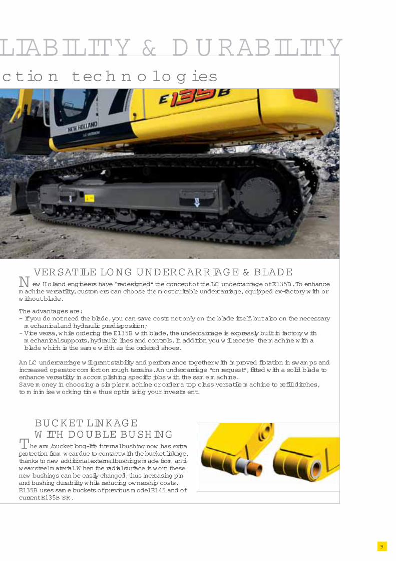
LIABILITY & D U RABILITYctio n tech n o lo g ies
The arm /bucket long-life internal bushing now has extraprotection from wear due to contact with the bucket linkage,thanks to new additional external bushings m ade from anti-wear steel m aterial. W hen the radial surface is worn thesenew bushings can be easily changed, thus increasing pinand bushing durability while reducing ownership costs.E135B uses sam e buckets of previous m odel E145 and ofcurrent E135B SR.
BUCKET LINKAGEW ITH DOUBLE BUSHING
VERSATILE LONG UNDERCARRIAGE & BLADEN ew Holland engineers have “redesigned” the concept of the LC undercarriage of E135B. To enhancem achine versatility, custom ers can choose the m ost suitable undercarriage, equipped ex-factory w ith orw ithout blade.
The advantages are:- If you do not need the blade, you can save costs not only on the blade itself, but also on the necessarym echanical and hydraulic predisposition;
- Vice versa, while ordering the E135B with blade, the undercarriage is expressly built in factory with m echanical supports, hydraulic lines and controls. In addition you will receive the m achine with a blade which is the sam e width as the ordered shoes.
An LC undercarriage will grant stability and perform ance together with im proved flotation in swam ps andincreased operator com fort on rough terrains. An undercarriage “on request”, fitted with a solid blade toenhance versatility in accom plishing specific jobs with the sam e m achine.Save m oney in choosing a sim pler m achine or order a top class versatile m achine to refill ditches,to m inim ise w orking tim e thus optim ising your investm ent.

10
E135B
NEW A. E. P. M ONITORThe newly designed A.E.P. M onitor,features analog gauges which provideone sight advice, regardless of theoperating environm ent.The digital Display Screen has beenenlarged to further enhance visibility.M aintenance inform ation is clearlydisplayed and the self-diagnostic functionprovides an early warning detection ofm alfunctions.Details of any previous breakdown orm alfunction are also stored.
NEWONE-HANDW INDSCREENOPENINGOne-touch lock releasesim plifies opening andclosing the front window,while a new m echanismm akes it lighter.
O PERATO
INSTRUM ENTLAYOUTIn-cab switches andcontrols have been m ovedto the right-hand side inan easy to reach and m oreergonom ic position, thusim proving operatorcom fort and convenience.
11
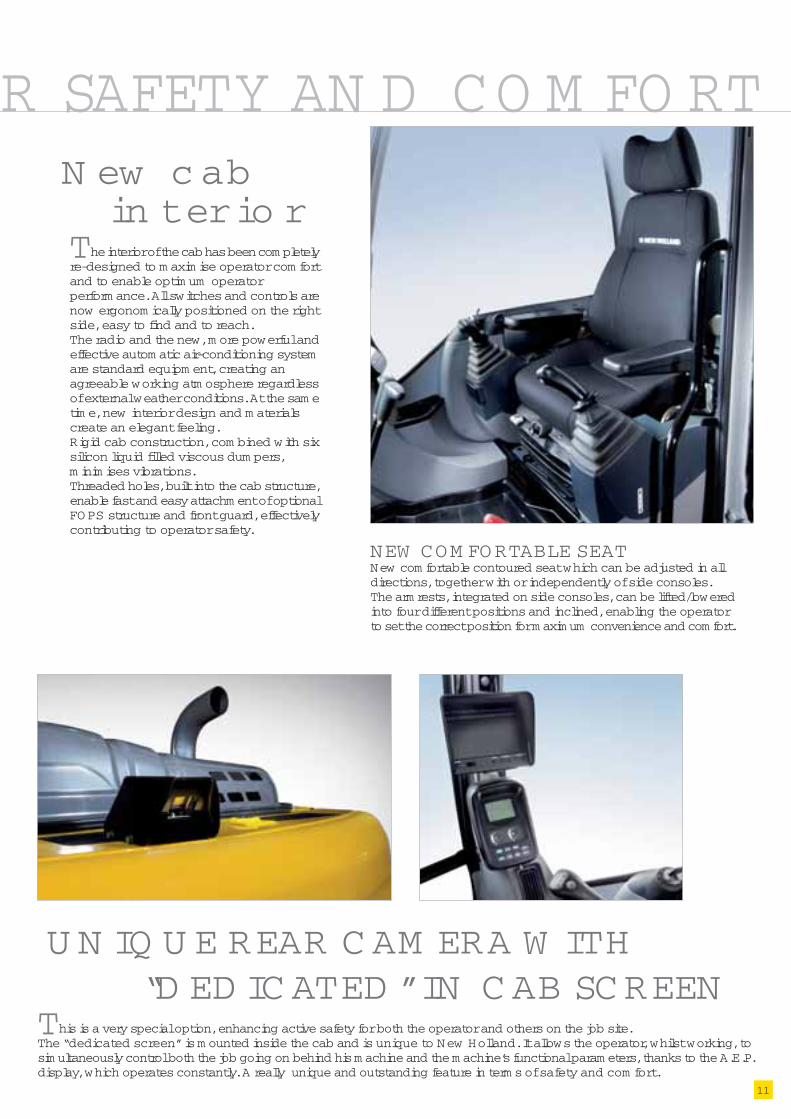
The interior of the cab has been com pletelyre-designed to m axim ise operator com fortand to enable optim um operatorperform ance. All switches and controls arenow ergonom ically positioned on the rightside, easy to find and to reach.The radio and the new, m ore powerful andeffective autom atic air-conditioning systemare standard equipm ent, creating anagreeable working atm osphere regardlessof external weather conditions. At the sam etim e, new interior design and m aterialscreate an elegant feeling.Rigid cab construction, com bined with sixsilicon liquid filled viscous dum pers,m inim ises vibrations.Threaded holes, built into the cab structure,enable fast and easy attachm ent of optionalFOPS structure and front guard, effectivelycontributing to operator safety.
N ew c abin terio r
U N IQ U E REAR C AM ERA W ITH“D ED IC ATED ” IN C AB SCREEN
This is a very special option, enhancing active safety for both the operator and others on the job site.The “dedicated screen” is m ounted inside the cab and is unique to New Holland. It allows the operator, whilst working, tosim ultaneously control both the job going on behind his m achine and the m achine’s functional param eters, thanks to the A.E.P.display, which operates constantly. A really unique and outstanding feature in term s of safety and com fort.
NEW COM FORTABLE SEATNew com fortable contoured seat which can be adjusted in alldirections, together with or independently of side consoles.The arm rests, integrated on side consoles, can be lifted/loweredinto four different positions and inclined, enabling the operatorto set the correct position for m axim um convenience and com fort.
R SAFETY AN D CO M FO RT
E135B
12
D ESIG N ED TO EFFECTIVELY CU TO PERATIN G CO STS
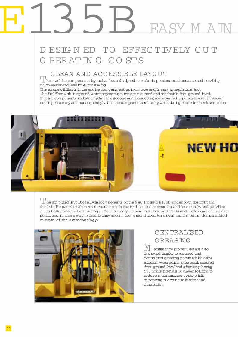
The sim plified layout of all vital com ponents of the New Holland E135B under both the right andthe left side panels m akes m aintenance m uch easier, less tim e consum ing and less costly, and providesm uch better access for servicing. There is plenty of room in all com partm ents and m ost com ponents arepositioned in such a way to enable easy access from ground level. An elegant and m odern design addedto state-of-the-art technology.
The m achine com ponents layout has been designed to m ake inspections, m aintenance and servicingm uch easier and less tim e-consum ing.The engine oil filter is in the engine com partm ent, spin-on type and is easy to reach from top.The fuel filter, with integrated water separator, is rem ote m ounted and reachable from ground level.Cooling com ponents (radiator, hydraulic oil cooler and intercooler) are m ounted in parallel for an increasedcooling efficiency and consequently raises the com ponents reliability whilst being easier to check and clean.
CLEAN AND ACCESSIBLE LAYOUT
M aintenance procedures are alsoim proved thanks to grouped andcentralised greasing points which allowall boom wear points to be easily greasedfrom ground level and after long lasting500 hours intervals. A clever solution toreduce m aintenance costs w hileim proving m achine reliability anddurability.
CENTRALISEDGREASING
EASY M AIN

13
TEN AN CE & SERVICEABILITYINSIDE CAB M AINTENANCEn Airconditioning filter, positioned under the seat, can be easily rem ovedwithout tools and from ground level, for easy cleaning.
n Detachable two-piece floorm at with handlesfor easy rem oval.A floor drain is located under the m at to facilitateinside cab cleaning.
The fuses are inside the cab,protected from dust and wateras well as easy to reach andcontrol.
FUSES
The tool box has been com pletely redesignedwith a side-opening panel and with thepredisposition to fit, on request, an electric,im m ersion type, fuel pum p with autom atic stopand alarm when the tank is full. The repositioningof batteries (left side, under cooling com ponents)and of fuses (inside the cab), generates extrafree space behind the cab for m ounting the airfilter and for an useful additional tool box.
TOOL BOX

14
E135BSPECIFIC ATIO N S
Net flywheel power (ECE R120).................................74 kW /99 hpRated.............................................................................2000 rpmM ake and m odel...................................M ITSUBISHI D04 FR-TAAType....................................diesel, Com m om Rail, direct injection,
turbocharged, aftercoolerDisplacem ent........................................................................4.25 lNum ber of cylinders....................................................................4Bore x Stroke..........................................................102 x 130 m mM axim um torque at 1600 rpm ...........................................375 NmElectronic engine rpm control dial type:“Auto-Idling” selector returns engine to m inim um rpm when allcontrols are in neutral position.The engine com plies with requirm ents set by European directive97/68/EC (2004/26/EC) Stage IIIA.
Voltage...................................................................................24 VAlternator...............................................................................70 AStarter m otor.........................................................................4 kWStandard m aintenance-free batteries...........................................2Capacity.............................................................................100 Ah
Higher capacity pum ps, to supply higher flow at lower rpm ;Redesigned M ain Control Valve, with added 2nd dipper spooland new Fail Safe Functions;H.A.O .A. (Hydrotronic Active O peration Aid) to get the besthydraulic output according to operator/application dem and;E.S.S.C. (Engine Speed Sensing Control) device, for total installedhydraulic power exploitation;D.O.C. (Dipper Optim ised Control) thanks to the 2nd dedicatedspool in the Control Valve and to the Conflux system ;A.E.P. (Advanced Electronic Processor) interacting with theoperator for selecting and m onitoring m ain working param eters,m aintenance program m es, self diagnosis and operating datastorage thanks to the new m onitor with a larger digital displayand analogical gauges;
Tw o w orking m odes:- S = for norm al digging operation;- H = when m axim um power is required;
Tw o Attachm ents m odes:- A = for attachm ents which require double pum p flow;- B = for attachm ents, such as breaker, featuring one way flow only.
Standard double pum p flow device and Diverter Valveautom atically actuated while selecting A;Pipe pressure discharge push button to facilitate toolingchangeover without piping oil leakage;Super Fine hydraulic filter (8 m icron) to grant perfect oil filtration,contributing to increase oil change interval
M ain pum ps:Two variable displacem ent axial piston pum psPum ps autom atically revert to zero with controls in neutralM axim um delivery......................................................2 x 130 l/m inPilot circuit gear type pum pM axim um delivery.............................................................20 l/m inM axim um operating pressure:Equipm ent......................................................................34.3 M PaSwing.............................................................................28.0 M PaTravel..............................................................................34.3 M PaPilot circuit........................................................................5.0 M Pa
Hydraulic cyinders.....................................................double effect-Lifting (2) - Bore and stroke.................................110 x 1030 m m-Penetration (1) - Bore and stroke........................115 x 1120 m m-Bucket (1) - Bore and stroke...................................95 x 905 m m-Positioner (only triple articulation)Bore and stroke......................................................95 x 825 m m
-Blade cylinders (2)................................................110 x 220 m m
Type..........................................................hydrostatic, two-speedTravel m otors..................2, axial piston type, double displacem entBrakes.............................oil bath disc type, autom atically applied
and hydraulically releasedFinal drives...........oil bath, planetary reductionGradeability (continuous)................................................70% (35°)Travel speedsLow ............................................................................0 - 3.4 km /hHigh...........................................................................0 - 5.5 km /hDrawbar pull.......................................................................138 kN“Autom atic Dow nShift” device: to m ove travel m otors to m axim umdisplacem ent position with selector on “high speed” position whengreater traction is required.
Swing m otor.........................................................axial piston typeSwing brake...................................................autom atic disc typeFinal drive...........................................oil bath, planetary reductionSwing Ring.................................................................oil bath typeSwing Speed...................................................................10.5 rpm
Transparent cab roof.Standard autom atic conditioning.Controls..............................................................................pilotedTwo cross pattern levers actuate all equipm ent m ovem ents andupperstructure swing.Two pedals with hand levers control all track m ovem ents, counter-rotation included.A safety lever com pletely neutralizes the piloting circuit.
X-fram e undercarriage design.Heavy duty track chain with sealed bushings.
LCTrack rollers (each side) 7Carrier rollers (each side) 2Length of track on ground 3045 m mGauge 1990 m mShoes (m m ) 500 - 600
700 - 800
litresLube oil..................................................................................18.5Coolant..................................................................................14.0Fuel tank..............................................................................238.0Hydraulic system ..................................................................140.0Swing drive gear.......................................................................1.7Final drive (each).......................................................................2.1
SW ING
CAB AND CO NTRO LS
UNDERCARRIAGE
CAPACITIES
ENGINE STAGE IIIA
ELECTRICAL SYSTEM
HYDRAULIC SYSTEM
TRANSM ISSIO N

1715
2100 2450 2950 2100 2450 2950 2100 2450 2950 2100 2450 2950
E135B E135B
X
X
Note: standard and optional equipm ent m ay vary by country. Consult your NEW HOLLAND KOBELCO dealer for specific.
Stan d ardEQUIPM ENTn Autom atic Air Conditioning System
n Auto-Idling device
n Batteries, m aintenance free
n Centralised boom lubrication
n Double pum ps flow
n Engine rpm electronic control
n Foot pedal with lever travel control
n Front seal hydraulic piping and connections
n Grease bath swing ring
n H.A.O.A. (Hydrotronic Active Operation Aid)
n HD chains
n Horn
n Hydraulically suspended cab with transparent opening roof
n M ain control valve with antidrift valves
n M echanical or pneum atic seat
n M ulti-function m onitor
n One-piece boom or triple articulation
n One working light on boom and one on upperstructure
n Radio set predisposition
n Rear view m irror on counter weight
n Stage IIIA em issioned diesel engine
n Swing and travel m otors with autom atic disc type brakes
n Tool kit
n Two-speed interm ittent operation windshield wiper
n Two travel speeds with Autom atic DownShift device
n LC Undercarriage with or without blade
n 2100 m m Dipperstick
n 2450 m m Dipperstick
n 2950 m m Dipperstick
n Antitheft device
n Arm protection
n Autom atic fuel electrical pum p
n Biological hydraulic oil
n Cab additional lights and rain protection
n Cab guard FOPS
n Cab front guard
n Custom er colour
n Ham m er and crusher circuit
n Hydraulic quick coupler provision
n Lower fram e guard
n M ulti-purpose, rock and heavy duty buckets with
boom /bucket adjustm ent device
n Object Handling kit
n Radio set
n Rear view cam era with dedicated display in lieu of m irror
n Rotating bucket circuit
n Shoes:
500 - 600 - 700 - 800 m m
O PTIO N S
General digging w ork (specific w eight of m aterial < 1.8 t/m 3)
Slightly heavy digging w ork (specific w eight of m aterial < 1.5 t/m 3)
Loading w ork (specific w eight of m aterial < 1.2 t/m 3)
W idth(m m )
Capacity(m 3)
SAE J296(ISO 7451)
BUCKETS
W eight(Kg)
Dipper m m Dipper m m Dipper m m Dipper m m
ONE PIECE BOOM TRIPLE ARTICULATION
Loading w ork (specific w eight of m aterial < 1.2(*) t/m 3)
(*) Bucket not applicable
500 0.28 315
750 0.42 350
850 0.50 370
900 0.54 380
1000 0.61 415
1100 0.68 440
1200 0.76 470
E135B/Blade E135B/Blade

16
mm
mm
kg
bar
mm
mm
kg
mm
mm
mm
mm
mm
mm
mm
mm
mm
mm
mm
7855 890 2935 2695 445 2130 3045 3750 1990 2415
7860 890 2935 2805 445 2130 3045 3750 1990 2415
7790 890 2935 3150 445 2130 3045 3750 1990 2415
E135B
2100
2450
2950
mm
mm
mm
A B D E F G H I J L
2100 2450 2950
8095 8430 8915
7940 8280 8775
5150 5500 6000
8410 8635 8980
6010 6230 6575
2680 2335 1875
4005 4375 4930
2600 2650 2920
4885 4265 5805
A
B
C
D
E
F
G
H
I
daN
daN
8710 8710 8710
7165 6470 5775
E135B
ONE-PIECE BOOMDIMENSIONS (mm) - OPERATING WEIGHT
DIGGING PERFORMANCEONE PIECE BOOM = 4750 mm
ARM
K - Shoe width
C - maximum width
Operating weight**
Ground pressure
Blade width
Blade height
Blade weight
X - max lift
Y - max dig.
DIPPERSTICK
BREAKOUT FORCE
Bucket
Dipperstick
** Undercarriage with blade
500 600 700 800
2490 2590 2690 2790
13975 14210 14450 14685
0.46 0.39 0.34 0.30
2490 2590 2690 2790
570 570 570 570
730 740 755 765
500 500 500 500
590 590 590 590

17
mm
mm
kg
bar
mm
mm
kg
mm
mm
mm
mm
mm
mm
mm
mm
mm
mm
mm
7850 890 2880 2580 455 2130 3045 3750 1990 2415
7825 890 2880 2710 455 2130 3045 3750 1990 2415
7735 890 2880 3115 455 2130 3045 3750 1990 2415
2100
2450
2950
mm
mm
mm
A B D E F G H I J L
2100 2450 2950
8195 8535 9030
8040 8385 8890
4920 5265 5770
9385 9700 10170
6950 7270 7740
3335 3045 2735
3805 4145 4645
2005 2200 2630
4790 5140 5655
A
B
C
D
E
F
G
H
I
daN
daN
8710 8710 8710
7165 6470 5775
TRIPLE ARTICULATIONDIMENSIONS (mm) - OPERATING WEIGHT
DIGGING PERFORMANCETRIPLE ARTICULATIONmax extension = 4765 mmmin extension = 3515 mm
ARM
K - Shoe width
C - maximum width
Operating weight**
Ground pressure
Blade width
Blade height
Blade weight
X - max lift
Y - max dig.
500 600 700 800
2490 2590 2690 2790
14550 14785 15020 15260
0.47 0.40 0.35 0.31
2490 2590 2690 2790
570 570 570 570
730 740 755 765
500 500 500 500
590 590 590 590
E135B
DIPPERSTICK
BREAKOUT FORCE
Bucket
Dipperstick
** Undercarriage with blade
E
18
E135B
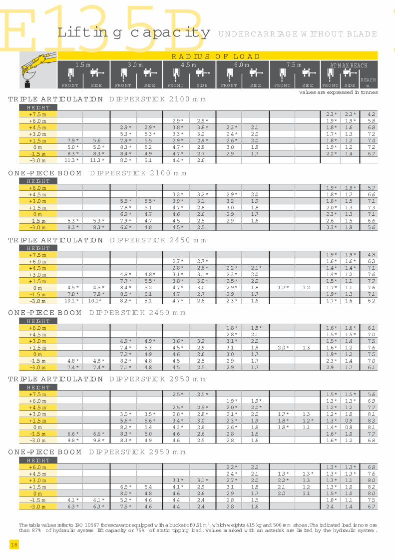
The table values refer to ISO 10567 for excavator equipped with a bucket of 0,61 m 3, which weights 415 kg and 500 m m shoes. The indicated load is no m orethan 87% of hydraulic system lift capacity or 75% of static tipping load. Values m arked with an asterisk are lim ited by the hydraulic system .
Values are expressed in tonnes
Liftin g c apacity
1.5 m
SIDE
AT M AX REACH
REACHmSIDEFRONT
3.0 m 4.5 m 6.0 m 7.5 m
SIDEFRONT SIDEFRONT SIDEFRONT SIDEFRONT FRONT
R A D IU S O F L O A D
+7.5 m+6.0 m+4.5 m+3.0 m+1.5 m0 m
-1.5 m-3.0 m
HEIGHT
TRIPLE ARTICULATIO N DIPPERSTICK 2100 m m
2.3* 2.3* 4.22.9* 2.9* 1.9* 1.9* 5.8
2.9* 2.9* 3.8* 3.8* 2.3* 2.1 1.8* 1.6 6.85.3* 5.3* 3.3* 3.2 2.4* 2.0 1.7* 1.3 7.2
7.9* 5.6 7.9* 5.5 2.9* 2.9* 2.6* 2.0 1.8* 1.2 7.45.0* 5.0* 8.3* 5.2 4.7* 2.8 3.0 1.8 1.9* 1.2 7.28.3* 8.3* 8.4* 4.9 4.7* 2.7 2.9 1.7 2.2* 1.4 6.711.3* 11.3* 8.0* 5.1 4.4* 2.6
+6.0 m+4.5 m+3.0 m+1.5 m0 m
-1.5 m-3.0 m
HEIGHTO NE-PIECE BO O M DIPPERSTICK 2100 m m
1.9* 1.9* 5.73.2* 3.2* 2.9* 2.0 1.8* 1.7 6.6
5.5* 5.5* 3.9* 3.1 3.2 1.9 1.8* 1.5 7.17.8* 5.1 4.7* 2.8 3.0 1.8 2.0* 1.3 7.36.9* 4.7 4.6 2.6 2.9 1.7 2.3* 1.3 7.1
5.3* 5.3* 7.9* 4.7 4.5 2.5 2.9 1.6 2.6 1.5 6.68.3* 8.3* 6.6* 4.8 4.5* 2.5 3.3* 1.9 5.6
+7.5 m+6.0 m+4.5 m+3.0 m+1.5 m0 m
-1.5 m-3.0 m
HEIGHTTRIPLE ARTICULATIO N DIPPERSTICK 2450 m m
1.9* 1.9* 4.82.7* 2.7* 1.6* 1.6* 6.32.8* 2.8* 2.2* 2.1* 1.4* 1.4* 7.1
4.8* 4.8* 3.1* 3.1* 2.3* 2.0 1.4* 1.2 7.67.7* 5.5* 3.8* 3.0* 2.5* 2.0 1.5* 1.1 7.7
4.5* 4.5* 8.4* 5.2 4.7* 3.0 2.9* 1.8 1.7* 1.2 1.7* 1.1 7.67.8* 7.8* 8.5* 5.1 4.7 2.7 2.9 1.7 1.9* 1.3 7.110.1* 10.1* 8.2* 5.1 4.7* 2.6 2.3* 1.6 1.7* 1.6 6.2
+6.0 m+4.5 m+3.0 m+1.5 m0 m
-1.5 m-3.0 m
HEIGHT
O NE-PIECE BO O M DIPPERSTICK 2450 m m
1.8* 1.8* 1.6* 1.6* 6.12.8* 2.1 1.5* 1.5* 7.0
4.9* 4.9* 3.6* 3.2 3.1* 2.0 1.5* 1.4 7.57.4* 5.3 4.5* 2.9 3.1 1.8 2.0* 1.3 1.6* 1.2 7.67.2* 4.9 4.6 2.6 3.0 1.7 1.9* 1.2 7.5
4.8* 4.8* 8.2* 4.8 4.5 2.5 2.9 1.7 2.3* 1.4 7.07.4* 7.4* 7.1* 4.8 4.5 2.5 2.9 1.7 2.9 1.7 6.1
+7.5 m+6.0 m+4.5 m+3.0 m+1.5 m0 m
-1.5 m-3.0 m
HEIGHT
TRIPLE ARTICULATIO N DIPPERSTICK 2950 m m
2.5* 2.5* 1.5* 1.5* 5.61.9* 1.9* 1.3* 1.3* 6.9
2.5* 2.5* 2.0* 2.0* 1.2* 1.2 7.73.5* 3.5* 2.8* 2.8* 2.1* 2.0 1.7* 1.3 1.2* 1.0 8.15.6* 5.6* 3.4* 3.0 2.3* 1.9 1.8* 1.2* 1.3* 0.9 8.38.2* 5.4 4.3* 2.8 2.6* 1.8 1.8* 1.1 1.4* 0.9 8.1
6.6* 6.6* 8.3* 5.0 4.6 2.6 2.8 1.6 1.6* 1.0 7.79.8* 9.8* 8.3* 4.9 4.6 2.5 2.8 1.6 1.6* 1.2 6.8
2.2* 2.2 1.3* 1.3* 6.82.4* 2.1 1.3* 1.3* 1.3* 1.3* 7.6
3.1* 3.1* 2.7* 2.0 2.2* 1.3 1.3* 1.1 8.06.5* 5.4 4.1* 2.9 3.1 1.8 2.1 1.2 1.3* 1.0 8.28.0* 4.8 4.6 2.6 2.9 1.7 2.0 1.1 1.5* 1.0 8.0
4.1* 4.1* 5.2* 4.6 4.4 2.4 2.8 1.5 1.8* 1.1 7.56.3* 6.3* 7.5* 4.6 4.4 2.4 2.8 1.6 2.4 1.4 6.7
+6.0 m+4.5 m+3.0 m+1.5 m0 m
-1.5 m-3.0 m
HEIGHT
O NE-PIECE BO O M DIPPERSTICK 2950 m m
UNDERCARRIAGE W ITHO UT BLADE

19
E135B
The table values refer to ISO 10567 for excavator equipped with a bucket of 0,61 m 3, which weights 415 kg and 500 m m shoes. The indicated load is no m orethan 87% of hydraulic system lift capacity or 75% of static tipping load. Values m arked with an asterisk are lim ited by the hydraulic system .
Values are expressed in tonnes
Liftin g c apacity
1.5 m
SIDE
AT M AX REACH
REACHmSIDEFRONT
3.0 m 4.5 m 6.0 m 7.5 m
SIDEFRONT SIDEFRONT SIDEFRONT SIDEFRONT FRONT
R A D IU S O F L O A D
+7.5 m+6.0 m+4.5 m+3.0 m+1.5 m0 m
-1.5 m-3.0 m
HEIGHT
TRIPLE ARTICULATIO N DIPPERSTICK 2100 m m
2.3* 2.3* 4.22.8* 2.8* 1.9* 1.9* 5.8
3.8* 3.8* 2.9* 2.9* 2.3* 2.2 1.7* 1.7 6.85.3* 5.3* 3.2* 3.2* 2.4* 2.1 1.7* 1.4 7.37.9* 5.9 4.0* 3.2 2.6* 2.1 1.7* 1.3 7.4
4.9* 4.9* 8.4* 5.6 4.9 3.0 3.0* 1.9 1.9* 1.3 7.28.2* 8.2* 8.5* 5.3 5.0 2.8 3.1 1.8 2.2* 1.5 6.711.2* 11.2* 8.0* 5.4 4.4* 2.8
+7.5 m+6.0 m+4.5 m+3.0 m+1.5 m0 m
-1.5 m-3.0 m
HEIGHTTRIPLE ARTICULATIO N DIPPERSTICK 2450 m m
1.9* 1.9* 4.82.7* 2.7* 1.6* 1.6* 6.32.8* 2.8* 2.2* 2.2* 1.5* 1.5* 7.1
4.8* 4.8* 3.1* 3.1* 2.3* 2.2 1.4* 1.3 7.67.7* 5.8 3.8* 3.2 2.5* 2.1 1.5* 1.2 7.7
4.5* 4.5* 8.4* 5.5 4.7* 3.1* 2.9* 2.0 1.7* 1.3 1.7* 1.2 7.67.8* 7.8* 8.5* 5.4 5.0 2.9 3.1 1.8 1.9* 1.4 7.110.1* 10.1* 8.2* 5.4 4.9* 2.8 2.3* 1.8 1.7* 1.7* 6.2
+6.0 m+4.5 m+3.0 m+1.5 m0 m
-1.5 m-3.0 m
HEIGHT
O NE-PIECE BO O M DIPPERSTICK 2450 m m
1.8* 1.8* 1.6* 1.6* 6.12.8* 2.3 1.5* 1.5* 7.0
4.9* 4.9* 3.6* 3.4 3.1* 2.1 1.5* 1.5 7.57.4* 5.6 4.5* 3.1 3.3 2.0 2.0* 1.4 1.6* 1.3 7.67.2* 5.2 5.0 2.8 3.2 1.9 1.9* 1.3 7.5
4.8* 4.8* 8.2* 5.1 4.8 2.7 3.1 1.8 2.3* 1.5 7.07.4* 7.4* 7.1* 5.2 4.8* 2.7 3.1 1.8 3.1* 1.8 6.1
+7.5 m+6.0 m+4.5 m+3.0 m+1.5 m0 m
-1.5 m-3.0 m
HEIGHT
TRIPLE ARTICULATIO N DIPPERSTICK 2950 m m
2.5* 2.5* 1.6* 1.6* 5.61.9* 1.9* 1.3* 1.3* 6.9
2.5* 2.5* 2.0* 2.0* 1.2* 1.2* 7.73.5* 3.5* 2.8* 2.8* 2.1* 2.1* 1.7* 1.4 1.2* 1.1 8.15.6* 5.6* 3.4* 3.2 2.3* 2.0* 1.8* 1.3 1.3* 1.0 8.38.2* 5.7 4.3* 3.0 2.6* 1.9 1.8* 1.2 1.4* 1.0 8.1
6.6* 6.6* 8.3* 5.3 4.8 2.8 2.9* 1.7 1.6* 1.1 7.79.8* 9.8* 8.3* 5.2 4.9 2.7 3.0 1.7 1.6* 1.4 6.8
2.2* 2.2* 1.3* 1.3* 6.82.4* 2.3 1.3* 1.3* 1.3* 1.3* 7.6
3.1* 3.1* 2.7* 2.1 2.2* 1.4 1.3* 1.2 8.06.5* 5.8 4.1* 3.1 3.2* 1.9 2.3 1.3 1.3* 1.1 8.27.7* 5.1 4.9* 2.8 3.1 1.8 2.2 1.2 1.5* 1.1 8.0
4.1* 4.1* 8.2* 4.9 4.7 2.6 3.0 1.7 1.8* 1.2 7.56.3* 6.3* 7.5* 4.9 4.7 2.6 3.0 1.7 2.5 1.5 6.7
+6.0 m+4.5 m+3.0 m+1.5 m0 m
-1.5 m-3.0 m
HEIGHT
O NE-PIECE BO O M DIPPERSTICK 2950 m m
+6.0 m+4.5 m+3.0 m+1.5 m0 m
-1.5 m-3.0 m
HEIGHTO NE-PIECE BO O M DIPPERSTICK 2100 m m
1.9* 1.9* 5.73.2* 3.2* 2.9* 2.2 1.8* 1.8* 6.7
5.5* 5.5* 3.9* 3.3 3.2* 2.1 1.8* 1.6 7.27.8* 5.4 4.7* 3.0 3.3 1.9 2.0* 1.4 7.37.0* 5.1 4.9 2.8 3.1 1.8 2.3* 1.4 7.1
5.3* 5.3* 7.9* 5.0 4.8 2.7 3.1 1.8 2.7 1.6 6.68.4* 8.4* 6.6* 5.2 4.5* 2.7 3.4* 2.0 5.6
UND ERCARRIAGE W ITH BLADE