Embed Size (px)
Citation preview

Cat. No. E30E-EN-01A Note: Specifications subject to change without notice.
E3NT-L
Diffuse R
eflective Sensor O
PERATIO
N M
AN
UA
LC
at. No. E30E-EN
-01A
OPERATION MANUAL
Photoelectric Sensor
Diffuse Reflective Sensor E3NT-L
Authorised Distributor:
Printed in Europe
dummy.qxd 26.09.2005 13:38 Seite 1
Cat. No. E30E-EN-01A

TABLE OF CONTENTS
SECTION 1 Important Precautions . . . . . . . . . . . . . . . . . . . . . . . . . . . 51-1 Using the operating instructions . . . . . . . . . . . . . . . . . . . . . . . . . . . . . . . . . . . . . . . 6
1-2 Use in accordance with the intended purpose . . . . . . . . . . . . . . . . . . . . . . . . . . . . . 6
1-3 Use that is not in accordance with the intended purpose . . . . . . . . . . . . . . . . . . . . 6
1-4 Electromagnetic compatibility (EMC) . . . . . . . . . . . . . . . . . . . . . . . . . . . . . . . . . . 6
1-5 Warranty and liability . . . . . . . . . . . . . . . . . . . . . . . . . . . . . . . . . . . . . . . . . . . . . . . 7
1-6 Key to symbols . . . . . . . . . . . . . . . . . . . . . . . . . . . . . . . . . . . . . . . . . . . . . . . . . . . . 7
1-7 Abbreviations . . . . . . . . . . . . . . . . . . . . . . . . . . . . . . . . . . . . . . . . . . . . . . . . . . . . . 7
SECTION 2 Safety Notes . . . . . . . . . . . . . . . . . . . . . . . . . . . . . . . . . . . . 9
2-1 Safety notes . . . . . . . . . . . . . . . . . . . . . . . . . . . . . . . . . . . . . . . . . . . . . . . . . . . . . . . 10
SECTION 3 Specification. . . . . . . . . . . . . . . . . . . . . . . . . . . . . . . . . . . . 11
3-1 Diffuse reflective sensor . . . . . . . . . . . . . . . . . . . . . . . . . . . . . . . . . . . . . . . . . . . . . 12
3-2 Optical data link E3NT-AL232 (order separately) . . . . . . . . . . . . . . . . . . . . . . . . . 17
3-3 Dimensions . . . . . . . . . . . . . . . . . . . . . . . . . . . . . . . . . . . . . . . . . . . . . . . . . . . . . . . 18
SECTION 4 Function . . . . . . . . . . . . . . . . . . . . . . . . . . . . . . . . . . . . . . . 23
4-1 Functions . . . . . . . . . . . . . . . . . . . . . . . . . . . . . . . . . . . . . . . . . . . . . . . . . . . . . . . . . 24
4-2 Display and operator controls . . . . . . . . . . . . . . . . . . . . . . . . . . . . . . . . . . . . . . . . . 26
4-3 User set parameters . . . . . . . . . . . . . . . . . . . . . . . . . . . . . . . . . . . . . . . . . . . . . . . . . 27
4-4 Inputs/Outputs . . . . . . . . . . . . . . . . . . . . . . . . . . . . . . . . . . . . . . . . . . . . . . . . . . . . . 33
SECTION 5 Transport . . . . . . . . . . . . . . . . . . . . . . . . . . . . . . . . . . . . . . 35
5-1 Packaging / Transportation damage . . . . . . . . . . . . . . . . . . . . . . . . . . . . . . . . . . . . 36
5-2 Storage . . . . . . . . . . . . . . . . . . . . . . . . . . . . . . . . . . . . . . . . . . . . . . . . . . . . . . . . . . 36
5-3 Scope of delivery. . . . . . . . . . . . . . . . . . . . . . . . . . . . . . . . . . . . . . . . . . . . . . . . . . . 36
SECTION 6 Assembly . . . . . . . . . . . . . . . . . . . . . . . . . . . . . . . . . . . . . . 37
6-1 Safety notes . . . . . . . . . . . . . . . . . . . . . . . . . . . . . . . . . . . . . . . . . . . . . . . . . . . . . . . 38
6-2 Sensor assembly . . . . . . . . . . . . . . . . . . . . . . . . . . . . . . . . . . . . . . . . . . . . . . . . . . . 38
3

TABLE OF CONTENTS
SECTION 7 Electrical Connection . . . . . . . . . . . . . . . . . . . . . . . . . . . . 417-1 Safety notes . . . . . . . . . . . . . . . . . . . . . . . . . . . . . . . . . . . . . . . . . . . . . . . . . . . . . . 42
7-2 Establishing electrical connection . . . . . . . . . . . . . . . . . . . . . . . . . . . . . . . . . . . . . 42
7-3 Connection diagrams . . . . . . . . . . . . . . . . . . . . . . . . . . . . . . . . . . . . . . . . . . . . . . . 43
7-4 Connection in line with EMC requirements . . . . . . . . . . . . . . . . . . . . . . . . . . . . . 45
SECTION 8 Setting into Operation. . . . . . . . . . . . . . . . . . . . . . . . . . . . 47
8-1 Safety notes . . . . . . . . . . . . . . . . . . . . . . . . . . . . . . . . . . . . . . . . . . . . . . . . . . . . . . 48
8-2 Switching on the operating voltage . . . . . . . . . . . . . . . . . . . . . . . . . . . . . . . . . . . . 48
8-3 Aligning the sensor . . . . . . . . . . . . . . . . . . . . . . . . . . . . . . . . . . . . . . . . . . . . . . . . 49
8-4 Setting the switching points. . . . . . . . . . . . . . . . . . . . . . . . . . . . . . . . . . . . . . . . . . 50
SECTION 9 Sensor Set-up . . . . . . . . . . . . . . . . . . . . . . . . . . . . . . . . . . . 51
9-1 Setting the sensor using the push buttons . . . . . . . . . . . . . . . . . . . . . . . . . . . . . . . 52
9-2 Setting the sensor with a PC . . . . . . . . . . . . . . . . . . . . . . . . . . . . . . . . . . . . . . . . . 60
SECTION 10 Maintenance and Repair. . . . . . . . . . . . . . . . . . . . . . . . . . 61
10-1 Maintenance. . . . . . . . . . . . . . . . . . . . . . . . . . . . . . . . . . . . . . . . . . . . . . . . . . . . . . 62
10-2 Repair. . . . . . . . . . . . . . . . . . . . . . . . . . . . . . . . . . . . . . . . . . . . . . . . . . . . . . . . . . . 62
SECTION 11 Accessories and Parts . . . . . . . . . . . . . . . . . . . . . . . . . . . . 63
11-1 Accessories and parts. . . . . . . . . . . . . . . . . . . . . . . . . . . . . . . . . . . . . . . . . . . . . . . 64
SECTION 12 Appendix . . . . . . . . . . . . . . . . . . . . . . . . . . . . . . . . . . . . . . 65
12-1 Error messages. . . . . . . . . . . . . . . . . . . . . . . . . . . . . . . . . . . . . . . . . . . . . . . . . . . . 66
12-2 Factory default settings . . . . . . . . . . . . . . . . . . . . . . . . . . . . . . . . . . . . . . . . . . . . . 67
4

SECTION 1Important Precautions
1-1 Using the operating instructions . . . . . . . . . . . . . . . . . . . . . . . . . . . . . . . . . . . 61-2 Use in accordance with the intended purpose . . . . . . . . . . . . . . . . . . . . . . . . . 61-3 Use that is not in accordance with the intended purpose . . . . . . . . . . . . . . . . 61-4 Electromagnetic compatibility (EMC) . . . . . . . . . . . . . . . . . . . . . . . . . . . . . . 61-5 Warranty and liability . . . . . . . . . . . . . . . . . . . . . . . . . . . . . . . . . . . . . . . . . . . 71-6 Key to symbols . . . . . . . . . . . . . . . . . . . . . . . . . . . . . . . . . . . . . . . . . . . . . . . . 71-7 Abbreviations . . . . . . . . . . . . . . . . . . . . . . . . . . . . . . . . . . . . . . . . . . . . . . . . . 7
5

Using the operating instructions Section 1-1
1-1 Using the operating instructionsThese operating instructions refer exclusively to diffuse reflective sensors inthe E3NT type series. They contain the most important notes for operating thesensor in line with safety requirements. The operating instructions must always be close at hand and accessible at alltimes, and must be kept together with the higher-level machine installation. The contents of these operating instructions must be read and understood,and all its points must be followed by everyone who is responsible for machineplanning, assembly and operation. This particularly applies to the safetynotes.Observance of the safety notes will help to avoid accidents, malfunctions andfaults.
1-2 Use in accordance with the intended purposeDiffuse reflective sensors in the E3NT type series are always operated as partof a higher-level overall system, e.g. a machine installation.They may only be used as optical sensors to check the presence of objectswithin a machine installation with a higher-level control system.Any other use, or any use exceeding this scope, is not permitted. Use in accordance with the intended purpose also includes observance of theoperating instructions and keeping to the inspection and maintenance specifi-cations in accordance with the system documentation.
1-3 Use that is not in accordance with the intended purposeDiffuse reflective sensors in the E3NT type series must not be used as safetycomponents within the scope of the EU machine guideline.Its use in applications in which the safety of persons depends on functioningof the sensor is not permissible!
1-4 Electromagnetic compatibility (EMC)Diffuse reflective sensors in the E3NT type series are built to conform to thefollowing standards:
• EN 60947-5-2 Low-voltage switch gear - Part 5-2:Control devices and switching elements: proximity switches
• EN 50081-2/-1Basic interference emission standardIndustrial area/small establishments
• EN 61000-6-2 Basic interference immunity standardIndustrial area
6

Warranty and liability Section 1-5
1-5 Warranty and liabilityOur Terms and Conditions of Delivery and Payment fundamentally apply. These are available to the owner at the latest as from conclusion of a contract.Warranty and liability claims for personal injury and property damage areruled out if they are attributable to one or several of the following causes:
• Use of the sensor that is not in accordance with its intended purpose
• Improper assembly, commissioning and maintenance of the sensor
• Failure to observe the notes in the operating instructions in relation totransport, storage, assembly, commissioning and maintenance of thesensor
• Unauthorised structural changes to the sensor
• Repairs carried out improperly
• Disasters resulting from the influence of foreign bodies and acts of God.
1-6 Key to symbolsThe following symbols are used in these operating instructions:
Important information
Risk of damage to the machine or material
Risk of injury to life and limb in general
1-7 AbbreviationsThe following abbreviations are used in these operating instructions:
• BGS BackGround Suppression• FGS ForeGround Suppression• IR InfraRed• PC Personal Computer
7

Abbreviations Section 1-7
8

SECTION 2Safety Notes
2-1 Safety notes . . . . . . . . . . . . . . . . . . . . . . . . . . . . . . . . . . . . . . . . . . . . . . . . . . . 10
9

Safety notes Section 2-1
2-1 Safety notesThe diffuse reflective sensors belonging to the E3NT type series mayonly be used as described in these operating instructions. They may only be operated as part of a higher-level overall system,e.g. a machine installation.
During machine planning and the use of diffuse reflective sensorsbelonging to the E3NT type series, the safety and accident preventionregulations that are specific to use must be observed, e.g.:•EN 292, Safety of machines, general design principles•EN 60204, Electrical equipment of machines
Diffuse reflective sensors belonging to the E3NT type series must notbe used as safety components within the scope of the EU Machineguidelines.Their use in applications in which the safety of persons depends onfunctioning of the sensor is not permissible!
The manufacturer and owner of the higher-level overall system, e.g. ofa machine installation, is responsible for conformity with the nationaland international safety and accident prevention regulations that applyto the special application.
Assembly, electrical connection and maintenance may only be carriedout by instructed, trained and authorised specialist personnel inaccordance with applicable regulations after de-energising the powersupply and switching off the machine.The machine must be safeguarded against reactivation.
Conversions and changes as well as tampering with the interior of thesensor, the data link and the alignment tool are forbidden.The notes contained in these operating instructions, in particular thechapters entitled Safety notes and Maintenance and repair, must beintegrated into the operating instructions of the higher-level overall sys-tem.
10

SECTION 3Specification
3-1 Diffuse reflective sensor . . . . . . . . . . . . . . . . . . . . . . . . . . . . . . . . . . . . . . . . . 123-1-1 General data . . . . . . . . . . . . . . . . . . . . . . . . . . . . . . . . . . . . . . . . . . . 123-1-2 Optical data. . . . . . . . . . . . . . . . . . . . . . . . . . . . . . . . . . . . . . . . . . . . 123-1-3 Mechanical data . . . . . . . . . . . . . . . . . . . . . . . . . . . . . . . . . . . . . . . . 133-1-4 Electrical data . . . . . . . . . . . . . . . . . . . . . . . . . . . . . . . . . . . . . . . . . . 143-1-5 Standards and approvals . . . . . . . . . . . . . . . . . . . . . . . . . . . . . . . . . . 153-1-6 Parallel operating range . . . . . . . . . . . . . . . . . . . . . . . . . . . . . . . . . . 163-1-7 Black/White-error (6 % / 90 % remission, typical) . . . . . . . . . . . . . 163-1-8 Hysteresis (typical) . . . . . . . . . . . . . . . . . . . . . . . . . . . . . . . . . . . . . . 16
3-2 Optical data link E3NT-AL232 (order separately) . . . . . . . . . . . . . . . . . . . . . 173-3 Dimensions . . . . . . . . . . . . . . . . . . . . . . . . . . . . . . . . . . . . . . . . . . . . . . . . . . . 18
3-3-1 Sensor E3NT-L17 with horizontal connector . . . . . . . . . . . . . . . . . . 183-3-2 Sensor E3NT-L37 with vertical connector . . . . . . . . . . . . . . . . . . . . 193-3-3 Universal mounting bracket E39-EL1 (order separately). . . . . . . . . 203-3-4 Adapter bracket E39-EL2 (order separately) . . . . . . . . . . . . . . . . . . 203-3-5 Optical data link E3NT-AL232 2m (order separately) . . . . . . . . . . . 21
11

Diffuse reflective sensor Section 3-1
3-1 Diffuse reflective sensor3-1-1 General data
3-1-2 Optical data
Sensor type E3NT-L@@7 Diffuse reflective sensor with background respectively fore-ground suppression
Signal evaluation Double triangulation method
Options Window heating, analog output
User settings By push button on the sensor or with a PC connected via the optical data link (order separately)
Operating modes Background suppression, foreground suppression, back-ground and foreground suppression (2-point window evalua-tion)
Optical data link (order separately) Set-up via a PC, real-time analog value output, firmware update
Emitted light Infrared, 850 - 880 nm
Rated sensing distance 2 m
Setting distance, Sr teachable/manual set-up0.2 ... 2.0 m (90 % remission)0.2 ...1.7 m (6% remission)
Standard measured object Kodak grey card 90%, 200 x 200 mm
Blind zone < 0.1 m
Black/white error (6%/90%) < 15 % (of setting distance Sr)
Hysteresis < 5 % of setting distance Sr (remission 90 %) or max. 4 cm< 10 % of setting distance Sr (remission 6 %) or max. 6 cm(higher value valid)
Repetition accuracy < 5 % (of setting distance Sr) or 4 cm (higher value valid)
Light spot diameter < 40 mm in the case of Sr = 2 m
Minimum object size > 40 mm
Ambient light immunity to EN 60947-5-2Halogen lamps (100-120 Hz)Fluorescent lamps (30 kHz)Energy saving lamps
> 10,000 lux> 5,000 lux> 2,000 lux(max. illuminance of an energy saving lamp)
12

Diffuse reflective sensor Section 3-1
3-1-3 Mechanical dataDimensions (length x width x depth) 85 x 27 x 65 mm
MaterialsHousing
Front paneKeyboardSeals
Powder-coated aluminium, sea-water resistant, 231 GD AlSi12 (Cu) (standard version)Aluminium with foodstuff-approved coating (option) GlassHTV siliconeRTV silicone
Housing colour Grey, RAL 7030
Assembly Screw fastening by way of four M5 threads and two M5 through holes or with universal mounting bracket (order sepa-rately)
Connection M12 connector, 5-pole (piercing)
Ambient temperature range - 40 °C ... + 55 °C (with window heating)- 25 °C ... + 55 °C- 10 °C ... + 55 °C (analog output)
Storage temperature range - 40 °C ... + 60 °C
Permissible relative humidity 35 % ... 95 %, no condensation
Front pane heating optional
Degree of protection to EN 60529/IEC 529 IP 67
Protection class II (50 V DC)
Resistance toVibration (to IEC 68-2-6)Shock (to IEC 68-2-27)
± 1.5 mm, 1 h , 10 - 70 Hz300 m/s²
13

Diffuse reflective sensor Section 3-1
3-1-4 Electrical dataUtilisation category to EN 60947-5-2 DC 12
Rated operating voltage + 24 V DC, polarised
Operating voltage range + 10 ... + 30 V DC
Current consumption < 90 mA with the display off< 110 mA with the display on
Power-on delay < 300 ms
Inputs/outputs Pin 2 = input (In 2) or output (Out 2)depending on set-up
Pin 4 = output (Out 1)
Pin 5 = Input (In 1) or analog outputdepending on model
Outputs User set functions(e.g. switching output, alarm output, ...)
Output circuit User set PNP (open collector), NPN (open collector) or com-plementary (push-pull)
Output current max. 100 mA
Voltage drop < 2.0 V
Residual current < 100 µA
Circuit protection Reversed power supply, overload and short-circuit (pulsed), mutual interferences
Inputs User set functions(e.g. teach-in, trigger, test, ...)
Input circuit Voltage input +10 V ... USupply
Pulse duration min. 1 ms
Analog output Current output 0 ... 21 mA- 3 mA correspond to distance < 0.2 m- 4 ... 20 mA correspond to distance 0.2 m ... 2.0 m- 21 mA correspond to distance > 2.0 m (or no object)
Switch-on/off time (TON / TOFF) ≤≤≤≤ 2.5 ms
Insulation resistance 20 MΩΩΩΩ at 500 V DC
Insulation voltage strength 1 kV AC, 50/60 Hz (1 min)
Impulse strength (insulation) 6 kV
14

Diffuse reflective sensor Section 3-1
3-1-5 Standards and approvals
* Function criterion ANormal functioning also ensured during a disturbance.
* Function criterion BNormal functioning ensured after a disturbance.
Interference withstand
General EN 60947-5-2 Proximity switchesEN 61000-6-2 Generic interference immunity standard, industrial area
Static discharge (ESD) EN 61000-4-2Contact ± 4 kV / air ± 8 kVFunction criterion A*
High-frequency electromagnetic fields (HF) EN 61000-4-380 ... 1000 MHz, 10 V/m, 80 %Function criterion A*
Fast transient interference quantities (burst) EN 61000-4-4± 2 kV, t/th = 5/50 (ns)Function criterion A*
Impulse voltages (surge) EN 61000-4-5± 1 kV, t/th = 1.2/50 (ns)Function criterion B*
Conducted disturbances EN 61000-4-63 V, 0.15 ... 80 MHz, 80 %Function criterion A*
Interference emission
General EN 60947-5-2 Proximity switchesEN 50081-2 Generic interference emission standard, industrial areaEN 50081-1 Generic interference emission standard, small establishments
Radio interference field strength EN 55011, 30 ... 1000 MHz
Radiated radio interference power EN 55011, 1 GHz ... 18 GHz
Permits UL (pending), CSA (pending)
15

Diffuse reflective sensor Section 3-1
3-1-6 Parallel operating range
3-1-7 Black/White-error (6 % / 90 % remission, typical)
3-1-8 Hysteresis (typical)
-30
-20
-10
0
10
20
30
0 500 1000 1500 2000 2500
Obj
ect p
ositi
on X
(mm
)
Distance Z (mm)
E3NT
XZ
Obj
ect
-10
-5
0
5
10
15
20
0 500 1000 1500 2000 2500
Bla
ck/W
hite
-err
or (%
)
Distance Z (mm)
E3NT
XZ
Obj
ect
0
5
10
15
0 500 1000 1500 2000 2500
Hys
tere
sis
(%)
Distance Z (mm)
E3NT
XZ
Obj
ect
black object
white object
16

Optical data link E3NT-AL232 (order separately) Section 3-2
3-2 Optical data link E3NT-AL232 (order separately)Dimensions (length x width x depth) 29.5 x 72.9 x 26.4 mm
Housing material ABS and PMMA (IR transparent)
Housing colour Black, RAL 9005
Assembly Snap mounting on sensor
Connection 2 m connecting cable with 9-pole sub-D connector
Ambient temperature range - 10 °C ... + 50 °C
Storage temperature range - 40 °C ... + 60 °C
Permissible relative humidity 35 % ... 85 %, no condensation
Degree of protection to EN 60529 / IEC 529 IP 54
Emitted light IR communication element 880 nm
Rated operating voltage Via RS232 interface from PC
Current consumption 6 mA
17

Dimensions Section 3-3
3-3 Dimensions3-3-1 Sensor E3NT-L17 with horizontal connector
14 33.4
1427
M12
14.3
88.7
30 23.1 15.7
4.7
65.1
M5 (2x)
M5 (4x)
receiver 1
emitter
receiver 2
18

Dimensions Section 3-3
3-3-2 Sensor E3NT-L37 with vertical connector
12.1
23.130
65.1
15.2
4.7
M12
14 33.4
142788
.7
M5 (2x)
M5 (4x)
receiver 1
emitter
receiver 2
19

Dimensions Section 3-3
3-3-3 Universal mounting bracket E39-EL1 (order separately)
3-3-4 Adapter bracket E39-EL2 (order separately)
ø 4.2 ±0.1
15
R30
74
10°
7
R25
10.5
9.5°
28
R82.74
10°
55.5
92
4 90°
ø4.
2±0
.1
Rx
6012
0±1
38±1
R30
30°
84.5
26
25°
R80
.62
10
7
7
ø 5.3±0.1
14
2.5
46
50°
11
Rx 25
17.5
28°
8.5
30
R22
.5
R 28.4
15°
39.5
31
108
Rx 7
5
95
ø6.3±0.1
30
45
43.4
20
22.5
15
7 ø5.2
10
20.3
2
ø 6.3
7.8
R 3
90°Rx
20

Dimensions Section 3-3
3-3-5 Optical data link E3NT-AL232 2m (order separately)
cable 2 m
68,9
2730
21

Dimensions Section 3-3
22

SECTION 4Function
4-1 Functions . . . . . . . . . . . . . . . . . . . . . . . . . . . . . . . . . . . . . . . . . . . . . . . . . . . . . 244-2 Display and operator controls . . . . . . . . . . . . . . . . . . . . . . . . . . . . . . . . . . . . . 26
4-2-1 LED display . . . . . . . . . . . . . . . . . . . . . . . . . . . . . . . . . . . . . . . . . . . 264-2-2 LEDs . . . . . . . . . . . . . . . . . . . . . . . . . . . . . . . . . . . . . . . . . . . . . . . . . 264-2-3 Push buttons on the sensor . . . . . . . . . . . . . . . . . . . . . . . . . . . . . . . . 274-2-4 Set-up via a PC . . . . . . . . . . . . . . . . . . . . . . . . . . . . . . . . . . . . . . . . . 27
4-3 User set parameters . . . . . . . . . . . . . . . . . . . . . . . . . . . . . . . . . . . . . . . . . . . . . 274-3-1 Mode . . . . . . . . . . . . . . . . . . . . . . . . . . . . . . . . . . . . . . . . . . . . . . . . . 284-3-2 Output function. . . . . . . . . . . . . . . . . . . . . . . . . . . . . . . . . . . . . . . . . 294-3-3 Switching points . . . . . . . . . . . . . . . . . . . . . . . . . . . . . . . . . . . . . . . . 294-3-4 Output switching. . . . . . . . . . . . . . . . . . . . . . . . . . . . . . . . . . . . . . . . 294-3-5 Function of connector pin 2 . . . . . . . . . . . . . . . . . . . . . . . . . . . . . . . 304-3-6 Switch-on delay . . . . . . . . . . . . . . . . . . . . . . . . . . . . . . . . . . . . . . . . 304-3-7 Switch-off response . . . . . . . . . . . . . . . . . . . . . . . . . . . . . . . . . . . . . 304-3-8 Timing diagrams . . . . . . . . . . . . . . . . . . . . . . . . . . . . . . . . . . . . . . . . 314-3-9 Type of display . . . . . . . . . . . . . . . . . . . . . . . . . . . . . . . . . . . . . . . . . 324-3-10 Keyboard lock. . . . . . . . . . . . . . . . . . . . . . . . . . . . . . . . . . . . . . . . . . 324-3-11 ECO energy saving mode . . . . . . . . . . . . . . . . . . . . . . . . . . . . . . . . . 324-3-12 Direction of the display . . . . . . . . . . . . . . . . . . . . . . . . . . . . . . . . . . 324-3-13 Reset . . . . . . . . . . . . . . . . . . . . . . . . . . . . . . . . . . . . . . . . . . . . . . . . . 32
4-4 Inputs/Outputs . . . . . . . . . . . . . . . . . . . . . . . . . . . . . . . . . . . . . . . . . . . . . . . . . 334-4-1 Inputs . . . . . . . . . . . . . . . . . . . . . . . . . . . . . . . . . . . . . . . . . . . . . . . . 334-4-2 Outputs . . . . . . . . . . . . . . . . . . . . . . . . . . . . . . . . . . . . . . . . . . . . . . . 34
23

Functions Section 4-1
4-1 FunctionsDiffuse reflective sensors in the E3NT type series can be operated with back-ground and foreground suppression. Genuine window evaluation can also beset. The distance is evaluated in accordance with the double triangulationprinciple. In this case, the distance from the measured object is determinednot only via the intensity of the reflected emitted light, but also via the anglebetween the emitter, the measured object and the receiver.
Contrary to sensors with single triangulation, E3NT with double trian-gulation, allows measured object's direction of motion to be in all threedirections. Thus, the rotatory position of the sensor about its opticalaxis can be chosen freely (see Figure 1 Position of the sensor).
Figure 1 Position of the sensor
If the light spot is not completely on the same plane target object (min-imum object size) the distance is not determined and malfunction canoccur (see Figure 2 Not determined distance). If necessary a triggersignal or timer function has to be applied.
Figure 2 Not determined distance
Measured objects are detected only within the user set and strictly limitedsensing zone. Objects outside the sensing zone (depending on the settings, inthe background, in the foreground or outside of a window that is defined bytwo user set distance points) are ignored.
24

Functions Section 4-1
Due to the infrared emitted light and the very low minimum reflection factor of6 %, objects can be detected largely independently of their colour and theirsurface finish. The sensor can be user set by push button on the unit or with a
PC and the SensorSupportSoftware S3 (order separately) via an opticaldata interface E3NT-AL232 (order separately). The optical data interfaceoperates with an IR communication element. Through the optical data inter-face, the analog distance data can also be transferred continously to a PC/laptop and stored there.
25

Display and operator controls Section 4-2
4-2 Display and operator controlsOperating states are displayed by a 4-digit 7-segment LED display and twoLEDs.The sensor can be operated/set either by push buttons on the sensor or with aPC and setting software (order separately) via an optical data interface (orderseparately).
Figure 3 Operator controls and displays
4-2-1 LED displayThe distance from the measured object and the names of the menu levelsduring set-up of the sensor are displayed by the 4-digit 7-segment LED dis-play. The display appears as red digits or letters. If the sensor is set to a bar chart display, the distance from the measuredobject is displayed as a green LED bar chart.
4-2-2 LEDsThe switching status and the stability of the two outputs are signalled as fol-lows by two LEDs, visible from the top and the front of the sensor:
• Yellow LED ON: Object stably detected(Output 1) Blinking: Object not stably detected
OFF: No object within range
• Red LED ON: Object stably detected(Output 2) Blinking: Object not stably detected
OFF: No object within range
The status LED is only visible from the top of the sensor:
• Status LED ON: Set-up menu selectedBlinking: Menu level with change of setting distanceOFF: RUN (normal) mode
optical IR element for data communication
Red LED(Output 2)Yellow LED(Output 1)
Alignment aid
Status LEDLED display
Decrement Increment ENTER
26

User set parameters Section 4-3
4-2-3 Push buttons on the sensorOn the sensor, there are three push buttons for the setting of the sensor (seeFigure 3 Operator controls and displays):
• Minus key • Plus key • Enter key
With these three push buttons, the operator moves through the sensor's menuand sets the parameters in accordance with the application. Therefore, themost frequently used parameters can be set directly on the sensor.
4-2-4 Set-up via a PCAll parameters of the sensor can be set with a PC and the OMRON Sensor-SupportSoftware S3. The connection between the sensor and the PC isestablished via an optical data interface. The data interface is connected to afree COM port of a PC/laptop. Refer to the separate operating instructions ABBO 0018 for further informa-
tion on setting with a PC and the SensorSupportSoftware S3.
4-3 User set parametersThe following parameters can be user set either by push buttons on the sen-sor or with a PC and the set-up software (order separately) via the optical datainterface (order separately):
• Mode• Output function• Teach/set switching points• Output switching • Function on connector pins 2 and 5• Switch-on and off delay• Type of switch-off time function• Type of display on the sensor• Keyboard lock• Energy saving mode• Display direction• Reset to factory defaults
The following functions can only be set with a PC and the set-up software(order separately) via the optical data interface (order separately):
• Complete sensor locking
27

User set parameters Section 4-3
4-3-1 ModeThe diffuse reflective sensor can be operated in the following modes:
• Background suppression BGS (factory default)Measured objects are detected as from the blind zone up to the user setor teached switching point SA. Objects in the background, behind the userset switching point, are ignored.
Figure 4 Background suppression
Accordingly for output 2 the switching point C (SC) is set.
• Foreground suppression FGSMeasured objects are detected as from the user set switching point SA upto the maximum sensing distance. Objects in the foreground, between thesensor’s blind zone and the user set switching point, are ignored.
Figure 5 Foreground suppression
Accordingly for output 2 the switching point C (SC) is set.
SSA
0
1A
Output 1
SSA
0
1A
Output 1
28

User set parameters Section 4-3
• Window evaluation Measured objects are detected only in the measurement window betweenthe two user set switching points (switching zone). Objects outside of thismeasurement window in the foreground and in the background areignored.Window evaluation involves logical AND combination of the FGS andBGS modes.
Figure 6 Window evaluation
Accordingly for output 2 the switching points C and D are set.
4-3-2 Output functionThe output function can be set separately for both outputs:
• Light on (factory default)The output is active when a measured object is detected.
• Dark onThe output is active when no measured object is detected.
4-3-3 Switching points
The switching points can be set on a positioned measured object or can beuser set by input of switching points.In the window evaluation mode, two switching points must be defined foreach output.In the FGS or BGS mode, only one switching point needs to be defined foreach output.
4-3-4 Output switchingOutput switching can be user set jointly for both outputs:
• PNP, plus-switching, open collector (factory default)• NPN, minus-switching, open collector• Push-pull, complementary, plus/minus-switching
See SECTION 7-3 Connection diagrams.
SSA
0
1A
SB
B
Output 1
29

User set parameters Section 4-3
4-3-5 Function of connector pin 2Pin 2 of the connector can be user set as Output 2 (OUT 2), as an alarm out-put, as a teaching input for switching points A and B, as a test input or as atrigger input.
4-3-6 Switch-on delayThis defines the switch-on response (light-on mode). The time is adjustablebetween 0 ms and 9999 ms.
• Switch-on delayThe switch-on delay starts as from the time when the measured objectenters the sensing zone. The output does not become active until theswitch-on delay has elapsed.
4-3-7 Switch-off responseThis defines the switch-off response (light-on mode). The time is adjustablebetween 0 ms and 9999 ms.
• Switch-off delayThe switch-off delay starts as from the time when the measured objectleaves the sensing zone. The output does not become inactive until theswitch-off delay has elapsed.
• Minimum pulse widthAfter detection of a measured object, the output remains active for at leastthe user set switch-off delay. If the measured object dwells in the sensingzone for longer than the set switch-off delay, the output becomes inactiveimmediately after the object leaves the sensing zone.
• Constant pulse widthAfter detection of a measured object, the output only remains active dur-ing the user set switch-off delay and becomes inactive after this time haselapsed, regardless of the measured object's dwell time, even if themeasured object stays in the sensing zone for longer than the user setswitch-off delay.
30
31
User set param
etersS
ection
4-3
4-3-8T
imin
g d
iagram
s
Td2
Td2
Td3 Td3
Td3 Td3Td3
Td1
Td1Td1
Td1
Td1
Td1
Td2
Td2
Td2detected
not detected
ON
OFF
detected
not detected
ON
OFF
ON
OFF
detected
not detected
ON
OFF
ON
OFF
on-delay: Td1 off-delay: Td2 min/const.: Td3note:
object
Mode on-1 (on-/off-delay)
object
only on-delay
only off-delay
on - and off-delay
Mode on-2 (minimum pulse width)
object
Mode on-3 (constant pulse width)
Timer functions off
Td3 Td3 Td3 Td3 Td3
Td3 Td3 Td3 Td3
Td1
Td1Td1 Td1 Td1
Td1Td1
Td1Td1
Td2 Td2 Td2
Td2 Td2 Td2
Td2

User set parameters Section 4-3
4-3-9 Type of displayThe measured distance can be displayed on the sensor's display in two differ-ent ways:
• AbsoluteThe absolute distance between the sensor and the measured object isdisplayed with red digits in m.
• BarThe distance between the sensor and the measured object is displayedas a green bar chart.
4-3-10 Keyboard lockWith the keyboard lock function, the push buttons on the sensor can be lockedto prevent inadvertent modification of the settings.The lock can be activated and deactivated on the sensor.When the keyboard lock is active, changes can only be made if the Minus and Plus keys have been pressed simultaneously for 4 seconds. This tem-porarily suppresses keyboard locking. If no key is pressed for about 5 min-utes, the keyboard lock is automatically activated again.
4-3-11 ECO energy saving modeIn the ECO mode, the display switches off automatically approximately 5 min-utes after the push buttons have been pressed for the last time.The display is activated again the next time the push buttons are pressed.Deactivation of the sensor display reduces the sensor's current consumptionby approximately 20 mA.
4-3-12 Direction of the displayTo improve readability, the display can be rotated by 180° when fitted. It isthen "upside down".
4-3-13 ResetReset returns the sensor to the factory default settings.
32

Inputs/Outputs Section 4-4
4-4 Inputs/OutputsIn total, the sensor can be operated with a maximum of three inputs/outputs.The functions of the inputs/outputs are user determined.
Connector pin 4 is always defined as Output 1 (OUT 1).
Connector pin 2 can be set as Output 2 (OUT 2), as alarm output (ALARM),as teaching input (TEACH) for switching points A or B, as test input (TEST) oras trigger input (TRIG).
Connector pin 5 can be set as trigger input (TRIG) as teaching input (TEACH)for switching points A to D or as test input (TEST)
4-4-1 Inputs
4-4-1-1 Teaching input TEACHConnector pins 2 and 5 can be set as teaching inputs for the switching pointsA to D. If a signal in the operating voltage range is applied to this input, the sensor istaught the switching point A, B, C or D depending on the user set preferences.
4-4-1-2 Test input TESTConnector pins 2 and 5 can be set as test inputs. The emitter is deactivated if a signal in the operating voltage range is appliedto this input. If a measured object is located in the sensor's detection zone, regardless ofthe user set switching points the receiver detects the absence of the emittedlight reflected by the measured object.Depending on the object position the output status is altered.
4-4-1-3 Trigger input TRIGConnector pin 2 and pin 5 can be set as a trigger input.If a signal in the operating voltage range is applied to this input, the sensor isprompted to output a measurement result (object distance).
The sensor/switching speed can be increased by the trigger function.
33
Inputs/Outputs Section 4-4
4-4-2 Outputs
4-4-2-1 Switching outputs OUT 1 and OUT 2 When a measured object is detected, the switching outputs OUT 1 (Connec-tor pin 4, fixed) and OUT 2 (Connector pin 2) switch in accordance with thesensor's settings.
4-4-2-2 Alarm output ALARMConnector pin 2 can be set as the alarm output.The alarm output is switched on if the intensity of reflected light is too low orno measured object is detected.
34

SECTION 5Transport
5-1 Packaging / Transportation damage . . . . . . . . . . . . . . . . . . . . . . . . . . . . . . . . 365-2 Storage . . . . . . . . . . . . . . . . . . . . . . . . . . . . . . . . . . . . . . . . . . . . . . . . . . . . . . 365-3 Scope of delivery. . . . . . . . . . . . . . . . . . . . . . . . . . . . . . . . . . . . . . . . . . . . . . . 36
35

Packaging / Transportation damage Section 5-1
5-1 Packaging / Transportation damage• Do not damage the sensor by other objects during transportation
• Only ever use the sensor's original packaging sealed properly for trans-portation
• Keep the sensor's original packaging for later use
• Report transportation damage immediately in writing to the haulage con-tractor and OMRON
5-2 Storage• Only ever store the sensor in original packaging that has been sealed
properly
• Protect against dust and moisture
5-3 Scope of deliveryThe sensor's scope of delivery consists of:
• Diffuse reflective Sensor E3NT-L
• Short-form instructions
• Operating instructions on CD-ROM
36

SECTION 6Assembly
6-1 Safety notes . . . . . . . . . . . . . . . . . . . . . . . . . . . . . . . . . . . . . . . . . . . . . . . . . . . 386-2 Sensor assembly . . . . . . . . . . . . . . . . . . . . . . . . . . . . . . . . . . . . . . . . . . . . . . . 38
6-2-1 Sensor's assembly direction . . . . . . . . . . . . . . . . . . . . . . . . . . . . . . . 396-2-2 Assembly via assembly holes . . . . . . . . . . . . . . . . . . . . . . . . . . . . . . 406-2-3 Assembly by universal mounting bracket E39-EL1 . . . . . . . . . . . . . 406-2-4 Assembly with adapter bracket E39-EL2 and bracket E39-EL1 . . . 40
37

Safety notes Section 6-1
6-1 Safety notes
Assembly, electrical connection and maintenance must only be carriedout by instructed, trained and authorised specialist personnel inaccordance with applicable regulations, after de-energising the powersupply and with the machine switched off.The machine must be safeguarded against reactivation.
Conversions and changes and tampering in the interior of the sensor,the data interface and the alignment tool are forbidden.
During assembly, do not knock the sensor or drop it.
The ambient conditions at the assembly location must conform to thetechnical data (see SECTION 3 Specification).
6-2 Sensor assembly
Contrary to sensors with single triangulation, E3NT with double trian-gulation, allows the measured object's direction of motion to be in allthree directions. Thus, the rotatory position of the sensor about its opti-cal axis can be chosen freely (see Figure 1 Position of the sensor).
Figure 1 Position of the sensor
If the light spot is not completely on the same plane as the targetobject (minimum object size) the distance is not determined and mal-function can occur (see Figure 2 Not determined distance). If neces-sary a trigger signal or timer function has to be applied.
Figure 2 Not determined distance
38

Sensor assembly Section 6-2
The sensor must be fitted so that:• It is correctly aligned before it is adjusted• It is protected as far as possible against vibration and shock• It is protected as far as possible against extraneous incident light• It is protected as far as possible against damage and soiling• Electrical connection is possible• It is as accessible as far as possible for maintenance work• Operation of the push buttons is possible• The display is visible.
6-2-1 Sensor's assembly directionAs far as possible, the sensor's optical surface should be aligned parallel tothe surface of the measured object.
Figure 3 Parallel alignment
If the measured object has a glossy, reflecting surface, the sensor'soptical system should be tilted by 5 … 10° in relation to the surface ofthe measured object.
Figure 4 Alignment for glossy surfaces
90°
90°
detection object
90°
5 … 10°°
detection object
39

Sensor assembly Section 6-2
If there is a reflecting surface in parallel with the sensor's optical axis,this might lead to unstable switching states.Therefore, reflecting objects within the sensor's optical axis should beavoided. If this should not be possible, the reflecting surface should not be par-allel to the sensor's optical axis, but should be rotated by at least 10°.
Mirror-like objects can cause malfunction inside and outside the sens-ing range. Avoid mirror-like objects in or close to the optical axis.
6-2-2 Assembly via assembly holes
1. Professionally produce securing holes/threaded holes corresponding tothe six possible assembly holes of the sensor (see Section 3-3 Dimen-sions).
2. Professionally attach the sensor with suitable securing material. 3. Roughly align the sensor to the possible position of the measured object.4. Tighten the securing screws.
6-2-3 Assembly by universal mounting bracket E39-EL1
1. Drill and tap the necessary securing holes / threaded holes according tothe required pattern of the universal mounting bracket (see Section 3-3 Di-mensions).
2. Using the included securing material, professionally fit the sensor on themounting bracket.
3. With suitable securing material, professionally fit the mounting bracket onthe body of the machine.
4. Roughly align the sensor to the possible position of the measured object.5. Tighten the securing screws.
6-2-4 Assembly with adapter bracket E39-EL2 and bracket E39-EL1
Applying the adapter bracket E39-EL2 the universal mounting bracket E39-EL1 can be used as an adapter plate to mount the E3NT to existing holes.
1. Mount the bracket E39-EL1 to the existing assembly holes on the machine,if necessary produce additional ones.
2. Using the included securing material of the E39-EL1 professionally fit thesensor to the adapter bracket E39-EL2.
3. Using the included securing material professionally fit the adapter bracketto the universal mounting bracket E39-EL1.
40

SECTION 7Electrical Connection
7-1 Safety notes . . . . . . . . . . . . . . . . . . . . . . . . . . . . . . . . . . . . . . . . . . . . . . . . . . . 427-2 Establishing electrical connection. . . . . . . . . . . . . . . . . . . . . . . . . . . . . . . . . . 427-3 Connection diagrams. . . . . . . . . . . . . . . . . . . . . . . . . . . . . . . . . . . . . . . . . . . . 43
7-3-1 Output circuits . . . . . . . . . . . . . . . . . . . . . . . . . . . . . . . . . . . . . . . . . 437-3-2 Input circuits . . . . . . . . . . . . . . . . . . . . . . . . . . . . . . . . . . . . . . . . . . . 447-3-3 Connector pin assignments . . . . . . . . . . . . . . . . . . . . . . . . . . . . . . . . 45
7-4 Connection in line with EMC requirements . . . . . . . . . . . . . . . . . . . . . . . . . . 45
41

Safety notes Section 7-1
7-1 Safety notes
Assembly, electrical connection and maintenance must only be carriedout by instructed, trained and authorised specialist personnel inaccordance with applicable regulations, after de-energising the powersupply and with the machine switched off.The machine must be safeguarded against reactivation.
Conversions and changes and tampering in the interior of the sensor,the data interface and the alignment tool are forbidden.
A technical data of the supply voltage and of the input/output wiresmust conform to the technical data of the sensor (see sensor ratingplate and SECTION 3 Specification).
Do not lay the sensor's connecting leads in the direct proximity ofcables carrying higher voltages or together with cables that switchinductive or capacitive loads.
A power supply unit that conforms to the necessary EMC requirementsmust be used.
The operating voltage must be within the applicable operating voltagerange. Unstabilised full or half-wave rectifiers must not be used for thepower supply.
The electrical connection must conform to EMC requirements.
The equipotential bonding system for the machine must be producedin conformity with EN 60204-1, Section 8 "Equipotential bonding".
Check the operability of all equipotential bonding conductors in con-formity with Section 20 of EN 60204-1 before releasing the machinefor operation.
7-2 Establishing electrical connection
1. Establish electrical connection in conformity with the pin assignments de-scribed in SECTION 7-3 Connection diagrams.
2. Professionally establish the equipotential bonding system, the protectiveearthing, the shielding and the sensor wiring in line with EMC requirements(see Section 7-4 Connection in line with EMC requirements).
42

Connection diagrams Section 7-3
7-3 Connection diagrams
7-3-1 Output circuits
Figure 1 Push-pull output circuit (OUT1 at pin 4 / OUT2 at pin 2)
The sensor is factory set to a PNP output.The output circuit is resistant to short-circuits and reversed power supply.
When use is made of the PNP or NPN output circuit, the output circuit that isnot selected is deactivated. When used as a complementary output, NPN or PNP outputs act in antiphaseas the switch state changes.
Figure 2 PNP/NPN load connection
OUT1
0 V
+ US
TPNP
TNPN
1
4
3
E3NT
Inte
rnal
circ
uit
OUT1OUT2
0 V
+ UB 1
42
3
L1
L2
PNP
OUT1OUT2
0 V
+ UB 1
42
3
L2
L1
NPN
43

Connection diagrams Section 7-3
0 V 3
Internal circuit
In2 2
+ US 1
E3NT
7-3-2 Input circuitsThe sensor inputs are realised in positive logic and detect a positive voltagelevel of more than 1 ms duration as a valid signal if the voltage level isbetween 10 V and the power supply voltage.
Figure 3 Input circuit input 1 (IN1 at pin 5)
Figure 4 Input circuit input 2 (IN2 at pin 2)
Pin 2 can be set as input or output (factory default)
0 V 3
E3NT
Internal circuit
In1 5
+ US 1
44

Connection in line with EMC requirements Section 7-4
7-3-3 Connector pin assignmentsThe sensor is connected by means of a standard 5-pole M12 connector (seeFigure 5 Connector pin assignments).
Figure 5 Connector pin assignments
7-4 Connection in line with EMC requirements
• In environments with interference levels, use cables with twisted-pairwires and/or shielded cables.
• When cables are introduced into an EMC control cabinet, guide the cableshield without interruption through the wall of the EMC control cabinet(e.g. via a cable conduit).
• Professionally connect the cable shield to the control cabinet housing (flatsurface, conductive).
• Professionally connect wires of cables or free cable ends that are notused to the cable shield on both ends of the cable.
• If the control cabinet is connected by means of connectors, use connec-tors with a metal housing and a leading protective earth contact (inaccordance with EN 60204-1) only.
• Conductively connect the cable shield to the connector housing.• Professionally connect the mating connector to the control cabinet hous-
ing (flat surface, conductive).• Route supply and signal leads in separate cable ducts.• Route supply and signal leads as closely as possible to the equipotential
bonding conductor.• Do not route cable ducts in the proximity of strong electromagnetic inter-
ference sources such as electric motors or transformers.• Suitable protective measures conforming to EN 60204-1 must be taken if
the cable layout does not fully rule out the risk of lightning strikes.
OUT1
OUT2 / IN2
0 V
+ US
IN1
(View of connector pins on the sensor)
45

Connection in line with EMC requirements Section 7-4
46

SECTION 8Setting into Operation
8-1 Safety notes . . . . . . . . . . . . . . . . . . . . . . . . . . . . . . . . . . . . . . . . . . . . . . . . . . . 488-2 Switching on the operating voltage. . . . . . . . . . . . . . . . . . . . . . . . . . . . . . . . . 488-3 Aligning the sensor . . . . . . . . . . . . . . . . . . . . . . . . . . . . . . . . . . . . . . . . . . . . . 498-4 Setting the switching points . . . . . . . . . . . . . . . . . . . . . . . . . . . . . . . . . . . . . . 50
8-4-1 Teaching the switching points in the normal mode . . . . . . . . . . . . . 508-4-2 Setting the sensor . . . . . . . . . . . . . . . . . . . . . . . . . . . . . . . . . . . . . . . 50
47

Safety notes Section 8-1
8-1 Safety notesThe diffuse reflective sensors in the E3NT type series may only beused as described in these operating instructions.They may only be operated as part of a higher-level overall system,e.g. of a machine installation.
Diffuse reflective sensors in the E3NT type series must not be used assafety components within the scope of the EU machine guideline.Their use is not permitted in applications in which the safety of personsdepends on functioning of the sensor!
8-2 Switching on the operating voltageAfter the operating voltage has been switched on, the sensor runs a power-onreset with a self-test.The sensor displays the current distance from the measured object if the self-test is successful.
is displayed if the sensor does not detect a measured object.
The flashing display appears in the event of a short-circuit at theoutputs. The sensor continues normal functioning once the short-circuit at theoutputs has been remedied.
48

Aligning the sensor Section 8-3
8-3 Aligning the sensor
Owing to the infrared emitted light, the light spot on the measuredobject is not visible. Hence the sensor must be aligned relative to the optical axis. The alignment marking on the top of the sensor can be used as asighting line for the optical axis, thus simplifying alignment (see Figure1 Aligning the sensor).
1. Position the measured object at the required position in front of the sensor.2. Undo the securing screws.3. Align the sensor's optical axis/alignment marking to the measured object.4. Tighten the securing screws.5. Check alignment once again.
Figure 1 Aligning the sensor
90°
90°
Alignment marking
detection object
49

Setting the switching points Section 8-4
8-4 Setting the switching pointsThe switching points can either be user set (Teach-in mode) with a measuredobject positioned at the corresponding distance or can be set using the settinginput, for remote setting.For each output of the sensor (up to two), up to two switching points can beuser set. Only one switching point is active in the foreground and background suppres-sion modes. For the 2-point window evaluation mode, two switching points must be set.
8-4-1 Teaching the switching points in the normal mode
The sensor is set at the factory for both outputs to BGS, light on.
1. Place the target object in front of the sensor at the desired position.2. Teach the switching point for output 1:
• Beginning with the key, press it simultaneously with the ENTER key. Threshold level is obtained and the output/LED is updated. StatusLED is blinking.
• Using the / keys an adjustment of the switching point is possible.The output/LED is updated immediately.
• Pressing the ENTER key for more than 2 seconds or after 2 minuteswithout any activation of the keys, the sensor returns to normal opera-tion. The status LED is turned off.
3. Teach the switching point for Output 2:• Beginning with the key, press it simultaneously with the ENTER
key.
8-4-2 Setting the sensor
The sensor's parameters and the four possible switching points are set asdescribed in Section 9-1 Setting the sensor using the push buttons or Section9-2 Setting the sensor with a PC.
50

SECTION 9Sensor Set-up
9-1 Setting the sensor using the push buttons . . . . . . . . . . . . . . . . . . . . . . . . . . . . 529-1-1 Display in the normal mode . . . . . . . . . . . . . . . . . . . . . . . . . . . . . . . 529-1-2 Main menu structure . . . . . . . . . . . . . . . . . . . . . . . . . . . . . . . . . . . . . 539-1-3 TEACH menu path . . . . . . . . . . . . . . . . . . . . . . . . . . . . . . . . . . . . . . 549-1-4 SET menu path . . . . . . . . . . . . . . . . . . . . . . . . . . . . . . . . . . . . . . . . . 569-1-5 OPTIONS menu path . . . . . . . . . . . . . . . . . . . . . . . . . . . . . . . . . . . . 58
9-2 Setting the sensor with a PC . . . . . . . . . . . . . . . . . . . . . . . . . . . . . . . . . . . . . . 60
51

Setting the sensor using the push buttons Section 9-1
9-1 Setting the sensor using the push buttonsThe sensor is set by means of three push buttons.With these push buttons, the user navigates through the setting menus,through which all necessary sensor settings can be made.
If no keys are pressed for 2 minutes during set-up, the sensor returnsautomatically to run mode.
9-1-1 Display in the normal mode
Depending on the user set-up, the sensor's display shows the following in therun mode:
• Status LED is turned off.• Digital display:
The current distance from the sensor to the measured object in m.
• Bar display:The current distance from the sensor to the measured object as a bar.
The display shows if the sensor does not detect a measuredobject.
The flashing display appears in the event of a short-circuit on theoutputs.The sensor resumes normal functioning when a short-circuit on theoutputs is eliminated.
The On-delay-setting or are only available if the switch-on/off delayin the OPTIONS menu path is set to .
52

Setting the sensor using the push buttons Section 9-1
9-1-2 Main menu structureThe following figure shows the structure of the main set-up menu.
Figure 1 Structure of the main set-up menu
When the Enter key is pressed for 2 seconds, the sensor switches from thenormal mode to the TEACH menu path. The sensor switches to each nextmenu path when the Enter key is repeatedly pressed for 2 seconds.In the menu paths, the required parameters can be selected by pressing the and keys.
To skip a menu path, you can also press the Enter key for 4 sec-onds.
Enter Press the Enter key < 1 second.
Enter 2 s Press the Enter key > 2 seconds.
tch
NormaloperationEnter 2 s
5Et 0Pt
/ / /
Menu pathTEACH
Menu pathSET
Menu pathOPTIONS
Enter 2 s Enter 2 s Enter 2 s
Switchingpoint
settings
Additionalsettings
Functionsettings
Sta
tus
LED
OF
FO
N
53

Setting the sensor using the push buttons Section 9-1
9-1-3 TEACH menu pathThe switching points of the outputs are tought or set-up in the TEACH menu path.The Status LED is on, blinking, during setpoint settings.
Figure 2 TEACH menu path
Ad-dOutput 2
Switch. point Dset
Ad-COutput 2
Switch. point Cset
tc-A EnterOutput 1
Switch. point Ateached
Ad-A
SetSwitch. point A
in mwith /
tc-dOutput 2
Switch. point Dteached
tc-COutput 2
Switch. point Cteached
tc-bOutput 1
Switch. point Bteached
tch
Output 1Switch. point A
set
Ad-bOutput 1
Switch. point Bset
TeachingSwitching point AOutput 1
TeachingSwitching point B 1.)
Output 1
TeachingSwitching point COutput 2 2.)
TeachingSwitching point D 1.)
Output 2 2.)
Setting ofSwitching point AOutput 10 ... 2.5 min 1 cm increments
Setting ofSwitching point B 1.)
Output 10 ... 2.5 min 1 cm increments
Setting ofSwitching point COutput 2 2.)
0 ... 2.5 min 1 cm increments
Setting ofSwitching point D 1.)
Output 2 2.)
0 ... 2.5 min 1 cm increments
SetSwitch. point B
in mwith /
SetSwitch. point C
in mwith /
SetSwitch. point D
in mwith /
Menu items
Enter 2 s
Enter 2 s
Enter
Enter
Enter
Enter Enter
Enter Enter
Enter Enter
Enter Enter
Normaloperation
SetSwitch. point A
in mwith /
SetSwitch. point B
in mwith /
SetSwitch. point C
in mwith /
SetSwitch. point D
in mwith /
Enter
Enter
Enter
Enter
Status LEDis blinking
Status LEDis blinking
Status LED is blinking
Enter 2 s
5Et
54

Setting the sensor using the push buttons Section 9-1
Remarks
1. In the 2-point window evaluation mode, two switching points (A/B and C/D)can be set for each output.In the foreground and background suppression modes, only one switchingpoint (A and C) can be set for each output. Then, only these switchingpoints, A and C, can be set in the TEACH menu path. B and D switchingpoints are not available.
2. If connector pin 2 is set as an input, only the switching points for Output 1can be set.
55

Setting the sensor using the push buttons Section 9-1
9-1-4 SET menu pathAll function parameters of the sensor are defined in the SET menu path.The Status LED is on.
Figure 3 SET menu path
tF-1Set time
in mswith /
Switch-offdelay
Output 1parameterised
Switch-offdelay 2.) 3.)
Output 10 ... 9999 msin 1 ms decrements
0ut2Selectfunctionwith /
b65Backgroundsuppression
F65Foregroundsuppression
2-PWindowevaluation
Selectfunctionwith /
L-onlight-on
d-ondark-on
0ut1Selectfunctionwith /
b65Backgroundsuppression
F65Foregroundsuppression
2-PWindowevaluation
Selectfunctionwith /
L-onlight-on
d-ondark-on
5Et
FunctionOutput 1
FunctionOutput 2 1.)
tr-1Set time
in mswith /
Switch-ondelay
Output 1parameterised
Switch-ondelay 2.) 5.)
Output 10 ... 9999 msin 1 ms decrements
tF-2Set time
in mswith /
Switch-offdelay
Output 2parameterised
Switch-offdelay 2.) 3.)
Output 2 1.)
0 ... 9999 msin 1 ms decrements
tr-2Set time
in mswith /
Switch-ondelay
Output 2parameterised
Switch-ondelay 2.) 5.)
Output 2 1.)
0 ... 9999 msin 1 ms decrements
di5P
Selectfunctionwith /
Ab5Absolute
bArBargraph
Distancedisplay
L0CH
Selectfunctionwith /
oFFLockingOFF
onLockingON
Key lock 4.)
Menu items
EnterEnter
Enter 2 sEnter 2 s
Enter 2 s
Enter
EnterEnter Enter
Enter Enter
Enter Enter
Enter Enter
Enter Enter
Enter Enter
EnterEnter
Normaloperation
Enter 2 s
0Pt
56

Setting the sensor using the push buttons Section 9-1
Remarks
1. If connector pin 2 is set as an input, the switch-on/off delay function canonly be set for Output 1. A second switching output is not available.
2. If the switch-on/off delay is off in the OPTIONS menu path, the switch-on/off delay parameters do not appear in the SET menu path.
3. The outputs behave differently depending on the switch-off delay functionthat is set in the OPTIONS menu path.
4. The key lock becomes active again when no keys have been pressed forapprox. 5 minutes.The key lock can be temporarily cancelled by pressing the and keysfor 4 seconds.
5. The On-delay-setting or are only available if the switch-on/off de-lay in the OPTIONS menu path is set to .
57
Setting the sensor using the push buttons Section 9-1
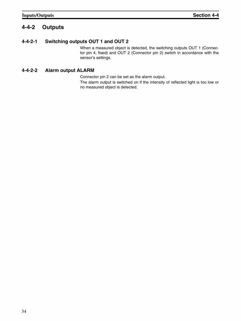
9-1-5 OPTIONS menu pathAll function options of the sensor are defined in the OPTIONS menu path.The Status LED is on.
Figure 4 OPTIONS menu path
r5Et Enter
Pin5 EnterSelectfunctionwith /
tchATeach input A
tchbTeach input B
tchCTeach input C
tchdTeach input D
tE5tTest input
tri6Trigger input
Enter
Pin2 Enter
n-P
EC0
Selectfunctionwith /
onECO-ModeON
oFFECO-ModeOFF
ti-1 Selectfunctionwith /
oFFSwitch-on / switch-offdelay OFF
on-1Switch-on / switch-offdelay NORMAL
on-2Switch-off delayMinimum pulse width
on-3Switch-off delaySingle pulse
ti-2 Selectfunctionwith /
oFFSwitch-on / switch-offdelay OFF
on-1Switch-on / switch-offdelay NORMAL
on-2Switch-off delayMinimum pulse width
on-3Switch-off delaySingle pulse
FLiP
0Pt Enter 2 s
Enter 2 sEnter 2 sEnter 2 s
Enter
Enter
Enter
Enter
Enter
Enter
Enter
Enter
Enter
Selectfunctionwith /
inInput
outOutput
Enter
Enter
Selectfunctionwith /
tchATeach input A
tchbTeach input B
tE5tTest input
tri6Trigger input
Enter
Selectfunctionwith /
out2Switchingoutput
ALArAlarm outputEnter
Selectfunctionwith /
PnPPlusswitching
nPnMinusswitching
coPLComple-mentary
Selectfunctionwith /
Enteruo
oFF
Selectfunctionwith /
Enter
Enter donE Enter
FunctionSwitch-on /switch-offdelayOutput 1
FunctionSwitch-on /switch-offdelayOutput 2 1.)
Menu items
Energy saving modeECO 2.)
Turn display
Outputstage
ResettoWorks default
FunctionConnector pin 2
FunctionConnector pin 5
Normaloperation
no
YE5Enter 2 s
Normaloperation
58

Setting the sensor using the push buttons Section 9-1
Remarks
1. If connector pin 2 is set as an input, the type of switch-on/off delay optioncan only be set for Output 1.
2. If the ECO energy saving mode is on, the display is switched off if no keysare pressed for about 5 minutes.The display is switched on again when any key is pressed.
59

Setting the sensor with a PC Section 9-2
9-2 Setting the sensor with a PCAll parameters of the sensor can also be set with a PC and the OMRON Sen-sorSupportSoftware S3.The connection between the sensor and the PC is established via an opticaldata interface. The data interface is clipped onto the sensor and should beconnected to a free COM port on the PC/laptop via the interface cable.
Data communication with the PC can be used for the following functions:
• Sensor set-up and configurations
• Real time readout • of the object distance• of switching states• of the stability• of the alarm outputs
• Monitoring and archiving the sensor data
• Updating the sensor firmwareA newer or customised version of the sensor's operating program can betransferred to the sensor.
Power supply voltage must be 16 V min. for firmware update.
Refer to the separate operating instructions ABBO 0018 for further informa-
tion on set-up with a PC and the SensorSupportSoftware S3.
60

SECTION 10Maintenance and Repair
10-1 Maintenance . . . . . . . . . . . . . . . . . . . . . . . . . . . . . . . . . . . . . . . . . . . . . . . . . . 6210-2 Repair . . . . . . . . . . . . . . . . . . . . . . . . . . . . . . . . . . . . . . . . . . . . . . . . . . . . . . . 62
61

Maintenance Section 10-1
10-1 MaintenanceAssembly, electrical connection and maintenance may only be carriedout by instructed, trained and authorised specialist personnel inaccordance with applicable regulations, after de-energising the powersupply and with the machine switched off.The machine must be safeguarded against reactivation.
Do not use any scratching or abrasive cleaning materials. The protec-tive pane of the optical system might get damaged.
The sensor requires no maintenance.
Remove dirt build up from the optical system and the display at regularintervals only with a soft, non abrasive fabric. Residual dirt may haveinfluence on the switching point and display accuracy.
10-2 RepairThe sensor, the optical data interface and the alignment tool may only berepaired by the manufacturer.Send in the sensor and the optical data interface tool to the supplier for repairalong with a description of the fault.
62

SECTION 11Accessories and Parts
11-1 Accessories and parts . . . . . . . . . . . . . . . . . . . . . . . . . . . . . . . . . . . . . . . . . . . 64
63

Accessories and parts Section 11-1
11-1 Accessories and parts
Description Article numberUniversal mounting bracket E39-EL1
Adapter bracket E39-EL2
IR data interface, cable length 2 m E3NT-AL232 2m
Straight cable socket, 5-pole, 2 m cable length XS2F-D521-DG0-A
Straight cable socket, 5-pole, 5 m cable length XS2F-D521-GG0-A
L-shaped cable socket, 5-pole 2 m cable length XS2F-D522-DG0-A
L-shaped cable socket, 5-pole 5 m cable length XS2F-D522-GG0-A
64

SECTION 12Appendix
12-1 Error messages . . . . . . . . . . . . . . . . . . . . . . . . . . . . . . . . . . . . . . . . . . . . . . . . 6612-2 Factory default settings . . . . . . . . . . . . . . . . . . . . . . . . . . . . . . . . . . . . . . . . . . 67
65

Error messages Section 12-1
12-1 Error messagesThe following error messages are shown on the sensor's display:
Display Meaning
The sensor does not detect an object
(flashing) Short-circuit at the output.The sensor continues normal functioning once the short-cir-cuit at the outputs has been remedied.
66

Factory default settings Section 12-2
12-2 Factory default settings
Parameter Factory default settings
Mode of Output 1 Background suppression BGS
Mode of Output 2 Background suppression BGS
Output function of Output 1 Light-on
Output function of Output 2 Light-on
Output switching PNP
Switch-on/off delayOutputs 1 and 2
OFF
Function of Connector pin 2 Output 2 (OUT 2)
Function of Connector pin 5 Teaching input (TEACH) for switching point A
Display in m
Energy saving mode OFF
Key lock OFF
67