Embed Size (px)
Citation preview

7/27/2019 E460en_07
http://slidepdf.com/reader/full/e460en07 1/38
Operator's manual
TruTool TF 350 (1A1), (1B1)

7/27/2019 E460en_07
http://slidepdf.com/reader/full/e460en07 2/38
Table of contents
1 Safety 41.1 General safety information 4
1.2 Specific safety information for jointing
presses
4
2 Description 6
2.1 Intended use 6
2.2 Technical data 7
2.3 Joining materials 8
Information concerning the workpiece and
the joint
9
2.4 Selecting processing strategy 11
2.5 Symbols 12
2.6 Noise and vibration information 13
3 Setting work 15
3.1 Setting the number of strokes 15
3.2 Select tool 15
Example 1 16
Example 2 173.3 Selecting tools for ventilation duct construc-
tion
18
4 Operation 19
4.1 Working with the TruTool TF 350 19
4.2 Overload protective device on the motor 21
4.3 Slewing r ing (optional) 22
4.4 STAND TruTool TF 350 (optional) 23
5 Maintenance 24
5.1 Replacing the tool 25
Cleaning the tool holder 25
Changing the punch arm 26
Changing the punch on the tilting arm 27
Replace die arm 28
Changing the die tilting arm 29
5.2 Lubricating the ram 31
5.3 Lubricating the coupling 31
2 Table of contents E460EN_07

7/27/2019 E460en_07
http://slidepdf.com/reader/full/e460en07 3/38
5.4 Replacing carbon brushes 33
6 Accessories and consumables 35
6.1 Ordering consumables 35
7 Appendix: Declaration of conformity, guar-
antee, replacement parts lists
37
E460EN_07 Table of contents 3

7/27/2019 E460en_07
http://slidepdf.com/reader/full/e460en07 4/38
1. Safety
1.1 General safety information
■ Read all the safety information and instructions includingthose in the brochure also supplied.
■ Failure to comply with the safety information and instructions
can cause electric shock, burns and/or serious injury.
■ Retain all the safety information and instructions for future
use.
Electrical voltage! Risk of fatal injury due to electric shock!
Ø Remove the plug from the plug socket before undertaking
any maintenance work on the machine.
Ø
Check the plug, cable and machine for damage each timebefore using the machine.
Ø Keep the machine dry and do not operate it in damp rooms.
Ø Connect the fault current (FI) circuit breaker with a maximum
breaking current of 30 mA when using the electric tool out-
side.
Ø Only use original TRUMPF accessories.
Damage to the machine due to improper handling.
Ø Wear safety glasses, hearing protection, protective gloves
and working shoes when working.Ø Connect the plug only when the machine is switched off.
Pull the power plug after use.
Ø Do not carry the machine by the cable.
Ø Have maintenance carried out by specialists.
1.2 Specific safety information for
jointing presses
Electrical voltage! Risk of fatal injury due to electric shock!
Ø Always lay the power cable away from the back of the
device and do not pull it over sharp edges.
Ø Do not perform any work that may cause the machine to
come into contact with hidden power lines or its own cable.
Contact with a live conductor can cause metallic machine
parts to become live and can lead to an electric shock.
4 Safety E460EN_07
DANGER
WARNING
DANGER

7/27/2019 E460en_07
http://slidepdf.com/reader/full/e460en07 5/38
Risk of injury to hands.
Ø Do not reach into the processing line with your hands.
Ø Use both hands to hold the machine.
Risk of injury from falling machinery
The entire weight of the machine must be taken up after
machining the workpiece.
Ø Use slewing ring (optional) with balancer.
E460EN_07 Specific safety information for jointing presses 5
WARNING
WARNING

7/27/2019 E460en_07
http://slidepdf.com/reader/full/e460en07 6/38
2. Description
1 Die arm, fixed
2 Tilting arm for the punch (com-
plete)
3 Grease nipples
4 Eccentric shaft
5 Button for triggering the stroke
6 Handle
7 On/Off switch
8 Speed control ler
9 Red indicator light (LED) "Motor
overload"
10 Tool carrier
Fig. 28214
2.1 Intended use
The TRUMPF jointing press TruTool TF 350 (1A1), (1B1) are an
electric hand tool used for the following applications:
■ Connecting sheet metal parts in overlapping alignment by
means of a cold forming process.
■ This process involved with this mechanical sheet joining tech-
nique is the "displacement jointing" (DIN 8593) manufacturing
method.
6 Description E460EN_07

7/27/2019 E460en_07
http://slidepdf.com/reader/full/e460en07 7/38
Characteristics
■ The joint arises during an uninterrupted ram stroke.
■ A movable punch and a fixed die together make up the set
of tools for this "one-step displacement joining".
■ The die consists of the fixed anvil, on which two lateral
spring-loaded non-rigid cutting segments are aligned.
■ A positive locking connection is created by this process (with-
out additional connection elements such as screws or rivets),
by means of a combined forming and shearing sequence
with a subsequent cold extrusion procedure.
■ Joining of both uncoated and coated workpieces.
■ Joining without application of heat.
■ No zinc vapors with galvanized sheets.
■ Joining of parts made of different sheet materials is possible.
■ Joining of two or three workpieces is possible.
■
No preliminary roughing or finishing.■ Work also possible in upside-down position.
Cross-section of the joint Tab. 1
2.2 Technical data
Other countries USAVoltage 230 V 120 V 110 V 120 V
Frequency 50/60 Hz 50/60 Hz 50/60 Hz 50/60 Hz
Permissible total material thick-
ness:
steel up to 400 N/mm2
3.5 mm 3.5 mm 3.5 mm 0.135 in
Permissible total material thick-
ness:
steel up to 600 N/mm2
2.5 mm 2.5 mm 2.5 mm 0.1 in
Permissible total material thick-
ness:
aluminum up to 250 N/mm2
4.0 mm 4.0 mm 4.0 mm 0.16 in
E460EN_07 Technical data 7

7/27/2019 E460en_07
http://slidepdf.com/reader/full/e460en07 8/38
Other countries USA
Min. total material thickness 0.8 mm 0.8 mm 0.8 mm 0.031 in
Max. jointing force 25 kN 25 kN 25 kN 5600 lbf
Nominal power consumption 1400 W 1400 W 1140 W 1200 W
Stroke cycle 2/s 2/s 2/s 2/s
Max. height of flange with
flanged material
36mm 36 mm 36mm 1.42 in
Weight 8.3 kg 8.3 kg 8.3 kg 18.4 lbs
Min. edge spacing 8mm 8 mm 8mm 0.315 in
Max. edge spacing 58mm 58 mm 58mm 2.28 in
Safety classII / II / II / II /
Tab. 2
2.3 Joining materials
1 Punch
2 Material, punching side
3 Material, die side
4 Cutting segment
5 Anvil
Tool and workpiece arrangement Fig. 100043
Cutting Fig. 10044
8 Joining materials E460EN_07

7/27/2019 E460en_07
http://slidepdf.com/reader/full/e460en07 9/38
Forming Fig. 10045
Note
Additional cutting and extruding merge together seamlessly dur-
ing the course of the stroke movement.
Information concerning the workpiece and
the joint
1 Punching side
2 Thicker workpiece
3 Thinner workpiece
4 Die side
Fig. 50427
■ Adjust the set of tools to match the material thickness
actually present.
■ In case of different material thicknesses, the thinner work-
piece has to be on the die side (see "Fig. 50427", pg. 9).
Joints can be achieved with material thickness differences of
up to ratios of approximately 1 : 2.
E460EN_07 Joining materials 9

7/27/2019 E460en_07
http://slidepdf.com/reader/full/e460en07 10/38
■ The thinner workpiece determines the maximum shear
strength of the component.
− Work with lubricants when processing aluminum and V2A
(increases service life).
■ The direction of the joint can be rotated by 90° (not possible
if "Plate for channel" (order no. 0243189) is used). For this,the die is mounted in the desired position and the punch is
aligned accordingly.
Note
The total material thickness measured counts as the recommen-
ded value for selecting the die arm. It is also possible to connect
more than two workpieces with each other. In general, the more
workpieces that are joined together, the less the holding force of
the joint/bond will be.
1 Die side
2 Joint
3 Punching side
X Joint width (= control dimen-
sion)
Fig. 50428
Die Total material thickness,steel Control dimension, jointwidth
1 1.5 mm 4.0 - 4.5 mm
2 2.0 mm 3.5 - 4.5 mm
2+ 2.5 mm 3.4 - 4.5 mm
3- 3.0 mm 3.8 - 4.5 mm
3 3.5 mm 3.6 - 4.5 mm
Tab. 3
10 Joining materials E460EN_07
Joint
7/27/2019 E460en_07
http://slidepdf.com/reader/full/e460en07 11/38
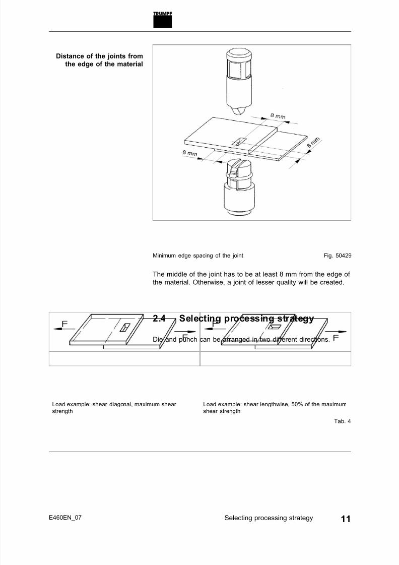
Minimum edge spacing of the joint Fig. 50429
The middle of the joint has to be at least 8 mm from the edge of
the material. Otherwise, a joint of lesser quality will be created.
2.4 Selecting processing strategy
Die and punch can be arranged in two different directions.
Load example: shear diagonal, maximum shear
strength
Load example: shear lengthwise, 50% of the maximum
shear strength
Tab. 4
E460EN_07 Selecting processing strategy 11
Distance of the joints from
the edge of the material

7/27/2019 E460en_07
http://slidepdf.com/reader/full/e460en07 12/38
F Breaking load in N
S Individual material thickness in
mm
Rm Tensile strength of the material
in N/mm²
Max. transferable lateral shearing forces depending on the
material thickness and the tensile strength of the material
Fig. 50430
A maximum shear strength is achieved from joining two materials
which each have:
■ have the same material stability.
■ have the same material thickness.
2.5 Symbols
Note
The following symbols are important for reading and understand-
ing the instruction manual. The correct interpretation of the sym-
bols will help you operate the machine better and safer.
Symbol Name Meaning
Read operating manual Read the operator's manual and safety information in
their entirety before starting up the machine. Closely
follow the instructions given.
Safety class II Indicates a doubly insulated tool.
Alternating current Type or property of current
V Volt Voltage
A Ampere Current, current input
Hz Hertz Frequency (oscillations per second)
W Watt Power, power input
mm Millimeters Dimensions e.g.: material thickness, chamfer length
12 Symbols E460EN_07
Maximum transferable shear
force

7/27/2019 E460en_07
http://slidepdf.com/reader/full/e460en07 13/38
Symbol Name Meaning
in Inch Dimensions e.g.: material thickness, chamfer length
no Idle speed Revolution speed without load
.../min Revolutions/strokes per minute Revolution speed, stroke rate per minute
Tab. 5
2.6 Noise and vibration information
Noise emission value may be exceeded.
Ø Wear hearing protection.
Vibration emission value may be exceeded.
Ø Select tools correctly and replace them promptly when they
show wear.
Ø Maintenance may be carried out by trained specialist techni-
cians only.
Ø Establish additional safety precautions for the protection of
the operator against the effects of vibrations (e.g. keeping
hands warm, organizing the work sequences, machining with
normal feed power).
Notes
■ The specified vibration emission value was measured in
accordance with a standardized testing procedure and can
be used to compare one electric tool with another.
■ The specified vibration emission value can also be applied
for a provisional estimate of the vibration load.
■ Times during which either the machine is switched off or run-
ning but not actually in use can considerably reduce the
vibration load during the entire working period.
■ Times during which the machine works independently and
self-propelled do not have to be calculated.
Designation of measured value Unit Value
according
to
EN 60745
Vibration emission value ah (vector sum of
three directions)
m/s2 2.6
Uncertainty K for vibration emission value m/s2 1.5
A-class acoustic pressure level LPA typi-
cally
dB (A) 84
A-class acoustic power level LWA typically dB (A) 95
E460EN_07 Noise and vibration information 13
WARNING
WARNING

7/27/2019 E460en_07
http://slidepdf.com/reader/full/e460en07 14/38
Designation of measured value Unit Value
according
to
EN 60745
Uncertainty K for noise emission value dB 1.5
Tab. 6
14 Noise and vibration information E460EN_07

7/27/2019 E460en_07
http://slidepdf.com/reader/full/e460en07 15/38
3. Setting work
3.1 Setting the number of strokes
Property damage resulting from incorrect alignment of the
tools!
Ø Check the alignment of punch and die (both lengthwise or
both diagonal).
1 Setting wheel for speed controller at motor
Fig. 64016
1. Setting wheel for speed controller on motor.
2. Reduced stroke rates result in:
− less engine noise.
− less heating and wearing on the gears.
− slightly increased jointing time.
3.2 Select tool
The TruTool TF 350 jointing press can be equipped with tools in
various ways depending on the particular application.
Five different types of dies are available to make it possible to
utilize tools corresponding to different types of materials and
material thicknesses.
A special tool holder belongs with each type of die (= fixed arm
or tilting arm), which is used as a receptacle for the die.
The following example help for the selection of the tools.
E460EN_07 Setting work 15
CAUTION

7/27/2019 E460en_07
http://slidepdf.com/reader/full/e460en07 16/38
Example 1
1 Die 2 Punch
Fig. 50433
1. Select material and total material thickness.
Total material thickness [mm]
Steel up to 400 N/mm² 0.8 - 1.5 1.6 - 2.0 2.1 - 2.5 2.6 - 3.0 3.0 - 3.5
Steel up to 600 N/mm² 0.8 - 1.5 1.6 - 2.0 2.1 - 2.5 - -
Non-ferrous heavy metal to250 N/mm²
0.8 - 1.0 1.1 - 2.0 2.1 - 3.0 3.1 - 4.0 -
Die arm label 1 2 3
Die no.
(Order number)
1
0111969
2
0111968
2+
0122272
3-
0053875
3
0111967
Tilting arm to die, cpl. no.
(order no.)
1
0128792
2
0128793
2+
0129723
3-
0129724
3
0128794
Die arm, fixed, cpl. no.
(order no.)
1
0118130
2
0118131
2+
0129763
3-
0129764
3
0118132
Fixed punch arm
(order no.)
0118129
Tab. 7
2. Find out which die is the right one from the table.
3. Select the die with fixed arm or with tilting arm.
4. Select fixed stamp arm (here standard).
16 Select tool E460EN_07
7/27/2019 E460en_07
http://slidepdf.com/reader/full/e460en07 17/38
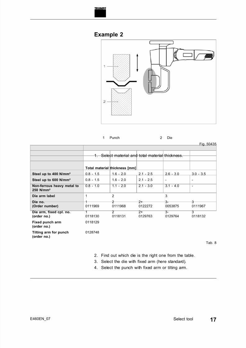
Example 2
1 Punch 2 Die
Fig. 50435
1. Select material and total material thickness.
Total material thickness [mm]
Steel up to 400 N/mm² 0.8 - 1.5 1.6 - 2.0 2.1 - 2.5 2.6 - 3.0 3.0 - 3.5
Steel up to 600 N/mm² 0.8 - 1.5 1.6 - 2.0 2.1 - 2.5 - -
Non-ferrous heavy metal to
250 N/mm²
0.8 - 1.0 1.1 - 2.0 2.1 - 3.0 3.1 - 4.0 -
Die arm label 1 2 3
Die no.
(Order number)
1
0111969
2
0111968
2+
0122272
3-
0053875
3
0111967
Die arm, fixed cpl. no.
(order no.)
1
0118130
2
0118131
2+
0129763
3-
0129764
3
0118132
Fixed punch arm
(order no.)
0118129
Tilting arm for punch
(order no.)
0128748
Tab. 8
2. Find out which die is the right one from the table.
3. Select the die with fixed arm (here standard).
4. Select the punch with fixed arm or tilting arm.
E460EN_07 Select tool 17

7/27/2019 E460en_07
http://slidepdf.com/reader/full/e460en07 18/38
3.3 Selecting tools for ventilation duct
construction
Whether or not the joint faces inwards (optical reasons) or out-
wards (fluidic reasons) depends on the respective tool set selec-ted for application.
The "plate for channel" makes it possible to have the joining on
the flange profiles. When doing this, joints are possible in the
depressions of the flange profiles.
Note
The joints with "Plate for channel" are only possible in the longi-
tudinal direction.
1 Channel
2 Tilting arm to the die
3 "Plate for channel" (0243189)
4 Lengthwise joints
5 "Stripper for channel" (0112929)
6 Punching arm, fixed
Tools for ventilation duct construction Fig. 50436
The "Stripper for channel" makes working across the corners
easier.
18 Selecting tools for ventilation duct construction E460EN_07

7/27/2019 E460en_07
http://slidepdf.com/reader/full/e460en07 19/38
4. Operation
Damage to the machine due to improper handling.
Ø Make sure the machine is always in a stable position when
operating it.Ø Never touch the tool while the machine is running.
Ø Always operate the machine away from your body.
Ø Do not operate the machine above your head.
Damage to property due to excessively high line voltage!
Motor damage.
Ø Check the power supply voltage. The power supply voltage
must correspond to the information on the nameplate of the
machine.
The appliance may switch off prematurely when affected by elec-
tromagnetic interference. The appliance will resume operation
when the faults have been cleared.
In order to improve the seaming result and increase the service
life of the punch, coat the seam point or the tool with oil before
processing the workpiece.
Material Oil
Steel, chro-
mium steel
Punching and nibbling oil (0.5 l, order no. 0103387)
Aluminum Punching and nibbling oil for aluminum (1 l, order no.
0125874)
Tab. 9
4.1 Working with the TruTool TF 350
Condition■ All setting work has been carried out.
Damage to property possible as a result of unnecessarily
long engine running times!
Ø Switch the machine off following processing.
E460EN_07 Operation 19
WARNING
CAUTION
Electromagnetic faults
Lubricating oil
CAUTION

7/27/2019 E460en_07
http://slidepdf.com/reader/full/e460en07 20/38
1 On/Off switch2 Button for triggering the stroke
3 Handle
Fig. 28377
1. Insert the mains plug.
2. Move the On/Off switch (1) to the front.
20 Operation E460EN_07
Switching on the machine

7/27/2019 E460en_07
http://slidepdf.com/reader/full/e460en07 21/38
Correct holding of the machine Fig. 50437
3. Triggering the stroke:− Actuate the button (2) which is located inside the handle
(3).
− If full revolution speed has been reached, trigger the
stroke.
4. Move the On/Off switch (1) to the rear.
5. Pull out the mains plug.
4.2 Overload protective device on the
motor
Note
If the motor temperature is too high, the motor will switch off.
The red indicator light (LED) on the motor lights up.
1. Allow the machine to run in idle until it has cooled down.
2. Operate the machine normally after it has cooled down.
E460EN_07 Operation 21
Switching off the machine

7/27/2019 E460en_07
http://slidepdf.com/reader/full/e460en07 22/38
4.3 Slewing ring (optional)
The machine can be swivelled into any processing position
desired with the help of the auxiliary "slewing ring" device (order
no. 0976671). The use of the slewing ring makes the work of the
machine operator easier.
The suspension of the slewing ring is done over as eyelet (total
weight of the machine TruTool TF 350 with slewing ring is
15 kg).
A balancer is used to provide optimal handling.
1 Plate
2 Screw
3 Clamping bracket
4 Tool carrier
TruTool TF 350 with installed slewing ring Fig. 50438
1. Align the machine in the plate (1) over the centering hole.
2. Clamp the machine on the tool carrier (4) in the clamping
bracket (3) and tighten the screw (2).
22 Operation E460EN_07

7/27/2019 E460en_07
http://slidepdf.com/reader/full/e460en07 23/38
4.4 STAND TruTool TF 350 (optional)
The joining station (order no. 1224803) is used for the stationary
operation of the TruTool TF 350 jointing press. This allows small
workpieces to be joined quickly and easier.
TruTool TF 350 with joining station Fig. 50439
E460EN_07 STAND TruTool TF 350 (optional) 23

7/27/2019 E460en_07
http://slidepdf.com/reader/full/e460en07 24/38
5. Maintenance
Electrical voltage! Risk of fatal injury due to electric shock!
Ø Remove the plug from the plug socket before undertaking
any maintenance work on the machine.Ø Check the plug, cable and machine for damage each time
before using the machine.
Ø Keep the machine dry and do not operate it in damp rooms.
Ø Connect the fault current (FI) circuit breaker with a maximum
breaking current of 30 mA when using the electric tool out-
side.
Ø Only use original TRUMPF accessories.
Risk of injury due to incorrect repair work
Machine does not work properly.
Ø Maintenance may be carried out by trained specialist techni-
cians only.
Damage to property caused by blunt tools!
Machine overload.
Ø Check the cutting edge of the punch hourly for wear. A
sharp punch produces good seaming results and prevents
machine damage. Change the punch in due time.
Maintenance point Interval Recommended
lubricants
Punch Change as needed. -
Die Change as needed. -
Tool carrier Clean as needed. -
Ventilation slots Clean as needed. -
Plunger Relubricate after 20 operat-
ing hours.
Lubricating grease
"G1"
Coupling Relubricate after 20 operat-
ing hours.
Lubricating grease
"G1"Gearbox and gear
head
After 300 operating hours,
arrange for a trained spe-
cialist to relubricate or to
replace the lubricating
grease.
Lubricating grease
"G1"
Maintenance points and intervals Tab. 10
24 Maintenance E460EN_07
DANGER
WARNING
CAUTION

7/27/2019 E460en_07
http://slidepdf.com/reader/full/e460en07 25/38
5.1 Replacing the tool
Cleaning the tool holder
1 Spring element (tilting arm)
(0249303)
2 Disc spring (0030678)
3 screw (fixed arm) (0111976)
Tool adapter Fig. 64014
1. Cleaning the tool holder.
2. Check for damage.
3. Lubricate location bolt with lubricating grease "G1" (order no.
344969).4. Mount the disc spring (2) on the screw (3) / the spring ele-
ment (1) as shown in the illustration.
5. Mount the tool arm on bolts.
6. Tighten screw (3) / spring element (1) firmly.
E460EN_07 Replacing the tool 25

7/27/2019 E460en_07
http://slidepdf.com/reader/full/e460en07 26/38
Changing the punch arm
1 Screw (0013897)
2 Punch (0110335)
3 Plastic stripper (0053649)
Fixed punch arm Fig. 50440
1. Remove the complete punch arm from the machine.2. Remove the stripper (3).
3. Loosen screw (1).
4. Pull out punch (2).
5. Install new punch.
6. Align punch (2).
7. Tighten screw (1) firmly.
26 Replacing the tool E460EN_07

7/27/2019 E460en_07
http://slidepdf.com/reader/full/e460en07 27/38
Changing the punch on the tilting arm
1 Screw (0983151)
2 Punch (0110335)
3 Plastic stripper (0053649)
Tilting arm on the punch Fig. 50441
1. Remove the complete punch arm from the machine.2. Remove the stripper (3).
3. Loosen screw (1).
4. Pull out punch (2).
5. Install new punch.
6. Align punch (2).
7. Tighten screw (1) firmly.
E460EN_07 Replacing the tool 27

7/27/2019 E460en_07
http://slidepdf.com/reader/full/e460en07 28/38
Replace die arm
1 Die
2 Plate (0063977)
3 Cap screw (0014400)
Fixed die arm Fig. 50442
1. Remove the complete fixed die arm from the machine.
2. Loosen cap screw (3).
3. Remove the plate (2).
4. Remove the die (1).
Note
Do not install the cutting segment backwards.
5. Install new die (be sure that the cutting segments fit closely
to the anvil).
28 Replacing the tool E460EN_07

7/27/2019 E460en_07
http://slidepdf.com/reader/full/e460en07 29/38
F: Cutting segment fits closely F: Cutting segment incorrectly
installed
Tab. 11
6. Install the plate (2).
7. Tighten screw (3) firmly.
Changing the die tilting arm
1 Die
2 Plate (0063977)
3 Cap screw (0014400)
Fig. 50443
E460EN_07 Replacing the tool 29

7/27/2019 E460en_07
http://slidepdf.com/reader/full/e460en07 30/38
1. Pull the bracket towards the front and swivel the whole fir
arm so that the cap screw (3) can be accessed.
2. Loosen cap screw (3).
3. Remove the plate (2).
4. Remove the die (1).
Note
Do not install the cutting segment backwards.
5. Install new die (be sure that the cutting segments fit closely
to the anvil).
F: Cutting segment fits closely F: Cutting segment incorrectly
installed
Tab. 12
6. Install the plate (2).
7. Tighten screw (3) firmly.
30 Replacing the tool E460EN_07

7/27/2019 E460en_07
http://slidepdf.com/reader/full/e460en07 31/38
5.2 Lubricating the ram
Fig. 64015
Ø Lubricate the grease nipple (S) on the tool with a grease
gun.
5.3 Lubricating the coupling
1. Pull the power plug out of the plug socket.
E460EN_07 Replacing the tool 31

7/27/2019 E460en_07
http://slidepdf.com/reader/full/e460en07 32/38
1 Sealing screw
Fig. 50449
2. Unscrew the screw plug (1).
2 Button for stroke triggering
(0053272)
3 Screwdriver at the eccentric
shaft (0110344)
Fig. 50448
3. Press and hold the button for stroke triggering (2) and rotate
the eccentric shaft (3) clockwise (see arrow at the machine's
face end) until the lubrication port becomes visible.
32 Replacing the tool E460EN_07

7/27/2019 E460en_07
http://slidepdf.com/reader/full/e460en07 33/38
or
Ø Put the grease gun through the bore hole in the end sign
and rotate the eccentric shaft clockwise until the grease
gun engages in the lubrication port.
4 Grease gun filled with "G1"
special (1398728)
5 Lubrication port
Fig. 50447
4. Relubricate the coupling with the grease gun (4) through the
lubrication port (5) (one stroke).5. Screw in the screw plug again.
6. Put the machine in a safe position.
7. Connect the power plug.
8. Switch on the motor.
The machine completes the stroke which was manually star-
ted.
9. Press the button for stroke triggering and trigger a test
stroke.
5.4 Replacing carbon brushes
The motor comes to a standstill whenever the carbon brushes
are worn out.
Note
For TRUMPF service addresses, see www.trumpf-power-
tools.com.
E460EN_07 Replacing the tool 33

7/27/2019 E460en_07
http://slidepdf.com/reader/full/e460en07 34/38
Ø Change the carbon brushes.
34 Replacing the tool E460EN_07

7/27/2019 E460en_07
http://slidepdf.com/reader/full/e460en07 35/38
6. Accessories and consumables
Consumables Order number Scope of delivery
Punch 0110335 X
Die no. 1 0111969 -Die no. 2 0111968 -
Die no. 2+ 0122272 -
Die no. 3- 0053875 -
Die no. 3 0111967 X
Stripper for flat materials 0053649 X
Stripper for channels 0112929 X
Grease gun filled with "G1" special 1398728 X
Punching and nibbling oil for steel (0.5 l) 0103387 X
Punching and nibbling oil for aluminum (1 l) 0125874 -
TruTool TF 350 Tab. 13
Accessories Order number Scope of delivery
Die arm fixed (complete)
No. 1
No. 2
No. 2+
No. 3-
No. 3
0118130
0118131
0129763
0129764
0118132
-
Tilting arm for die (complete)
No. 1
No. 2
No. 2+
No. 3-No. 3
0128792
0128793
0129723
01297240128794
-
Punch arm fixed (complete) 0118129 -
Tilting arm to the punch (complete) 0128748 -
Plate for channels 0243189 -
Operator's manual 0957263 X
Safety information, other countries 0125699 x
Safety information (red document), USA 1239438 X
Slewing ring 0976671 -
STAND TruTool TF 350 1224803 -
TruTool TF 350 Tab. 14
6.1 Ordering consumables
Note
The following data must be specified in order to ensure that
parts are delivered correctly and without delay.
1. Specify the order number.
E460EN_07 Accessories and consumables 35

7/27/2019 E460en_07
http://slidepdf.com/reader/full/e460en07 36/38
2. Enter further order data:
− Voltage data
− Quantity
− Machine type
3. Specify the complete shipping information:
− Correct address.
− Desired delivery type (e.g. air mail, courier, express mail,
ordinary freight, parcel post).
Note
For TRUMPF service addresses, see
www.trumpf ‑powertools.com.
4. Send the order to the TRUMPF representative office.
36 Accessories and consumables E460EN_07

7/27/2019 E460en_07
http://slidepdf.com/reader/full/e460en07 37/38
7. Appendix: Declaration of conformity,
guarantee, replacement parts lists
E460EN_07 Appendix: Declaration of conformity, guarantee,
replacement parts lists37

7/27/2019 E460en_07
http://slidepdf.com/reader/full/e460en07 38/38


