Embed Size (px)
Citation preview

E4H-CE AND E8-CE SERIESWATER PURIFICATION
MACHINES
3 m3/hr to 45 m3/hr18,000 gpd to 288,000 gpd
Control NarrativeManual

GE OSMONICS E4H-CE AND E8-CE WATERTREATMENT SYSTEMS
CONTROL NARRATIVEMANUAL
TABLE OF CONTENTS
Page
1.0 OVERVIEW 1
1.1 Hardware 11.2 Software 11.3 Operator Interface Terminal (OIT) 2
2.0 START-UP 3
2.1 Operation Screen 42.2 Alarm History Screen 62.3 Machine Status Screen 82.4 Utilities Screen 102.5 Set-Up Screen 11
LIST OF FIGURES
Figure Title
2.1 Start-Up Screen 32.2 Operation Screen 42.3 Alarm History Screen 62.4 Machine Status Screen 82.5 Utilities Screen 102.6 Set-Up Screen 11
LIST OF TABLES
Table Title
2.1 Alarm Messages 72.2 Status Screen System Message 9

1
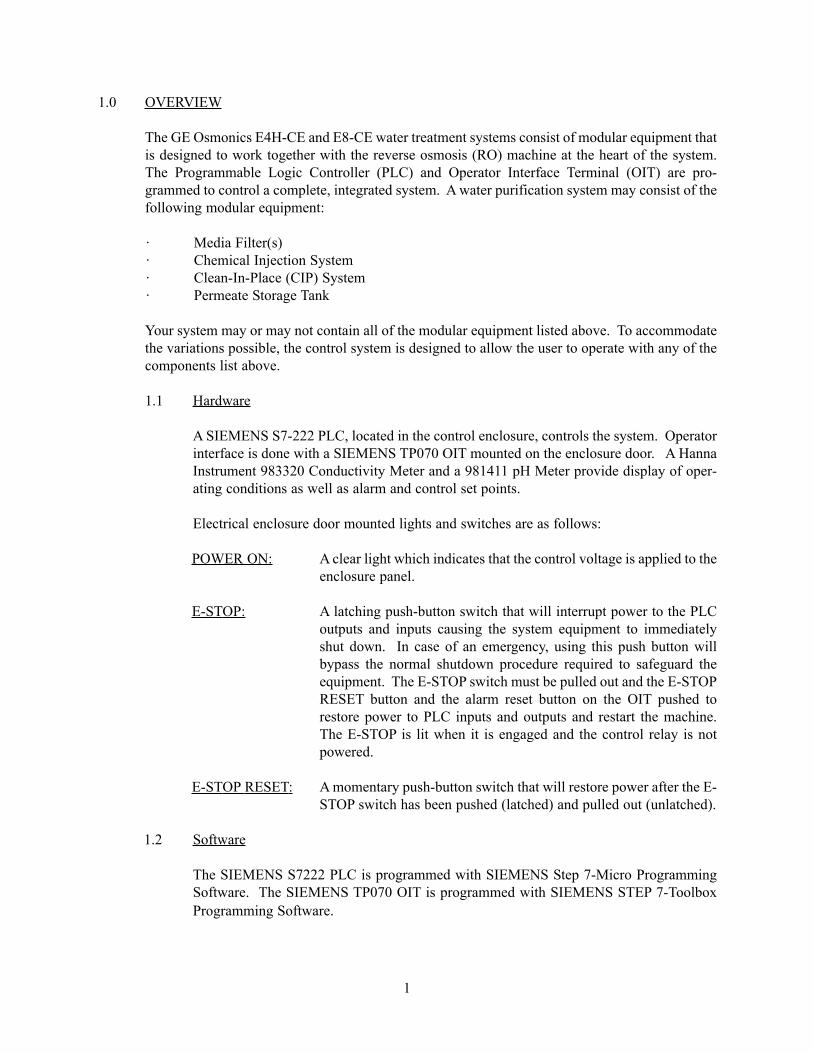
1.0 OVERVIEW
The GE Osmonics E4H-CE and E8-CE water treatment systems consist of modular equipment thatis designed to work together with the reverse osmosis (RO) machine at the heart of the system.The Programmable Logic Controller (PLC) and Operator Interface Terminal (OIT) are pro-grammed to control a complete, integrated system. A water purification system may consist of thefollowing modular equipment:
· Media Filter(s)· Chemical Injection System· Clean-In-Place (CIP) System· Permeate Storage Tank
Your system may or may not contain all of the modular equipment listed above. To accommodatethe variations possible, the control system is designed to allow the user to operate with any of thecomponents list above.
1.1 Hardware
A SIEMENS S7-222 PLC, located in the control enclosure, controls the system. Operatorinterface is done with a SIEMENS TP070 OIT mounted on the enclosure door. A HannaInstrument 983320 Conductivity Meter and a 981411 pH Meter provide display of oper-ating conditions as well as alarm and control set points.
Electrical enclosure door mounted lights and switches are as follows:
POWER ON: A clear light which indicates that the control voltage is applied to theenclosure panel.
E-STOP: A latching push-button switch that will interrupt power to the PLCoutputs and inputs causing the system equipment to immediatelyshut down. In case of an emergency, using this push button willbypass the normal shutdown procedure required to safeguard theequipment. The E-STOP switch must be pulled out and the E-STOPRESET button and the alarm reset button on the OIT pushed torestore power to PLC inputs and outputs and restart the machine.The E-STOP is lit when it is engaged and the control relay is notpowered.
E-STOP RESET: A momentary push-button switch that will restore power after the E-STOP switch has been pushed (latched) and pulled out (unlatched).
1.2 Software
The SIEMENS S7222 PLC is programmed with SIEMENS Step 7-Micro ProgrammingSoftware. The SIEMENS TP070 OIT is programmed with SIEMENS STEP 7-ToolboxProgramming Software.
2
1.3 Operator Interface Terminal (OIT) Screen
The available screens for the PanelView are as listed:
START-UP: Contact information for customer.
OPERATION: Gives run options for machine, alarm, and status messages.
ALARM HISTORY: Displays last five alarms conditions.
STATUS: Displays last five operating conditions.
UTILITIES: Adjusts contrast, screen center, and allows user to clean dis-play.
SET-UP: Allows user to clear alarm history, run time, and status.Allows user to download new program information.

3
2.0 START-UP
The START-UP Screen is displayed upon start-up of the E-CE Series RO machine. This touchscreen gives customer contact information.
Figure 2.1Start-Up Screen
To get to the next screen, press anywhere on the screen or wait twenty (20) seconds.
4
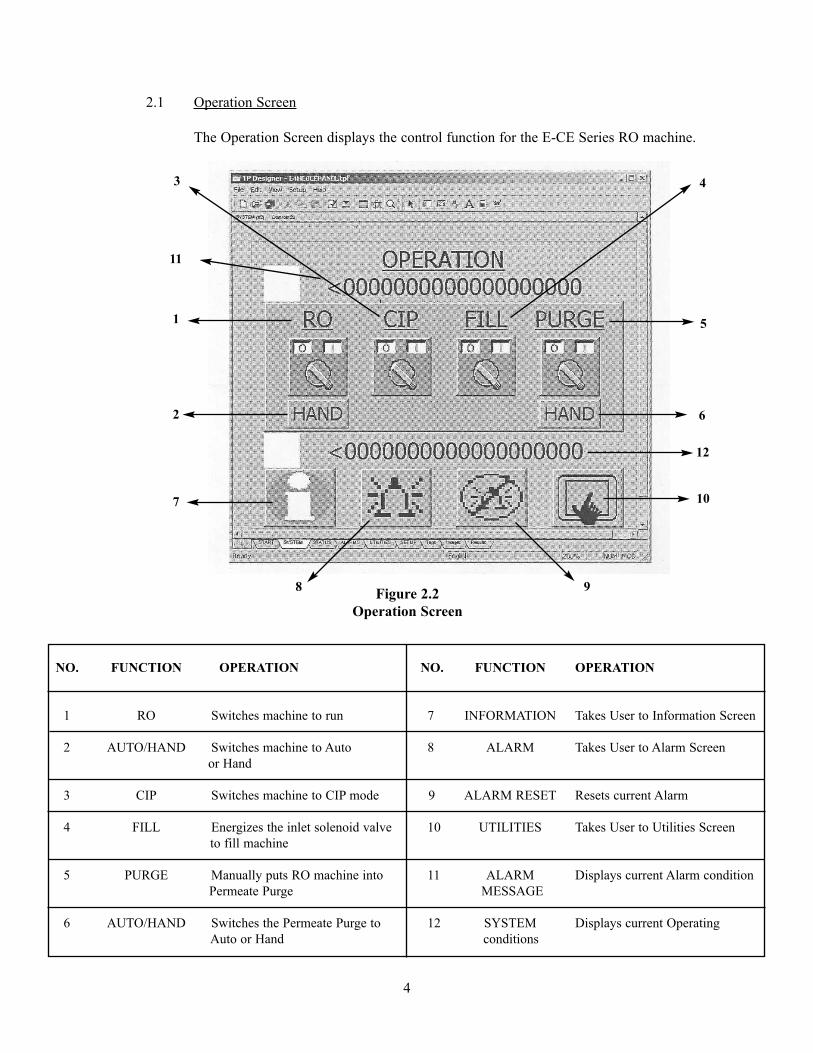
2.1 Operation Screen
The Operation Screen displays the control function for the E-CE Series RO machine.
Figure 2.2Operation Screen
NO. FUNCTION OPERATION
1 RO Switches machine to run
2 AUTO/HAND Switches machine to Autoor Hand
3 CIP Switches machine to CIP mode
4 FILL Energizes the inlet solenoid valve to fill machine
5 PURGE Manually puts RO machine into Permeate Purge
6 AUTO/HAND Switches the Permeate Purge to Auto or Hand
NO. FUNCTION OPERATION
7 INFORMATION Takes User to Information Screen
8 ALARM Takes User to Alarm Screen
9 ALARM RESET Resets current Alarm
10 UTILITIES Takes User to Utilities Screen
11 ALARM Displays current Alarm conditionMESSAGE
12 SYSTEM Displays current Operating conditions
11
3 4
6
7
8 9
10
5
12
2
1
5
The RO machine is controlled using the Operation Screen. The FILL button energizes theinlet solenoid valve allowing the RO machine to fill water. The machine will run for ten(10) minutes filling the machine. This needs to be done before the RO machine can oper-ate. Once the machine has been filled the RO, CIP, and PURGE buttons will operate.
The RO button controls the RO machine when it is in Run Mode. If the RO machine isnot in Run Mode, the RO button switches the RO machine from its current condition toRun Mode. In the AUTO position the RO machine will shut down without going intoPermeate Purge.
The CIP button controls the RO machine when it is in CIP Mode. If the machine is not inCIP Mode, pressing this button (CIP) will switch the machine from its current mode to CIPMode. See the Operation and Maintenance Manual (P/N 1161875) for details on runningCIP. If the machine is in CIP Mode, pressing the button shuts the RO machine down.
The PURGE Button controls the Permeate Purge Cycle of the RO machine. If the ROmachine is not in Purge Mode, pressing this button will switch the RO machine toPermeate Purge for ten (10) minutes and then turn the machine OFF. If the RO machineis in Purge Mode, pressing this button will shut down the machine.
The AUTO/HAND Button, located under the Purge Button, controls Permeate Purge oper-ation. In the HAND position the RO machine will only go into Permeate Purge by man-ually pressing the Purge Button. In the AUTO position, the RO machine will go intoPermeate Purge when the RO machine gets a signal from an external device, like a levelswitch.
The ALARM Button takes the user to the ALARM HISTORY Screen, described later(Section 2.3).
The INFORMATION Button takes the user to the MACHINE STATUS Screen, describedlater (Section 2.4).
The UTILITIES Button takes the user to the UTILITIES Screen, described later(Section 2.5).
The ALARM RESET Button is used to clear any alarm conditions, such as low inlet pres-sure, high permeate pressure, or motor overload. This button needs to be pressed beforethe RO machine will operate. The ALARM RESET Button on the Control Enclosure mayneed to be pressed as well.
The SYSTEM message, located under the Control Buttons, shows the user the current sta-tus of the machine. During shutdown, this message will display reason for shutdown.
6
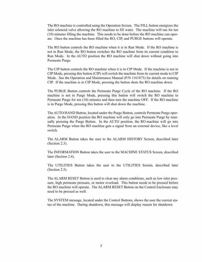
2.2 Alarm History Screen
The ALARM Message, located above the Control Buttons, shows the user current AlarmConditions.
Figure 2.3Alarm History Screen
NUMBER FUNCTION OPERATION
1 BACK Takes user back to OPERATION Screen
2 ALARM Takes user to ALARM Screen
3 ALARM RESET Resets current ALARM conditions
4 UTILITIES Takes users to UTILITIES Screen
5 ALARM HISTORY Displays the last 5 Alarm Conditions
3
5
4
2
1
7
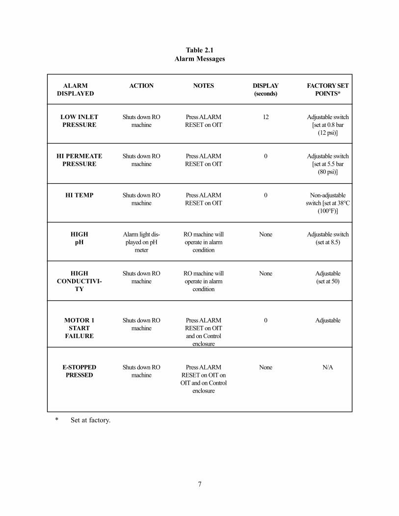
Table 2.1Alarm Messages
* Set at factory.
ALARMDISPLAYED
LOW INLETPRESSURE
HI PERMEATEPRESSURE
HI TEMP
HIGHpH
HIGHCONDUCTIVI-
TY
MOTOR 1START
FAILURE
E-STOPPEDPRESSED
ACTION
Shuts down ROmachine
Shuts down ROmachine
Shuts down ROmachine
Alarm light dis-played on pH
meter
Shuts down ROmachine
Shuts down ROmachine
Shuts down ROmachine
NOTES
Press ALARMRESET on OIT
Press ALARMRESET on OIT
Press ALARMRESET on OIT
RO machine willoperate in alarm
condition
RO machine willoperate in alarm
condition
Press ALARMRESET on OITand on Control
enclosure
Press ALARMRESET on OIT onOIT and on Control
enclosure
DISPLAY(seconds)
12
0
0
None
None
0
None
FACTORY SETPOINTS*
Adjustable switch[set at 0.8 bar
(12 psi)]
Adjustable switch[set at 5.5 bar
(80 psi)]
Non-adjustableswitch [set at 38°C
(100°F)]
Adjustable switch(set at 8.5)
Adjustable(set at 50)
Adjustable
N/A
8
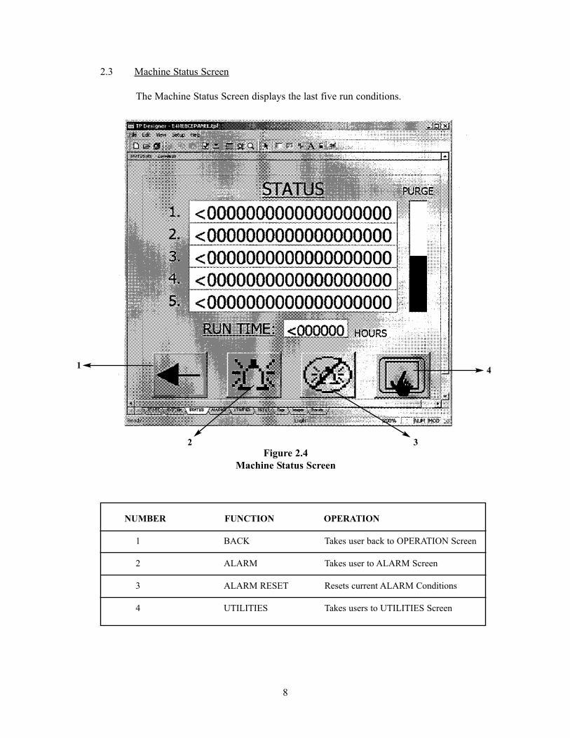
2.3 Machine Status Screen
The Machine Status Screen displays the last five run conditions.
Figure 2.4Machine Status Screen
NUMBER FUNCTION OPERATION
1 BACK Takes user back to OPERATION Screen
2 ALARM Takes user to ALARM Screen
3 ALARM RESET Resets current ALARM Conditions
4 UTILITIES Takes users to UTILITIES Screen
1
2 3
4
9
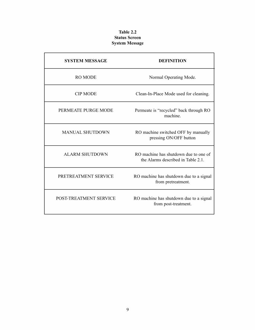
Table 2.2Status Screen
System Message
SYSTEM MESSAGE
RO MODE
CIP MODE
PERMEATE PURGE MODE
MANUAL SHUTDOWN
ALARM SHUTDOWN
PRETREATMENT SERVICE
POST-TREATMENT SERVICE
DEFINITION
Normal Operating Mode.
Clean-In-Place Mode used for cleaning.
Permeate is “recycled” back through ROmachine.
RO machine switched OFF by manuallypressing ON/OFF button
RO machine has shutdown due to one ofthe Alarms described in Table 2.1.
RO machine has shutdown due to a signalfrom pretreatment.
RO machine has shutdown due to a signalfrom post-treatment.
10
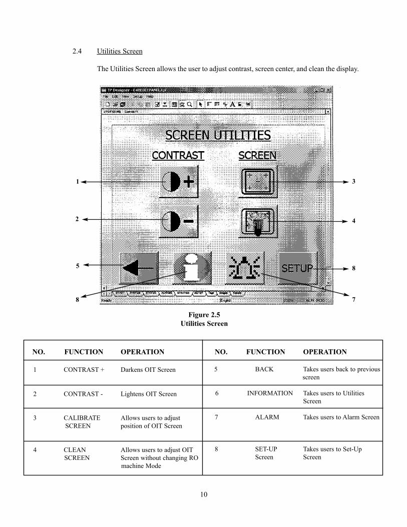
2.4 Utilities Screen
The Utilities Screen allows the user to adjust contrast, screen center, and clean the display.
Figure 2.5Utilities Screen
NO. FUNCTION OPERATION
1 CONTRAST + Darkens OIT Screen
2 CONTRAST - Lightens OIT Screen
3 CALIBRATE Allows users to adjustSCREEN position of OIT Screen
4 CLEAN Allows users to adjust OITSCREEN Screen without changing RO
machine Mode
NO. FUNCTION OPERATION
5 BACK Takes users back to previous screen
6 INFORMATION Takes users to Utilities Screen
7 ALARM Takes users to Alarm Screen
8 SET-UP Takes users to Set-UpScreen Screen
8
2
5
1
7
8
4
3
11
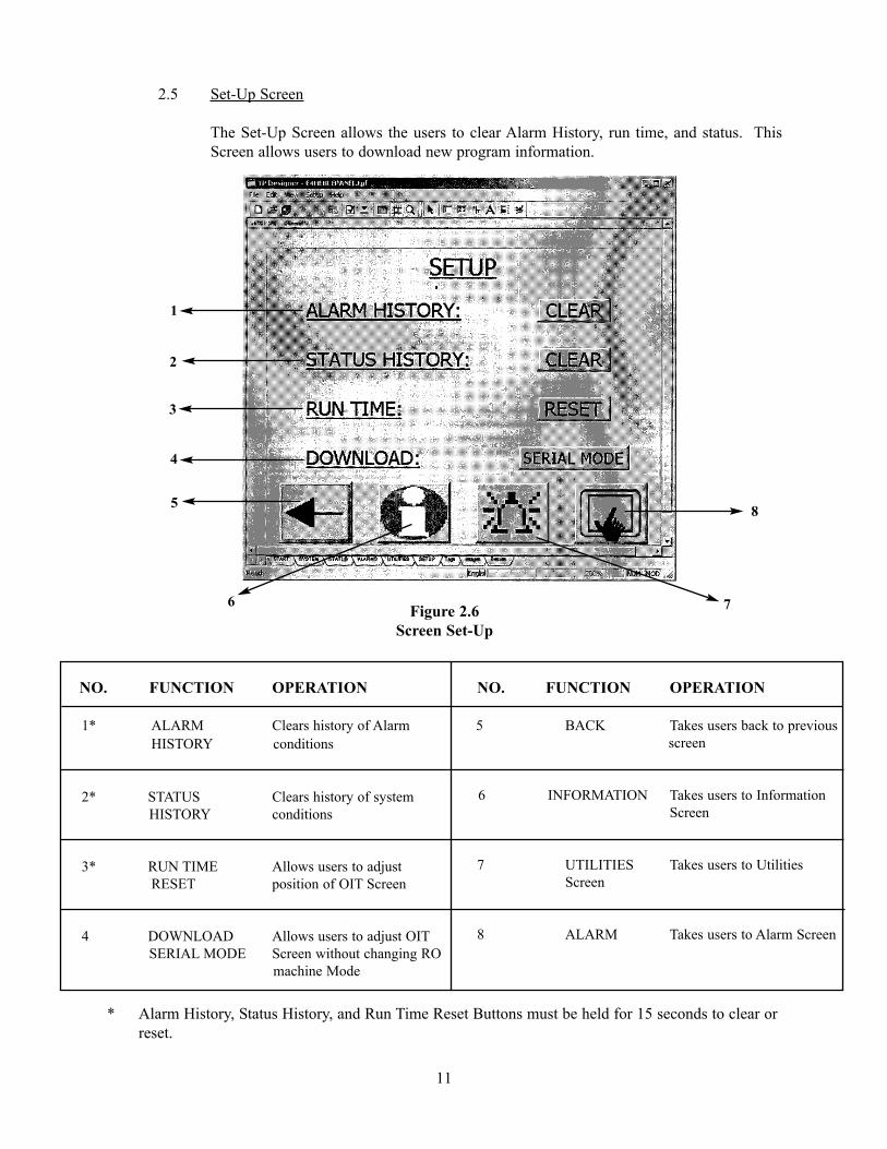
2.5 Set-Up Screen
The Set-Up Screen allows the users to clear Alarm History, run time, and status. ThisScreen allows users to download new program information.
Figure 2.6Screen Set-Up
* Alarm History, Status History, and Run Time Reset Buttons must be held for 15 seconds to clear orreset.
NO. FUNCTION OPERATION
1* ALARM Clears history of AlarmHISTORY conditions
2* STATUS Clears history of system HISTORY conditions
3* RUN TIME Allows users to adjustRESET position of OIT Screen
4 DOWNLOAD Allows users to adjust OITSERIAL MODE Screen without changing RO
machine Mode
NO. FUNCTION OPERATION
5 BACK Takes users back to previous screen
6 INFORMATION Takes users to Information Screen
7 UTILITIES Takes users to UtilitiesScreen
8 ALARM Takes users to Alarm Screen
2
3
4
5
1
6 7
8


Corporate Headquarters5951 Clearwater DriveMinnetonka, MN55343-8995USA(952) 933-2277 Phone(952) 933-0141 Fax
Euro/Africa Operations230 rue Robert SchumanZA des UsellesF-77350 Le MØe sur SeineFRANCE+33 1 64 10 2000 Phone+33 1 64 10 3747 Fax
Asia/Pacific Operations1044/8 SOI 44/2Sukhumvit Road PrakanongBangkok 10110THAILAND+66 2 38 14213 Phone+66 2 39 18183 Fax
Call (952) 933-2277 for additional information, (800) 766-2599 in the U.S., or visit w w w.osmonics.com
' Copyright 2002, GE Osmonics, Inc.Printed in USA, P/N 1233380 Rev. A
Manufactured in the USA