Embed Size (px)
Citation preview
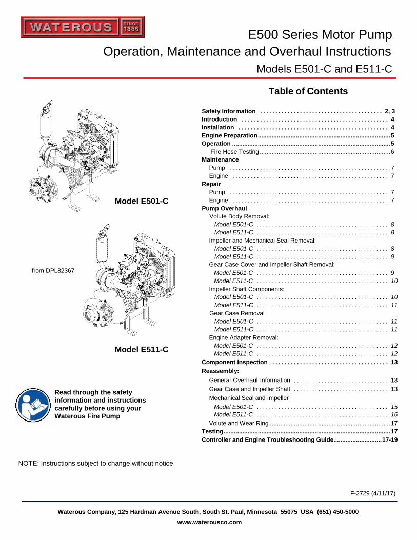
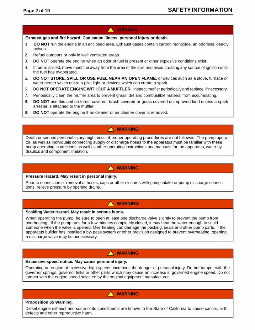
E500 Series Motor Pump
Operation, Maintenance and Overhaul Instructions
Models E501-C and E511-C
Table of Contents
Safety Information . . . . . . . . . . . . . . . . . . . . . . . . . . . . . . . . . . . . . . . . 2, 3
Introduction
Installation
. . . . . . . . . . . . . . . . . . . . . . . . . . . . . . . . . . . . . . . . . . . . . . . . 4
. . . . . . . . . . . . . . . . . . . . . . . . . . . . . . . . . . . . . . . . . . . . . . . . . 4
Engine Preparation ............................................................................. 5
Operation ............................................................................................ 5
Fire Hose Testing ............................................................................ 6
Maintenance
Model E501-C
Pump
Engine
Repair
Pump
Engine
. . . . . . . . . . . . . . . . . . . . . . . . . . . . . . . . . . . . . . . . . . . . . . . . . . . . 7
. . . . . . . . . . . . . . . . . . . . . . . . . . . . . . . . . . . . . . . . . . . . . . . . . . . 7
. . . . . . . . . . . . . . . . . . . . . . . . . . . . . . . . . . . . . . . . . . . . . . . . . . . . 7
. . . . . . . . . . . . . . . . . . . . . . . . . . . . . . . . . . . . . . . . . . . . . . . . . . . 7
Pump Overhaul
Volute Body Removal:
Model E501-C
Model E511-C
. . . . . . . . . . . . . . . . . . . . . . . . . . . . . . . . . . . . . . . . . . . 8
. . . . . . . . . . . . . . . . . . . . . . . . . . . . . . . . . . . . . . . . . . . 8
Impeller and Mechanical Seal Removal:
Model E501-C
Model E511-C
. . . . . . . . . . . . . . . . . . . . . . . . . . . . . . . . . . . . . . . . . . . 8
. . . . . . . . . . . . . . . . . . . . . . . . . . . . . . . . . . . . . . . . . . . 9
Gear Case Cover and Impeller Shaft Removal: from DPL82367 Model E501-C
Model E511-C
. . . . . . . . . . . . . . . . . . . . . . . . . . . . . . . . . . . . . . . . . . . 9
. . . . . . . . . . . . . . . . . . . . . . . . . . . . . . . . . . . . . . . . . . . 10
Impeller Shaft Components:
Model E501-C
Model E511-C
. . . . . . . . . . . . . . . . . . . . . . . . . . . . . . . . . . . . . . . . . . . 10
. . . . . . . . . . . . . . . . . . . . . . . . . . . . . . . . . . . . . . . . . . . 11
Gear Case Removal
Model E501-C
Model E511-C
. . . . . . . . . . . . . . . . . . . . . . . . . . . . . . . . . . . . . . . . . . . 11
. . . . . . . . . . . . . . . . . . . . . . . . . . . . . . . . . . . . . . . . . . . 11
Engine Adapter Removal:
Model E511-C Model E501-C
Model E511-C
. . . . . . . . . . . . . . . . . . . . . . . . . . . . . . . . . . . . . . . . . . . 12
. . . . . . . . . . . . . . . . . . . . . . . . . . . . . . . . . . . . . . . . . . . 12
Component Inspection
Reassembly:
. . . . . . . . . . . . . . . . . . . . . . . . . . . . . . . . . . . . . . 13
Read through the safety information and instructions
General Overhaul Information
Gear Case and Impeller Shaft
Mechanical Seal and Impeller
. . . . . . . . . . . . . . . . . . . . . . . . . . . . . . . 13
. . . . . . . . . . . . . . . . . . . . . . . . . . . . . . . 13
carefully before using your Waterous Fire Pump
Model E501-C
Model E511-C
. . . . . . . . . . . . . . . . . . . . . . . . . . . . . . . . . . . . . . . . . . . 15
. . . . . . . . . . . . . . . . . . . . . . . . . . . . . . . . . . . . . . . . . . . 16
Volute and Wear Ring ...................................................................... 17
Testing ................................................................................................. 17
Controller and Engine Troubleshooting Guide............................ 17-19
NOTE: Instructions subject to change without notice
F-2729 (4/11/17)
Waterous Company, 125 Hardman Avenue South, South St. Paul, Minnesota 55075 USA (651) 450-5000
www.waterousco.com
Page 2 of 19 SAFETY INFORMATION
! WARNING
Proposition 65 Warning.
Diesel engine exhaust and some of its constituents are known to the State of California to cause cancer, birth defects and other reproductive harm.
! WARNING
Excessive speed notice. May cause personal injury.
Operating an engine at excessive high speeds increases the danger of personal injury. Do not tamper with the governor springs, governor links or other parts which may cause an increase in governed engine speed. Do not tamper with the engine speed selected by the original equipment manufacturer.
! WARNING
Scalding Water Hazard. May result in serious burns.
When operating the pump, be sure to open at least one discharge valve slightly to prevent the pump from overheating. If the pump runs for a few minutes completely closed, it may heat the water enough to scald someone when the valve is opened. Overheating can damage the packing, seals and other pump parts. If the apparatus builder has installed a by --- pass system or other provision designed to prevent overheating, opening a discharge valve may be unnecessary.
! WARNING
Pressure Hazard. May result in personal injury.
Prior to connection or removal of hoses, caps or other closures with pump intake or pump discharge connec- tions, relieve pressure by opening drains.
! WARNING
Death or serious personal injury might occur if proper operating procedures are not followed. The pump opera- tor, as well as individuals connecting supply or discharge hoses to the apparatus must be familiar with these pump operating instructions as well as other operating instructions and manuals for the apparatus, water hy- draulics and component limitation.
! DANGER
Exhaust gas and fire hazard. Can cause illness, personal injury or death.
1. DO NOT run the engine in an enclosed area. Exhaust gases contain carbon monoxide, an odorless, deadly poison.
2. Refuel outdoors or only in well ventilated areas.
3. DO NOT operate the engine when an odor of fuel is present or other explosive conditions exist.
4. If fuel is spilled, move machine away from the area of the spill and avoid creating any source of ignition until the fuel has evaporated.
5. DO NOT STORE, SPILL OR USE FUEL NEAR AN OPEN FLAME, or devices such as a stove, furnace or water heater which utilize a pilot light or devices which can create a spark.
6. DO NOT OPERATE ENGINE WITHOUT A MUFFLER. Inspect muffler periodically and replace, if necessary.
7. Periodically clean the muffler area to prevent grass, dirt and combustible material from accumulating.
8. DO NOT use this unit on forest covered, brush covered or grass covered unimproved land unless a spark arrester is attached to the muffler.
9. DO NOT operate the engine if air cleaner or air cleaner cover is removed.
SAFETY INFORMATION Page 3 of 19
WARNING
Hose Testing Hazard. May result in serious personal injury. Due to a potential for catastrophic hose failure during service testing of fire hose, it is vital that safety precautions be taken to prevent exposure of anyone to this danger. Fire pumps on fire department apparatus are not designed for and should not be used for service testing of fire hoses. Hose testing machines should be used for service testing of fire hoses.
WARNING
Pressure Hazard. May result in serious personal injury. If a fire pump on a fire department apparatus is used for service testing of fire hoses, the procedures in NFPA 1962 MUST be followed including the use of a fire department gate valve with a ¼-inch (6 mm) hole drilled through the gate installed between the fire apparatus discharge outlet and the hose test layout to prevent a volume surge from the pump in the event a hose bursts during testing.
WARNING
Scalding Water Hazard. May result in serious burns. If a fire pump on a fire department apparatus is used for service testing of fire hoses, pump discharge water must be circulated through a by-pass system or discharged through a slightly open discharge valve, or some other provision must be used to prevent overheating. If the pump runs for a few minutes without adequate flow through the pump, water may be heated enough to scald someone when a valve is opened.
! WARNING
Moving or rotating parts hazard. May cause personal injury.
Always keep hands and feet clear of moving or rotating parts to prevent injury.
! WARNING
Spark arrestor notice.
If this engine is equipped with a spark arrestor for use on forest covered, brush covered unimproved land, it must be maintained in effective working order by the operator. In the state of California, the above is required by law (Section 4442 of the California Public Resources Code.) Other states may have similar laws.
! WARNING
Accidental starting hazard. May cause personal injury to the hand, arm or feet.
When servicing the engine or equipment, always disconnect the negative wire from the battery terminal to prevent accidental starting.
! WARNING
High temperature components. May cause severe burns.
Do not touch hot mufflers, cylinders or fins as contact may cause burns.
Page 4 of 19
INTRODUCTION
Waterous E500 Motor Pumps are gear driven centrifu- gal pumps powered by a three-cylinder, diesel Kubota engine.
An optional remotely mountable instrument panel and a priming system consisting of either a Waterous' hand or electric primer are available.
The model numbers below define the different pump designations.
Table 1. Pump Model Designations
INSTALLATION
1. Battery cable - The correct wire gage depends on the length of cable needed. Use the following chart to determine what size battery cable to use:
These instructions are to be used for placing the pumping unit into operation, maintenance and repair of the pump. Refer to the Kubota Operation and Main- tenance instructions for maintenance of the engine. Major repairs of the engine can be taken care of by an authorized Kubota dealership.
2. Fuel line - Route the fuel line from the fuel tank (not supplied by Waterous) such that low pockets in which water could accumulate and freeze, and high pockets where fuel vapors could collect and restrict the flow of liquid fuel (vapor lock) are elimi- nated. Avoid potential rubbing and high heat areas, and use adequate connectors and re- straints to avoid accidental disconnecting of fuel lines.
3. The maximum vertical lift the fuel pump can achieve is two feet (610 mm) with any length fuel line. On diesel engines, be sure the return line reaches the bottom of the fuel tank to prevent air bubbles (see pump dimensional drawing for fuel return outlet on engine).
4. Mounting - Kubota recommends an isolation mount for the engine to minimize vibration.
5. Air Flow - keep the front of the radiator unob- structed to allow for adequate air flow. The fan pulls air across the radiator and then pushes the outside air over the engine.
6. Priming system - See optional priming pump in- struction, F-1031, Section 3006, Priming System Installation Instructions.
7. Emission label - If emission control label, located on engine cylinder head, is not visible on engine after installation, the loose label provided must be applied such that it is visible when engine is ac- cessed, per EPA/CARB requirements.
Pump Model
Instrument Panel
Engine Type Intake Discharge
E501-C Single or Dual Diesel 2” female
NPT 1-1/2” female
NPT
E511-C Single or Dual Diesel 3” female
NPT 2” female NPT
Maximum Length (ft.) Minimum Wire Gage Size
2 4 3.5 2 4 1
5.5 1/0 7 2/0
8.5 3/0 11 4/0
CAUTION
The pump is equipped with a mechanical seal. Excessive heat generated by running the pump dry may damage seal.
Page 5 of 19
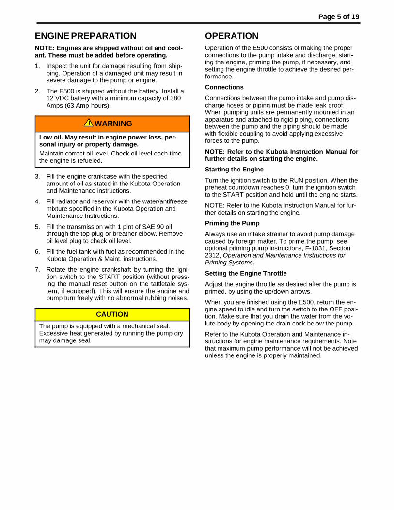
ENGINE PREPARATION
NOTE: Engines are shipped without oil and cool- ant. These must be added before operating.
1. Inspect the unit for damage resulting from ship- ping. Operation of a damaged unit may result in severe damage to the pump or engine.
2. The E500 is shipped without the battery. Install a 12 VDC battery with a minimum capacity of 380 Amps (63 Amp-hours).
3. Fill the engine crankcase with the specified amount of oil as stated in the Kubota Operation and Maintenance instructions.
4. Fill radiator and reservoir with the water/antifreeze mixture specified in the Kubota Operation and Maintenance Instructions.
5. Fill the transmission with 1 pint of SAE 90 oil through the top plug or breather elbow. Remove oil level plug to check oil level.
6. Fill the fuel tank with fuel as recommended in the Kubota Operation & Maint. instructions.
7. Rotate the engine crankshaft by turning the igni- tion switch to the START position (without press- ing the manual reset button on the tattletale sys- tem, if equipped). This will ensure the engine and pump turn freely with no abnormal rubbing noises.
OPERATION
Operation of the E500 consists of making the proper connections to the pump intake and discharge, start- ing the engine, priming the pump, if necessary, and setting the engine throttle to achieve the desired per- formance.
Connections
Connections between the pump intake and pump dis- charge hoses or piping must be made leak proof. When pumping units are permanently mounted in an apparatus and attached to rigid piping, connections between the pump and the piping should be made with flexible coupling to avoid applying excessive forces to the pump.
NOTE: Refer to the Kubota Instruction Manual for further details on starting the engine.
Starting the Engine
Turn the ignition switch to the RUN position. When the preheat countdown reaches 0, turn the ignition switch to the START position and hold until the engine starts.
NOTE: Refer to the Kubota Instruction Manual for fur- ther details on starting the engine.
Priming the Pump
Always use an intake strainer to avoid pump damage caused by foreign matter. To prime the pump, see optional priming pump instructions, F-1031, Section 2312, Operation and Maintenance Instructions for Priming Systems.
Setting the Engine Throttle
Adjust the engine throttle as desired after the pump is primed, by using the up/down arrows.
When you are finished using the E500, return the en- gine speed to idle and turn the switch to the OFF posi- tion. Make sure that you drain the water from the vo- lute body by opening the drain cock below the pump.
Refer to the Kubota Operation and Maintenance in- structions for engine maintenance requirements. Note that maximum pump performance will not be achieved unless the engine is properly maintained.
! WARNING
Low oil. May result in engine power loss, per- sonal injury or property damage.
Maintain correct oil level. Check oil level each time the engine is refueled.
Page 6 of 19
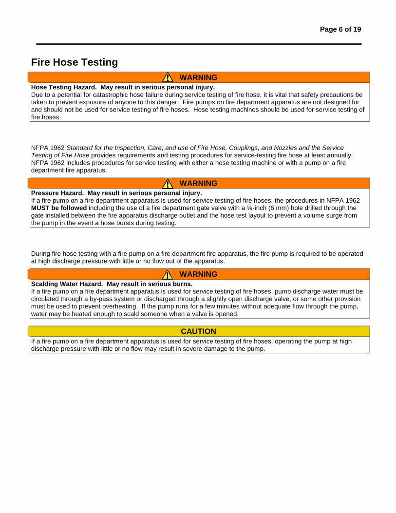
Fire Hose Testing
WARNING
Hose Testing Hazard. May result in serious personal injury. Due to a potential for catastrophic hose failure during service testing of fire hose, it is vital that safety precautions be taken to prevent exposure of anyone to this danger. Fire pumps on fire department apparatus are not designed for and should not be used for service testing of fire hoses. Hose testing machines should be used for service testing of fire hoses.
NFPA 1962 Standard for the Inspection, Care, and use of Fire Hose, Couplings, and Nozzles and the Service Testing of Fire Hose provides requirements and testing procedures for service-testing fire hose at least annually. NFPA 1962 includes procedures for service testing with either a hose testing machine or with a pump on a fire department fire apparatus.
WARNING
Pressure Hazard. May result in serious personal injury. If a fire pump on a fire department apparatus is used for service testing of fire hoses, the procedures in NFPA 1962 MUST be followed including the use of a fire department gate valve with a ¼-inch (6 mm) hole drilled through the gate installed between the fire apparatus discharge outlet and the hose test layout to prevent a volume surge from the pump in the event a hose bursts during testing.
During fire hose testing with a fire pump on a fire department fire apparatus, the fire pump is required to be operated at high discharge pressure with little or no flow out of the apparatus.
WARNING
Scalding Water Hazard. May result in serious burns. If a fire pump on a fire department apparatus is used for service testing of fire hoses, pump discharge water must be circulated through a by-pass system or discharged through a slightly open discharge valve, or some other provision must be used to prevent overheating. If the pump runs for a few minutes without adequate flow through the pump, water may be heated enough to scald someone when a valve is opened.
CAUTION
If a fire pump on a fire department apparatus is used for service testing of fire hoses, operating the pump at high discharge pressure with little or no flow may result in severe damage to the pump.

Page 7 of 19
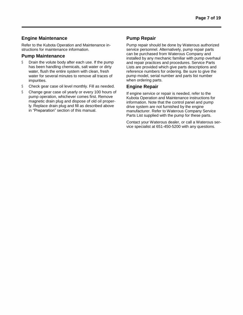
Engine Maintenance
Refer to the Kubota Operation and Maintenance in- structions for maintenance information.
Pump Maintenance
S Drain the volute body after each use. If the pump has been handling chemicals, salt water or dirty water, flush the entire system with clean, fresh water for several minutes to remove all traces of impurities.
S Check gear case oil level monthly. Fill as needed.
S Change gear case oil yearly or every 100 hours of pump operation, whichever comes first. Remove magnetic drain plug and dispose of old oil proper- ly. Replace drain plug and fill as described above in “Preparation” section of this manual.
Pump Repair
Pump repair should be done by Waterous authorized service personnel. Alternatively, pump repair parts can be purchased from Waterous Company and installed by any mechanic familiar with pump overhaul and repair practices and procedures. Service Parts Lists are provided which give parts descriptions and reference numbers for ordering. Be sure to give the pump model, serial number and parts list number when ordering parts.
Engine Repair
If engine service or repair is needed, refer to the Kubota Operation and Maintenance instructions for information. Note that the control panel and pump drive system are not furnished by the engine manufacturer. Refer to Waterous Company Service Parts List supplied with the pump for these parts.
Contact your Waterous dealer, or call a Waterous ser- vice specialist at 651-450-5200 with any questions.
PUMP OVERHAUL Page 8 of 19
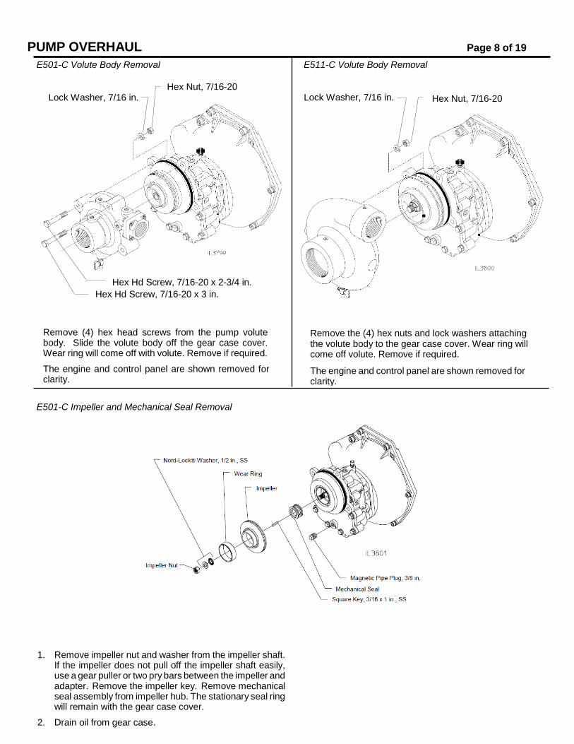
E501-C Impeller and Mechanical Seal Removal
1. Remove impeller nut and washer from the impeller shaft. If the impeller does not pull off the impeller shaft easily, use a gear puller or two pry bars between the impeller and adapter. Remove the impeller key. Remove mechanical seal assembly from impeller hub. The stationary seal ring will remain with the gear case cover.
2. Drain oil from gear case.
E501-C Volute Body Removal E511-C Volute Body Removal
Hex Nut, 7/16-20 Lock Washer, 7/16 in. Lock Washer, 7/16 in. Hex Nut, 7/16-20
Hex Hd Screw, 7/16-20 x 2-3/4 in.
Hex Hd Screw, 7/16-20 x 3 in.
Remove (4) hex head screws from the pump volute body. Slide the volute body off the gear case cover. Wear ring will come off with volute. Remove if required.
The engine and control panel are shown removed for clarity.
Remove the (4) hex nuts and lock washers attaching the volute body to the gear case cover. Wear ring will come off volute. Remove if required.
The engine and control panel are shown removed for clarity.
PUMP OVERHAUL
Page 9 of 19
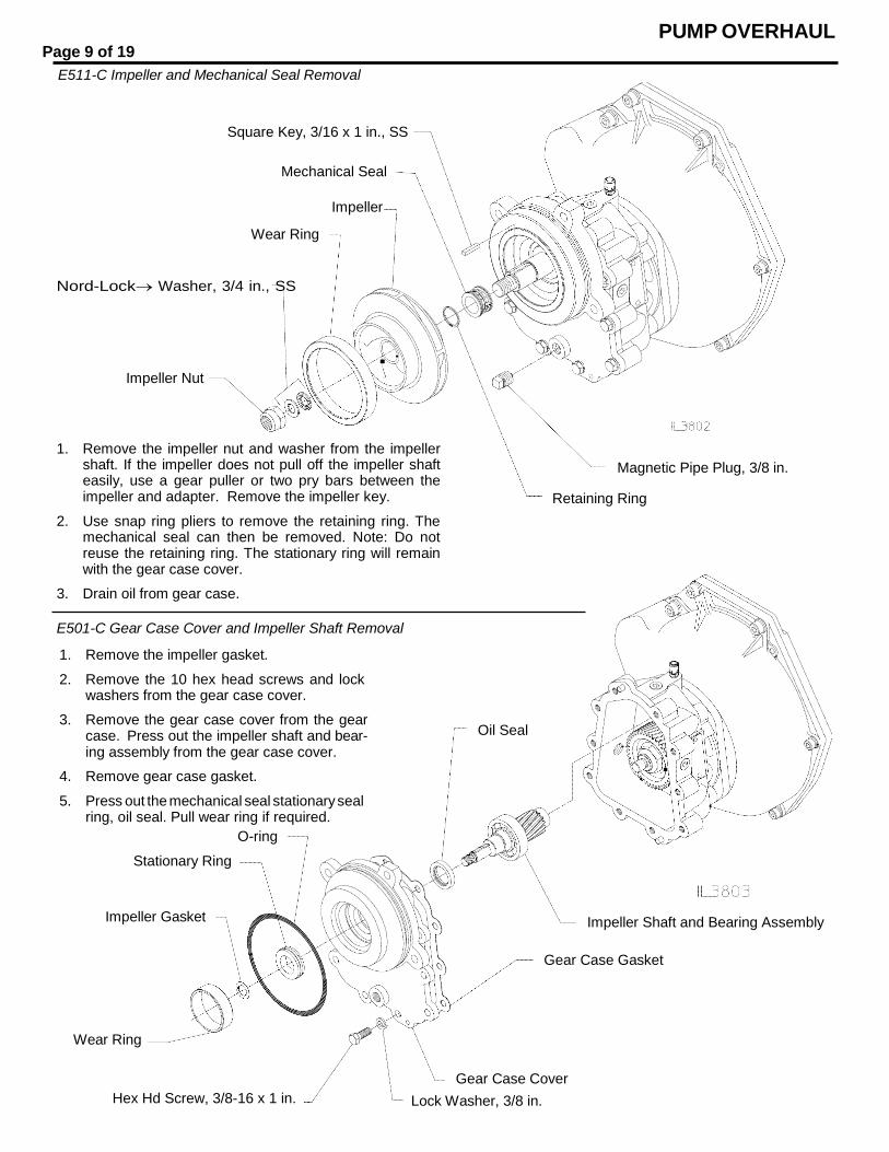
E511-C Impeller and Mechanical Seal Removal
Square Key, 3/16 x 1 in., SS
Mechanical Seal
Wear Ring
Impeller
Nord-LockWasher, 3/4 in., SS
Impeller Nut
1. Remove the impeller nut and washer from the impeller shaft. If the impeller does not pull off the impeller shaft easily, use a gear puller or two pry bars between the impeller and adapter. Remove the impeller key.
2. Use snap ring pliers to remove the retaining ring. The mechanical seal can then be removed. Note: Do not reuse the retaining ring. The stationary ring will remain with the gear case cover.
3. Drain oil from gear case.
Magnetic Pipe Plug, 3/8 in.
Retaining Ring
E501-C Gear Case Cover and Impeller Shaft Removal
1. Remove the impeller gasket.
2. Remove the 10 hex head screws and lock washers from the gear case cover.
3. Remove the gear case cover from the gear case. Press out the impeller shaft and bear- ing assembly from the gear case cover.
4. Remove gear case gasket.
5. Press out the mechanical seal stationary seal ring, oil seal. Pull wear ring if required.
O-ring
Oil Seal
Stationary Ring
Impeller Gasket Impeller Shaft and Bearing Assembly
Gear Case Gasket
Wear Ring
Hex Hd Screw, 3/8-16 x 1 in.
Gear Case Cover
Lock Washer, 3/8 in.
PUMP OVERHAUL Page 10 of 19
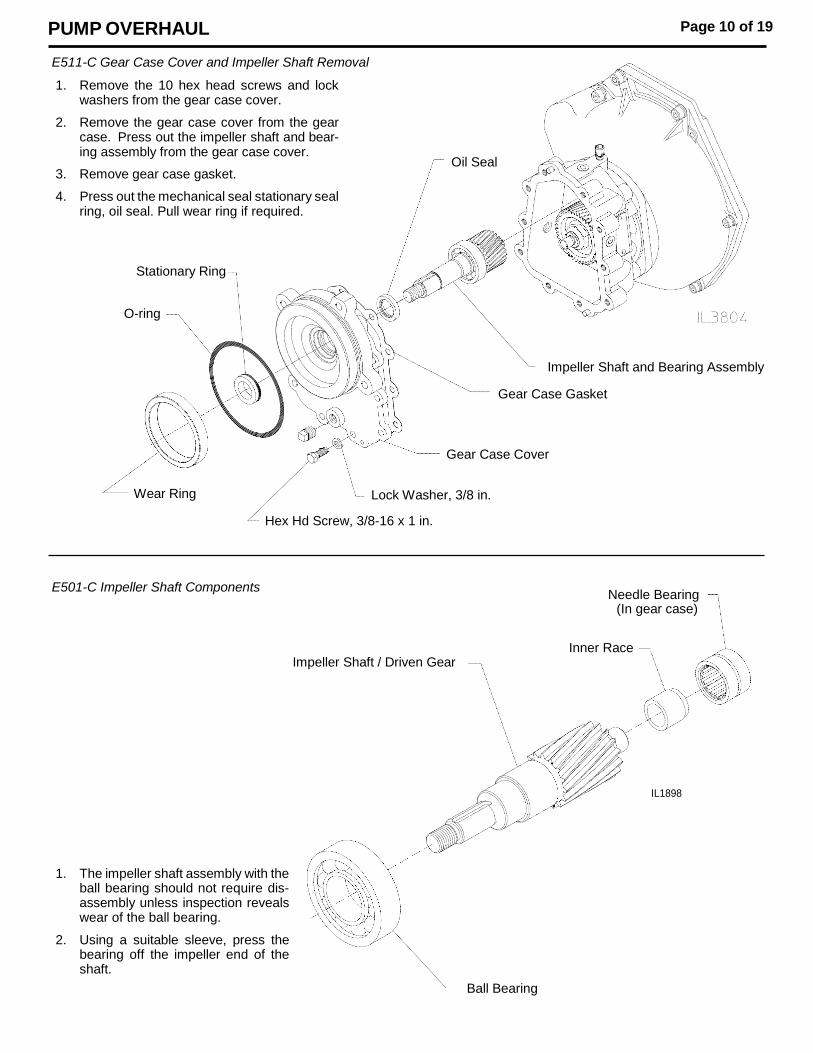
E511-C Gear Case Cover and Impeller Shaft Removal
1. Remove the 10 hex head screws and lock washers from the gear case cover.
2. Remove the gear case cover from the gear case. Press out the impeller shaft and bear- ing assembly from the gear case cover.
3. Remove gear case gasket.
4. Press out the mechanical seal stationary seal ring, oil seal. Pull wear ring if required.
Oil Seal
Stationary Ring
O-ring
Impeller Shaft and Bearing Assembly
Gear Case Gasket
Gear Case Cover
Wear Ring Lock Washer, 3/8 in.
Hex Hd Screw, 3/8-16 x 1 in.
E501-C Impeller Shaft Components
Needle Bearing (In gear case)
Impeller Shaft / Driven Gear
Inner Race
IL1898
1. The impeller shaft assembly with the ball bearing should not require dis- assembly unless inspection reveals wear of the ball bearing.
2. Using a suitable sleeve, press the bearing off the impeller end of the shaft.
Ball Bearing
PUMP OVERHAUL
Page 11 of 19
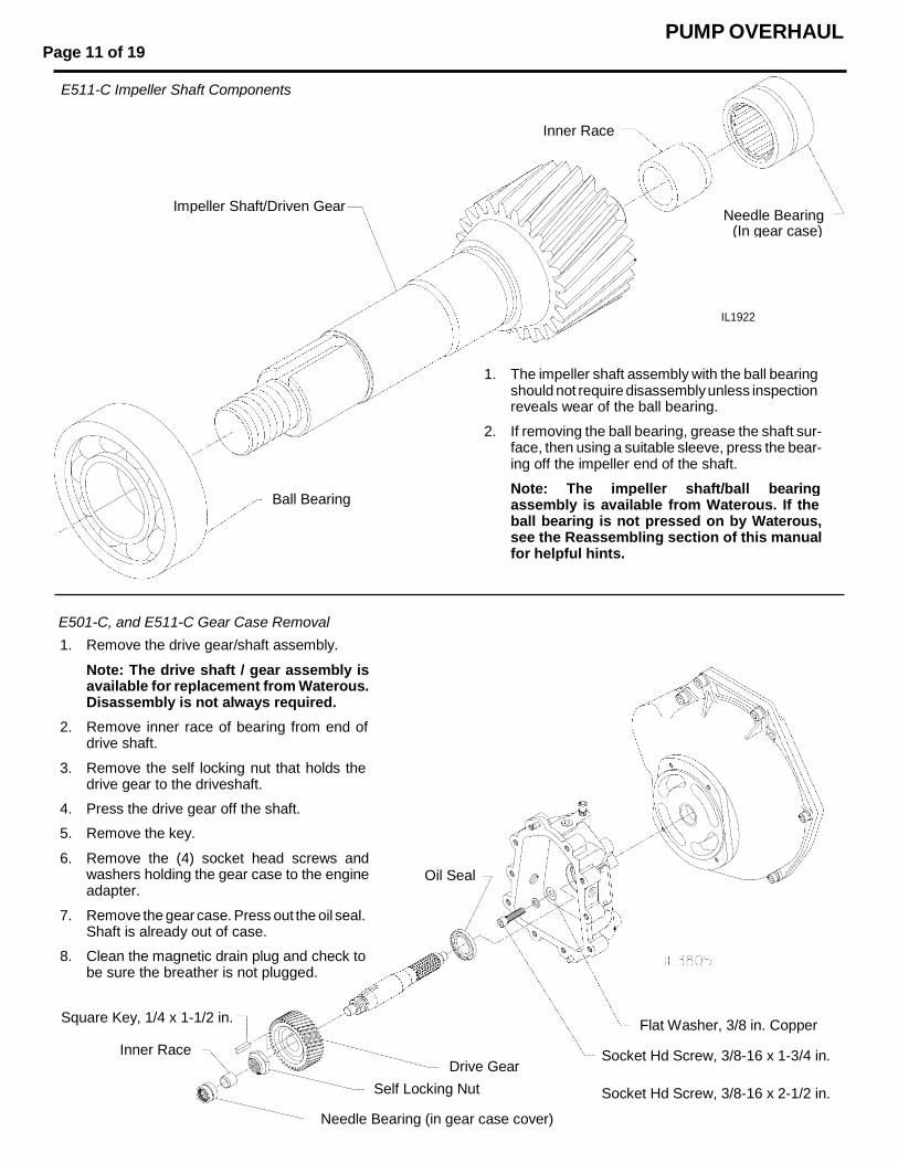
E501-C, and E511-C Gear Case Removal
1. Remove the drive gear/shaft assembly.
Note: The drive shaft / gear assembly is available for replacement from Waterous. Disassembly is not always required.
2. Remove inner race of bearing from end of drive shaft.
3. Remove the self locking nut that holds the drive gear to the driveshaft.
4. Press the drive gear off the shaft.
5. Remove the key.
6. Remove the (4) socket head screws and washers holding the gear case to the engine adapter.
7. Remove the gear case. Press out the oil seal. Shaft is already out of case.
8. Clean the magnetic drain plug and check to be sure the breather is not plugged.
Oil Seal
Square Key, 1/4 x 1-1/2 in.
Inner Race
Drive Gear
Self Locking Nut
Needle Bearing (in gear case cover)
Flat Washer, 3/8 in. Copper
Socket Hd Screw, 3/8-16 x 1-3/4 in.
Socket Hd Screw, 3/8-16 x 2-1/2 in.
E511-C Impeller Shaft Components
Inner Race
Impeller Shaft/Driven Gear Needle Bearing
(In gear case)
IL1922
1. The impeller shaft assembly with the ball bearing should not require disassembly unless inspection reveals wear of the ball bearing.
2. If removing the ball bearing, grease the shaft sur- face, then using a suitable sleeve, press the bear- ing off the impeller end of the shaft.
Ball Bearing Note: The impeller shaft/ball bearing assembly is available from Waterous. If the ball bearing is not pressed on by Waterous, see the Reassembling section of this manual for helpful hints.
PUMP OVERHAUL Page 12 of 19
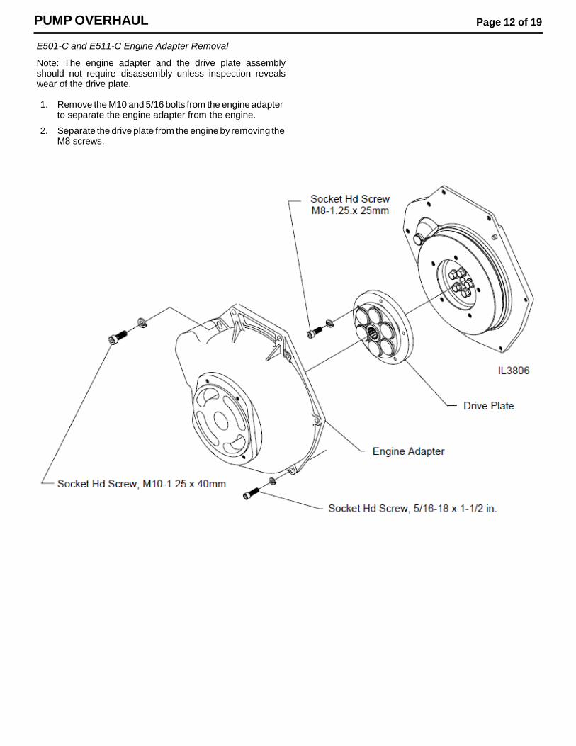
E501-C and E511-C Engine Adapter Removal
Note: The engine adapter and the drive plate assembly should not require disassembly unless inspection reveals wear of the drive plate.
1. Remove the M10 and 5/16 bolts from the engine adapter to separate the engine adapter from the engine.
2. Separate the drive plate from the engine by removing the M8 screws.
Page 13 of 19
CAUTION
Mechanical seal primary and stationary rings are made of brittle material. Material can be cracked or chipped. Extra care must be taken when handling these rings.
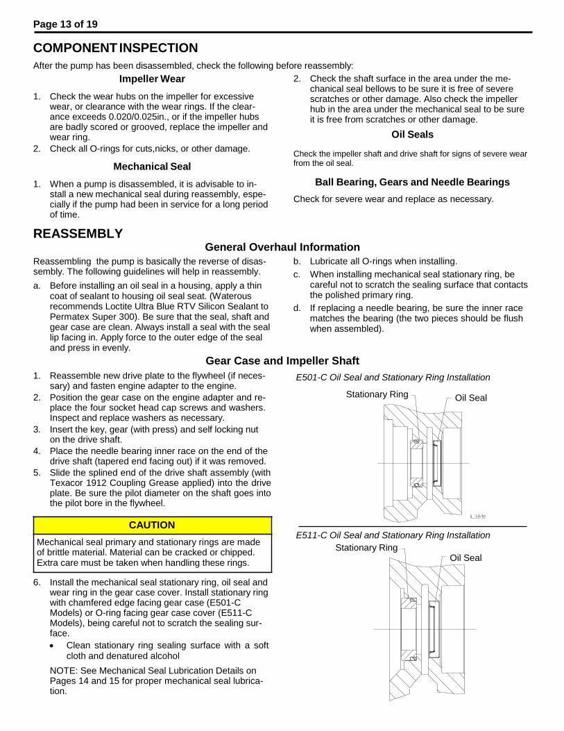
COMPONENT INSPECTION
After the pump has been disassembled, check the following before reassembly:
Impeller Wear
1. Check the wear hubs on the impeller for excessive wear, or clearance with the wear rings. If the clear- ance exceeds 0.020/0.025in., or if the impeller hubs are badly scored or grooved, replace the impeller and wear ring.
2. Check all O-rings for cuts,nicks, or other damage.
Mechanical Seal
1. When a pump is disassembled, it is advisable to in- stall a new mechanical seal during reassembly, espe- cially if the pump had been in service for a long period of time.
REASSEMBLY
2. Check the shaft surface in the area under the me- chanical seal bellows to be sure it is free of severe scratches or other damage. Also check the impeller hub in the area under the mechanical seal to be sure it is free from scratches or other damage.
Oil Seals
Check the impeller shaft and drive shaft for signs of severe wear from the oil seal.
Ball Bearing, Gears and Needle Bearings
Check for severe wear and replace as necessary.
General Overhaul Information
Reassembling the pump is basically the reverse of disas- sembly. The following guidelines will help in reassembly.
a. Before installing an oil seal in a housing, apply a thin coat of sealant to housing oil seal seat. (Waterous recommends Loctite Ultra Blue RTV Silicon Sealant to Permatex Super 300). Be sure that the seal, shaft and gear case are clean. Always install a seal with the seal lip facing in. Apply force to the outer edge of the seal and press in evenly.
b. Lubricate all O-rings when installing.
c. When installing mechanical seal stationary ring, be careful not to scratch the sealing surface that contacts the polished primary ring.
d. If replacing a needle bearing, be sure the inner race matches the bearing (the two pieces should be flush when assembled).
Gear Case and Impeller Shaft
1. Reassemble new drive plate to the flywheel (if neces- sary) and fasten engine adapter to the engine.
E501-C Oil Seal and Stationary Ring Installation
2. Position the gear case on the engine adapter and re- place the four socket head cap screws and washers. Inspect and replace washers as necessary.
3. Insert the key, gear (with press) and self locking nut on the drive shaft.
4. Place the needle bearing inner race on the end of the drive shaft (tapered end facing out) if it was removed.
5. Slide the splined end of the drive shaft assembly (with Texacor 1912 Coupling Grease applied) into the drive plate. Be sure the pilot diameter on the shaft goes into the pilot bore in the flywheel.
Stationary Ring Oil Seal
E511-C Oil Seal and Stationary Ring Installation
Stationary Ring Oil Seal
6. Install the mechanical seal stationary ring, oil seal and wear ring in the gear case cover. Install stationary ring with chamfered edge facing gear case (E501-C Models) or O-ring facing gear case cover (E511-C Models), being careful not to scratch the sealing sur- face.
Clean stationary ring sealing surface with a soft cloth and denatured alcohol
NOTE: See Mechanical Seal Lubrication Details on Pages 14 and 15 for proper mechanical seal lubrica- tion.
Page 14 of 19
Gear Case and Impeller Shaft (Continued)
7. Reassemble impeller shaft assembly if required.
Note: The impeller shaft/driven gear is nickel- plated on the surfaces susceptible to corrosion. If not careful when pressing on the ball bearing, this nickel plating can chip or peel.
The following are suggested methods of installing the ball bearing onto the impeller shaft:
a. Coat the inner diameter of the bearing and the bearing surface of the shaft with high pres- sure grease. Place the bearing on a flat sur- face and insert the shaft, square with the bear- ing, into the bearing. Press with a light force until the bearing and shaft have aligned prop- erly, then fully press on the bearing to the shoulder on the shaft.
b. Place the impeller shaft in a freezer until the shaft temperature stabilizes at 20_F or less.
Remove shaft from freezer, grease bearing surface of shaft and quickly place bearing onto shaft. The bearing should slide onto shaft freely or with a very light force, until
bearing rests against the shaft shoulder. Al- low shaft to sit for a few minutes at room tem- perature before installing in pump.
c. Warm the bearing with even heat, i.e. hot plate, to a temperature of 250-300_F (hot to the
touch). With the shaft surface greased, quickly place the bearing (handle with gloves or oven mitt) onto the shaft until it rests against the shaft shoulder. Allow bearing to cool until it can be handled without gloves.
Note: DO NOT use an open flame or microwave to heat bearing.
8. Insert the impeller shaft assembly in the gear case. Be sure the inner race is on the shaft end, tapered end facing out.
9. Using a new gasket, place the gear case cover on the gear case and replace the ten hex head screws and lock washers.
Note: It is very important to keep the mechanical seal sealing surfaces clean and scratch free. Any dirt, oil, or scoring can cause immediate failure or premature wear.
Primary Ring
Chamfered Edge Impeller Gasket
Stationary Ring
O-Ring
Bellows Assembly
Page 15 of 19
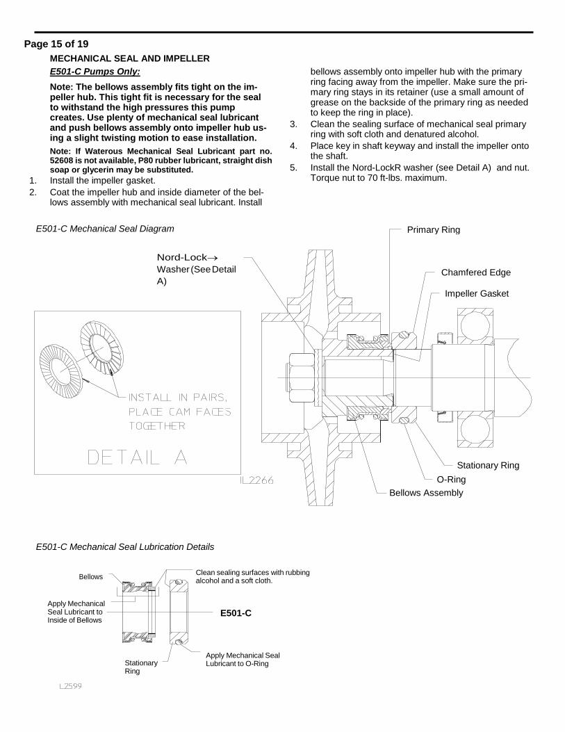
MECHANICAL SEAL AND IMPELLER
E501-C Pumps Only:
Note: The bellows assembly fits tight on the im- peller hub. This tight fit is necessary for the seal to withstand the high pressures this pump creates. Use plenty of mechanical seal lubricant and push bellows assembly onto impeller hub us- ing a slight twisting motion to ease installation.
Note: If Waterous Mechanical Seal Lubricant part no. 52608 is not available, P80 rubber lubricant, straight dish soap or glycerin may be substituted.
1. Install the impeller gasket.
2. Coat the impeller hub and inside diameter of the bel- lows assembly with mechanical seal lubricant. Install
bellows assembly onto impeller hub with the primary ring facing away from the impeller. Make sure the pri- mary ring stays in its retainer (use a small amount of grease on the backside of the primary ring as needed to keep the ring in place).
3. Clean the sealing surface of mechanical seal primary ring with soft cloth and denatured alcohol.
4. Place key in shaft keyway and install the impeller onto the shaft.
5. Install the Nord-LockR washer (see Detail A) and nut. Torque nut to 70 ft-lbs. maximum.
E501-C Mechanical Seal Diagram
Nord-Lock
Washer (See Detail
A)
E501-C Mechanical Seal Lubrication Details
Bellows Clean sealing surfaces with rubbing alcohol and a soft cloth.
Apply Mechanical Seal Lubricant to Inside of Bellows
E501-C
Stationary Ring
Apply Mechanical Seal Lubricant to O-Ring
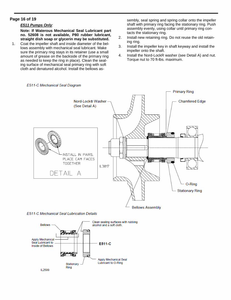
Page 16 of 19
E511 Pumps Only:
Note: If Waterous Mechanical Seal Lubricant part no. 52608 is not available, P80 rubber lubricant, straight dish soap or glycerin may be substituted.
1. Coat the impeller shaft and inside diameter of the bel- lows assembly with mechanical seal lubricant. Make sure the primary ring stays in its retainer (use a small amount of grease on the backside of the primary ring as needed to keep the ring in place). Clean the seal- ing surface of mechanical seal primary ring with soft cloth and denatured alcohol. Install the bellows as-
sembly, seal spring and spring collar onto the impeller shaft with primary ring facing the stationary ring. Push assembly evenly, using collar until primary ring con- tacts the stationary ring.
2. Install new retaining ring. Do not reuse the old retain- ing ring.
3. Install the impeller key in shaft keyway and install the impeller onto the shaft.
4. Install the Nord-LockR washer (see Detail A) and nut. Torque nut to 70 ft-lbs. maximum.
Page 17 of 19
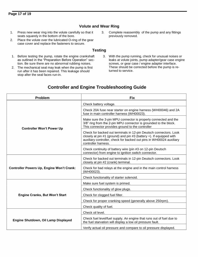
Volute and Wear Ring
1. Press new wear ring into the volute carefully so that it seats squarely in the bottom of the bore.
2. Place the volute over the lubricated O-ring of the gear case cover and replace the fasteners to secure.
3. Complete reassembly of the pump and any fittings previously removed.
Testing
1. Before testing the pump, rotate the engine crankshaft as outlined in the “Preparation Before Operation” sec- tion. Be sure there are no abnormal rubbing noises.
2. The mechanical seal may leak when the pump is first run after it has been repaired. This leakage should stop after the seal faces run-in.
3. With the pump running, check for unusual noises or leaks at volute joints, pump adapter/gear case engine screws, or gear case / engine adapter interface. These should be corrected before the pump is re- turned to service.
Controller and Engine Troubleshooting Guide
Problem Fix
Controller Won’t Power Up
Check battery voltage.
Check 20A fuse near starter on engine harness (WH00046) and 2A fuse in main controller harness (WH00023).
Make sure the 3-pin MPU connector is properly connected and the 3/8” ring from the 2-pin MPU connector is grounded to the block. This connector provides ground to the controller
Check for backed out terminals in 12-pin Deutsch connectors. Look closely at pin #1 (ground) and pin #3 (battery +). If equipped with auxiliary controller, check for backed out pins in WH00024 auxiliary controller harness.
Check continuity of battery wire (pin #3 on 12-pin Deutsch connector) from engine to ignition switch connector.
Controller Powers Up, Engine Won’t Crank:
Check for backed out terminals in 12-pin Deutsch connectors. Look closely at pin #2 (crank) terminal.
Check for bad relays at the engine and in the main control harness (WH00023).
Check functionality of starter solenoid.
Engine Cranks, But Won’t Start
Make sure fuel system is primed.
Check functionality of glow plugs.
Check for clogged fuel filter.
Check for proper cranking speed (generally above 250rpm).
Check quality of fuel.
Engine Shutdown, Oil Lamp Displayed
Check oil level.
Check fuel level/fuel supply. An engine that runs out of fuel due to the fuel starvation will display a low oil pressure fault.
Verify actual oil pressure and compare to oil pressure displayed.
Page 18 of 19
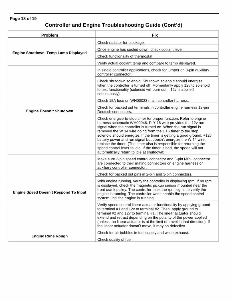
Controller and Engine Troubleshooting Guide (Cont’d)
Problem Fix
Engine Shutdown, Temp Lamp Displayed
Check radiator for blockage.
Once engine has cooled down, check coolant level.
Check functionality of thermostat.
Verify actual coolant temp and compare to temp displayed.
Engine Doesn’t Shutdown
In single controller applications, check for jumper on 8-pin auxiliary controller connector.
Check shutdown solenoid. Shutdown solenoid should energize when the controller is turned off. Momentarily apply 12v to solenoid to test functionality (solenoid will burn out if 12v is applied continuously).
Check 15A fuse on WH00023 main controller harness.
Check for backed out terminals in controller engine harness 12-pin Deutsch connectors.
Check energize-to-stop timer for proper function. Refer to engine harness schematic WH00046. R-Y 16 wire provides the 12v run signal when the controller is turned on. When the run signal is removed the W 14 wire going from the ETS timer to the stop solenoid should energize. If the timer is getting a good ground, +12v battery power and run signal but doesn’t energize the W 14 wire, replace the timer. (The timer also is responsible for returning the speed control lever to idle. If the timer is bad, the speed will not automatically return to idle at shutdown).
Engine Speed Doesn’t Respond To Input
Make sure 2-pin speed control connector and 3-pin MPU connector are connected to their mating connectors on engine harness or auxiliary controller connector.
Check for backed out pins in 2-pin and 3-pin connectors.
With engine running, verify the controller is displaying rpm. If no rpm is displayed, check the magnetic pickup sensor mounted near the front crank pulley. The controller uses the rpm signal to verify the engine is running. The controller won’t enable the speed control system until the engine is running.
Verify speed control linear actuator functionality by applying ground to terminal #1 and 12v to terminal #2. Then, apply ground to terminal #2 and 12v to terminal #1. The linear actuator should extend and retract depending on the polarity of the power applied (unless the linear actuator is at the limit of travel in that direction). If the linear actuator doesn’t move, it may be defective.
Engine Runs Rough Check for air bubbles in fuel supply and white exhaust.
Check quality of fuel.
Page 19 of 19
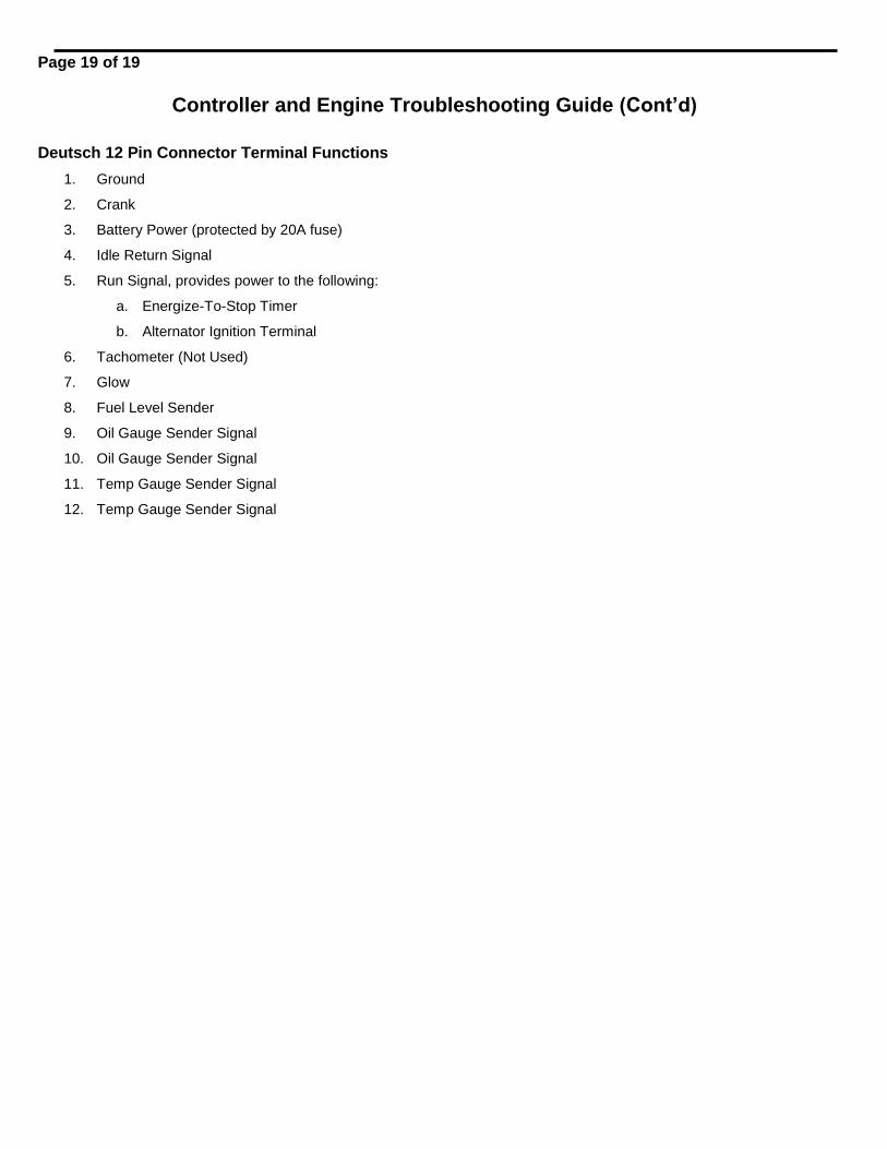
Controller and Engine Troubleshooting Guide (Cont’d)
Deutsch 12 Pin Connector Terminal Functions
1. Ground
2. Crank
3. Battery Power (protected by 20A fuse)
4. Idle Return Signal
5. Run Signal, provides power to the following:
a. Energize-To-Stop Timer
b. Alternator Ignition Terminal
6. Tachometer (Not Used)
7. Glow
8. Fuel Level Sender
9. Oil Gauge Sender Signal
10. Oil Gauge Sender Signal
11. Temp Gauge Sender Signal
12. Temp Gauge Sender Signal


![Compaq Armada E500 V300[1]](https://img.pdfslide.net/doc/110x75/577d1f4e1a28ab4e1e90511a/compaq-armada-e500-v3001.jpg)


![E500 Datasheet 20201111 [ENG]](https://img.pdfslide.net/doc/110x75/61f870f4db762243b65881d6/e500-datasheet-20201111-eng.jpg)


