Embed Size (px)
Citation preview

E5ZEMultipoint Temperature Controller
Operation Manual
Catalog No. H076-E3-1
!
!
!
v
Notice:OMRON products are manufactured for use according to proper procedures by a qualified operatorand only for the purposes described in this manual.
The following conventions are used to indicate and classify precautions in this manual. Always heedthe information provided with them. Failure to heed precautions can result in injury to people or dam-age to property.
DANGER Indicates an imminently hazardous situation which, if not avoided, will result in death orserious injury.
WARNING Indicates a potentially hazardous situation which, if not avoided, could result in death orserious injury.
Caution Indicates a potentially hazardous situation which, if not avoided, may result in minor ormoderate injury, or property damage.
OMRON Product ReferencesAll OMRON products are capitalized in this manual. The word “Unit” is also capitalized when it refersto an OMRON product, regardless of whether or not it appears in the proper name of the product.
The abbreviation “Ch,” which appears in some displays and on some OMRON products, often means“word” and is abbreviated “Wd” in documentation in this sense.
The abbreviation “PC” means Programmable Controller and is not used as an abbreviation for any-thing else.
Visual AidsThe following headings appear in the left column of the manual to help you locate different types ofinformation.
Note Indicates information of particular interest for efficient and convenient operationof the product.
1, 2, 3... 1. Indicates lists of one sort or another, such as procedures, checklists, etc.
OMRON, 1997All rights reserved. No part of this publication may be reproduced, stored in a retrieval system, or transmitted, in anyform, or by any means, mechanical, electronic, photocopying, recording, or otherwise, without the prior written permis-sion of OMRON.
No patent liability is assumed with respect to the use of the information contained herein. Moreover, because OMRON isconstantly striving to improve its high-quality products, the information contained in this manual is subject to changewithout notice. Every precaution has been taken in the preparation of this manual. Nevertheless, OMRON assumes noresponsibility for errors or omissions. Neither is any liability assumed for damages resulting from the use of the informa-tion contained in this publication.

TABLE OF CONTENTS
vii
PRECAUTIONS xi. . . . . . . . . . . . . . . . . . . . . . . . . . . . . . . . . 1 General Safety Precautions xii. . . . . . . . . . . . . . . . . . . . . . . . . . . . . . . . . . . . . . . . . . . . . . . . . . . . 2 Operating Environment Precautions xii. . . . . . . . . . . . . . . . . . . . . . . . . . . . . . . . . . . . . . . . . . . . . 3 Application Precautions xii. . . . . . . . . . . . . . . . . . . . . . . . . . . . . . . . . . . . . . . . . . . . . . . . . . . . . .
SECTION 1Introduction 1. . . . . . . . . . . . . . . . . . . . . . . . . . . . . . . . . . . .
1-1 Component Names and Functions 2. . . . . . . . . . . . . . . . . . . . . . . . . . . . . . . . . . . . . . . . . . . 1-2 System Configuration 4. . . . . . . . . . . . . . . . . . . . . . . . . . . . . . . . . . . . . . . . . . . . . . . . . . . . . 1-3 Main Functions 5. . . . . . . . . . . . . . . . . . . . . . . . . . . . . . . . . . . . . . . . . . . . . . . . . . . . . . . . . .
SECTION 2Preparations 7. . . . . . . . . . . . . . . . . . . . . . . . . . . . . . . . . . . .
2-1 List of Models 8. . . . . . . . . . . . . . . . . . . . . . . . . . . . . . . . . . . . . . . . . . . . . . . . . . . . . . . . . . 2-2 Mounting the Serial Communications Models 10. . . . . . . . . . . . . . . . . . . . . . . . . . . . . . . . . 2-3 Setting Selectors and Switch 12. . . . . . . . . . . . . . . . . . . . . . . . . . . . . . . . . . . . . . . . . . . . . . . 2-4 Installation 15. . . . . . . . . . . . . . . . . . . . . . . . . . . . . . . . . . . . . . . . . . . . . . . . . . . . . . . . . . . . . 2-5 Power Supply and Input Wiring 17. . . . . . . . . . . . . . . . . . . . . . . . . . . . . . . . . . . . . . . . . . . . . 2-6 Wiring CT Inputs and Control/Alarm Outputs 19. . . . . . . . . . . . . . . . . . . . . . . . . . . . . . . . . 2-7 Connecting Communications 24. . . . . . . . . . . . . . . . . . . . . . . . . . . . . . . . . . . . . . . . . . . . . . .
SECTION 3Functions 29. . . . . . . . . . . . . . . . . . . . . . . . . . . . . . . . . . . . . .
3-1 Data Configuration 30. . . . . . . . . . . . . . . . . . . . . . . . . . . . . . . . . . . . . . . . . . . . . . . . . . . . . . . 3-2 I/O Settings 31. . . . . . . . . . . . . . . . . . . . . . . . . . . . . . . . . . . . . . . . . . . . . . . . . . . . . . . . . . . . . 3-3 Set Point and Process Value 32. . . . . . . . . . . . . . . . . . . . . . . . . . . . . . . . . . . . . . . . . . . . . . . . 3-4 Alarm Output Settings 33. . . . . . . . . . . . . . . . . . . . . . . . . . . . . . . . . . . . . . . . . . . . . . . . . . . . 3-5 Output Limitations 35. . . . . . . . . . . . . . . . . . . . . . . . . . . . . . . . . . . . . . . . . . . . . . . . . . . . . . . 3-6 Ramp 36. . . . . . . . . . . . . . . . . . . . . . . . . . . . . . . . . . . . . . . . . . . . . . . . . . . . . . . . . . . . . . . . . 3-7 Control Adjustments 37. . . . . . . . . . . . . . . . . . . . . . . . . . . . . . . . . . . . . . . . . . . . . . . . . . . . . 3-8 Control Method Selection 39. . . . . . . . . . . . . . . . . . . . . . . . . . . . . . . . . . . . . . . . . . . . . . . . . 3-9 Heating and Cooling Control 41. . . . . . . . . . . . . . . . . . . . . . . . . . . . . . . . . . . . . . . . . . . . . . . 3-10 Heater Burnout Detection 42. . . . . . . . . . . . . . . . . . . . . . . . . . . . . . . . . . . . . . . . . . . . . . . . . 3-11 SSR Failure Detection 44. . . . . . . . . . . . . . . . . . . . . . . . . . . . . . . . . . . . . . . . . . . . . . . . . . . .
SECTION 4Troubleshooting 47. . . . . . . . . . . . . . . . . . . . . . . . . . . . . . . . .
4-1 Troubleshooting Procedure 48. . . . . . . . . . . . . . . . . . . . . . . . . . . . . . . . . . . . . . . . . . . . . . . . 4-2 Communications Errors 49. . . . . . . . . . . . . . . . . . . . . . . . . . . . . . . . . . . . . . . . . . . . . . . . . . . 4-3 Temperature Sensing Errors 51. . . . . . . . . . . . . . . . . . . . . . . . . . . . . . . . . . . . . . . . . . . . . . . . 4-4 Temperature Control Errors 53. . . . . . . . . . . . . . . . . . . . . . . . . . . . . . . . . . . . . . . . . . . . . . . . 4-5 Output Errors 55. . . . . . . . . . . . . . . . . . . . . . . . . . . . . . . . . . . . . . . . . . . . . . . . . . . . . . . . . . . 4-6 HB Alarm and HS Alarm Errors 57. . . . . . . . . . . . . . . . . . . . . . . . . . . . . . . . . . . . . . . . . . . .
AppendicesA Specifications 59. . . . . . . . . . . . . . . . . . . . . . . . . . . . . . . . . . . . . . . . . . . . . . . . . . . . . . . . . . . . . . B Current Transformer Specifications 65. . . . . . . . . . . . . . . . . . . . . . . . . . . . . . . . . . . . . . . . . . . . . C Manually Setting PID Constants 67. . . . . . . . . . . . . . . . . . . . . . . . . . . . . . . . . . . . . . . . . . . . . . . D Saving Data 71. . . . . . . . . . . . . . . . . . . . . . . . . . . . . . . . . . . . . . . . . . . . . . . . . . . . . . . . . . . . . . . E Hardware Test 73. . . . . . . . . . . . . . . . . . . . . . . . . . . . . . . . . . . . . . . . . . . . . . . . . . . . . . . . . . . . . F Available Models 79. . . . . . . . . . . . . . . . . . . . . . . . . . . . . . . . . . . . . . . . . . . . . . . . . . . . . . . . . . .
Revision History 81. . . . . . . . . . . . . . . . . . . . . . . . . . . . . . . . .

ix
About this Manual:
This manual describes the installation and operation of E5ZE Multipoint Temperature Controllers andincludes the sections described below.
Refer to the following manuals according to the model being used before operating the E5ZE.
Refer to the following manual when using the E5ZE Serial Communications Models:
E5ZE Multipoint Temperature Controller Communications Manual (Cat. No. H77)
Refer to the following manual when using the DeviceNet Communications Models:
E5ZE-8 Multipoint Temperature Controller DeviceNet Communications Manual (Cat. No. H104)
DeviceNet Operation Manual (Cat. No. W267)
Please read this manual carefully and be sure you understand the information provided before at-tempting to install or operate an E5ZE Multipoint Temperature Controller. Be sure to read the Precautions section.
Precautions provides precautions for installing and using the E5ZE.
Section 1 provides information on the system configuration, component names, and functions.
Section 2 describes the installation and wiring procedures necessary before operating the E5ZE.
Section 3 describes each of the E5ZE functions.
Section 4 describes the troubleshooting procedure for the E5ZE.
The Appendices provide information on specifications, ratings, characteristics, the Current Trans-former, PID constant manual adjustments, saving data, hardware tests, current outputs, and availablemodels.
WARNING Failure to read and understand the information provided in this manual may result inpersonal injury or death, damage to the product, or product failure. Please read eachsection in its entirety and be sure you understand the information provided in the sectionand related sections before attempting any of the procedures or operations given.
!

xi
PRECAUTIONS
This section provides general precautions for using the E5ZE Multipoint Temperature Controller and related devices.
The information contained in this section is important for the safe and reliable application of the E5ZE MultipointTemperature Controller. You must read this section and understand the information contained before attempting toset up or operate an E5ZE Multipoint Temperature Controller.
1 General Safety Precautions xii. . . . . . . . . . . . . . . . . . . . . . . . . . . . . . . . . . . . . . . . . . . . . . . . . . . . . 2 Operating Environment Precautions xii. . . . . . . . . . . . . . . . . . . . . . . . . . . . . . . . . . . . . . . . . . . . . . 3 Application Precautions xii. . . . . . . . . . . . . . . . . . . . . . . . . . . . . . . . . . . . . . . . . . . . . . . . . . . . . . . .

!
!
!
!
!
!
!
!
!
!
3Application Precautions
xii
1 General Safety Precautions
WARNING Do not attempt to disassemble, apply pressure, distort, subject to temperaturesof 100°C or more, or throw the E5ZE into fire. A lithium battery is built into theE5ZE and any attempt to any of the above may result in fire, explosion, orcombustion.
WARNING Do not attempt to disassemble, modify, or repair the E5ZE. Any attempt to do somay result in malfunction, fire, or electric shock.
Caution Do not use any terminal that is marked “Don’t use.”
2 Operating Environment Precautions
Caution Be sure to check polarity when connecting the terminals.
Caution Do not install power lines or high-tension lines alongside lines connected to theE5ZE to prevent the E5ZE from being influenced by inductive noise. Install linesconnected to the E5ZE through an independent conduit or use a shielded cablefor the lines to protect them from inductive noise.
Caution Separate the E5ZE from devices generating a strong high-frequency, such ashigh-frequency welding machines, or devices that generate surge.
Caution Do not operate the E5ZE in the following locations:
• Locations subject to exposure to water, oil, or chemicals.
• Locations subject to corrosive or flammable gases.
• Locations subject to temperatures or humidity outside the range specified inthe specifications.
• Locations subject to condensation.
• Locations subject to shock or vibration.
• Locations subject to severe changes in temperature.
• Locations subject to icing.
Caution Do not install the E5ZE in a location with obstructions preventing radiant heatfrom escaping.
3 Application Precautions
WARNING Make sure that no metal particles or wire chips are accidentally left in theproduct. Doing so may result in malfunction, fire, or electric shock.
WARNING Install a separate alarm to prevent the temperature from increasing excessivelyif the E5ZE malfunctions. Insufficient safety precautions may cause seriousaccidents if the temperature control malfunctions.
!
!
!
!
!
3Application Precautions
xiii
Caution Tighten the screws on the terminal block to the torque specified in the manual.Loose screws may result in burning or malfunction.
Caution Do not connect loads to the E5ZE that exceed the specified ratings. Excessivelylarge loads may result in malfunction or burning.
Caution Always use the power supply voltage specified in the manual. An incorrect volt-age may result in malfunction or burning.
Caution Confirm that no adverse effects will occur in the system before attempting to per-form a hardware test. Insufficient confirmation may result in unexpected opera-tions.
Caution Make sure that all the E5ZE set values are suitable for the controlled system.Unsuitable set values may result in unexpected operations causing damage tothe product or accidents.

1
SECTION 1Introduction
This section describes the components, a standard system configuration, and the functions of the E5ZE. Refer to Section 2Preparations and later sections for details on functions and their applications.
1-1 Component Names and Functions 2. . . . . . . . . . . . . . . . . . . . . . . . . . . . . . . . . . . . . . . . . . . . 1-2 System Configuration 4. . . . . . . . . . . . . . . . . . . . . . . . . . . . . . . . . . . . . . . . . . . . . . . . . . . . . . 1-3 Main Functions 5. . . . . . . . . . . . . . . . . . . . . . . . . . . . . . . . . . . . . . . . . . . . . . . . . . . . . . . . . . .

2
1-1 Component Names and FunctionsThe component names and their functions are provided here.
Indicators
Setting selectors and switch
Input terminal block
Communicationsconnector
CT INPUTconnector
CONTROLconnector
ALARM connector
Indicators
A: E5ZE-8AB (Standard Models with casing)
V: E5ZE-8VB (Heating and Cooling Control Models with casing)
The indicators show the operating status of the E5ZE, as follows:
PWR: Lit when power is ON.
RDY: Lit when the E5ZE is ready to operate.
ERR: Lit when an error occurs in the E5ZE.
RUN: Lit when the E5ZE is operating.
AT: Lit when auto-tuning is being executed.
RD: Lit when the E5ZE is receiving command data.
SD: Lit when the E5ZE is sending response data.
CH0 to CH7:Lit for the control points for which the corresponding control outputs are ON. (Not lit for Current Output Models.)
H0 to H7:Lit for the control points for which the corresponding heating outputs are ON.(Not lit for Current Output Models.)
C0 to C7:Lit for the control points for which the corresponding cooling outputs are ON.
AL1: Lit when alarm 1 is ON.
AL2: Lit when alarm 2 is ON.
HB: Lit when the HB (heater burnout) alarm is ON.
HS: Lit when the HS alarm (SSR short circuit) is ON.
MB0 to MB2:Lit when the memory bank designation inputs (bits 20 to 22) are turned ON withexternal contacts.
Indicators
Component Names and Functions Section 1-1

3
The setting selectors and switch are used to select the temperature sensor type,the unit number, and the functions to be used with the E5ZE. Refer to 2-3 SettingSelectors and Switch for details on setting methods.
The input terminal block is connected to a DC power supply, temperature sen-sor, and ground wire. Refer to 2-5 Power Supply and Input Wiring for details onwiring procedures.
The communications connector is connected to the communications cable. Re-fer to the E5ZE Multipoint Temperature Controller Communications Manual(H77) or the E5ZE-8 Multipoint Temperature Controller DeviceNet Communica-tions Manual (H104) for details on communications functions and their applica-tions.
E5ZE-8D1B
(for DeviceNet communications)
E53-E01
(for RS-232CCommunicationsUnit)
E53-E04
(for RS-422/485CommunicationsUnit)
The CT INPUT connector is connected to the Current Transformer (CT) to detectheater burnout or SSR failure. Use E5ZE-CBL Connecting Cables to con-nect to the Connector Terminal Conversion Unit (XW2B-20G5 for M3.5 terminalscrews or XW2B-20G4 for M2.4 terminal screws). Refer to 2-6 Wiring CT Inputsand Control/Alarm Outputs for details on wiring procedures.
The CONTROL connector is used to connect the control output and memorybank designation input contacts. Use E5ZE-CBL Connecting Cables toconnect to the Connector Terminal Conversion Unit (XW2B-20G5 for M3.5 ter-minal screws or XW2B-20G4 for M2.4 terminal screws). Refer to 2-6 Wiring CTInputs and Control/Alarm Outputs for details on wiring procedures.
The ALARM connector for the E5ZE-8A Standard Models is used foran alarm output and that for the E5ZE-8V Heating and Cooling Con-trol Models is used for cooling control output and alarm output. Use E5ZE-CBL- Connecting Cables to connect to the following devices.
Device Model Specifications and CommentsConnector Terminal XW2B-20G4 M2.4 terminal screwsConversion Units XW2B-20G5 M3.5 terminal screws
I/O Relay Terminal G7TC-OC08 8 relay outputs (no cooling outputs)
G7TC-OC16 16 relay outputs Cooling outputs
I/O Relay Terminal G7VC-OC16 16 relay outputs terminal is not
G7VC-OA16 16 SSR ACoutputs
available on thestandard model.
G7VC-OD16 16 SSR DCoutputs
Setting Selectors andSwitch
Input Terminal Block
CommunicationsConnector
CT INPUT Connector
CONTROL Connector
ALARM Connector
Component Names and Functions Section 1-1

4
1-2 System ConfigurationThe following diagram shows the system configuration of the E5ZE.
Control outputsMemorybank desig-nation inputs
24-VDC powersupply
Platinumresistance thermometer orthermocouple
Communications interface:RS-232C, RS-422 orRS-485, or DeviceNet
Host deviceComputerProgrammable ControllerE5ZD-SDL SettingDisplay Unit
CurrentTrans-former(CT)
Coolingcontrol outputsAlarm outputs
Inputterminalblock
Commu-
nications
connector
CT INPUT
connector
CONTROL
connector
ALARM
connector
E5ZE-CBL
Connecting Cables
XW2B-20G5/4Connector TerminalConversion Unit
XW2B-20G5/4Connector TerminalConversion Unit
XW2B-20G5/4Connector TerminalConversion Unit/I/O Blocks
E5ZE
Use the specified cables and wiring devices to prevent malfunctions or acci-dents caused by incorrect wiring.
• The connection between the communications connector and the host devicediffers according to the communications interface used. Refer to the E5ZEMultipoint Temperature Controller Communications Manual (H77) or theE5ZE-8 Multipoint Temperature Controller DeviceNet Communications Manu-al (H104) for details.
• There are restrictions on the items that can be set or displayed from the E5ZD-SDL Setting Display Unit. Refer to the E5ZD-SDL Setting Display Unit Data-sheet (H61) for details.
System Configuration Section 1-2

5
Isolation
DeviceNet
E5ZE
Powersupply
RS-232C
RS-422
RS-485
Inputterminalblock
CT INPUTconnector
CONTROLconnector
ALARMconnector
FG
The components of the E5ZE contained within bold lines in the above diagramare electrically isolated.
Note The covers of the CT INPUT, CONTROL, and ALARM connectors are con-nected to the frame ground (FG).
For the E5ZE-8TC (Thermocouple Input Models), the thermocoupleinputs of the control points are insolated from each other.
1-3 Main FunctionsThe E5ZE is connected to platinum resistance thermometers or thermocouples,depending on the model used. The type of temperature sensor is specified usingthe INPUT selector on the front panel of the Unit. The input values can be ad-justed using the input adjustment function.
The control outputs can be either voltage output or current output, depending onthe model. The control period and direct/reverse operation can be specified us-ing the set values.
A maximum of 2 alarm outputs are possible. There are 12 alarm modes that canbe set for each alarm output according to set values. The outputs are compre-hensive output for all control points.
The output values are limited by the following 2 limiters:• Output limiter• Output change rate limiterIf an output value is outside the upper or lower limit for the output, the output willbe limited to the preset upper or lower limit. The output change rate limiter limitsthe rate at which output values change per unit time.
The ramp function is used to limit the control temperature (set point) from chang-ing rapidly. If the set point changes quicker than the preset rate, the rate of tem-perature change will be limited to the preset rate, and the temperature will gradu-ally change until it reaches the new temperature. The ramp can be set by theuser.
Input Type
CONTROL Outputs
ALARM Outputs
Output Limitations
Ramp
Main Functions Section 1-3

6
PID and fuzzy constants can be set by executing auto-tuning (AT). If an offsetoccurs during P or PD control, manual adjustment is possible using the manualreset function. Temperature turbulence caused by external disturbances can besuppressed and controlled using the fuzzy function.
Output short circuits caused by heater burnout or SSR failure can be detected.
Control can be switched between ON/OFF control and the normal 2-PID control(with 2 degrees of freedom). Manual operation is also possible.
The memory banks store different sets of set values for the control points. Thereare 8 memory banks for each control point. Memory banks allow the set valuesfor a control point to be changed as a group rather than resetting them individu-ally. Use the external contact inputs or communications to designate the re-quired memory bank.
Control Adjustment
Heater Burnout and SSRFailure Detection
Control Method Selection
Memory Banks
Main Functions Section 1-3
7
SECTION 2Preparations
This section provides details on operations that must be performed before starting the E5ZE, such as installation and wiring.
2-1 List of Models 8. . . . . . . . . . . . . . . . . . . . . . . . . . . . . . . . . . . . . . . . . . . . . . . . . . . . . . . . . . . 2-1-1 Serial Communications Models 8. . . . . . . . . . . . . . . . . . . . . . . . . . . . . . . . . . . . . . . 2-1-2 DeviceNet Communications Models 9. . . . . . . . . . . . . . . . . . . . . . . . . . . . . . . . . . .
2-2 Mounting the Serial Communications Models 10. . . . . . . . . . . . . . . . . . . . . . . . . . . . . . . . . . . 2-3 Setting Selectors and Switch 12. . . . . . . . . . . . . . . . . . . . . . . . . . . . . . . . . . . . . . . . . . . . . . . .
2-3-1 UNIT Selector 12. . . . . . . . . . . . . . . . . . . . . . . . . . . . . . . . . . . . . . . . . . . . . . . . . . . . 2-3-2 INPUT Selector 12. . . . . . . . . . . . . . . . . . . . . . . . . . . . . . . . . . . . . . . . . . . . . . . . . . . 2-3-3 FUNCTION Switch 13. . . . . . . . . . . . . . . . . . . . . . . . . . . . . . . . . . . . . . . . . . . . . . . .
2-4 Installation 15. . . . . . . . . . . . . . . . . . . . . . . . . . . . . . . . . . . . . . . . . . . . . . . . . . . . . . . . . . . . . . 2-4-1 External and Panel Dimensions 15. . . . . . . . . . . . . . . . . . . . . . . . . . . . . . . . . . . . . . . 2-4-2 Mounting 16. . . . . . . . . . . . . . . . . . . . . . . . . . . . . . . . . . . . . . . . . . . . . . . . . . . . . . . .
2-5 Power Supply and Input Wiring 17. . . . . . . . . . . . . . . . . . . . . . . . . . . . . . . . . . . . . . . . . . . . . . 2-5-1 Terminal Block 17. . . . . . . . . . . . . . . . . . . . . . . . . . . . . . . . . . . . . . . . . . . . . . . . . . . 2-5-2 Wiring 17. . . . . . . . . . . . . . . . . . . . . . . . . . . . . . . . . . . . . . . . . . . . . . . . . . . . . . . . . . 2-5-3 Terminal Arrangement 18. . . . . . . . . . . . . . . . . . . . . . . . . . . . . . . . . . . . . . . . . . . . . . 2-5-4 Power Supply 18. . . . . . . . . . . . . . . . . . . . . . . . . . . . . . . . . . . . . . . . . . . . . . . . . . . . . 2-5-5 Ground 18. . . . . . . . . . . . . . . . . . . . . . . . . . . . . . . . . . . . . . . . . . . . . . . . . . . . . . . . . . 2-5-6 Thermocouple Input 19. . . . . . . . . . . . . . . . . . . . . . . . . . . . . . . . . . . . . . . . . . . . . . . . 2-5-7 Platinum Resistance Thermometer Input 19. . . . . . . . . . . . . . . . . . . . . . . . . . . . . . . .
2-6 Wiring CT Inputs and Control/Alarm Outputs 19. . . . . . . . . . . . . . . . . . . . . . . . . . . . . . . . . . . 2-6-1 CT Inputs 20. . . . . . . . . . . . . . . . . . . . . . . . . . . . . . . . . . . . . . . . . . . . . . . . . . . . . . . . 2-6-2 Outputs 21. . . . . . . . . . . . . . . . . . . . . . . . . . . . . . . . . . . . . . . . . . . . . . . . . . . . . . . . . .
2-7 Connecting Communications 24. . . . . . . . . . . . . . . . . . . . . . . . . . . . . . . . . . . . . . . . . . . . . . . . 2-7-1 RS-232C 24. . . . . . . . . . . . . . . . . . . . . . . . . . . . . . . . . . . . . . . . . . . . . . . . . . . . . . . . . 2-7-2 RS-422 and RS-485 25. . . . . . . . . . . . . . . . . . . . . . . . . . . . . . . . . . . . . . . . . . . . . . . . 2-7-3 DeviceNet Interface 27. . . . . . . . . . . . . . . . . . . . . . . . . . . . . . . . . . . . . . . . . . . . . . . .

2-1SectionList of Models
8
2-1 List of Models
2-1-1 Serial Communications ModelsNo. ofcontrol
Casing Controlmethod
Controloutput
Heaterburnout and
Commu-nications
Input type
points SSR failuredetection
Thermocouple Platinumresistance
thermometer
8 Yes Standard Option Option Option E5ZE-8AAAMTCB-E E5ZE-8AAAMPB-E
Heatingandcooling
Option Option Option E5ZE-8VAAMTCB-E E5ZE-8VAAMPB-E
Model Number Legend:
E5ZE-8AAM-E1 2 3 4 5 6 7
1. Control Point8: 8
2. Control MethodA: Standard
V: Heating and cooling
3. Control OutputA: Option (see note 1)
4. Heater Burnout and SSR Failure Detection (see note 2)A: Option (see note 3)
5. CommunicationsM: Option (see note 4)
6. Input TypeTC: Thermocouple
P: Platinum resistance thermometer
7. CasingB: Yes
Note: 1. The E53-E8Q Voltage Output Unit or the E53-E8CCurrent Output Unit can be used with the E5ZE. TheE53-E8Q Voltage Output Unit and the E53-E8C Current Output Unit are sold separately.
2. The heater burnout and SSR failure detection function of the E5ZE will be invalid if the heating sidecontrol output of the E5ZE is current output.
3. The E54-E8CT CT Input Unit is required for the heater burnout and SSR failure detection. TheE54-E8CT CT Input Unit is sold separately.
4. The E53-E01 Communications Unit for RS-232Ccommunication or the E53-E04 Communications Unitfor RS-422 and RS-485 communication can be usedwith the E5ZE. The E53-E01 Communications Unitand the E53-E04 Communications Unit are sold separately.
Units Models
RS-232C Communications Unit E53-E01
RS-422/485 Communications Unit E53-E04
CT Input Unit E54-E8CT
Voltage Output Unit E53-E8Q
Current Output Unit E53-E8C
I/O Units (Order Separately)

2-1SectionList of Models
9
2-1-2 DeviceNet Communications ModelsNo of control
pointsCasing Control
methodControloutput
HBA and SSRfailure
detection
Iput type Name
8 Yes Standard Voltage Yes Thermocouple E5ZE-8AQHD1TCB24VDC
8 Yes Standard Voltage Yes Platinumresistancethermometer
E5ZE-8AQHD1PB 24VDC
8 Yes Standard Current No Thermocouple E5ZE-8ACAD1TCB24VDC
8 Yes Standard Current No Platinumresistancethermometer
E5ZE-8ACAD1PB 24VDC
8 Yes Heating andCooling
Voltage Yes Thermocouple E5ZE-8VQHD1TCB24VDC
8 Yes Heating andCooling
Voltage Yes Platinumresistancethermometer
E5ZE-8VQHD1PB 24VDC
8 Yes Heating andCooling
Current No Thermocouple E5ZE-8VCAD1TCB24VDC
8 Yes Heating andCooling
Current No Platinumresistancethermometer
E5ZE-8VCAD1PB 24VDC
Model Number Legend:
E5ZE-8
1 2 3 4 5 6 7
1. Control Point
8: 8
2. Control Method
A: Standard control
V: Heating and cooling control
3. Control Output
Q: Voltage output
C: Current output
4. Heater Burnout and SSR Failure Detection Function(Not available with Current Output Models.)A: No
H: Yes
5. Communications FunctionD1: DeviceNet
6. Input TypeTC: Thermocouple
P: Platinum resistance thermometer
7. CasingB: Yes

2-2SectionMounting the Serial Communications Models
10
2-2 Mounting the Serial Communications ModelsI/O Units are not mounted on the E5ZE.
Mount the appropriate I/O Units according to the specification of the E5ZE.
The diagram below is the view from the back of component side.
Type of I/O Units
Communication Unit
CT Input Unit
Output Unit
E53-E01 forRS-232C
E53-E04 forRS-422/RS-485
E54-E8CT
E53-E8Q for voltageoutput
E53-E8C for currentoutput
or
Use this CT input unit in combinationwith the E53-E8Q voltage output unit.
or
Tighten the screws through the holes marked with a black dot () to the fixingstuds of the E5ZE.
Mounting Position of I/O Units
Communication Unit
CT Input Unit
Output Unit
Connector
CommunicationUnit
CT Input Unit
Connector
Output Unit
Connector
Remove this screw when the Unit ismounted on the model with casing.
I/O Units

2-2SectionMounting the Serial Communications Models
11
Use appropriate Phillips screwdriver for the screws. Use of an inappropriatescrewdriver may damage the screws and cause insufficient tightening.
Mount the Units in an environment where anti-static electricity countermeasureshave been taken.
Store the removed screws carefully and use them again when required.
Model With Casing
1, 2, 3... 1. Remove the connector fixing screws (2 screws each for a connector) fromthe Units (except for communication unit).
2. Remove the casing fixing screws (6 screws).
3. Remove the casing.
4. Mount the Units in the same manner as the model without casing.
5. Fix the connector to the case using the connector fixing screws with a torqueof 0.34 to 0.39 Nm.
6. Replace the casing in its original position using six casing fixing screws.
Casing securing
Case
Casing
Remove the casing after removingthe casing fixing screws(6 pcs.)
Casing securing
Identification label forconnector
CT INPUTCONTROLALARM
Fixing studs for the Units
Communication Unit : 3 pcs.CT Input Unit : 3 pcs.Output Unit : 4 pcs.
The Unit fixing screws aremounted on the fixing studs atthe factory.
Communication Unit(sold separately)E53-E01 or E53-E04(The diagram showsE53-E04)
CT Input Unit(sold separately )E54-E8CT
Output Unit (sold separately)E53-E8Q or E53-E8C
Mounting the Units

2-3SectionSetting Selectors and Switch
12
2-3 Setting Selectors and SwitchObserve the following precautions when operating the selectors and switch.
• Always make sure the power is OFF before changing the selectors and switch.
• Use a small flat-blade screwdriver to change the selector and switch settings,and be sure that the selectors are correctly positioned.
2-3-1 UNIT Selector
UNIT INPUT
When serial communications are being used, the UNIT selector must be set sothat the host device can recognize the E5ZE unit number.
When more than one E5ZE Multipoint Temperature Controller is being used withRS-422 or RS-485 communications, set a different unit number for each E5ZE.
• The selector settings 0 to F correspond to unit numbers 00 to 0F. The factorysetting of 0 corresponds to unit number 00.
2-3-2 INPUT Selector
UNIT INPUT
Set the INPUT selector according to the type of temperature sensor connectedto the E5ZE. The selector positions and corresponding temperature sensors areas follows:
Selectorsetting
0 1 2 3 4 5 6 7 8 9 A B C D E F
Thermocouple K J R S T E B N L U W PLII Not used.
Platinumresistancethermometer
Pt JPt Not used.
• The factory setting is 0.
• The platinum resistance thermometer settings “Pt” and “JPt” indicate Pt100and JPt100 respectively.

2-3SectionSetting Selectors and Switch
13
2-3-3 FUNCTION SwitchThe FUNCTION switch is used to set the parameters of the E5ZE, such as thebaud rate and startup operation.
FUNCTION
Operation mode change
Not used. (Always set to OFF.)
Temperature unit (°C or °F)
Startup operation
E5ZD-SDL Setting Display Unit connection
Memory bank designation method
Baud rate (serial communications)
Set the baud rate using pins 1 and 2 to the baud rate of the host device con-nected to the EZ5E.
Baud rate 19,200 bps 9,600 bps 4,800 bps 2,400 bps
Pin 1
Pin 2
The factory setting is 9,600 bps (pin 1 ON, pin 2 OFF).
Pin 3 is used to set the memory bank designation method.
Memory bankdesignation
Communications Contact inputs
Pin 3
The factory setting is for communications (pin 3 OFF).When contact inputs are used to switch memory banks, the specified memorybank will be used for all control points.
Pin 4 is used to specify when an E5ZD-SDL Setting Display Unit is connected.
E5ZD-SDL connection Not connected Connected
Pin 4
The factory setting is for no connection (pin 4 OFF). Set pin 4 to ON when anE5ZD-SDL Setting Display Unit is to be connected to the E5ZE.
Baud Rate (SerialCommunications)
Memory Bank DesignationMethod
E5ZD-SDL Setting DisplayUnit Connection

2-3SectionSetting Selectors and Switch
14
Pin 5 is used to set the startup operation.
Startup operation Stop operation control Continue status atpower OFF
Pin 5
The factory setting is for stop operation control (pin 5 OFF).
If the power is turned OFF during manual operation and pin 5 is set to ON (con-tinuous operation), manual operation will automatically begin when the power isturned ON again. The output value will be 0%.
Pin 6 is used to set the unit for measuring temperature.
Temperature unit C F
Pin 6
The factory setting is for degrees Celsius (pin 6 OFF).
When the temperature unit is changed, the temperature data does not automati-cally change, so make sure to reset the temperature using the following proce-dure.
1, 2, 3... 1. Initialize the setting data.
2. Recalculate the data according to the following conversion formula and re-set the control data within the setting range.(value in F) = 1.8 x (value in C) + 32
3. Store the settings in memory.
Pins 3, 4, 5, and 8 are used to change the operation mode.
E5ZE operation mode Control mode Hardware test mode
Pins 3, 4, 5, and 8
The factory setting is for Control Mode (pins 3, 4, 5, and 8 all OFF).
Control Mode: Use for normal temperature control.
Hardware Test Mode: Use for testing Peripheral Devices and wiring.
Refer to Appendix E for details on how to use Hardware Test Mode. Outputs canbe turned ON and OFF in Hardware Test Mode regardless of the process value.
Startup Operation
Temperature Unit
Operation Mode Change
2-4SectionInstallation
15
2-4 Installation
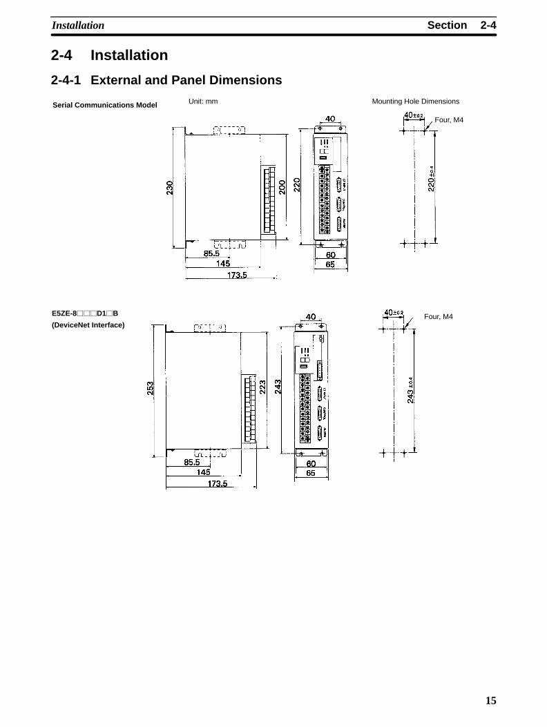
2-4-1 External and Panel Dimensions
Serial Communications Model
E5ZE-8D1B
(DeviceNet Interface)
Unit: mm Mounting Hole Dimensions
Four, M4
Four, M4

2-4SectionInstallation
16
2-4-2 MountingMount the Unit using the methods shown here. The Unit will not operate properlyif other methods are used to mount the Unit.
Precautions• Use the following mounting screws. Make sure the length of the screws is ap-
propriate for the mounting panel used.
E5ZE-8B: 4 x M4 screws
• Use spring and flat washers and tighten to a torque of 0.43 to 0.58 N m 4.4 to5.9 kgf cm.
• Do not mount the terminal block with the connectors facing upwards. Doing somay cause measurement errors.
Secure the mounting bracket using the screws provided according to the ap-propriate mounting method. Tighten to a torque of 0.43 to 0.58 N m 4.4 to5.9 kgf cm.
Mounting Models
Secure the mountingbracket Mounting screws
(4 x M4 + springand flat washers)
Secure the mountingbracket
Mounting screws(4 x M4 + springand flat washers)
Panel
Panel
Mounting Bracket
2-5SectionPower Supply and Input Wiring
17
2-5 Power Supply and Input Wiring
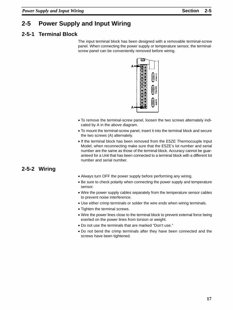
2-5-1 Terminal BlockThe input terminal block has been designed with a removable terminal-screwpanel. When connecting the power supply or temperature sensor, the terminal-screw panel can be conveniently removed before wiring.
• To remove the terminal-screw panel, loosen the two screws alternately indi-cated by A in the above diagram.
• To mount the terminal-screw panel, insert it into the terminal block and securethe two screws (A) alternately.
• If the terminal block has been removed from the E5ZE Thermocouple InputModel, when reconnecting make sure that the E5ZE’s lot number and serialnumber are the same as those of the terminal block. Accuracy cannot be guar-anteed for a Unit that has been connected to a terminal block with a different lotnumber and serial number.
2-5-2 Wiring• Always turn OFF the power supply before performing any wiring.
• Be sure to check polarity when connecting the power supply and temperaturesensor.
• Wire the power supply cables separately from the temperature sensor cablesto prevent noise interference.
• Use either crimp terminals or solder the wire ends when wiring terminals.
• Tighten the terminal screws.
• Wire the power lines close to the terminal block to prevent external force beingexerted on the power lines from torsion or weight.
• Do not use the terminals that are marked “Don’t use.”
• Do not bend the crimp terminals after they have been connected and thescrews have been tightened.

2-5SectionPower Supply and Input Wiring
18
• Use the crimp terminals shown in the following diagram.
Crimp Terminals
End Soldering
Terminal Block Screw Dimensions
9.5 mm
8.1 mm 8 x M3.5 self-rising screws
7.9 mm max.
7.9 mm max.
Length of exposed wire: 6 to 8 mm
Applicable wire size: AWG 22 to 16
2-5-3 Terminal ArrangementThe following diagram shows the arrangement of terminals on the terminalblock.
Thermocouple Platinum Resistance Thermometer
24 VDC 24 VDC
ch 0
ch 1
ch 2
ch 3
FG
Don’t use
Don’t use
Don’t use
ch 4
ch 5
ch 6
ch 7
Don’t use
Don’t use
Don’t use
ch 0
ch 1
ch 2
ch 3
FG
Don’t use
ch 4
ch 5
ch 6
ch 7
Don’t use
2-5-4 Power SupplyThe power supply specifications are as follows:24 VDC (20.4 to 26.4 VDC) 15 W + 20% max.
Use a power supply with a minimum capacity of 2 A. Be sure to consider the in-rush current.
2-5-5 GroundConnect the ground wire to terminal 26. Ground to 100 Ω max.

2-6SectionWiring CT Inputs and Control/Alarm Outputs
19
2-5-6 Thermocouple Input• The terminal polarity varies with the control point. Be sure to check polarity
when connecting thermocouples to the terminal block.
• When extending the input lead wires, connect compensating conductors thatmatch the thermocouple used. Do not solder the ends of the thermocouple orcompensating conductors.
• Never remove the cold junction compensator connected to terminals 13 and15.
• Do not touch the cold junction compensators.
• Short-circuit the positive and negative terminals of each control point that is notused. The process value for each control point that is not being used will be theambient temperature of the terminal block.
2-5-7 Platinum Resistance Thermometer Input• The terminal polarity varies with the control point. Be sure to check polarity
when connecting platinum resistance thermometers to the terminal block.
• When extending the input lead wires, make sure that the conductor resistanceis the same for the A terminal and two B terminals.
• Connect a 100- to 200-Ω resistor between the A and B terminals of any unusedcontrol point, and short-circuit the two B terminals of any unused control point.The process value for each control point that is not being used will correspondto the resistance of the resistor connected to the terminals.
2-6 Wiring CT Inputs and Control/Alarm OutputsCT inputs and control/alarm outputs are connected using wiring-reduction de-vices. Always use E5ZE-CBL Connecting Cables to connect the E5ZE tothe wiring-reduction devices. Refer to the wiring-reduction device datasheet fordetails, including wiring precautions.
Use the identification labels provided for each cable to prevent incorrect wiring ofthe CONTROL, ALARM, and CT INPUT connectors.
Cable identification label
Hood: Connect tothe FG terminal.
FG terminal: Connect toimprove noise resistance
E5ZE-CBL Connecting Cable

2-6SectionWiring CT Inputs and Control/Alarm Outputs
20
2-6-1 CT InputsThe CT INPUT connector can be connected to an XW2B-20G5 Connector Ter-minal Conversion Unit (20-terminal M3.5 terminal block) or an XW2B-20G4Connector Terminal Conversion Unit (20-terminal M2.4 terminal block).
Cable Connections
E5ZE-CBL Connecting Cable
XW2B-20G5/4 Connector TerminalConversion Unit
CT0 to CT7
WiringThe following diagram shows the terminal arrangement for CT inputs when aXW2B-20G5/4 Connector Terminal Conversion Unit is connected. Connect CT0to CT7 to the CT inputs for control points 0 to 7. For example, CT0 will detectheater burnout or SSR failure for the output of control point 0.
Use the E54-CT1 or E54-CT3 Current Transformer (CT). Refer to Appendix Bfor further details on the CT. Refer to 3-10 Heater Burnout Detection for detailson wiring the CT.

2-6SectionWiring CT Inputs and Control/Alarm Outputs
21
2-6-2 Outputs
Cable Connections
E5ZE-CBL
Connecting Cable
XW2B-20G5/4 Connector TerminalConversion Unit
Heating control output, memory bank designation input
G7TC-OC08/16, G7VC-O16I/O Blocks
Cooling control output, ALM1 and ALM2, HB alarm,HS alarm, temperature controller error
XW2B-20G5/4 Connector TerminalConversion Unit
The CONTROL connector can be connected to an XW2B-20G5 Connector Ter-minal Conversion Unit (20-terminal M3.5 terminal block) or an XW2B-20G4Connector Terminal Conversion Unit (20-terminal M2.4 terminal block).
• The terminal arrangement for outputs when an XW2B-20G5/4 Connector Ter-minal Conversion Unit is connected is shown in the following diagram.
CONTROL Connector Terminal Block
212220
• The output specifications are shown in the following table. Connect a load thatis compatible with the output type and output rating.
Output Specification
Voltage output Output voltage: 12 ± 1.2 VDC
Output current: 30 mA max.
Current output Output current: 4+0/–0.6 to 20+2/–0 mA DC
Load resistance: 600 Ω max.
CONTROL ConnectorWiring

2-6SectionWiring CT Inputs and Control/Alarm Outputs
22
• When connecting a relay load, insert a diode to prevent surge.
E5ZE
ch n: Control point 0 to 7
ch n +
ch n –
Relay
• The following diagram shows the wiring when designating the memory bankusing contact inputs.
No Contact InputContact Input
E5ZE
Terminalnumbers 2,3, and 4
Terminalnumber 1
E5ZE
Terminalnumbers 2,3, and 4
Terminalnumber 1
ON: Short-circuit resistance: 1 kΩ max.
Outflow current: 3 mA DC
OFF: Open resistance: 100 kΩ min.
ON: Residual voltage: 2 VDC max.
Outflow current: 3 mA DC
OFF: Leakage current: 1 mA max.
The ALARM connector can be used with the following devices.
• XW2B-20G5 or XW2B-20G4 Connector Terminal Conversion Unit
• G7TC-OC16, G7TC-OC08, or G7VC-O16 I/O Block
The following diagram shows the terminal arrangement when the ALARM con-nector is connected to an XW2B-20G5 or XW2B-20G4 Connector TerminalConversion Unit. In the diagram, RL indicates a relay load.
Cooling control output (Do not use these terminals with E5ZE-8A Standard Models.)
Don’t use
Don’t use Don’t use Don’t use Don’t use
Common
Common
Temperature controller error
HS alarm HB alarm Alarm 2 Alarm 1
ch 7 ch 6 ch 5 ch 4 ch 3 ch 2 ch 1 ch 0
• The following table shows the specifications for alarm output and cooling con-trol output. The E5ZE does not have an overcurrent protection function foralarm output and cooling control output. Connect a load to each alarm outputand cooling control output that corresponds to the output ratings.
Output Specifications
Open collector output NPN, 30 VDC, 50 mA max.
Residual voltage when ON: 2 VDC max.
Leakage current when OFF: 1 mA max.
• Do not use the terminals marked “Don’t use.”
ALARM Connector Wiring
2-6SectionWiring CT Inputs and Control/Alarm Outputs
23
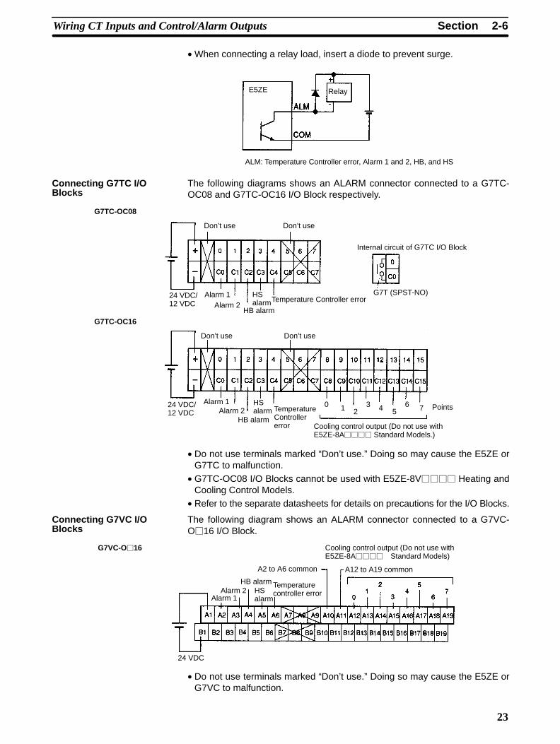
• When connecting a relay load, insert a diode to prevent surge.
E5ZE Relay
ALM: Temperature Controller error, Alarm 1 and 2, HB, and HS
The following diagrams shows an ALARM connector connected to a G7TC-OC08 and G7TC-OC16 I/O Block respectively.
G7TC-OC08
G7TC-OC16
Don’t use Don’t use
24 VDC/12 VDC
Alarm 1Alarm 2
HB alarm
HSalarmTemperature Controller error
Cooling control output (Do not use withE5ZE-8A Standard Models.)
Internal circuit of G7TC I/O Block
G7T (SPST-NO)
Don’t use Don’t use
24 VDC/12 VDC
Alarm 1Alarm 2
HB alarm
HSalarm Temperature
Controllererror
0 1 23 4 5
6 7 Points
• Do not use terminals marked “Don’t use.” Doing so may cause the E5ZE orG7TC to malfunction.
• G7TC-OC08 I/O Blocks cannot be used with E5ZE-8V Heating andCooling Control Models.
• Refer to the separate datasheets for details on precautions for the I/O Blocks.
The following diagram shows an ALARM connector connected to a G7VC-O16 I/O Block.
G7VC-O16
24 VDC
Alarm 1Alarm 2
HB alarmHSalarm
Temperaturecontroller error
Cooling control output (Do not use withE5ZE-8A Standard Models)
A2 to A6 common A12 to A19 common
• Do not use terminals marked “Don’t use.” Doing so may cause the E5ZE orG7VC to malfunction.
Connecting G7TC I/OBlocks
Connecting G7VC I/OBlocks

2-7SectionConnecting Communications
24
• The following G7VC-O16 I/O Blocks for output are available.
G7VC-OC16: Relay outputs
G7VC-OA16: SSR AC outputs
G7VC-OD16: SSR DC outputs
• Refer to the separate datasheets for details on precautions for the I/O Blocks.
2-7 Connecting CommunicationsThe wiring and connections of the communications interfaces are describedhere. For further details, refer to the following manuals.
Serial communications: E5ZE Multipoint Temperature Controller Communica-tions Manual (H77)
DeviceNet communications: E5ZE-8 Multipoint Temperature Controller Devi-ceNet Communications Manual (H104)
2-7-1 RS-232C• Mount the RS-232C Communications Unit on the E5ZE Serial Communica-
tions Model.
• The E5ZE is connected to the RS-232C interface in the ratio of 1:1.
• Refer to the E5ZE Multipoint Temperature Controller Communications Manual(H77) for details on communications.
Cable Connections• The maximum cable length is15 m. To extend the transmission path, use the
OMRON Z3RN RS-232C Optical Interface.
• Use shielded twisted-pair cable with a wire thickness of AWG28 minimum.
• Use the following OMRON 25-pin D-sub Connectors or equivalent.
Plug: XM2A-2501 Connector
Hood: XM2S-2511 Hood
Host deviceRS-232C
Sym-bol
Pin
Shield Pin Sym-bol
E5ZE
LT1181CS orequivalent
Line driver/receiver
• The E5ZE’s RS-232C communications do not support a CD (carrier detect)signal from the host device. If the CD signal is required, provide support at thehost device.
When using the RS-232C auxiliary setting jack on the E5ZE-8D1B(DeviceNet Model with casing), use the following Connecting Cables.
• ES100-CT021-202 (25-pin)
This Cable is used to connect the E5ZD-SDL1 Setting Display Unit.
• ES100-CT023-202 (9-pin)
The RS-232C auxiliary setting jack is designed to be used only temporarily forinitial settings and performing maintenance. Do not use the RS-232C auxiliarysetting jack to mount the E5ZE to a device. If the RS-232C auxiliary setting jackis left connected for a long time, the reliability of the connection will deteriorate.

2-7SectionConnecting Communications
25
2-7-2 RS-422 and RS-485
• Mount the RS-422/485 Communications Unit on the E5ZE Serial Communica-tions Model.
• The E5ZE can be connected to the communications interface in the ratio of 1:Nwith a maximum of 16 Units connected.
• The maximum cable length is 500 m.
• Refer to the E5ZE Multipoint Temperature Controller Communications Manual(H77) for further details on communications.
Parameter Settings• Specify the following parameters using the communications DIP switch. Al-
ways turn OFF the power before changing the switch.
• Communications interface
• Terminating resistance
E5ZE-804
Setting Pin RS-422 RS-485
Terminatingresistance
Yes Pin 4Pin 3
(pins 3 and 4)No Pin 4
Pin 3
Interface (pins 1 and 2) Pin 2Pin 1
• Set the terminating resistance at both ends of the transmission path includingthe host device. If terminating resistance is to be set at devices other than theE5ZE, make sure that the total terminating resistance value of the transmis-sion paths is at least 100 Ω.
Wiring the Communications Terminal Block• Always turn OFF the power supply before wiring.
• Wire the power lines and communications cables separately to prevent noiseinterference.
• Use crimp terminals or solder the wire ends when wiring the terminals.
• Tighten the terminal screws to a torque of 0.59 N m, or 6 kgf cm.
• Do not apply a force of more than 100 N or 10.2 kgf to the terminal screws.
• Do not bend any crimp terminals after connecting them to the terminal screwsand tightening.
2-7SectionConnecting Communications
26
• The following crimp terminals can be used.
Crimp Terminal Terminal Block Screw Dimensions
End Soldering
6 mm max.
6 mm max.
10.4 mm
6.25 mm M3 x 7.2 screws withsquare washers
Applicable wire size: AWG14 to 20
Shielded twisted-pair cable
Length of exposed wire: 6 to 7 mm
RS-422 Wiring
Host device
Signal
E5ZE
Termi-
nalSignal
Shield
SN751177N orequivalent
Communications DIP switch
Terminating resistance
E5ZE
Termi-
nalSignal
6.8 V
51 k
51 k
4.7 k
4.7 k
+5 V

2-7SectionConnecting Communications
27
RS-485 Wiring• Do not use terminals 1 and 2.
Host device
SignalE5ZE
Termi-
nalSignal
Shield
SN751177N orequivalent
Communications DIP switch
Terminating resistance
E5ZE
Termi-
nal Signal
6.8 V
4.7 k51 k
4.7 k
51 k
+5 V
2-7-3 DeviceNet Interface• Use the E5ZE-8D1B for DeviceNet communications.
• Refer to the DeviceNet Operation Manual (W267) for details on DeviceNetNetwork configurations and connection methods.
• Refer to the E5ZE-8 DeviceNet Communications Manual (H104) for details onDeviceNet communications applications.
Set the following parameters using the DeviceNet DIP switch.
• Node addresses
• Baud rate
• E5ZE operation for DeviceNet communications errors.
DeviceNet DIP
switch
DeviceNet
connector
RS-232C auxiliary
setting jack
Node addressCommunications error operations
Always set to OFF
Baud rate
• Pins 1 to 6 are used to set the node address. The factory setting is 00 (pins 1 to6 all OFF).
Pin 1 Pin 2 Pin 3 Pin 4 Pin 5 Pin 6
20 21 22 23 24 25
Communications Settings

2-7SectionConnecting Communications
28
• Pins 7 and 8 are used to set the baud rate. Be sure to set the baud rate to matchthat of the DeviceNet Master Unit. The factory setting is 125 kbps (pins 7 and 8OFF).
Baud rate Pin 7 Pin 8
125 kbps OFF OFF
250 kbps ON OFF
500 kbps OFF ON
Not used ON ON
• Pin 10 is used to set the E5ZE operation when a DeviceNet communicationserror occurs.
ON: The E5ZE continues to operate according to the data that wastransmitted immediately before the error occurred.
OFF: The E5ZE stops operating.
The factory setting is ON.
• A DeviceNet transmission error is a connection time-out error or a transmis-sion data error that has occurred during communications between the Devi-ceNet Master and the E5ZE.
Cable Connections• The following diagram shows how the DeviceNet connector is wired.
• Multi-drop connections cannot be used.
Black (V–)
Blue (CAN L)
Shield
White (CAN H)
Red (V+)
The number of E5ZE-8D1B DeviceNet Models with casing that can beconnected to one DeviceNet Master Unit depends on the capability of the Masterbeing used. The maximum number of Units that can be connected to one Masteris calculated according to the number of words allocated to theE5ZE-8D1B and the number of words that can be used by the Master.
• The number of words allocated to the E5ZE-8D1B is as follows:
Inputs: 14 words
Outputs: 9 words
Message communications (FINS messages) are used.
Example: C200HW-DRM21-V1 DeviceNet Master Unit without Configurator
• The number of words used by the Master is 50 input words and 50 outputwords (current as of July 31, 1998). The E5ZE-8D1B is allocated14 words, so the maximum number of Units that can be connected is as fol-lows:
50 14 = 3 Units.
Number of ConnectableUnits

29
SECTION 3Functions
This section provides details on the functions of the E5ZE and their applications. For details on the settings and measurementvalues for the functions, refer to the E5ZE Multipoint Temperature Controller Communications Manual (H77) and theE5ZE-8 Multipoint Temperature Controller DeviceNet Communications Manual (H104).
3-1 Data Configuration 30. . . . . . . . . . . . . . . . . . . . . . . . . . . . . . . . . . . . . . . . . . . . . . . . . . . . . . . . 3-2 I/O Settings 31. . . . . . . . . . . . . . . . . . . . . . . . . . . . . . . . . . . . . . . . . . . . . . . . . . . . . . . . . . . . . .
3-2-1 Input Type 31. . . . . . . . . . . . . . . . . . . . . . . . . . . . . . . . . . . . . . . . . . . . . . . . . . . . . . . 3-2-2 Input Shift 31. . . . . . . . . . . . . . . . . . . . . . . . . . . . . . . . . . . . . . . . . . . . . . . . . . . . . . . 3-2-3 Control Period 31. . . . . . . . . . . . . . . . . . . . . . . . . . . . . . . . . . . . . . . . . . . . . . . . . . . . 3-2-4 Direct/Reverse Operation 32. . . . . . . . . . . . . . . . . . . . . . . . . . . . . . . . . . . . . . . . . . .
3-3 Set Point and Process Value 32. . . . . . . . . . . . . . . . . . . . . . . . . . . . . . . . . . . . . . . . . . . . . . . . . 3-3-1 Setting Set Point 32. . . . . . . . . . . . . . . . . . . . . . . . . . . . . . . . . . . . . . . . . . . . . . . . . . 3-3-2 Reading Process Value 32. . . . . . . . . . . . . . . . . . . . . . . . . . . . . . . . . . . . . . . . . . . . . .
3-4 Alarm Output Settings 33. . . . . . . . . . . . . . . . . . . . . . . . . . . . . . . . . . . . . . . . . . . . . . . . . . . . . 3-4-1 Alarm Modes 33. . . . . . . . . . . . . . . . . . . . . . . . . . . . . . . . . . . . . . . . . . . . . . . . . . . . . 3-4-2 Alarm Temperatures 34. . . . . . . . . . . . . . . . . . . . . . . . . . . . . . . . . . . . . . . . . . . . . . .
3-5 Output Limitations 35. . . . . . . . . . . . . . . . . . . . . . . . . . . . . . . . . . . . . . . . . . . . . . . . . . . . . . . . 3-5-1 Output Limiter 35. . . . . . . . . . . . . . . . . . . . . . . . . . . . . . . . . . . . . . . . . . . . . . . . . . . . 3-5-2 Output Change Rate Limiter 35. . . . . . . . . . . . . . . . . . . . . . . . . . . . . . . . . . . . . . . . .
3-6 Ramp 36. . . . . . . . . . . . . . . . . . . . . . . . . . . . . . . . . . . . . . . . . . . . . . . . . . . . . . . . . . . . . . . . . . 3-7 Control Adjustments 37. . . . . . . . . . . . . . . . . . . . . . . . . . . . . . . . . . . . . . . . . . . . . . . . . . . . . .
3-7-1 Auto-tuning 37. . . . . . . . . . . . . . . . . . . . . . . . . . . . . . . . . . . . . . . . . . . . . . . . . . . . . . 3-7-2 Manual Reset 39. . . . . . . . . . . . . . . . . . . . . . . . . . . . . . . . . . . . . . . . . . . . . . . . . . . . .
3-8 Control Method Selection 39. . . . . . . . . . . . . . . . . . . . . . . . . . . . . . . . . . . . . . . . . . . . . . . . . . 3-8-1 Manual Operation 39. . . . . . . . . . . . . . . . . . . . . . . . . . . . . . . . . . . . . . . . . . . . . . . . . 3-8-2 ON/OFF Control 40. . . . . . . . . . . . . . . . . . . . . . . . . . . . . . . . . . . . . . . . . . . . . . . . . .
3-9 Heating and Cooling Control 41. . . . . . . . . . . . . . . . . . . . . . . . . . . . . . . . . . . . . . . . . . . . . . . . 3-9-1 Dead Band/Overlap Band 41. . . . . . . . . . . . . . . . . . . . . . . . . . . . . . . . . . . . . . . . . . . 3-9-2 Cooling Coefficient 42. . . . . . . . . . . . . . . . . . . . . . . . . . . . . . . . . . . . . . . . . . . . . . . .
3-10 Heater Burnout Detection 42. . . . . . . . . . . . . . . . . . . . . . . . . . . . . . . . . . . . . . . . . . . . . . . . . . . 3-11 SSR Failure Detection 44. . . . . . . . . . . . . . . . . . . . . . . . . . . . . . . . . . . . . . . . . . . . . . . . . . . . .

30
3-1 Data ConfigurationThe following diagram shows how data is structured in the E5ZE.
Set point
Proportional band (P constant)
Integral time (I constant)
Derivative time (D constant)
Control period
Alarm temperature
Input shift value
Manual reset value
Output limit
Ramp value
Output change rate limit
Dead band/overlap band (Seenote.)
Cooling coefficient (See note.)
Fuzzy strength
Fuzzy scale 1
Fuzzy scale 2
Memory Bank 7 Set Values
Memory Bank 1 Set Values
Common set values: Output operation (direct/reverse operation)
Setting unit
HB alarm, HS alarm valid control points
CH0 (Control Point 0) Set Values
Memory bank number
Alarm mode
Manual output value
HB alarm, HS alarm detectioncurrent value
Memory Bank 0 Set Values
Set point
Proportional band (P constant)
Integral time (I constant)
Derivative time (D constant)
Control period
Alarm temperature
Input shift value
Manual reset value
Output limit
Ramp value
Output change rate limit
Dead band/overlap band (Seenote.)
Cooling coefficient (See note.)
Fuzzy strength
Fuzzy scale 1
Fuzzy scale 2
Memory Bank 7 Set Values
Memory Bank 1 Set Values
CH1 (Control Point 1) Set Values
Memory bank number
Alarm mode
Manual output value
HB alarm, HS alarm detectioncurrent value
Memory Bank 0 Set Values
Set point
Proportional band (P constant)
Integral time (I constant)
Derivative time (D constant)
Control period
Alarm temperature
Input shift value
Manual reset value
Output limit
Ramp value
Output change rate limit
Dead band/overlap band (Seenote.)
Cooling coefficient (See note.)
Fuzzy strength
Fuzzy scale 1
Fuzzy scale 2
Memory Bank 7 Set Values
Memory Bank 1 Set Values
CH7 (Control Point 7) Set Values
Memory bank number
Alarm mode
Manual output value
HB alarm, HS alarm detectioncurrent value
Memory Bank 0 Set Values
Note The cooling coefficient and dead band/overlap band are applicable only toE5ZE-8V Heating and Cooling Control Models.
The E5ZE has 8 memory banks, 0 to 7, for each control point. The memorybanks store specific groups of setting data. The E5ZE controls each control pointaccording to the contents of the current memory bank.• All set values are written (set) or read using communications. The control point
number and memory bank number must be specified for each command. ForDeviceNet, however, the control point and memory bank numbers do not al-ways need to be specified.
• When DeviceNet (remote I/O) is used, set values will be read and written ac-cording to the current memory bank.
Memory banks are designated using contact inputs or through communications.The method of memory bank designation is set using pin 3 of the FUNCTIONswitch. Refer to 2-3 Setting Selectors and Switch for details on setting methods.• When the E5ZE is turned ON, the memory banks previously selected through
communications will be in effect.
Set Values
Memory Banks
Memory Bank Designation
Data Configuration Section 3-1

31
• The memory bank numbers for control points that are being auto-tuned cannotbe changed.
• The following table shows the designation methods and functions of thememory banks.
Item Operation Function
Setting thememory banknumber
Throughcommunications
A memory banknumber isdesignated foreach control pointthroughcommunications.
The differentmemory banknumbers can bedesignated foreach control point.
Using contactinputs
A memory banknumber isdesignated bysetting contactsMB0 to MB2 onthe terminal blockconnected to theCONTROLconnector.
All control pointswill switch to thedesignatedmemory banknumber.
Confirming the selected memory banknumber
A control point canbe designated andread throughcommunications tocheck the memorybank.
---
The following table shows the status of MB0 to MB2 and their relation to the des-ignated memory bank.
MemoryBank
0 1 2 3 4 5 6 7
MB0 --- ON --- ON --- ON --- ON
MB1 --- --- ON ON --- --- ON ON
MB2 --- --- --- --- ON ON ON ON
The dashed line “---” indicates that the input is OFF.
3-2 I/O Settings3-2-1 Input Type
The E5ZE is available in models that can be used for thermocouple inputs orplatinum resistance thermometer inputs.The input type is set using the INPUT selector on the front panel of the Unit. Re-fer to 2-3 Setting Selectors and Switch for details on settings.
3-2-2 Input ShiftSet the input shift parameter in each memory bank.The input shift function adds the value set for the input shift to the process valueand the E5ZE then controls using this temperature as the process value. For ex-ample, if the process value is 100°C and the input shift is –12°C, the E5ZE willuse 100°C – 12°C = 88°C as the process value for control.The input shift setting range is –99.9 to 99.9°C or –99.9 to 99.9°F (default: 0.0°Cor 0.0°F.)
3-2-3 Control PeriodIf the Voltage Output Model is being used, set the control period in each memorybank.Set the length of the control output period. The setting range is between 1 and99 s (default: 2 s). For direct operation, the default can be used.
I/O Settings Section 3-2

32
3-2-4 Direct/Reverse OperationThe direct/reverse operation parameter is the same for all control points.
Reverse operation is used for heating control and direct operation is used forcooling control.
The default is 0000, i.e., all control points will operate in reverse (heating con-trol).
3-3 Set Point and Process ValueThe setting for the set point used to control the temperature and the process val-ue includes a temperature unit and a setting unit.
The temperature unit (°C or °F) is specified using pin 6 of the FUNCTION switchon the front panel of the Unit. Refer to 2-3 Setting Selectors and Switch for de-tails on settings.
The setting unit is set using the setting unit parameter as either 0 or 0.1 (default).If serial communications are used to read the set point and process value data, 4digits will be indicated if the setting unit is “0” and 5 digits will be indicated if thesetting unit is “0.1.”
The same setting unit is used for all control points.
3-3-1 Setting Set PointSet the set point using the Set Point Write (WS) command in each memory bankof each control point.
If DeviceNet communications are being used, the values in the memory of thehost devices will be automatically reflected in the settings.
The default is 0.0°C or 0.0°F.
3-3-2 Reading Process ValueRead the process value using the Process Value Read (RX) command. The pro-cess value will be read for each control point.
If DeviceNet is used, the values in the memory of the host device will be automat-ically read.
The setting unit is used as the unit for the alarm temperature and current controltemperature during ramp control, as well as for the set point and process value.
The settings will not be affected if the setting unit is changed. If the settings areread, however, they will be indicated as follows:
• If the setting unit is set to 0.1, and data is read after changing the setting unit to0, any value after the decimal point will be rounded off to a whole integer. Forexample, 1234.5 will be read as 1235.
• If the setting unit is set to 0, and data is read after changing the setting unit to0.1, a zero will be added after the decimal point. For example, 1234 will be readas 1234.0.
Operation Start and Stop• Execute the Operation Start (OS) command for each control point to start tem-
perature control.
• Execute the Operation Stop (OP) command to stop temperature control ormanual operation.
• When DeviceNet communications are used, specific bits are allocated in thememory of the host device for starting and stopping temperature control. Tem-perature control is started and stopped by turning the corresponding bit ON orOFF.
Setting Unit
Set Point and Process Value Section 3-3
33
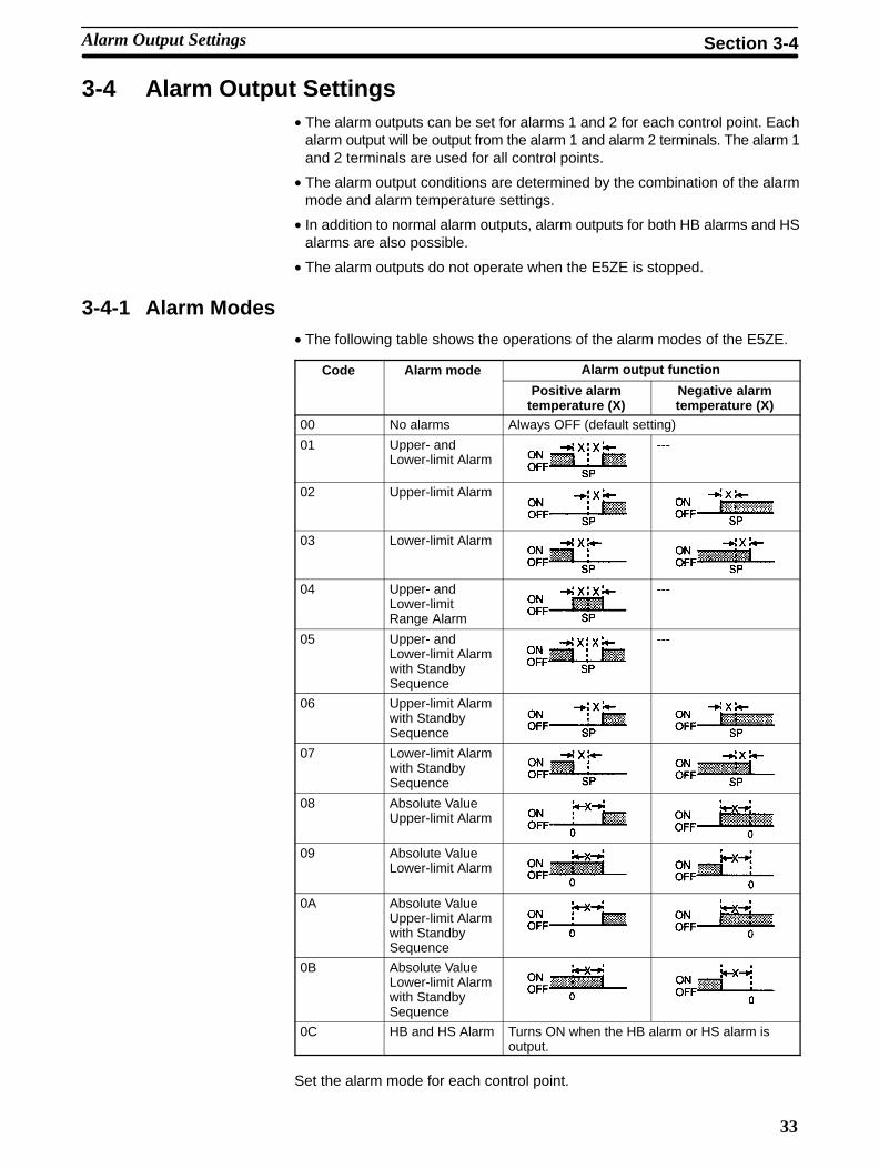
3-4 Alarm Output Settings• The alarm outputs can be set for alarms 1 and 2 for each control point. Each
alarm output will be output from the alarm 1 and alarm 2 terminals. The alarm 1and 2 terminals are used for all control points.
• The alarm output conditions are determined by the combination of the alarmmode and alarm temperature settings.
• In addition to normal alarm outputs, alarm outputs for both HB alarms and HSalarms are also possible.
• The alarm outputs do not operate when the E5ZE is stopped.
3-4-1 Alarm Modes• The following table shows the operations of the alarm modes of the E5ZE.
Code Alarm mode Alarm output function
Positive alarmtemperature (X)
Negative alarmtemperature (X)
00 No alarms Always OFF (default setting)
01 Upper- andLower-limit Alarm
---
02 Upper-limit Alarm
03 Lower-limit Alarm
04 Upper- andLower-limitRange Alarm
---
05 Upper- andLower-limit Alarmwith StandbySequence
---
06 Upper-limit Alarmwith StandbySequence
07 Lower-limit Alarmwith StandbySequence
08 Absolute ValueUpper-limit Alarm
09 Absolute ValueLower-limit Alarm
0A Absolute ValueUpper-limit Alarmwith StandbySequence
0B Absolute ValueLower-limit Alarmwith StandbySequence
0C HB and HS Alarm Turns ON when the HB alarm or HS alarm isoutput.
Set the alarm mode for each control point.
Alarm Output Settings Section 3-4

34
3-4-2 Alarm Temperatures• The alarm temperatures are indicated by X in the above alarm mode table. The
operation differs depending on whether the value is positive or negative.
• Set the alarm temperature in each memory bank. The alarm temperature set-ting is not required, however, if the alarm mode is set to 00 (no alarm function)or 0C (HB and HS alarm).
The Standby Sequence enables delaying output of an alarm until the processvalue enters the alarm range from outside the alarm range.
For example, if the alarm mode is set to Lower-limit Alarm without Standby Se-quence, and the ambient temperature is lower than the alarm set value (i.e.,within the alarm range), the alarm output will turn ON at startup. If, under thesame conditions, the alarm mode is set to Lower-limit Alarm with Standby Se-quence, the alarm output will only turn ON when the process value rises onceabove the alarm set value (i.e., outside the alarm range) and then drops backbelow it (i.e., within the alarm range).
• When the alarm output turns ON, the standby sequence operation will be en-ded. The standby sequence will restart again, however, under the followingconditions.
• If temperature control or manual operation is started.
• If the power is turned ON.
• If the set point is changed.
• If the alarm temperature is changed during operation.
The following time-chart shows an example of the Lower-limit Alarm with Stand-by Sequence Mode.
Alarm mode: Lower-limit with Standby Sequence
Process value
Standby sequenceended
Alarm
Time
Alarm temperature
Alarm hysteresis
The alarm hysteresis is a fixed value: 1.0°C, 1.0°F
Standby Sequence
Alarm Operation Summary
Alarm Output Settings Section 3-4

35
3-5 Output LimitationsThe upper and lower limits for the output value are limited by an output limiterand the output change rate is limited by an output change rate limiter.
3-5-1 Output LimiterIf the output value calculated by the E5ZE is outside the range of the output limit-er, the actual output will be restricted to the specified upper or lower limit.
Output value (%)
Output limiter
Upper limit
Output limiter
Lower limit
• Set the upper limit and the lower limit within the range of 0.0% to 100.0%.
• The lower limit cannot be set to a value greater than the upper limit.
• If the lower limit is 100.0, the output value will be 100.0%.
• If the upper limit is 0.0, the output value will be 0.0%.
• If the upper limit is equal to the lower limit, the output value will be equal to theoutput limits.
3-5-2 Output Change Rate LimiterThe change in output value during one sampling period (approx. 200 ms) is lim-ited by the output change rate limiter. If the output value calculated by the E5ZEchanges too quickly, the actual output will be that allowed by the setting of theoutput change rate limiter and will gradually change until it reaches the calcu-lated output value.
Output value (%)
Time
Point of change
Calculated output value
Change ratelimit value
200 ms
• The change rate limit setting range is between 0.0% and 100.0% per 200 ms.The change rate limiter is disabled if the value is set to 0.0 (default).
• Use the following formula to calculate and set the change rate limit when thechange rate is A% for 1 s of output.
Standard Control Models: A x 0.2
Heating and Cooling Control Models: A x 0.2 x 0.5
• The output change rate limiter will operate for both heating control and coolingcontrol.
Output Limitations Section 3-5

36
The limiter will be disabled and settings will not be required under the followingconditions.
• During manual operation.
• When a temperature sensor input error or temperature controller error occurs.
• When operation is stopped.
• During ON/OFF control.
• During auto-tuning (applies to the output change rate limiter only).
3-6 RampIf the ramp function is enabled and the change in the set point exceeds the speci-fied rate of change, the set point will change over an interval, as shown in thefollowing diagram. Temperature will be controlled during the ramp interval ac-cording to the value limited by this rate of change (i.e., the current set point), andnot by the new set point.
Set point
Set point afterchanging
Set point beforechanging
Point of change
Ramp interval
Ramp value
Ramp time unit
Time
• Set the change rate of the ramp interval in each memory bank. The ramp valueand the ramp time unit (hour, minute, or second) must also be set.
• The setting range is 0.1 to 99.9 (°C or °F divided by the ramp time unit).Thedefault is 0.0, i.e., the ramp function is disabled.
The ramp function will be used at the following times.
• When temperature control is started.
• When a memory bank number is changed.
• When the set point is changed.
The ramp function will be ended at the following times.
• When manual operation is started.
• When auto-tuning is executed.
If set points and ramp values are reset in memory banks in advance and thememory bank is switched from the host device over time, the following type oftrapezoidal control will be achieved.
Set point (°C)
Memorybank 0
Memorybank 1
Memorybank 2
Time
Limiter OperationConditions
Enable Conditions
Disable Conditions
Application Example
Ramp Section 3-6

37
3-7 Control Adjustments
3-7-1 Auto-tuningAuto-tuning (AT) can be executed independently for any control point, or can beexecuted for all control points simultaneously or in sequence. (If the DeviceNetis being used, auto-tuning cannot be executed in sequence.)
• If auto-tuning is cancelled, the auto-tuning will stop for all control points at thesame time. (If the DeviceNet is being used, auto-tuning can be stopped foreach control point separately.)
• When auto-tuning is executed, the optimum PID constants and fuzzy scale forthe set point will be automatically set in the current memory bank. The follow-ing set values will be changed.
Proportional band (P constant), integral time (I constant), derivative time (Dconstant), fuzzy scale 1, fuzzy scale 2
• The AT indicator will be lit while auto-tuning is being executed.
• A method of obtaining the characteristics of the controlled object (the limitcycle method), by causing the output value to fluctuate is used. The applicationof the method, however, will vary depending on whether the deviation (the dif-ference between the set point value and the process value) is greater or lessthan 100°C or 180°F when auto-tuning is started.
Deviation 100°C or 180°FDeviation 100°C or 180°F
Deviation:100°C or 180°F
Deviation:100°C or 180°F
Auto-tuning starts Auto-tuning startsAuto-tuning stops Auto-tuning stops
TimeTime
Set pointSet point
Limit cycle: Small fluctuations inoutput value (40%)
Limit cycle: Small fluctuations inoutput value (40%)
• If auto-tuning is executed for ON/OFF control, auto-tuning will be executedwith large fluctuations in the output value. After auto-tuning is completed,2-PID control will be executed.
Auto-tuning starts Auto-tuning stops
Time
Set point
Limit cycle: Large fluctuations in output value (100%)
Control Adjustments Section 3-7

38
Operation during Auto-tuning• Auto-tuning cannot be executed when the E5ZE operation is stopped or it is
being operated manually.
• The auto-tuning execution time may be extended depending on the controlledobject. In such a case, the time required for auto-tuning to be completed maybe reduced if the proportional band (P constant) is set to 0.0. The E5ZE goesinto ON/OFF operation with oscillations increasing.
• If the optimum PID constants have not been obtained for the controlled object,set them manually.
• Hunting will occur during auto-tuning. If hunting is undesirable, set the PIDconstants manually.
• The HB and HS alarms will not operate for the control point during auto-tuning.
• If the power is turned OFF during auto-tuning, the E5ZE will stop auto-tuning.
• The auto-tuning function will not operate properly if the controlled object (load)is not connected to the E5ZE.
PID Constants• The following table shows the relationship between the PID constants and the
set point responses for the temperature being controlled. Refer to this tablewhen setting PID constants manually.
PID constant Set point response
Excessivevalue
Oscillation Time
Proportional Larger Decreases Decreases Longband Smaller Increases Increases Short
Integral time Larger Decreases Decreases Long
Smaller Increases Increases Short
Derivative time Larger Decreases Increases Long
Smaller Increases Decreases Short
Excessive value: Overshooting or undershooting
Oscillation: Hunting
The fuzzy control function is used when there is external disturbance, to sup-press overshooting or undershooting the temperature being controlled by theE5ZE and stabilize the set point within a short period.
• The fuzzy constants are automatically adjusted when the PID constants arechanged.
• If automatic adjustment of fuzzy constants is unsatisfactory, adjust themmanually referring to the following table.
Fuzzy constant External disturbance response
Excessivevalue
Oscillation Time
Fuzzy strength Large Decreases Increases ---
Small Increases Decreases
Fuzzy scale 1 Large Increases Decreases Longand fuzzyscale 2 Small Decreases Increases Short
Fuzzy Constants
Control Adjustments Section 3-7

39
3-7-2 Manual ResetThe manual reset function is used to correct a constant offset from the set pointafter a stable condition is obtained when using P or PD control.
• When an offset occurs, change the manual reset value as shown in the follow-ing graph.
• The setting range is between 0.0% and 100.0%. The default is 50%.
• The manual reset value can be set separately in each memory bank.
Temperature
Set point
Proportional band
Offset
Time
Time
Manual reset value changed
Output value (%)
Manual reset valueafter change
3-8 Control Method Selection
3-8-1 Manual OperationIn manual operation, the control output is operated with manually set output val-ues.
• Each control point can be switched to manual operation independently.
• In manual operation, set the output value through communications.
• If manual operation is continued after the power has been turned OFF or ifmanual operation is started when the E5ZE has stopped operation, the outputvalue will be 0.0%. In this case, reset the output value.
Control Method Selection Section 3-8

40
• When switching between manual operation and 2-PID control, the output val-ue will enter balanceless, bumpless operation.
Output value (%)Balanceless, bumplessoperation
Time
0
Output reset valueOutput switchManual operation
2-PID control
Power OFF or operationstopped
Operating Conditions• The manual output value can be set only during manual operation. The manual
output value cannot be set if there is a temperature sensor input error or a Tem-perature Controller error.
• Manual operation cannot be started if auto-tuning is being executed or there isa Temperature Controller error.
• The E5ZE-8D1B (DeviceNet Model) cannot be operated manually ifoperation has been stopped. Temperature control must be started with remoteI/O before manual operation can be started. For further details, refer to theE5ZE-8 Multipoint Temperature Controller DeviceNet Communications Manu-al (H104).
3-8-2 ON/OFF Control2-PID control can be switched to ON/OFF control by setting the proportionalband (P constant) to 0.0.
In ON/OFF control, hysteresis is used to stabilize operation when a change ismade to ON/OFF control. The following diagrams show the operation of controloutput during ON/OFF control.
Reverse operation Direct operation
Hysteresis Hysteresis
Set pointSet point
• Set the hysteresis in each memory bank. The settings are only valid when ON/OFF control is being used.
• The setting range is between 0.0 to 99.9 (°C or °F).
• The default value is 0.8°C or 1.5°F.
Hysteresis
Control Method Selection Section 3-8

41
3-9 Heating and Cooling Control• The E5ZE-8V Models are used for heating and cooling control.
• The heating and cooling control function is used for controlling temperatures ofobjects radiating heat, such as extruding molding machines. The temperatureof these objects is controlled using heating control and cooling control outputs.
3-9-1 Dead Band/Overlap BandThe dead band/overlap band function adjusts the output method for the propor-tional output value close to the set point. The following graphs show the heatingand cooling output when using proportional control.
Proportional output value (%)
Proportional output value (%)
Low temperatureSet point
High temperature
Low temperatureSet point
High temperature
Cooling control output
Heatingcontroloutput
Dead band
Cooling control output
Heatingcontroloutput
Overlap band
Process value
Process value
Dead Band Set Value 0
Dead Band Set Value 0
• If the dead band is too wide, hunting may result.
• Control output may occur within the dead band for other types of control apartfrom proportional control and ON/OFF control.
• Set the dead band in each memory bank.
• The setting range of the dead band is –999 to +999°C (or °F). The default is 0.
Heating and Cooling Control Section 3-9

42
• The following graph shows the output when the E5ZE is operating using ON/OFF control.
Output value (%) Dead band
Low temperatureSet point
High temperature
Cooling control output
Heatingcontroloutput
Process value
Heating hysteresisCooling hysteresis
Dead Band Set Value in ON/OFF Control 0
3-9-2 Cooling CoefficientThe difference between the heating characteristics and cooling characteristicsof the object being controlled may cause control by PID constants to be unsatis-factory. By changing the cooling coefficient, however, the balance betweenheating and cooling can be readjusted.
• The cooling coefficient operates according to the following formula.
Cooling P constant = P constant cooling coefficient
• Set cooling coefficients in each memory bank.
• The cooling coefficient setting range is 0.0 to 10.0. The default is 1.0.
• If the cooling coefficient is set to 0.0, the cooling control output value will be 0%.
3-10 Heater Burnout Detection
Leads connected to CT terminal
Heater power line
Heater burnout is detected using the following method.
1, 2, 3... 1. Connect the Current Transformer (CT) for the control point to the corre-sponding terminal on the CT input terminal block, and pass the power cablethrough the hole in the CT.
2. When current flows through the heater power lines, an AC current corre-sponding to the amount of current flow is generated in the CT. The heaterburnout detection function measures the generated AC current and obtainsthe amount of current flowing to the heater.
3. When the heater burns out, the current decreases, and after comparing thecurrent with the specified heater burnout detection current value, the HBalarm output will turn ON and the HB indicator will light.
Heater Burnout Detection Section 3-10

43
• Set the control points for which HB alarms will be enabled. The factory settingis for the HB alarm to be disabled for all control points. The HB alarm is set byexecuting the HB Alarm/HS Alarm Effective Control Point Setting (WU) com-mand. If DeviceNet communications are being used, set the HB alarm withFINS messages.
• Set the heater burnout detection current value. The setting range is between0.0 and 50.0 A.
• If the HB alarm is set to 0.0, it will always be OFF, and if it is set to 50.0, it willalways be ON. The default is 0.0 (always OFF).
• To check the CT current, read the values for the heater current and SSR leak-age current.
• If the HB alarm is output, it will turn OFF again once the heater current in-creases to a value greater than or equal to the heater burnout detection cur-rent.
• For direct operation, set the heater current to 50 A max. for each control point.If the heater current exceeds 50 A, heater burnout cannot be detected.
• Turn ON the heater power either at the same time as or before turning ON thepower to the E5ZE. The HB alarm output will turn ON if the power to the E5ZE isturned ON before turning ON the heater power.
• Temperature control will continue even when the HB alarm turns ON. (TheE5ZE will attempt to control the temperature for the heater that has burnt out.)
• The heater burnout detection function operates when the control output is con-tinuously ON for more than 100 ms.
• If the heater’s rated current does not match the actual current flowing throughthe heater, check the actual current being applied by reading the values for theheater current and the SSR leakage current.
• If the difference between normal heater current and heater burnout current issmall, the detection function will not operate properly. For reliable detection,use a heater that will give a current difference of at least 1.0 A for heaters thatare less than 10.0 A, and at least 2.5 A for heaters that are 10.0 A or more.
• The heater burnout detection function cannot be used when the heater is beingcontrolled by phase control or cycle control, or if a 3-phase heater is beingused.
• The heater burnout detection delay is 10 control periods max.
• The HB alarm will not operate for a control point during auto-tuning.
Use the K2CU-FA-GS Heater Burnout Alarm Unit, which has gate inputterminals, to detect heater burnout when using 3-phase heaters. (Refer to therelevant datasheets for further details.)
Calculate the set value for the heater burnout detection current using the follow-ing formula.
Normal heater current + Heater burnout current
2Heater burnout detection current set value =
• If more than two heaters are passed through the CT, set the heater burnoutdetection current to that for the heater with the smaller heater burnout detec-tion current value. (If the heater burnout detection current is the same for allheaters, set the value to the heater burnout detection current for one heater.)
• Heater burnout will be detected under the following conditions.
If heater current consumption is less than 10.0 A:
Normal heater current – Heater burnout current 1 A
Heater burnout may not be detected if the difference is less than 1 A.
Heater Burnout DetectionCurrent Value Calculation
Heater Burnout Detection Section 3-10

44
If heater current consumption is 10.0 A or more:
Normal heater current – Heater burnout current 2.5 A
Heater burnout may not be detected if the difference is less than 2.5 A.
Example 1: Using One 200-VAC, 1-kW Heater
Heater
1 kW
Control output
200 VAC
E5ZE-12
Normal heater current =
Heater burnout current = 0 A
Set value =
Normal current – burnout current = 5 – 0 = 5 A ( 1 A)
= 2.5 A
= 5 A ( 10 A)1000200
5 + 0
2
Example 2: Using Three 200-VAC, 1-kW Heaters
Heater
1 kW x 3
Control output
200 VAC
E5ZE-12
Normal heater current =
Heater burnout current for 1 heater =
Set value =
Normal current – Burnout current = 15 – 10 = 5 A ( 2.5 A)
= 12.5 A
3 = 15 A ( 10 A)1000200
15 +10
2
1000200
2 = 10 A
3-11 SSR Failure DetectionThe Current Transformer (CT) can be used to measure SSR leakage currentand detect output short circuits. If an error is detected at any of the control points,the HS alarm output will turn ON and the HS indicator will light. The CT can alsodetect contact weld in relay.
Operating Conditions• Set the control point for which the HS alarm is to be used. The factory setting is
for the HS alarm to be disabled for all control points. The HS alarm is set byexecuting the HB Alarm/HS Alarm Effective Control Point Setting (WU) com-mand. If DeviceNet communications are being used, set the HS alarm withFINS messages.
• Set the SSR leakage current value. The setting range is between 0.0 and50.0 A. The default is 0.5 A.
• To check the CT current value, read the heater current and SSR leakage cur-rent.
• The SSR failure detection function operates when the control output is continu-ously OFF for more than 100 ms.
• The SSR leakage current varies depending on the load voltage. Set the SSRfailure detection current according to the heater power voltage that will actuallybe used.
• Turn ON the heater power either at the same time as or before turning ON thepower to the E5ZE. The HS alarm output will turn ON if the power to the E5ZE isturned ON before turning ON the heater power.
Application Examples
SSR Failure Detection Section 3-11
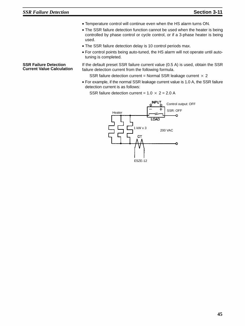
45
• Temperature control will continue even when the HS alarm turns ON.
• The SSR failure detection function cannot be used when the heater is beingcontrolled by phase control or cycle control, or if a 3-phase heater is beingused.
• The SSR failure detection delay is 10 control periods max.
• For control points being auto-tuned, the HS alarm will not operate until auto-tuning is completed.
If the default preset SSR failure current value (0.5 A) is used, obtain the SSRfailure detection current from the following formula.
SSR failure detection current = Normal SSR leakage current 2
• For example, if the normal SSR leakage current value is 1.0 A, the SSR failuredetection current is as follows:
SSR failure detection current = 1.0 2 = 2.0 A
Heater
1 kW x 3
Control output: OFF
200 VAC
E5ZE-12
SSR: OFF
SSR Failure DetectionCurrent Value Calculation
SSR Failure Detection Section 3-11

47
SECTION 4Troubleshooting
This section describes the troubleshooting procedure and possible errors and remedies when the E5ZE is not operating prop-erly. When performing troubleshooting follow the order in which information is provided in this section.
4-1 Troubleshooting Procedure 48. . . . . . . . . . . . . . . . . . . . . . . . . . . . . . . . . . . . . . . . . . . . . . . . . 4-2 Communications Errors 49. . . . . . . . . . . . . . . . . . . . . . . . . . . . . . . . . . . . . . . . . . . . . . . . . . . . 4-3 Temperature Sensing Errors 51. . . . . . . . . . . . . . . . . . . . . . . . . . . . . . . . . . . . . . . . . . . . . . . . . 4-4 Temperature Control Errors 53. . . . . . . . . . . . . . . . . . . . . . . . . . . . . . . . . . . . . . . . . . . . . . . . . 4-5 Output Errors 55. . . . . . . . . . . . . . . . . . . . . . . . . . . . . . . . . . . . . . . . . . . . . . . . . . . . . . . . . . . . 4-6 HB Alarm and HS Alarm Errors 57. . . . . . . . . . . . . . . . . . . . . . . . . . . . . . . . . . . . . . . . . . . . .

48
4-1 Troubleshooting Procedure
If the E5ZE has an error, refer to the following items to find the possible cause ofthe error and take corrective measures.
1, 2, 3... 1. Indicators
Check the operating status of the E5ZE using the indicators.
If the ERR indicator is lit, turn the E5ZE OFF and ON. If the ERR indicator isnot lit after the E5ZE is turned ON, it may mean that the E5ZE is being in-fluenced by noise. Find the source of the noise and provide adequateprotection against it.
2. Switch, Selectors, and Wiring
Check if the switch and selector settings of the E5ZE, the wiring of the E5ZEand devices connected to the E5ZE are correct.
a) Power Supply
• Check that the power supply connected to the E5ZE is turned ON.
• Check whether the supply voltage at the power supply terminals iswithin the allowable voltage range of the E5ZE.
b) Switch and Selectors
Check that the switch and selectors of the E5ZE are correctly set accord-ing to the system.
c) Wiring
• Check that the terminals and connectors are wired together correctly.
• Check that the terminal block wiring is correct.
• Check that the polarity of each wire connected to the E5ZE is correct.
• Check if any wire is disconnected.
• Check if a wire or cable is cut or short-circuited.
• Check that the wiring-reduction devices connected to the E5ZE are thecorrect designated ones.
d) Communications Conditions
Check that the communications conditions of the E5ZE are compatiblewith the host device connected to the E5ZE.
Check the above items and remedy any problems listed above. If the errorpersists after error processing, perform further checks through communica-tions.
3. Checking through Communications
• Check the end code and error code with the response returned from theE5ZE.
• Check the status of the E5ZE with the Status Read Command.
• Check if the functions used with the E5ZE have any operating restrictions.
• Check if the set data items of the communication commands used for theE5ZE are correct.
Troubleshoot problems on the basis of the data read with the E5ZE.
Troubleshooting Procedure Section 4-1

49
4. Troubleshooting Based on Error Symptoms
If the cause of the error is still unknown after checking all the previously men-tioned items, find the cause by isolating the symptoms of the error while re-ferring to the tables in this section, and remedy accordingly.
4-2 Communications Errors
Communications Not Possible or No ResponseProbable cause Remedy
Communicationsconditions
Baud rate of the E5ZE is different from that ofthe host device.
Set the same rate.
Communications method of the E5ZE is differentfrom that of the host device.
Set the host device’s communications conditionsas follows:
• Stop bits: 2
• Parity: Even
• Bit length: 7 bitsConnections Excessive number of E5ZE Units are connected
in parallel.Do not connect an excessive number of E5ZEUnits.
• Do not connect the host device directly to morethan one E5ZE through RS-232Ccommunications.
• The number of E5ZE Units that can beconnected to the host device for RS-422 orRS-485 communications is 16 max.
Transmission path is too long. The transmission path must be within thepermissible range.
• The maximum RS-232C transmission path is15 m.
• The maximum RS-422 or RS-485 transmissionpath is 500 m in total.
Same unit number has been assigned more thanonce on the same transmission path.
Make sure that different numbers are assignedto all the E5ZE Units that communicate with thehost device.
Communications data error due to ambientnoise.
• Move the communications cable away from thesource of noise.
• Use shielded communication cables.
• Use an Optical Interface.
• Write a program that makes it possible for thehost device to detect a response error for anycommand that the host device transmits and tore-transmit it again.
Mistake in the use of the Optical Interface andLink Adapter Units.
Refer to the datasheets of the Optical Interfaceand Link Adapter Units used.
Communications Errors Section 4-2
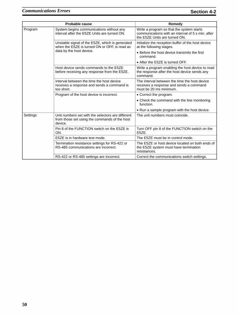
50
Probable cause RemedyProgram System begins communications without any
interval after the E5ZE Units are turned ON.Write a program so that the system startscommunications with an interval of 5 s min. afterthe E5ZE Units are turned ON.
Unstable signal of the E5ZE, which is generatedwhen the E5ZE is turned ON or OFF, is read asdata by the host device.
Initialize the reception buffer of the host deviceat the following stages.
• Before the host device transmits the firstcommand.
• After the E5ZE is turned OFF.
Host device sends commands to the E5ZEbefore receiving any response from the E5ZE.
Write a program enabling the host device to readthe response after the host device sends anycommand.
Interval between the time the host devicereceives a response and sends a command istoo short.
The interval between the time the host devicereceives a response and sends a commandmust be 20 ms minimum.
Program of the host device is incorrect. • Correct the program.
• Check the command with the line monitoringfunction.
• Run a sample program with the host device.Settings Unit numbers set with the selectors are different
from those set using the commands of the hostdevice.
The unit numbers must coincide.
Pin 8 of the FUNCTION switch on the E5ZE isON.
Turn OFF pin 8 of the FUNCTION switch on theE5ZE.
E5ZE is in hardware test mode. The E5ZE must be in control mode.
Termination resistance settings for RS-422 orRS-485 communications are incorrect.
The E5ZE or host device located on both ends ofthe E5ZE system must have terminationresistances.
RS-422 or RS-485 settings are incorrect. Correct the communications switch settings.
Communications Errors Section 4-2

51
4-3 Temperature Sensing Errors
Temperature Sensing Not Possible or AbnormalProbable cause Remedy
Connections Polarity or wiring of a temperature sensor isincorrect.
Correct the wiring of the temperature sensor.
Temperature sensor is not an applicable one. Replace the temperature sensor with anapplicable one.
Leads of a temperature sensor are disconnected,short-circuited, or deteriorated.
Replace the temperature sensor.
Temperature sensors are not used. Use temperature sensors.
Thermocouple does not use applicablecompensating conductors.
• Replace the thermocouple with anotherthermocouple with long leads.
• Connect applicable compensating conductorsfor the thermocouple.
Thermocouple is connected to the E5ZE with adevice using a metal that is different in type fromthe metal of the thermocouple or that of thecompensating conductors.
Connect a thermocouple-dedicated device be-tween the thermocouple and the E5ZE.
A screw of the terminal block of the E5ZE isloosened and improper contact is resulting.
Tighten the screw.
Leads or compensating conductors of athermocouple are too long and leads orcompensating conductors have resistance.
• Use sufficiently thick compensating conductors.
• Change the location of the thermocouple so thatthe length of the leads or compensatingconductors can be shortened.
The resistance of the conductors for the 3terminals is different from the resistance of thetemperature sensor connected to the E5ZE.
Use conductors that are the same in resistancefor the two B terminals and the A terminal.
Installation Noise is affecting the E5ZE. • Separate the E5ZE from the source of thenoise.
• Connect a surge absorber or noise filter to thedevice generating the noise.
Inductive noise generated from power lines isaffecting the leads of a temperature sensor.
• Separate the leads from the power lines.
• Wire the leads in a separate conduit or duct.
• Do not wire the leads alongside power lines.
• Shorten the leads.
• Shield the leads.
Thermal response of a temperature sensorconnected to the E5ZE is slow because thetemperature sensor is located far from thetemperature controlling position of the E5ZE.
Locate the tip of the protective tubing of thetemperature sensor at the temperature controllingposition.
Ambient operating temperature of the E5ZE is notwithin the allowable ambient operatingtemperature range of the E5ZE.
The ambient operating temperature range of theE5ZE must be between 0°C and 55°C.
Radio transmitter is being used near the E5ZE. Shield the E5ZE.
E5ZE is affected by heat radiation from PeripheralDevices and the temperature of the terminal blockof the E5ZE is not even.
Install the E5ZE in a location where it will not beaffected by heat radiation.
Terminal block of the E5ZE is affected by wind. Protect the terminal block of the E5ZE againstwind.
Temperature Sensing Errors Section 4-3

52
Probable cause RemedySettings Selector settings for the input type of temperature
sensor are incorrect.Correct the INPUT selector setting.
Celsius-Fahrenheit designation of the E5ZE isincorrect.
Correct the FUNCTION switch setting.
The process value appears to be incorrect due tothe input shift setting.
E5ZE FUNCTION switch is not set correctly forthe E5ZD-SDL Setting Display Unit connected tothe E5ZE.
Set the input shift to 0.0.
Correct the FUNCTION switch setting.
Data setting unit is incorrect. Change the program of the host device.
Program of the host device is incorrect. Change the program of the host device.
Operation Temperature sensor input terminals of the E5ZEthermocouple input model have beenshort-circuited.
Connect a thermocouple to the temperaturesensor input terminals.
Temperature sensor connected to the E5ZE hasbeen replaced or the switch or selector settings ofthe E5ZE have been changed while the power isON.
Turn OFF the power to the E5ZE, and then turnON again.
Simple Method for Checking Temperature SensorsPlatinum Resistance Thermometer
1, 2, 3... 1. Connect a 100-Ω resistor between the A and B temperature sensor inputterminals and short-circuit the B terminals.
2. If the temperature sensed by the E5ZE is 0.0°C or 32.0°F, the E5ZE is oper-ating normally.
Thermocouple
1, 2, 3... 1. Short-circuit the temperature sensor input terminals of the E5ZE.
2. If the E5ZE senses the temperature of the terminal block of the E5ZE, theE5ZE is operating normally.
Temperature Sensing Errors Section 4-3

53
4-4 Temperature Control Errors
Temperature Does Not RiseProbable cause Remedy
Connections Process value of the E5ZE is abnormal. Refer to 4-3 Temperature Sensing Errors forappropriate troubleshooting.
Load is not connected to the control outputterminal of the E5ZE.
Connect a load.
Polarity or wiring of a load is incorrect. Correct the wiring of the load.
A screw of the terminal block of the E5ZE isloosened and improper contact is resulting.
Tighten the screw.
Power is not supplied to heaters. Supply power to the heaters.
Heaters are burnt out or have deteriorated. Replace the heaters.
Heat capacity of the heater is too small. • Replace the heater with one having a largerheat capacity.
• If more than one heater is used and some areburnt out, replace the heaters.
Overheating prevention device for the E5ZE isoperating.
The set value of the overheating preventiondevice must be larger than the set value of theE5ZE.
Settings E5ZE is in reverse operation mode, instead ofdirect operation mode, or vice versa.
Correct the operation mode setting.
PID constants of the E5ZE are incorrect. • Execute auto-tuning.
• Set the PID constants of the E5ZE toappropriate values.
E5ZE has not started temperature control. Start the temperature control.
Control output value of the E5ZE does notincrease because of the restrictions of the setoutput limit value.
• Set the output limit value of the E5ZE to anappropriate value.
Control output value of the E5ZE does notincrease because of the restrictions of the setoutput change rate limit.
• Disable the output change rate limit function ofthe E5ZE by setting to 0000.
• Set the output change rate limit of the E5ZE toan appropriate value.
Cooling fan is operating. Turn OFF the cooling fan.
Temperature Control Errors Section 4-4

54
Process Value Exceeds Set PointProbable cause Remedy
Connections Process value of the E5ZE is abnormal. Refer to 4-3 Temperature Sensing Errors forappropriate troubleshooting.
Load is connected to the incorrect control point ofthe E5ZE and is controlling the heaters with thecontrol output of the incorrect control point.
Correct the wiring of the load.
Relay driven by control output has contact weld. Replace the relay.
SSR is short-circuited. Replace the SSR.
SSR leakage current is flowing into the heaters. Connect a bleeder resistance to the SSR toprevent operation with the SSR leakage current.
Settings E5ZE is in reverse operation mode, instead ofdirect operation mode, or vice versa.
Correct the operation mode setting.
PID constants of the E5ZE are incorrect. • Execute auto-tuning.
• Set the PID constants of the E5ZE to the valuessuitable to the system.
Control output value of the E5ZE does notincrease because of the restrictions of the setoutput limit value.
• Set the output limit value of the E5ZE to anappropriate value.
Control output value of the E5ZE does notincrease because of the restrictions of the setoutput change rate limit value.
• Disable the output change rate limit function ofthe E5ZE by setting to 0000.
• Set the output change rate limit value of theE5ZE to an appropriate value.
E5ZE is outputting in manual operation. Interrupt the manual operation of the E5ZE.
Operation Controlled object is radiating heat. Execute heating and cooling control.
Controlled object is influenced by largeovershooting.
Refer to the following table regardingovershooting and undershooting for appropriatetroubleshooting.
Overshooting or UndershootingProbable cause Remedy
Connections Process value of the E5ZE is abnormal. Refer to 4-3 Temperature Sensing Errors forappropriate troubleshooting.
General-purpose temperature sensor with slowthermal response characteristics is being used tosense a controlled object with quick thermalresponse characteristics.
Change to a sheath-type temperature sensor.
Settings E5ZE has a narrow proportional band and smallP constant.
• Increase the P constant keeping within therange where the response delay caused by theP constant can be allowed.
• Execute auto-tuning.
E5ZE has a short integral time or small Iconstant.
• Increase the I constant keeping within the rangewhere the response delay caused by the Iconstant can be allowed.
• Execute auto-tuning.
E5ZE has a short derivative time or small Dconstant.
• Increase the D constant keeping within therange where the D constant will not have anundesirable influence on temperature stability.
• Execute auto-tuning.
E5ZE is executing ON and OFF control with a Pconstant of 0.
Execute P or PID control.
Control period is too long when the E5ZE controlsthe temperature of an object with quick thermalresponse characteristics.
Shorten the control period.
Dead band instead of an overlap band is set withthe E5ZE in heating and cooling controloperation.
Set the overlap band of the E5ZE.
Temperature Control Errors Section 4-4

55
HuntingFor troubleshooting problems with connections and settings, refer to the sameprobable causes and remedies as provided for overshooting and undershoot-ing.
Probable cause Remedy
Operation Heat capacity of a heater controlling thetemperature of an object is too large for theobject.
Use a heater with a heat capacity suited to theobject.
Heat capacity of a controlled object changes dueto periodical external disturbances.
Take appropriate measures to prevent theperiodical external disturbances.
E5ZE is executing auto-tuning. Hunting will not occur if auto-tuning is completed.
4-5 Output Errors
Control Output or Alarm Output Does Not Turn ONProbable cause Remedy
Connections Process value of the E5ZE is abnormal. Refer to 4-3 Temperature Sensing Errors forappropriate troubleshooting.
Polarity of the load or connected terminals arewired incorrectly.
Connectors are not connected to the correctterminal blocks.
• Correct the wiring.
• Connect the connectors correctly.
Load exceeding the output ratings of the E5ZE isconnected.
• Connect a load that does not exceed the outputratings to the E5ZE.
• Request repair of the E5ZE if it ismalfunctioning.
Load power supply is not connected to alarmoutput or cooling control output.
Provide a power supply satisfying the outputratings of the E5ZE and suitable for the load.
Polarity of the load power supply for alarm outputor cooling control output is incorrect.
Correct the wiring.
Power is not being supplied to thewiring-reduction device.
Supply power required to satisfy the ratings of thedevice.
The wiring-reduction device is not connected tothe E5ZE using Connecting Cable.
Use the Connecting Cable specified in 2-6 WiringCT Inputs and Control/Alarm Outputs.
Output Errors Section 4-5
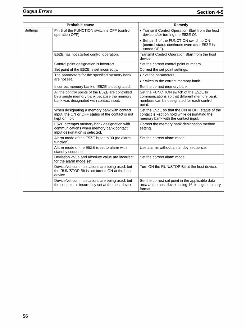
56
Probable cause RemedySettings Pin 5 of the FUNCTION switch is OFF (control
operation OFF).• Transmit Control Operation Start from the host
device after turning the E5ZE ON.
• Set pin 5 of the FUNCTION switch to ON(control status continues even after E5ZE isturned OFF).
E5ZE has not started control operation. Transmit Control Operation Start from the hostdevice.
Control point designation is incorrect. Set the correct control point numbers.
Set point of the E5ZE is set incorrectly. Correct the set point settings.
The parameters for the specified memory bankare not set.
• Set the parameters.
• Switch to the correct memory bank.
Incorrect memory bank of E5ZE is designated. Set the correct memory bank.
All the control points of the E5ZE are controlledby a single memory bank because the memorybank was designated with contact input.
Set the FUNCTION switch of the E5ZE tocommunications so that different memory banknumbers can be designated for each controlpoint.
When designating a memory bank with contactinput, the ON or OFF status of the contact is notkept on hold.
Set the E5ZE so that the ON or OFF status of thecontact is kept on hold while designating thememory bank with the contact input.
E5ZE attempts memory bank designation withcommunications when memory bank contactinput designation is selected.
Correct the memory bank designation methodsetting.
Alarm mode of the E5ZE is set to 00 (no alarmfunction).
Set the correct alarm mode.
Alarm mode of the E5ZE is set to alarm withstandby sequence.
Use alarms without a standby sequence.
Deviation value and absolute value are incorrectfor the alarm mode set.
Set the correct alarm mode.
DeviceNet communications are being used, butthe RUN/STOP Bit is not turned ON at the hostdevice.
Turn ON the RUN/STOP Bit at the host device.
DeviceNet communications are being used, butthe set point is incorrectly set at the host device.
Set the correct set point in the applicable dataarea at the host device using 16-bit signed binaryformat.
Output Errors Section 4-5
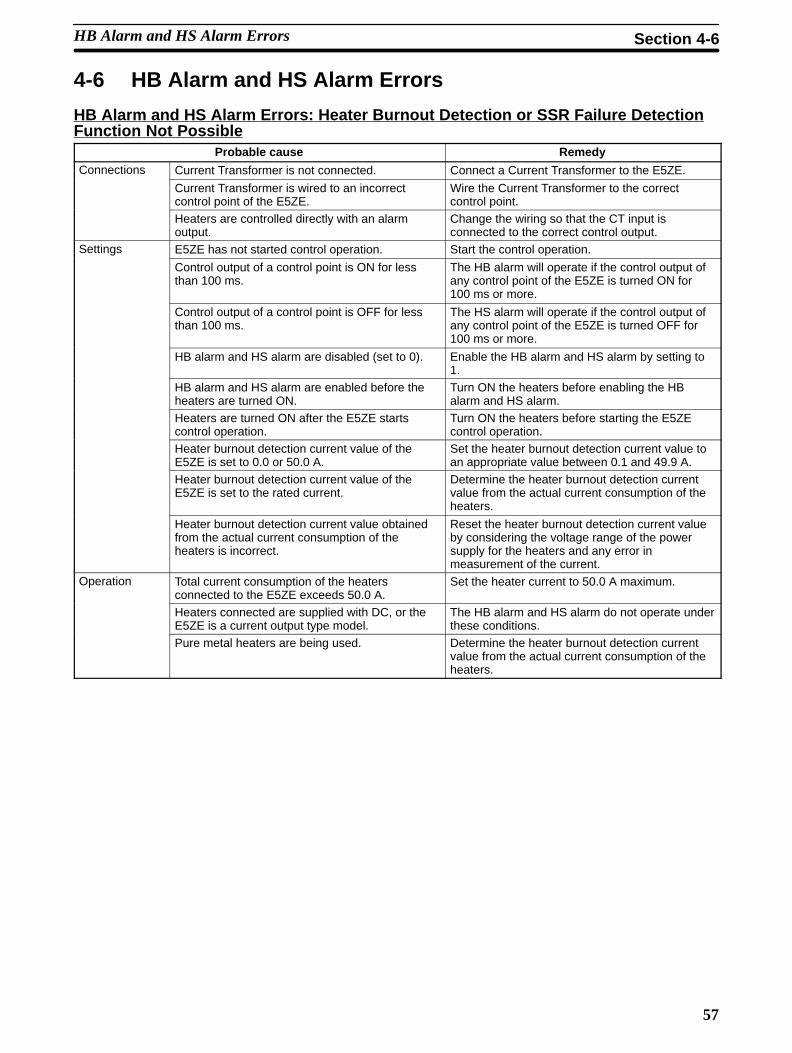
57
4-6 HB Alarm and HS Alarm Errors
HB Alarm and HS Alarm Errors: Heater Burnout Detection or SSR Failure DetectionFunction Not Possible
Probable cause Remedy
Connections Current Transformer is not connected. Connect a Current Transformer to the E5ZE.
Current Transformer is wired to an incorrectcontrol point of the E5ZE.
Wire the Current Transformer to the correctcontrol point.
Heaters are controlled directly with an alarmoutput.
Change the wiring so that the CT input isconnected to the correct control output.
Settings E5ZE has not started control operation. Start the control operation.
Control output of a control point is ON for lessthan 100 ms.
The HB alarm will operate if the control output ofany control point of the E5ZE is turned ON for100 ms or more.
Control output of a control point is OFF for lessthan 100 ms.
The HS alarm will operate if the control output ofany control point of the E5ZE is turned OFF for100 ms or more.
HB alarm and HS alarm are disabled (set to 0). Enable the HB alarm and HS alarm by setting to1.
HB alarm and HS alarm are enabled before theheaters are turned ON.
Turn ON the heaters before enabling the HBalarm and HS alarm.
Heaters are turned ON after the E5ZE startscontrol operation.
Turn ON the heaters before starting the E5ZEcontrol operation.
Heater burnout detection current value of theE5ZE is set to 0.0 or 50.0 A.
Set the heater burnout detection current value toan appropriate value between 0.1 and 49.9 A.
Heater burnout detection current value of theE5ZE is set to the rated current.
Determine the heater burnout detection currentvalue from the actual current consumption of theheaters.
Heater burnout detection current value obtainedfrom the actual current consumption of theheaters is incorrect.
Reset the heater burnout detection current valueby considering the voltage range of the powersupply for the heaters and any error inmeasurement of the current.
Operation Total current consumption of the heatersconnected to the E5ZE exceeds 50.0 A.
Set the heater current to 50.0 A maximum.
Heaters connected are supplied with DC, or theE5ZE is a current output type model.
The HB alarm and HS alarm do not operate underthese conditions.
Pure metal heaters are being used. Determine the heater burnout detection currentvalue from the actual current consumption of theheaters.
HB Alarm and HS Alarm Errors Section 4-6
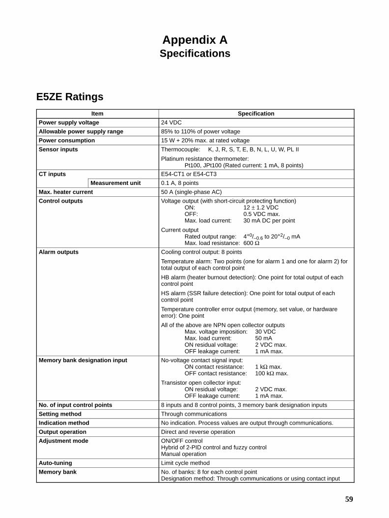
59
Appendix ASpecifications
E5ZE RatingsItem Specification
Power supply voltage 24 VDC
Allowable power supply range 85% to 110% of power voltage
Power consumption 15 W + 20% max. at rated voltage
Sensor inputs Thermocouple: K, J, R, S, T, E, B, N, L, U, W, PL II
Platinum resistance thermometer:Pt100, JPt100 (Rated current: 1 mA, 8 points)
CT inputs E54-CT1 or E54-CT3
Measurement unit 0.1 A, 8 points
Max. heater current 50 A (single-phase AC)
Control outputs Voltage output (with short-circuit protecting function)ON: 12 ± 1.2 VDCOFF: 0.5 VDC max.Max. load current: 30 mA DC per point
Current outputRated output range: 4+0/–0.6 to 20+2/–0 mAMax. load resistance: 600 Ω
Alarm outputs Cooling control output: 8 points
Temperature alarm: Two points (one for alarm 1 and one for alarm 2) fortotal output of each control point
HB alarm (heater burnout detection): One point for total output of eachcontrol point
HS alarm (SSR failure detection): One point for total output of eachcontrol point
Temperature controller error output (memory, set value, or hardwareerror): One point
All of the above are NPN open collector outputsMax. voltage imposition: 30 VDCMax. load current: 50 mAON residual voltage: 2 VDC max.OFF leakage current: 1 mA max.
Memory bank designation input No-voltage contact signal input:ON contact resistance: 1 kΩ max.OFF contact resistance: 100 kΩ max.
Transistor open collector input:ON residual voltage: 2 VDC max.OFF leakage current: 1 mA max.
No. of input control points 8 inputs and 8 control points, 3 memory bank designation inputs
Setting method Through communications
Indication method No indication. Process values are output through communications.
Output operation Direct and reverse operation
Adjustment mode ON/OFF controlHybrid of 2-PID control and fuzzy controlManual operation
Auto-tuning Limit cycle method
Memory bank No. of banks: 8 for each control pointDesignation method: Through communications or using contact input

Appendix ASpecifications
60
Item Specification
Ambient operating temperature –10 to 55 °C (0 to 55 °C for the E5ZE-8D1B)(with no icing or condensation)
Ambient operating humidity 35% to 85% RH
Storage temperature –25 to 65 °C (with no icing or condensation)
Storage humidity 35% to 95% (with no condensation)
Communications Ratings
Serial CommunicationsCommunications interface RS-232C RS-422 RS-485
Transmission method Serial communications
Terminal Data processing terminal
Communications method Half-duplex
Connecting method 25-pin D-sub connector 5-pole terminal block (with M3 screws)
Transmission line configuration 3-wire 4-wire 2-wire
Transmission line type Direct line Multi-drop line
Synchronization method Start-stop synchronization (asynchronous)
Baud rate 2,400/4,800/9,600/19,200 bps
Transmission code ASCII
No. of stop bits 2
Parity Even parity
Character length 7 bits
Error detection Vertical parity and FCS (frame check sequence)
Communications unit no. 0 to F (hexadecimal)
Transmission and receptionswitching time
--- 20 ms max.
Max. cable length 15 m 500 m in total
No. of controllers connected inparallel
--- 16 (excluding host system)
DeviceNet CommunicationsItem Specification
Power supply voltage 24 VDC
Allowable voltage fluctuation range 11 to 25 VDC (supplied through communications connector)
Current consumption 24 VDC at 45 mA max.
No. of Remote I/O words 14 input words, 9 output words
Message communications function FINS messages

Appendix ASpecifications
61
E5ZE Characteristics
Item Specification
Measurementrange
–20°C (lower limit of the setting range) to 20°C (upper limit of the setting range)–40°F (lower limit of the setting range) to 40°F (upper limit of the setting range)
Setting Setting unit 1 0.1range Celsius Fahrenheit Celsius Fahrenheit
(See note 2.)Ther- K –200 to 1,300°C –300 to 2,300°F –200.0 to 1,300.0°C –300.0 to 2,300.0°Fmocou- J –100 to 850°C –100 to 1,500°F –100.0 to 850.0°C –100.0 to 1,500.0°Fple
R 0 to 1,700°C 0 to 3,000°F 0.0 to 1,700.0°C 0.0 to 3,000.0°FS 0 to 1,700°C 0 to 3,000°F 0.0 to 1,700.0°C 0.0 to 3,000.0°FT –200 to 400°C –300 to 700°F –200.0 to 400.0°C –300.0 to 700.0°FE 0 to 600°C 0 to 1,100°F 0.0 to 600.0°C 0.0 to 1,100.0°FB 100 to 1,800°C 300 to 3,000°F 100.0 to 1,800.0°C 300.0 to 3,000.0°FN 0 to 1,300°C 0 to 2,300°F 0.0 to 1,300.0°C 0.0 to 2,300.0°FL –100 to 850°C –100 to 1,500°F –100.0 to 850.0°C –100.0 to 1,500.0°FU –200 to 400°C –300 to 700°F –200.0 to 400.0°C –300.0 to 700.0°FW/Re5-26 0 to 2,300°C 32 to 4,100°F 0.0 to 2,300.0°C 0.0 to 4,100.0°FPL-II 0 to 1,300°C 0 to 2,300°F 0.0 to 1,300.0°C 0.0 to 2,300.0°F
Plati-numresis-
Pt 100 –100 to 500°C –100 to 900°F –100.0 to 500.0°C –100.0 to 900.0°F
tancether-mome-ter
JPt 100 –100 to 500°C –100 to 900°F –100.0 to 500.0°C –100.0 to 900.0°F
Measurementaccuracy
Thermocouple:±0.3% of the process value or ±2°C, whichever is larger ±1 digit max.±0.3% of the process value or ±3.6°F, whichever is larger ±1 digit max.
Platinum resistance thermometer:±0.3% of the process value or ±0.8°C, whichever is larger ±1 digit max.±0.3% of the process value or ±1.5°F, whichever is larger ±1 digit max.
Settingaccuracy
There is no difference between the setting accuracy and measurement accuracy.
Guaranteedsetting accuracyrange
Same as the setting range.
Influence ofconductorresistance
Thermocouple: ±0.1°C/Ω or ±0.2°F/Ω max.Platinum resistance thermometer: ±1.0°C/Ω or ±1.8°F/Ω max. per line
Input shift –99.9 to 99.9°C/°F (in units of 0.1°C/°F)
Hysteresis 0.0 to 99.9°C/°F for ON/OFF control only (in units of 0.1°C/°F)
Coolingcoefficient
0.0 to 10.0 (in units of 0.1)
Proportionalband(P constant)
0.0° to 999.9°C/°F (in units of 0.1°C/°F)Cooling proportional band: Proportional band x Cooling factor
Integral time(I constant)
0 to 3,999 s (in units of 1 s) (cannot be set for heating and cooling independently)
Derivative time(D constant)
0 to 3,999 s (in units of 1 s)(cannot be set for heating and cooling independently)
Control period 1 to 99 s (in units of 1 s)Cooling control period: 1 to 99 s (in units of 1 s)
Sampling period 200 ms for 8 control points

Appendix ASpecifications
62
Item Specification
Deadband/overlapband
–999 to 999°C/°F (in units of 1°C/°F)
Upper-limitoutput value
ON/OFF pulse type: (Lower-limit output value + 0.1)% to 100.0% (in units of 0.1%)Linear output type: (Lower-limit output value + 0.1)% to 105.0% (in units of 0.1%)
Lower-limitoutput value
ON/OFF pulse type: 0.0% to (Upper-limit output value – 0.1)% (in units of 0.1%)Linear output type: –5.0% to (Upper-limit output value – 0.1)% (in units of 0.1%)
Output valuechange ratelimit
0.0% to 100.0% per sampling period (200 ms approx.) in units of 0.1%
Alarm Setting unit 1 0.1 (See note 2)outputsettingrange
Alarmmode
Upper- andlower-limit(See note 1)
0° to 9,999°C/°F 0.0° to 9,999.9°C/°F
Upper-limit(See note 1)
–999° to 9,999°C/°F –999.9° to 9,999.9°C/°F
Lower-limit –999° to 9,999°C/°F –999.9° to 9,999.9°C/°FUpper- andlower-limitrange
0° to 9,999°C/°F 0.0° to 9,999.9°C/°F
Absolute-value up-per-limit(See note 1)
–999° to 9,999°C/°F –999.9° to 9,999.9°C/°F
Absolute-value lower-limit (Seenote 1)
–999° to 9,999°C/°F –999.9° to 9,999.9°C/°F
HB and HSalarm
–999° to 9,999°C/°F –999.9° to 9,999.9°C/°F
CT input measurement range 0.0 to 55.0 A AC(in units of 0.1 A)
CT input measurement accu-racy
±5% FS ± 1 digit max. (between 0.0 to 50.0 A)
HB and HS alarm setting range 0.0 to 50.0 A (in units of 0.1 A)
HB and HS alarm setting accu-racy
There is no difference between the CT input measurement accuracy and HB and HSalarm setting accuracy.
HB alarm min. detection ONtime
Control output must be continuously ON for 100 ms min.
HS alarm min. detection OFFtime
Control output must be continuously OFF for 100 ms min.
Fuzzy strength 0% to 99% (in units of 1%)
Fuzzy scale 1 0.2 to 999.9°C/°F (in units of 0.1°C/°F)
Fuzzy scale 2 0.02 to 99.99°C/s or °F/s (in units of 0.01°C/s or °F/s)
Insulation resistance 20 MΩ min. between the FG terminal and all input terminals (at 500 VDC)
Dielectric strength 500 VAC for 1 minute between the FG terminal and all input terminals
Vibration resistance Malfunction:Vibration frequency: 10 to 55 HzAcceleration: 15 m/s2
Direction and time: 8 min each in X, Y, and Z directions
Destruction:Vibration frequency: 10 to 55 HzAcceleration: 20 m/s2
Direction and time: 8 min each in X, Y, and Z directions

Appendix ASpecifications
63
Item Specification
Shock resistance Malfunction:Max. acceleration: 150 m/s2
Direction: 3-axis, 6 directionsTimes: 18 times in total
Destruction:Max. acceleration: 200 m/s2
Direction: 3-axis, 6 directionsTimes: 18 times in total
Enclosure rating IP00
Dimensions E5ZE-8 -E (without casing): 169.5 x 192 x 58 mm
E5ZE-8 B-E (with casing): 173.5 x 230 x 65 mm
E5ZE-8 D1B (DeviceNet): 173.5 x 253 x 65 mm
Set value backup Lithium battery
Set value backup period 10 years min. provided that the ambient temperature is within the normal room tempera-ture
Weight Without casing: Approx. 900 g With casing: Approx. 1,700 g (including 2 mounting brackets)
Note 1. These alarm mode settings include the standby sequence.
2. When DeviceNet is used to set the alarm settings, the upper limit is 3,000.0 °C/°F (in units of 0.1)
3. The applicable standards for the temperature sensor input types are as follows:
K, J, T, E, R, S, B: JIS C1602-1981
L: Fe-CuNi, DIN 43710-1985
U: Cu-CuNi, DIN 43710-1985
N: Nicrosil-NisiL, IEC584-1, 1977; Amendment No. 1, 1989
W: W5Re/W26Re, ASTM E988-1990
PL II: According to PLATINEL II Electromotive Force Table by ENGELHARD
JPt100: JIS C 1604-1989, JIS C1606-1989
Pt100: JIS C 1604-1989, JIS C1606-1989 IEC 751
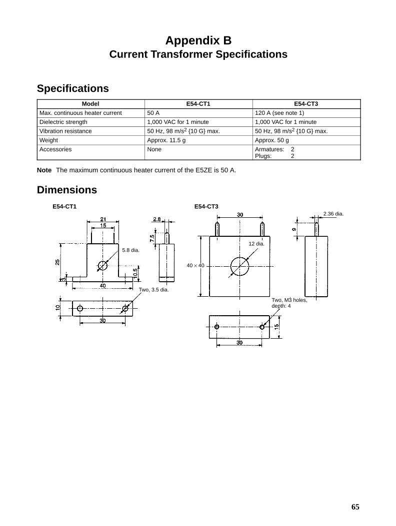
65
Appendix BCurrent Transformer Specifications
SpecificationsModel E54-CT1 E54-CT3
Max. continuous heater current 50 A 120 A (see note 1)
Dielectric strength 1,000 VAC for 1 minute 1,000 VAC for 1 minute
Vibration resistance 50 Hz, 98 m/s2 10 G max. 50 Hz, 98 m/s2 10 G max.
Weight Approx. 11.5 g Approx. 50 g
Accessories None Armatures: 2Plugs: 2
Note The maximum continuous heater current of the E5ZE is 50 A.
Dimensions
5.8 dia.
Two, 3.5 dia.
12 dia.
2.36 dia.
Two, M3 holes,depth: 4
E54-CT1 E54-CT3
40 × 40
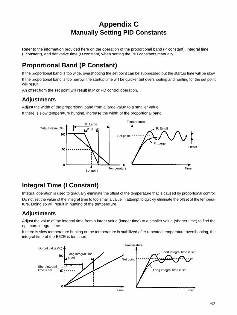
67
Appendix CManually Setting PID Constants
Refer to the information provided here on the operation of the proportional band (P constant), integral time (I constant), and derivative time (D constant) when setting the PID constants manually.
Proportional Band (P Constant)If the proportional band is too wide, overshooting the set point can be suppressed but the startup time will be slow.
If the proportional band is too narrow, the startup time will be quicker but overshooting and hunting for the set pointwill result.
An offset from the set point will result in P or PD control operation.
AdjustmentsAdjust the width of the proportional band from a large value to a smaller value.
If there is slow temperature hunting, increase the width of the proportional band.
Output value (%)
TemperatureSet point
P: Large
P: Small
Temperature
Set point
P: Small
P: LargeOffset
Time
Integral Time (I Constant)Integral operation is used to gradually eliminate the offset of the temperature that is caused by proportional control.
Do not set the value of the integral time to too small a value in attempt to quickly eliminate the offset of the tempera-ture. Doing so will result in hunting of the temperature.
AdjustmentsAdjust the value of the integral time from a larger value (longer time) to a smaller value (shorter time) to find theoptimum integral time.
If there is slow temperature hunting or the temperature is stabilized after repeated temperature overshooting, theintegral time of the E5ZE is too short.
Output value (%)
Short integraltime is set.
Long integral timeis set.
Time
Temperature
Short integral time is set.
Long integral time is set.
Set point
Time

Appendix CManually Setting PID Constants
68
Derivative Time (D Constant)Derivative operation is used to quickly return the temperature to its original value by providing a large output valueeven if there is radical external disturbance.
Do not set the derivative time to be too long, otherwise a large temperature output value will continue to be outputand the temperature will not be stabilized. At this time, hunting of the temperature, with a cycle shorter than huntingcaused by incorrect proportional band or integral time values, will result.
AdjustmentAdjust the value of the derivative time from the larger value (longer time) to a smaller value (shorter time) to find theoptimum derivative time.
If there is hunting of the temperature with a short cycle, the derivative time may be set too long and the temperaturecontrol response may be too fast.
Output value (%)
Short derivativetime is set.
Long derivative time is set.
Time
Temperature
Set point
Long derivative time is set.
Short derivative time is set.
Time
Fuzzy ConstantsFuzzy constants are normally adjusted automatically. If, however, the results of automatic adjustment are not sat-isfactory, or the response to external disturbance needs further improvement, the fuzzy constants can be manuallyadjusted. The following flowchart shows how to manually adjust fuzzy constants.
Check external distur-bance response
Adjust fuzzy strength andfuzzy scale 1
Check adjustmentresults
Adjustment completeAdjust fuzzy scale 2
Adjust fuzzy scale 2 only when fuzzy strength and fuzzy scale 1 adjustments are unsatisfactory.

Appendix CManually Setting PID Constants
69
Increasing Fuzzy Strength
Excessive overshooting
Excessive undershooting
ExternaldisturbanceTemperature
Set point
Time
Smaller overshooting
Smaller undershooting
TemperatureExternaldisturbance
Time
Set point
Increasing Fuzzy Scale 1
Excessive undershooting
ExternaldisturbanceTemperature
Set point
Time
Smaller undershooting
Temperature
Excessive overshootingSmaller overshooting
Vibration Decreased vibration
Externaldisturbance
Set point
Time
Reducing Fuzzy Scale 1
Excessive undershooting
ExternaldisturbanceTemperature
Set point
Time
Smaller overshooting
Temperature
Slow stabilization Quick stabilization
Externaldisturbance
Time
Set point
The following table shows the tendency of external disturbance response when fuzzy constants are adjusted.
Fuzzy constants External disturbance response
Excessivevalue
Oscillation Stabilizationtime
Fuzzy strength Larger Decreases Increases ---
Smaller Increases Decreases
Fuzzy scale 1 Larger Increases Decreases Longand fuzzyscale 2 Smaller Decreases Increases Short
Excessive value: Overshooting or undershooting
Oscillation: Hunting

71
Appendix DSaving Data
FunctionAll temperature control data set with the E5ZE using serial communications will be deleted if the E5ZE is turnedOFF without saving the temperature control data.
Execute the Memory Write (WE) command to save temperature control data set with the E5ZE.
Data set using DeviceNet communications will not be deleted even if the power is turned OFF.
SaveUse the following procedure to save the temperature control data set with the E5ZE in the memory.
1, 2, 3... 1. Transmit the WE command to the E5ZE.
2. After transmitting the WE command, confirm that the response transmittedfrom the E5ZE is normal.
If the E5ZE is turned OFF before the E5ZE completes transmitting the response of the WE command, the temper-ature control data set with the E5ZE may not be saved and when the power is turned ON again a memory error mayoccur.
Confirming Saved DataTransmit the Status Read (RX) command to read the operating status of the E5ZE. Check the status code of theresponse to confirm whether the data has been saved.
Data ProcessingThe following shows how the temperature control data set with the E5ZE is processed.
Host device
Setdata
Data is exchanged usingcommunications.
E5ZE Communications block
Communicationserrors checked. If there are no communica-
tions errors, set data is readand written.Control block
Control area memory
Setdata
Operates andcontrols basedon set data.
Data deletedif power isturned OFF
All set data is transferredusing the WE command.
Set data is automatically transferredafter the power is turned ON.
Setdata
Storage area memory
Backup lithium battery
Data savedwhen poweris turned OFF.
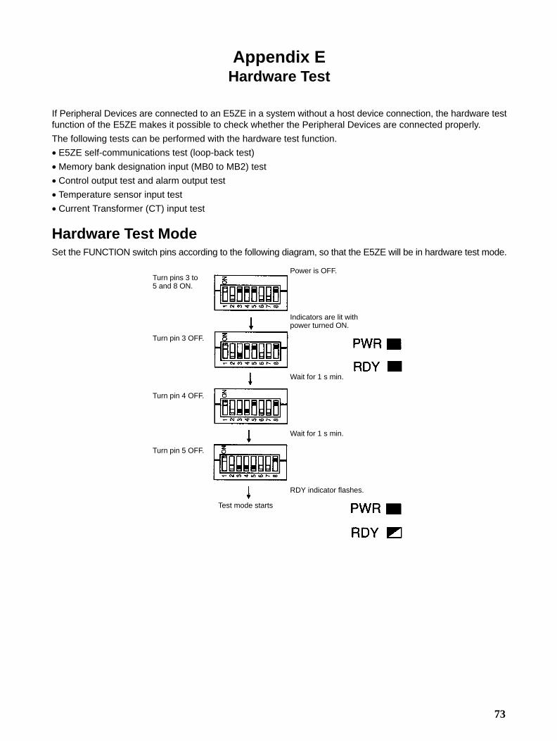
73
Appendix EHardware Test
If Peripheral Devices are connected to an E5ZE in a system without a host device connection, the hardware testfunction of the E5ZE makes it possible to check whether the Peripheral Devices are connected properly.
The following tests can be performed with the hardware test function.
• E5ZE self-communications test (loop-back test)
• Memory bank designation input (MB0 to MB2) test
• Control output test and alarm output test
• Temperature sensor input test
• Current Transformer (CT) input test
Hardware Test ModeSet the FUNCTION switch pins according to the following diagram, so that the E5ZE will be in hardware test mode.
Turn pins 3 to 5 and 8 ON.
Turn pin 3 OFF.
Turn pin 4 OFF.
Turn pin 5 OFF.
Power is OFF.
Indicators are lit withpower turned ON.
Wait for 1 s min.
Wait for 1 s min.
RDY indicator flashes.
Test mode starts

Appendix EHardware Test
74
Test Item SelectionAfter the E5ZE is in hardware test mode, select the tests to be performed using the FUNCTION switch, as shown inthe following table.
Test FUNCTION switch Test check- Commu-
Pin 3 Pin 4 Pin 5 Pin 8ing indica-
tornications
pathCommu-nicationstest
OFF OFF OFF ON None Connected
Memorybank desig-nation input
OFF OFF OFF ON Notconnected
Control out-put andalarm output
ON OFF OFF ON MB0 lit
Temperaturesensor input
OFF ON OFF ON MB1 lit
CT input OFF OFF ON ON MB2 lit
Temperature Sensor Input Test• In this test, if a temperature sensor is correctly connected to a control point, the control output indicator (CH0 to
CH7 or H0 to H7) corresponding to the control point will be lit.• If the control indicator is not lit, recheck the wiring connecting the E5ZE to the temperature sensor. The cause of
the indicator not lighting may be as follows:Thermocouple:A lead of the temperature sensor is disconnected or incorrectly wired.Platinum resistance thermometer:A lead of the temperature sensor is disconnected or incorrectly wired or the A and B terminals of the temperaturesensor are short-circuited.
Procedure1, 2, 3... 1. While in hardware test mode, set pins 4 and 8 of the FUNCTION switch to
OFF.2. Make sure that the MB0 indicator is lit.3. Set the INPUT selector according to the temperature sensor connected to
the control point.4. Make sure that the control output indicators corresponding to each of the
control points are lit.
Memory Bank Designation Input TestIf a contact connecting a memory bank designation input is ON, the MB designation input indicator (MB0 to MB2)corresponding to the contact will be lit. If the MB designation input indicator is not lit, check that the input is wiredcorrectly.
Procedure1, 2, 3... 1. While in hardware test mode, set pin 8 of the FUNCTION switch to ON.
2. Turn ON or OFF the contact corresponding to the memory bank designationinput.
3. Make sure that the MB designation input indicator corresponding to the con-tact that is ON is lit.
Control Output and Alarm Output TestIn this test, a control output or alarm output is turned ON (100% output) and the indicator for the output will light.Depending on the wiring, an output may be unintentionally produced for the wrong control point. Make sure thatany output that is ON will not affect the object being controlled when performing this test.

Appendix EHardware Test
75
Procedure
1, 2, 3... 1. While in hardware test mode, set the UNIT or INPUT selector of the E5ZE sothat the control output or alarm output will be ON. The relationship betweenthe selectors and the outputs is shown in the following tables.
UNIT Selector
Setvalue
Output to beturned ON
0 0
1 1
2 2
3 3
4 4
5 5
6 6
7 7
8 Alarm 1
9 Alarm 2
A HB alarm
B HS alarm
C Temperaturecontroller error
D None
E
F
INPUT Selector
Setvalue
Output to beturned ON
0 0
1 1
2 2
3 3
4 4
5 5
6 6
7 7
8 None
9
A
B
C
D
E
F
Note Outputs will not turn ON if an E5ZE-8 Standard Model is be-ing used.
2. Set pins 3 and 8 of the FUNCTION switch to ON.
Control points
Coolingcontrolpoints(See note.)

Appendix EHardware Test
76
3. Check if the output is ON, the MB0 indicator is lit, and the indicator corre-sponding to the output is lit. (The control output indicator is lit even if theE5ZE is a Current Output Model.)
4. To change the output to be turned ON, set with the UNIT or INPUT selectorafter setting pins 3 and 8 of the FUNCTION switch to OFF.
Current Transformer (CT) Input TestThe CT input test can be performed when a model with heater burnout detection and SSR failure detection is beingused.
The carry current and leakage current of a control point that is measured using CT input are displayed as bargraphs by using the E5ZE indicators.
The carry current is the CT input measurement when the control output is turned ON. The leakage current is the CTinput measurement when the control output is turned OFF.
If the leakage current bar graph is displayed, and the current bar graph indicates a value very different from theheater’s rated value, check the selector, switch settings and the wiring.
Procedure
1, 2, 3... 1. While in hardware test mode, set the control point to be measured and thetype of current with the UNIT selector.
UNIT SelectorSet
valueControl point
to bemeasured
0 0
1 1
2 2
3 3
4 4
5 5
6 6
7 7
8 0
9 1
A 2
B 3
C 4
D 5
E 6
F 7
2. Set pins 5 and 8 of the FUNCTION switch to ON.
3. Check that the MB2 indicator is lit.
The CT input measurement value of the selected control point will be dis-played as a bar graph using the indicators, as follows:
45 A min.40 A min.35 A min.
30 A min.25 A min.20 A min.15 A min.10 A min.5 A min.1 A min.
The second row of indicators willbe lit for the bar graph display.
LitFlashing
Carry currentmeasurement
Leakage currentmeasurement

Appendix EHardware Test
77
4. To change the control point to be measured, set pins 5 and 8 of the FUNC-TION switch to OFF and reset the UNIT selector.
Communications TestThe communications test can be performed when an RS-232C Communications Model or RS-422/RS-485 Com-munications Model is being used.
The E5ZE can transmit and receive data to check its communications circuit by self-diagnosis (loop-back test).
The E5ZE transmits the following character string repeatedly for the communications test. “_” represents a spaceand “[CR]” represents a carriage return.
E5ZE_Copyright_1995_OMRON_Corporation[CR]
Procedure1, 2, 3... 1. While in hardware test mode, set pin 8 of the FUNCTION switch to ON.
2. Short-circuit the send data and receive data at the E5ZE when RS-232C orRS-422 communications are being used, as follows:
Communicationsinterface
RS-232C RS-422
Short-circuit locations Communicationsconnector:
Pins 2 and 3
Communications terminalblock:
Terminals 5 and 2
Terminals 1 and 4
3. Make sure that the SD or RD indicator is lit. The following indicate a commu-nications error:
• The SD and RD indicators are not lit.
• The ERR indicator is lit.
If MB0, MB1, or MB2 is lit, this does not indicate an error.
Current OutputThe E5ZE Current Output Model can be connected to a Power Controller or a Cycle Control Unit to enable moreaccurate temperature control.
Heater voltage Heater voltage
Time Time
Cycle ControlPhase Control
Half cycle 0.2 s (control period)
Phase ControlPhase control is possible when a Current Control Model is used in combination with the G3PX Power Controller.
Phase control will enable highly-precise temperature control and prolongs the life of the heaters connected to theE5ZE.
Cycle ControlCycle control is possible when a Current Control Model is used in combination with the G32A-EA Cycle ControlUnit and a G3PA or G3NH SSR.
Cycle control will enable high-speed response with minimal noise generation.
The relationship between the output values and current output values of the Current Output Model are as follows:

Appendix EHardware Test
78
Control Output
Output value: 0% to 100%
Current output value: 4+0/–0.6 to 20+2/–0 mA
Output with Control Interrupted
Output value: 0%
Current output value: 4+0/–0.6 mA
Output with Control Interrupted by Error
Output with Temperature Controller error
Output value: –16%
Current output value: 1±0.5 mA

79
Appendix FAvailable Models
E5ZE Models
Serial Communications ModelsNo. ofcontrol
Casing Controlmethod
Controloutput
Heaterburnout and
Commu-nications
Input type
points SSR failuredetection
Thermocouple Platinumresistance
thermometer
8 Yes Standard Option Option Option E5ZE-8AAAMTCB-E E5ZE-8AAAMPB-E
Heatingandcooling
Option Option Option E5ZE-8VAAMTCB-E E5ZE-8VAAMPB-E
Model Number Legend:
E5ZE-8AAM-E1 2 3 4 5 6 7
1. Control Point8: 8
2. Control MethodA: Standard
V: Heating and cooling
3. Control OutputA: Option (see note 1)
4. Heater Burnout and SSR Failure Detection (see note 2)A: Option (see note 3)
5. CommunicationsM: Option (see note 4)
6. Input TypeTC: Thermocouple
P: Platinum resistance thermometer
7. Casing
B: Yes
Note: 1. The E53-E8Q Voltage Output Unit or the E53-E8CCurrent Output Unit can be used with the E5ZE. TheE53-E8Q Voltage Output Unit and the E53-E8C Cur-rent Output Unit are sold separately.
2. The heater burnout and SSR failure detection functionof the E5ZE will be invalid if the heating side control out-put of the E5ZE is current output.
3. The E54-E8CT CT Input Unit is required for the heaterburnout and SSR failure detection. The E54-E8CT CTInput Unit is sold separately.
4. The E53-E01 Communications Unit for RS-232C com-munication or the E53-E04 Communications Unit forRS-422 and RS-485 communication can be used withthe E5ZE. The E53-E01 Communications Unit and theE53-E04 Communications Unit are sold separately.
Units Models
RS-232C Communications Unit E53-E01
RS-422/485 Communications Unit E53-E04
CT Input Unit E54-E8CT
Voltage Output Unit E53-E8Q
Current Output Unit E53-E8C
I/O Units (Order Separately)

Appendix FAvailable Models
80
DeviceNet Communications Models
No of controlpoints
Casing Controlmethod
Controloutput
HBA and SSRfailure
detection
Iput type Name
8 Yes Standard Voltage No Thermocouple E5ZE-8AQAD1TCB24VDC
8 Yes Standard Voltage No Platinumresistancethermometer
E5ZE-8AQAD1PB 24VDC
8 Yes Standard Voltage Yes Thermocouple E5ZE-8AQHD1TCB24VDC
8 Yes Standard Voltage Yes Platinumresistancethermometer
E5ZE-8AQHD1PB 24VDC
8 Yes Standard Current No Thermocouple E5ZE-8ACAD1TCB24VDC
8 Yes Standard Current No Platinumresistancethermometer
E5ZE-8ACAD1PB 24VDC
8 Yes Heating andCooling
Voltage No Thermocouple E5ZE-8VQAD1TCB24VDC
8 Yes Heating andCooling
Voltage No Platinumresistancethermometer
E5ZE-8VQAD1PB 24VDC
8 Yes Heating andCooling
Voltage Yes Thermocouple E5ZE-8VQHD1TCB24VDC
8 Yes Heating andCooling
Voltage Yes Platinumresistancethermometer
E5ZE-8VQHD1PB 24VDC
8 Yes Heating andCooling
Current No Thermocouple E5ZE-8VCAD1TCB24VDC
8 Yes Heating andCooling
Current No Platinumresistancethermometer
E5ZE-8VCAD1PB 24VDC
Model Number Legend:
E5ZE-8
1 2 3 4 5 6 7
1. Control Point
8: 8
2. Control Method
A: Standard control
V: Heating and cooling control
3. Control Output
Q: Voltage output
C: Current output
4. Heater Burnout and SSR Failure Detection Function(Not available with Current Output Models.)A: No
H: Yes
5. Communications FunctionD1: CompoBus/D
6. Input TypeTC: Thermocouple
P: Platinum resistance thermometer
7. CasingB: Yes

81
E5ZEMultipoint Temperature Controller
Operation Manual
Revision History
A manual revision code appears as a suffix to the catalog number on the front cover of the manual.
Cat. No. H076-E3-1
Revision code
The following table outlines the changes made to the manual during each revision.
Revision code Date Revised content
H076-E1-1 May 1997 Original production
H076-E1-2 January 1999 Manual completely restructured for clarity and revised to include information on E5ZETemperature Controllers that support DeviceNet communications. (Note that these pagenumbers refer to the previous version.)
H076-E3-1 November 2000 Section 1-4 removed; CompoBus/D changed to DeviceNet throughout; general types ofupdates for these pages: vii, 1, 3, 6, 9, 10, 11, 15, 17, 21, 27, 79.