Embed Size (px)
Citation preview

Esko ProofReference Guide

Copyright
2
© Copyright 2018 Esko Software BVBA, Gent, BelgiumAll rights reserved. This material, information and instructionsfor use contained herein are the property of Esko Software BV-BA. The material, information and instructions are providedon an AS IS basis without warranty of any kind. There are nowarranties granted or extended by this document. Further-more Esko Software BVBA does not warrant, guarantee ormake any representations regarding the use, or the results ofthe use of the software or the information contained herein.Esko Software BVBA shall not be liable for any direct, indirect,consequential or incidental damages arising out of the use orinability to use the software or the information containedherein.The information contained herein is subject to change withoutnotice. Revisions may be issued from time to time to advise ofsuch changes and/or additions.No part of this document may be reproduced, stored in a database or retrieval system, or published, in any form or in anyway, electronically, mechanically, by print, photoprint, micro-film or any other means without prior written permissionfrom Esko Software BVBA.This document supersedes all previous dated versions.PANTONE®, PantoneLIVE and other Pantone trademarks arethe property of Pantone LLC. All other trademarks or regis-tered trademarks are the property of their respective owners.Pantone is a wholly owned subsidiary of X-Rite, Incorporated.© Pantone LLC, 2015. All rights reserved.This software is based in part on the work of the IndependentJPEG Group.Portions of this software are copyright © 1996-2002 The Free-Type Project (www.freetype.org). All rights reserved.Portions of this software are copyright 2006 Feeling Software,copyright 2005-2006 Autodesk Media Entertainment.Portions of this software are copyright ©1998-2003 DanielVeillard. All rights reserved.Portions of this software are copyright ©1999-2006 The BotanProject. All rights reserved.

Copyright C
Part of the software embedded in this product is gSOAP soft-ware. Portions created by gSOAP are Copyright ©2001-2004Robert A. van Engelen, Genivia inc. All rights reserved.Portions of this software are copyright ©1998-2008 TheOpenSSL Project and ©1995-1998 Eric Young ([email protected]). All rights reserved.This product includes software developed by the Apache Soft-ware Foundation (http://www.apache.org/).Adobe, the Adobe logo, Acrobat, the Acrobat logo, Adobe Cre-ative Suite, Illustrator, InDesign, PDF, Photoshop, PostScript,XMP and the Powered by XMP logo are either registered trade-marks or trademarks of Adobe Systems Incorporated in theUnited States and/or other countries. Microsoft and the Microsoft logo are registered trademarks ofMicrosoft Corporation in the United States and other coun-tries.SolidWorks is a registered trademark of SolidWorks Corpora-tion. Portions of this software are owned by Spatial Corp. 19862003. All Rights Reserved. JDF and the JDF logo are trademarks of the CIP4 Organisation.Copyright 2001 The International Cooperation for the Integra-tion of Processes in Prepress, Press and Postpress (CIP4). Allrights reserved. The Esko software contains the RSA Data Security, Inc. MD5Message-Digest Algorithm. Java and all Java-based trademarks and logos are trademarksor registered trademarks of Sun Microsystems in the U.S. andother countries.Part of this software uses technology by Best Color Technolo-gy (EFI). EFI and Bestcolor are registered trademarks of Elec-tronics For Imaging GmbH in the U.S. Patent and TrademarkOffice.Contains PowerNest library Copyrighted and Licensed by Al-ma, 2005 – 2007.Part of this software uses technology by Global Vision. Art-Proof and ScanProof are registered trademarks of Global Vi-sion Inc.All other product names are trademarks or registered trade-marks of their respective owners. Correspondence regarding this publication should be for-warded to:
3

Copyright C
5
Table of Contents
Chapter 1. Copyright ..................................... 2Chapter 2. Table of Contents ....................... 4Chapter 3. Introduction ................................ 6
3.1. What is Esko Proof? .......................................................63.2. Program architecture ....................................................63.3. System requirements ...................................................73.4. Program folders ............................................................73.5. About this manual .........................................................93.6. Conventions ...................................................................9
Chapter 4. Setting up .................................. 104.1. Starting the Esko Proof Client ................................... 104.2. Logging on to an Esko Proof Server ......................... 104.3. System workflows ...................................................... 12
4.3.1. Default system workflows ............................... 124.3.2. Setting up system workflows .......................... 13
Chapter 5. Getting to know your software 245.1. Job Explorer ................................................................. 245.2. System Manager ......................................................... 25
Chapter 6. Settings in System Manager .... 286.1. Menus .......................................................................... 28
6.1.1. File menu ........................................................... 286.1.2. Edit menu .......................................................... 296.1.3. System menu .................................................... 326.1.4. Tools menu ........................................................ 326.1.5. Workspace menu .............................................. 326.1.6. Help menu ......................................................... 32
6.2. Toolbar ........................................................................ 336.3. Property Inspector ..................................................... 33
6.3.1. User settings ..................................................... 346.3.2. Workflow settings ............................................. 346.3.3. Output device settings ..................................... 59
Chapter 7. Managing system workflows .. 647.1. Making changes to system workflows ..................... 64
7.1.1. Available menu commands ............................. 647.2. Saving and restoring settings ................................... 67
Chapter 8. Settings in Job Explorer ........... 748.1. Menus .......................................................................... 74
8.1.1. File Menu ........................................................... 748.1.2. Edit menu .......................................................... 758.1.3. Nesting menu .................................................... 818.1.4. Tools menu ........................................................ 818.1.5. View menu ......................................................... 828.1.6. Workspace menu .............................................. 858.1.7. Help menu ......................................................... 85
8.2. Context menus ........................................................... 858.3. Toolbars ....................................................................... 86
6
8.3.1. First toolbar .......................................................868.3.2. Second toolbar .................................................. 87
8.4. Property Inspector ...................................................... 898.4.1. File tab > Source File Information pane ......... 898.4.2. File tab > Warning and Error pane .................. 898.4.3. File tab > Subfiles pane .................................... 908.4.4. File tab > Job Merge pane ................................ 908.4.5. File tab > PS/EPS/PDF pane .............................. 908.4.6. Layout tab > Virtual Sheet Size pane .............. 908.4.7. Layout tab > Layout Options pane .................908.4.8. Layout tab > Nesting pane ...............................908.4.9. Layout tab > Step & Repeat pane ................... 908.4.10. Layout tab > Job Ticket pane ......................... 918.4.11. Finishing tab > Crop Marks pane .................. 918.4.12. Output tab > Print Settings pane .................. 918.4.13. Output tab > Media Settings pane ................ 918.4.14. Output tab > Media Configuration pane ..... 918.4.15. Output tab > Advanced Print Options pane 918.4.16. Output tab > Special Printer Settings pane . 928.4.17. System tab > Device pane .............................. 92
8.5. Keyboard shortcuts .................................................... 928.5.1. Activating options ............................................. 928.5.2. Activating toolbars ............................................928.5.3. General ............................................................... 938.5.4. Page position .....................................................948.5.5. Nesting jobs....................................................... 948.5.6. Zoom .................................................................. 958.5.7. Rulers, guides and grid ..................................... 95
Chapter 9. Printing and monitoring print jobs 98
9.1. Printing directly from Esko Proof .............................. 989.2. Printing via a hotfolder ............................................100
Chapter 10. Nestings .................................10410.1. What are nestings? .................................................10410.2. User interface ..........................................................10510.3. Creating nestings ....................................................106
10.3.1. Automatic nestings .......................................10610.3.2. Manual nestings ............................................106
10.4. Editing nestings .......................................................10710.4.1. Adding jobs to a nesting ..............................10710.4.2. Adding/deleting sheets ................................10810.4.3. Removing jobs from nestings ......................108
Chapter 11. Esko Proof Control ................11011.1. What is Esko Proof Control? ..................................11011.2. Available features ...................................................110
11.2.1. Esko Proof Server Stop/Esko Proof Server Start/Esko Proof Server Restart ......................................................110
11.2.2. Esko Proof Client Start .................................11111.2.3. Esko Proof Server Configuration (Windows only)
111

Table of Contents T
11.2.4. Autostart Esko Proof Control (Windows)/Open at Login (Macintosh) .............................................................. 111
11.2.5. Server File Maintenance .............................. 11111.2.6. Exit (Windows)/Quit (Macintosh) ................ 111
Chapter 12. Troubleshooting ................... 11212.1. Server/Logging on .................................................. 11212.2. Printing .................................................................... 11412.3. Media profiles ......................................................... 11712.4. USB devices ............................................................. 11812.5. Support .................................................................... 119
Chapter 13. Uninstalling ........................... 120Chapter 14. Glossary ................................. 122Chapter 15. Index ...................................... 128
7

Chapter 1: Introduction
8
This is a brief introduction to Esko Proof. It describes the pur-pose for which the software was designed, provides details ofthe hardware and software requirements necessary to set upand run your software and gives an overview of the folderstructure.
1.1 What is Esko Proof?
Esko Proof is the perfect tool for anyone wanting to achievehigh-quality color reproduction. The software is easy to useand produces color-accurate output, while avoiding the needfor complicated color management settings.The standard media and simulation profiles provided with thesoftware enable your printer to simulate the colors achievedon a professional printing press, thereby making it possible toreproduce genuine proofs on a conventional printer.In addition, the software includes many settings that are es-sential in the production industry for modifying photographicimages.Esko Proof is, therefore, ideal for printing houses, designers,photographers, agencies and service providers in the printmedia industry, for whom predicting color-accurate print re-sults constitutes an important part of their daily work.
1.2 Program architecture
Esko Proof is based on a Server/Client architecture of modulardesign. A Server version installed on one computer can be ac-cessed from an unlimited number of Client versions installedon the same or on any other computer. This allows users max-imum flexibility in customizing the software to suit their ownparticular workflow requirements.The Server runs on Windows and the Client runs on both Win-dows and Macintosh.The minimum version of the software comprises:

Introduction 1
• Esko Proof (includes one Server version and an unlimited number of Client and Job Monitor versions)
- The Server is the “brain” behind the software. It runs as a service and is responsible for job processing. When you restart your computer after installing the software, the Server software starts automatically.
- The Client software simply provides an intuitive user interface. All settings and actions initiated on the Client computer are sent to the Server for processing.
• A license to connect to one standard output deviceHowever, a Verification add-on module is available to supple-ment the standard version.
1.3 System requirements
You can find the system requirements necessary to install andrun Esko Proof successfully on the Esko website: see SystemRequirements for Esko Proof Server.
1.4 Program folders
This section gives an overview of the file structure of EskoProof to enable you to locate program files, custom files andother important files quickly and easily.
9

10
• Installation folder
When installing Esko Proof at the default location, its fixed program components are installed in the \Program Files (x86)\Esko\Esko Proof folder.
If you chose not to install Esko Proof at the default location, all the program folders are installed in your chosen folder.
The Esko Proof folder contains the following subfolders:
Folder name Subfolder name Contains
Client Program files for Esko Proof, including addi-tionally licensed options
IT8_CharacterizationData
IT8.7/4 profiling charts for Fogra Proof Certifica-tion
MonitorProfile Default and custom monitor profiles
Samples • Lineal_01.ps for calculating media length correction
• Print & Cut test files
• Test files for white ink printing
• Work folder
You will find all work files directly associated with job processing located in the \ProgramData\Esko\Esko Proof folder.
If you cannot see the ProgramData folder, it may be because it is set up as a hidden folder on your computer. Open Control Panel, and search for “Show hidden files and folders”. On the View tab, make sure that the advanced setting “Show hidden files, folders, and drives” is selected.
• Media profiles
Media profiles are installed in the following folders:
Windows \ProgramData\Esko\Esko Profiles
Macintosh /Library/Application Support/Esko/Esko Profiles

Introduction 1
1.5 About this manual
Users of this manual should already be familiar with:
• The operating system on which their software is installed
• The subject of color management
1.6 Conventions
Cautions must be read carefully. They indicate permanent ac-tions which, once executed, cannot be undone.Tips and information which you may find useful.The screen captures illustrated in this manual have been cre-ated from a mixture of both the Windows and Macintosh ver-sions of the software. Depending on which version you areusing, the image on your screen may look slightly different.However, unless otherwise stated, the functionality is thesame for both operating systems.
11
Chapter 2: Setting up
2.1 Starting the Esko Proof Client
10
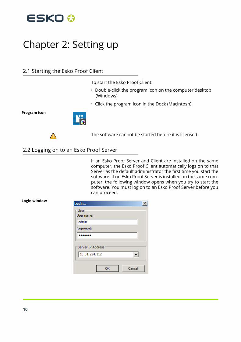
To start the Esko Proof Client:
• Double-click the program icon on the computer desktop (Windows)
• Click the program icon in the Dock (Macintosh)
Program icon
The software cannot be started before it is licensed.
2.2 Logging on to an Esko Proof Server
If an Esko Proof Server and Client are installed on the samecomputer, the Esko Proof Client automatically logs on to thatServer as the default administrator the first time you start thesoftware. If no Esko Proof Server is installed on the same com-puter, the following window opens when you try to start thesoftware. You must log on to an Esko Proof Server before youcan proceed.
Login window

Setting up 2
If a firewall is in use in your network, make sure that it is con-figured to enable communication between Server and Client.The following ports must be available on the Server and Clientcomputers:
Port Used for
50005 to 50026 General communication between the Esko Proof Server and the Esko Proof Client
4108 Epson Spectroproofer
8051, 8052, 8053, 8054, 8061, 8062, 8063, 8064
Internal communication of the Esko Proof Server
Furthermore, make sure that the following applications cancommunicate with the network:
Server Esko_Proof_Server.exeEsko_Proof_Control.exe
Client Esko_Proof_Client.exeEsko_LinTool.exeEsko_Verification.exe
For the Windows firewall, the port and application settings arecreated automatically by the installer.
TO LOG ON TO AN ESKO PROOF SERVER
1 Type the default login information, as follows:
User name: adminPassword: admin
This is the default administrator login information. You can log in as a different user if Esko Proof has already been set up and additional users have been created.
11

12
2 Select the IP address of the Server computer.
A list of all available Esko Proof Servers in your sub-network is displayed with IP address in the drop-down list. If Server and Client are installed on the same computer, the IP address of the local Server is placed first in the list. However, you can also type in manually the IP address of an Esko Proof Server. Ask your system administrator if you are not sure which TCP/IP address to use.
If you are currently logged on to a Server on a different computer and want to log on to a local Server installed on the same computer as the Esko Proof Client, you can type “localhost” instead of an IP address. This means that the default IP address 127.0.0.1 is used by the software.
3 Click OK.
The connected Server is displayed at the bottom of the program window.
2.3 System workflows
This documentation makes a distinction between the terms“system workflow” and “workflow”. The term “system work-flow” consists of a user, workflow and output device. It refersto all work processes from file input by a certain user to fileoutput on a specified printer. The term “workflow” is con-cerned only with file processing and the way files are handledin Esko Proof.
2.3.1 Default system workflows
Esko Proof is installed with one default system workflow, con-sisting of two users, one workflow and one output device.
Default system workflow configuration
The user “admin” (default password “admin”) is permitted tocreate, set up and manage system workflows in System Man-ager.

Setting up 2
The user “guest” (default password “guest”) is permitted toprint and manage his or her own print jobs in Job Explorer butdoes not have access to System Manager and cannot create ormodify system workflows. “Guest” enables infrequent users ofEsko Proof to log on quickly and easily, without first having tobe defined as an individual user. The workflow “Esko Linearization” and the output device “Lin-earization device” are used primarily in conjunction with EskoLinTool for printer linearization. Only users with administratorrights can print jobs via this workflow. You must configure the linearization device before you can ac-cess Esko LinTool.If you set up a workflow and output device as part of the instal-lation procedure, these will also be visible in System Manager.
2.3.2 Setting up system workflows
You can set up a system workflow in:
• Setup Wizard (Windows) or Setup Assistant (Macintosh)
The Setup Wizard/Assistant leads you logically through the minimum of steps necessary to set up a system workflow for the default users. You can fine tune your workflow settings later in System Manager, if required.
Normally, you will already have created a system workflow in this way when you installed Esko Proof.
• System Manager
In System Manager, you can create additional users, workflows and output devices. You can also change the configuration of existing workflows.
To set up an output device, you must have media profiles for your printer installed on the computer. If you did not install any media profiles during program installation, install them now from the software DVD.
• Setting up in Setup Wizard/AssistantSetup Wizard/Assistant provides step-by-step instructions onhow to configure a basic system workflow.
TO SET UP A SYSTEM WORKFLOW IN SETUP WIZARD/ASSISTANT
You can click Finish Now at any time to exit the setup proce-dure. Any settings that you have already made are saved.1 In the toolbar, click System Manager.
13

14
2 From the System menu, choose Setup Wizard (Windows) or Setup Assistant (Macintosh).
Introduction window
3 Click Continue to open the Workflow dialog.
Creating a workflow
4 Leave “Custom” selected in “Workflow”, and “Esko Proofing workflow” selected in “Template”.

Setting up 2
5 Click Continue to display the Output device dialog.
Selecting an output device
6 From the drop-down list, select “Create a new output device”.7 Select the Manufacturer and Device type of your output device.
When you make a selection, the Setup Wizard/Assistant displays the number of media profiles installed for the output device.
If no media profiles are installed, an error message is displayed. In this case, you must cancel the setup and install the appropriate media profiles from the software DVD.
15

16
8 Click Continue to open the Device connection dialog.
Setting up a connection

Setting up 2
9 Select a connection type.
• Select “Print to system printer” to print to a Windows printer that has already been set up as a system printer in Windows.
The available printers are listed in the drop-down list.
This setting is only available for Windows and the system printer must be a printer supported by Esko Proof.
• Select “Print via IP network” if you want to print via TCP/IP.
Type the IP address in the appropriate edit box. You can check whether the connection to the printer has been properly established by clicking Test. To test the connection, the printer must be switched on. If you receive an error message, consult your system administrator for advice.
Select the type of TCP/IP protocol that your printer uses for data transfer.
- Raw on port
Most printers support RAW printing to port 9100. However, please note that this setting depends on the network settings made at the printer and may, therefore, be different.
- LPR queue
If your printer supports LPR printing, type the queue name in the edit box.
In most cases, you can leave this edit box blank. It is normally only necessary to type a queue name if you are printing via a Unix system or a print server with multiple interfaces. Refer to your printer manual for further information.
• Select “Print via port” to print to a printer connected via USB to the Server computer.
The printer must be switched on when you start Esko Proof. Otherwise, it will not be automatically detected.
17

18
10 Click Continue to open the Media type dialog.
Selecting a media type
11 Select the type of ink inserted in the printer.12 Select the media you want to use.
Esko Proof provides media profiles that have been created for specific combinations of media, ink and resolution. Furthermore, you can implement your own custom media profiles that have been created for your exact printer.
13 Select a calibration set.
The calibration set defines a set of print conditions, and ensures that the printer’s behavior is adjusted optimally to the media.

Setting up 2
14 Click Continue to open the Media size dialog.
Selecting a media size
15 In the Media Size dialog, make media-specific settings.
Which settings are available depends on the selected printer.
• From the “Source” drop-down list, select the source of media feed.
• From the “Format” drop-down list, select the media size. Only default sizes are available initially, but you can define your own media sizes in Esko Proof.
• If supported by your particular printer, you can select borderless printing.
16 Click Finish.Your workflow and output device are now set up.
• Setting up in System ManagerCreating system workflows in System Manager gives you ac-cess to all the settings available in Esko Proof.Once you have created a system workflow, you need to set itonline.
TO CREATE A NEW USER
You can set up each co-worker as a user in Esko Proof and de-fine user privileges for each.
19

20
1 Create a new user by either:
• Clicking New User in the toolbar
• Right-clicking on an existing user in the layout area and choosing New User from the context menu
• Choosing File > New > User
A user with the name “New User 1” is created. The User tab displays the Profile pane.
2 Define a name for the user by either:
• Double-clicking on “New User 1” in the layout area, overwriting the default name and pressing <Enter>
• Overwriting “New User 1” on the Profile pane
3 On the Profile pane, define a password. Then confirm it by re-typing it in the appropriate edit box.4 Using the drop-down list, specify whether the new user will have administrator or user rights.
Administrators have access to System Manager and are permitted to create, set up and manage workflows. Users without administrative rights are only able to submit print jobs and make job-specific settings in Job Explorer.
5 In the toolbar, click Save.

Setting up 2
TO CREATE A WORKFLOW
1 Create a new workflow by either:
• Clicking New Workflow in the toolbar
• Right-clicking on an existing workflow in the layout area and choosing New Workflow from the context menu
• Choosing File > New > Workflow
The window New Workflow from Template opens.
New Workflow from Template dialog
2 Highlight a template in the list.
Initially only the default workflows are available as templates. However, once you have created your own workflows, you can save them and add them to the list. Workflow templates are saved with all the settings defined for the original workflow and serve as the basis for new workflows with similar properties. This enables you, for example, to use the same workflow settings to print to different output devices, since each workflow can only be connected to one printer at a time.
3 Click Load.
A new workflow with the name of the selected workflow template is created, supplemented by a consecutive number.
21

22
4 Define a unique name for the workflow by either:
• Double-clicking on the new workflow in the layout area, overwriting the default name and pressing <Enter>
• Overwriting the default name on the General pane of the Workflow tab
5 Type a brief workflow description, if required.
The default settings are automatically displayed, but you can add any additional information.
6 Define your preview and file deletion settings, if required.7 Check the settings which affect the processing and print speed of your jobs.8 On the remaining tabs, make any additional settings.
For example, on the Layout tab, you can set up your workflow for automatic nesting or step & repeat.
9 When you are finished, save your workflow by clicking Save in the toolbar.To save your newly created workflow as a basis for furtherworkflows, choose Save as Template from the File menu anddefine a name.
The next time you create a new workflow, it will be displayed in the window “New Workflow from Template”.
TO CREATE A NEW OUTPUT DEVICE
1 Create a new output device by:
• Clicking New Output Device in the toolbar
• Right-clicking on an existing output device in the layout area and choosing New Output Device from the context menu, or
• Choosing File > New > Output Device
2 Set up the new output device.
See also:
“User settings” on page 35
“Workflow settings” on page 35
“Output device settings” on page 63
Setting up 2
• Setting system workflows onlineWhen you have created a system workflow, the next step is toset it online.When a workflow is fully online, all jobs are automatically pro-cessed and printed as soon as they are loaded in Esko Proof.
TO SET A SYSTEM WORKFLOW ONLINE
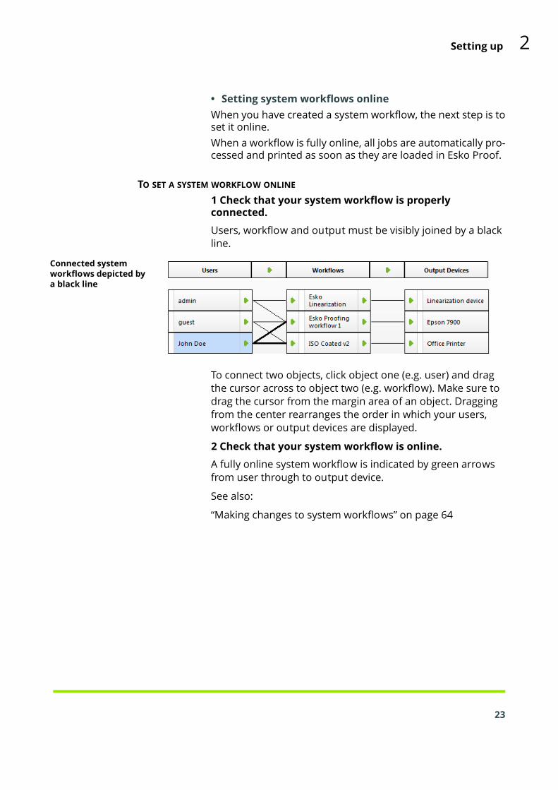
1 Check that your system workflow is properly connected.
Users, workflow and output must be visibly joined by a black line.
Connected system workflows depicted by a black line
To connect two objects, click object one (e.g. user) and drag the cursor across to object two (e.g. workflow). Make sure to drag the cursor from the margin area of an object. Dragging from the center rearranges the order in which your users, workflows or output devices are displayed.
2 Check that your system workflow is online.
A fully online system workflow is indicated by green arrows from user through to output device.
See also:
“Making changes to system workflows” on page 64
23

Chapter 3: Getting to know your software
24
The user interface of Esko Proof is divided into the followingtwo program windows, which you display by clicking the ap-propriate tab in the program window bar:
• Job Explorer (administrators and users)Here you load and apply settings to your print jobs.
• System Manager (administrators only)Here you set up and configure your workflows and printers, create users and grant them access rights to print via specific workflows.
3.1 Job Explorer
Job Explorer is where you load, organize and preview jobs, andmake job settings.
Job Explorer1 Menu bar2 Toolbars3 Job list4 Property inspector5 Preview window6 Selector
56
4
1
2
3

Getting to know your software 3
The job list provides an overview of loaded jobs. A selected jobis previewed in the preview window and you can configurejob-specific settings in the property inspector.The Selector acts as filter, listing jobs according to workflow,output device or job status. The button “All Jobs” lets you viewall your jobs in the job list.The job list contains job-specific information, such as job sta-tus and job name. Each job status is indicated by a differentcolor.You can add or remove columns to display the informationthat is most important to you by right-clicking on a columnheading and choosing the required items from the contextmenu.You can also change the order of the columns in the job list byholding down the mouse button on a column heading anddragging to the left to a different position. The column head-ing “Job Status” and “Name” are fixed and cannot be reposi-tioned or removed.
25

3.2 System Manager
26
System Manager is where you create and configure systemworkflows. It is available only to users with administrator sta-tus.
System Manager1 Layout area for
creating, configuring and managing system workflows
2 Property inspector
1
2
System Manager gives you a clear overview of:
• which users can print to which workflows
• the output device assigned to each workflowIn System Manager, you can halt jobs at certain stages of theworkflow. This may be desirable to perform certain tasks. Forexample, a workflow can be diverted quickly and easily to an-other output device if a particular printer needs servicing.The changes you make in this window are applied to all jobs inthe job list that have not yet been processed.
See also:
“Setting system workflows online” on page 23

Getting to know your software 3
27
Chapter 4: Settings in System Manager
28
These sections describe the individual settings concerned withcreating and setting up system workflows. They deal only withthose settings available in the basic software configuration.Settings related to add-on modules are dealt with in the re-spective sections.
4.1 Menus
4.1.1 File menu
• New- User
Choose this command to add a new user.
- Workflow
Choose this command to create a new workflow that is based on one of the default workflow templates or on any other workflow that you have previously saved as a workflow template.
- Output Device
Choose this command to create a new output device.
• Import Environment
Choose this command to load a backup file of your system workflow environment.
• Save
Choose this command to save all the changes made to the system workflow.
• Save as Template
Choose this command to save a new workflow template you have created under any chosen name. Workflow templates form the basis for new workflows with the same or similar settings.
Settings in System Manager 4
• Save as Environment
An environment is a combination of workflow and printer. Choose this command to create a backup copy of your workflow and printer settings.
• Backup
Choose this command to create a backup copy of your system workflows.
• Restore
Choose this command to restore a previously backed up copy of your system workflows.
• Login
Choose this command to display the “Login” dialog. This command enables you to log in under a different user name or to log on to a different Server.
• Logoff and Exit
Choose this command to log off and exit the Esko Proof Client. The next time you start Esko Proof the “Login” dialog opens.
It is advisable to log off with this command if more than one person is using the same computer. This ensures that each user logs on to his own workflow settings.
• Exit
Choose this command to exit Esko Proof. The next time you start Esko Proof you will automatically be logged on with the same user data.
In the Macintosh version of the software, you will find the command in the Esko Proof menu.
29

4.1.2 Edit menu
30
• Languages (Windows only)
Choose this command to change the language in which the user interface is displayed. You must restart the Esko Proof Client before the new language takes effect. By default, the language of the operating system is displayed.
On a Macintosh, you can change the language the international settings in “System Preferences”.
If you change the display language, make sure that the help set for that language is installed. Otherwise, no help will be available from the Help menu. You can install help sets in additional languages from the software DVD.
Please note that to display one of the supported Asian languages on a PC, Esko Proof must be running on an operating system that supports 2-byte fonts.
• Measurement system
Choose this command to define which system of measurement is used in Esko Proof. The default setting corresponds with the system of measurement set up in the operating system. However, you can choose between millimeter, centimeter, meter, inch and foot.
• Monitor Profile
Esko Proof provides you with the opportunity to verify color accuracy on a computer screen. This is known as “soft proofing”. However, much like the color output of each printer can vary greatly, so each monitor displays color slightly differently. To overcome this problem, it is important that the monitor is regularly calibrated to a certain standard. Monitor calibration consists of two steps:
- adjusting the brightness and control settings on the monitor itself to set values and
- creating a monitor profile, which defines the white point, gamma and RGB phosphor settings
Windows and Macintosh computers provide standard monitor profiles as part of the operating system software. In Esko Proof you can select a monitor profile that you have created yourself or one provided with the operating system.

Settings in System Manager 4
• Copy
Choose this command to copy a selected user, workflow or output device to the clipboard.
• Paste
Choose this command to insert a duplicate of a user, workflow or output device from the clipboard.
• Delete
Choose this command to delete the selected user, workflow or output device.
• System
This command enables you to make global settings to connect and disconnect users, workflows and output devices to and from a system workflow.
31

32
• User
This command contains user-related settings which enable you to:
- Check which workflows a selected user is connected to
- Check if the selected user is online/offline
- Connect the selected user to all workflows
Users with no administrator rights cannot be connected to the Esko Linearization workflow.
- Disconnect a selected user from all workflows
- Create a new user
- Delete the selected user
• Workflow
This command enables you to:
- View which users are connected to the selected workflow
- View which output device is connected to the selected workflow
- Set up a connection from user to workflow so that user can load jobs in Esko Proof
- Set up a connection to an output device so that jobs can be processed and printed
- Connect all users to the selected workflow
- Disconnect all users from the selected workflow
- Disconnect the output device from the workflow
- Save a system workflow as an environment
- Create a new workflow
- Delete a selected workflow
• Output Device
This command enables you to:
- View which workflows are connected to the selected output device
- Check if a selected output device is online/offline
- Connect all workflows to the selected output device

Settings in System Manager 4
- Disconnect the selected output device from all workflows
- Create a new output device
- Delete a selected output device
- Assign a color to the output device
4.1.3 System menu
• Setup Wizard (Windows)/Setup Assistant (Macintosh)Leads you step by step through the settings necessary to create new system workflows or to make changes to existing ones.
• Clean Up
Choose this command to delete files that are no longer needed. You can choose to delete output files, preview files, temporary files, files loaded in the job list and log files. Alternatively, select “All” to delete all.
4.1.4 Tools menu
• Esko VerificationIf you have a valid license for Esko Verification, you can choose this command to start it.
• Job Explorer
Choose this command to switch to Job Explorer.
• System Information
Choose this command to display information about the resources used and the jobs processed by the Esko Proof Server.
4.1.5 Workspace menu
• Property TabsThis displays the tabs available in the right pane. To hide a tab, click an item that has a check mark next to it.
To show a hidden tab, click an item that does not have a check mark next to it. To show all hidden tabs, click All.
33

4.1.6 Help menu
34
• Help
Choose this command to start the HTML online Help for Esko Proof.
If you change the display language, make sure that the help set for that language is installed. Otherwise, no help will be available from the Help menu. You can install help sets in additional languages from the software DVD.
• About
Choose this command to open a window with details of your program version.
In the Macintosh version of the software, you will find the command in the Esko Proof menu.
4.2 Toolbar
New User:Click this button to add a new user.New Workflow:Click this button to add a new workflow to the system work-flow. New workflows are based on previously saved workflowtemplates.New Output Device:Click this button to add a new printer.Save:Click this button to save your settings.Delete Selected Object:Click this button to delete a selected item.Esko Verification:Click this button to start Esko Verification (if you have a licensefor it) — a tool for verifying the colors on your proof.
4.3 Property Inspector
The Property Inspector displays the settings of the selected:
• user
• workflow
• output device

Settings in System Manager 4
All the settings you make in System Manager are made for aselected workflow and are applied to all jobs processed viathat workflow. Job-specific settings are possible in Job Explor-er, which override the settings made in System Manager.The Info pane on the Server tab is accessible from all areas ofSystem Manager. It displays information about current systemutilization and the job status of all jobs. It also displays theamount of used hard disk space on your computer.Esko Proof requires a certain amount of free disk space. Beaware that if less than 2.5% free disk space is available, youmay not be able to load and process jobs in Esko Proof.
4.3.1 User settings
The users settings are available when you select a user in thelayout area.• Profile tab > User Account pane
• User name
Use this edit box to type a name for a new user or change the name of an already defined user.
• Password
Define a password. Note that passwords are case-sensitive.
Confirm the password by retyping it in the appropriate edit box and clicking Apply.
You may change the password of the default administrator if you wish. However, please note that if the default administrator is the only user with administrator rights and the password is misplaced, you will no longer be able to access the software to make settings at administrator level.
• User role
Select whether the user will have administrator or user rights.
Users with administrative rights have access to System Manager and are permitted to create, set up and manage workflows.
Users with no administrative rights are only able to submit print jobs and make job-specific settings in Job Explorer.
4.3.2 Workflow settings
The workflow settings are available when you select a work-flow in the layout area.35

36
• Workflow tab > Basic Information pane
• Name
Type a name for a new workflow or change the name of an already defined workflow. It is not possible to change the name of the default linearization workflow.
• Description
The Description box gives details of some of the more important settings of the template used to create the workflow. You can edit the text to reflect changed settings or add comments.
• Delete source files
Use the drop-down list to choose when job files saved to the JobFolder are automatically deleted. Files can be deleted:
- Never
- Automatically after printing
- After a specified number of days. Type the time span in days in the edit box.
Any setting you make for source file deletion is automatically applied to output/preview files. It is not possible to delete source files alone.
• Delete source files from hotfolder
Select this check box to delete job files copied to a hotfolder.

Settings in System Manager 4
• Delete output/preview files
During job processing, Esko Proof creates a print file of each job and saves it to the Output folder. If the preview function is activated for the workflow, a preview file is also saved to the Preview folder. Use the drop-down list to choose when output and preview files saved to these folders are automatically deleted. Files can be deleted:
- Never
- Automatically after printing
- After a specified number of days. Type the time span in days in the edit box.
If you have previously made a setting to delete source files, the same setting is automatically applied to output/preview files. An independent setting is only possible if you have specified that source files are never to be deleted.
• Workflow tab > Preview pane
• Resolution
Select a radio button to define the resolution of a displayed preview in dpi or pixel.
• Workflow tab > Speed pane
• High priority workflow
Select this check box to ensure that all jobs printed via this workflow go straight to the front of the print queue, i.e. if more than one workflow is printing to the same printer, all jobs received via a high-priority workflow will be output first.
• Print bi-directional
If your printer supports this feature, select the check box to increase print speed. Bi-directional printing is faster than unidirectional printing, as the print head prints in both directions, but may provide less accurate results.
Please note that some settings in the linearization may be overwritten.
37
38
• RIP and print on the fly
Select this check box if you want your jobs to start printing as soon as processing starts. If this check box is not selected, printing will not commence until job processing has been fully completed.
Simultaneous processing and printing may cause the printer to pause from time to time. This can lead to undesirable lines on the printout.
• RIP Resolution
Use the slidebar to define whether speed or quality is the more important factor during processing. By reducing the resolution at which the print job is processed you increase the speed of output.
Processing a print job at a low resolution may result in a draft-quality output, whereas printing at a high resolution setting will take longer. It is not possible to process a print job at a higher resolution than the output resolution.
• File tab > Job detection paneTo enable job detection settings, you must first set the work-flow offline. To do so, click on the green arrow at workflow en-try. It becomes a red square to show that the workflow isoffline.

Settings in System Manager 4
• Hotfolder
Define the folder that is routinely monitored by Esko Proof for incoming files. When new files are detected, they are automatically loaded for processing.
A hotfolder in usually located in a network environment where it can be accessed by any number of users who do not have the Esko Proof Client installed on their computers.
The Esko Proof Server runs on Windows as a service. To enable communication with hotfolders via the network, you need to assign network access rights for the Esko Proof Server by creating a user with administrative rights. See “Printing via a hotfolder” on page 101.
If Server and Client are installed on the same computer, click Choose to navigate to the folder you wish to use as a hotfolder. A hotfolder can be located anywhere within an Esko Proof Server installation folder or anywhere on the network.
Please be aware of the consequences of inadvertently defining your computer desktop or a network drive as a hotfolder. This will cause all the files saved to this location to be loaded.
If Server and Client are installed on different computers, you can only print to hotfolders located inside the JobFolder of the Esko Proof Server application folder.
It is recommended that you use a computer on which an Esko Proof Server is installed to set up hotfolders.
39

40
• Enable load balancing
If the selected hotfolder is being monitored by more than one workflow, you have to select this check box to instruct Esko Proof to distribute the workload by diverting print jobs to the first idle workflow that becomes available.
This ensures that print jobs are always output as quickly as possible, e.g. if one workflow is busy processing a large-volume print job or if one Server encounters a problem. Once a job starts being processed, it is locked to other workflows. This prevents jobs being processed by two workflows simultaneously.
The advantage of load balancing is that it utilizes all the available system resources as efficiently as possible.
The following diagrams illustrate two possible scenarios for using load balancing.
Example of load balancing using different Servers
Hotfolder
Server
Server
Server

Settings in System Manager 4
Example of load balancing using different workflows Workflow_1
Workflow_2
Workflow_3
Hotfolder
Please note that workflows printing via the same hotfolder may not necessarily be configured identically. This can result in unsatisfactory color results if the workflow settings are different or if a different printer is connected.
• Create virtual printer
This setting sets up a virtual printer for the workflow. It can be selected from the print dialog of any application and thus enables users to print directly to Esko Proof.
To set up a virtual printer, you must first define a hotfolder on this pane. Then, select the check box and define a name for the virtual printer. This is the name that will be displayed in the printer list of the application.
The virtual printer is created when you switch the workflow online at workflow entry.
41

42
• Remote job import
A remote container saves a CMYK job and its settings in a single file. A remote container is used primarily to verify the color accuracy of a job that is printed at multiple sites.
When you process a remote container in Esko Proof, you can apply the job’s color management settings or the workflow’s color management settings.
- Use settings of remote job
This setting ensures that the original color management settings, including the simulation (reference) profile, are automatically selected when you load the job.
In this case, the color management settings defined for the workflow will be ignored.
- Use settings of workflow
This setting ensures that the color management settings of the workflow are automatically selected when you load the job.
In this case, the color management settings of the original job will be ignored.
See also:
“Making changes to system workflows” on page 64
“Printing and monitoring print jobs” on page 98
“Printing via a hotfolder” on page 101
“Esko Proof Server Configuration (Windows only)” on page 111
• File tab > PS/EPS/PDF pane
• Stop job processing if font is missing
When you select this check box, job processing is halted if Esko Proof detects a missing font. The missing fonts are listed. However, you can still preview jobs correctly.
If the check box is left unchecked, print jobs with non-available fonts are output using the default font Courier instead.

Settings in System Manager 4
• Divide multi-page PDF files into single-page jobs
By default, a multi-page PDF job is loaded as a single job. It means that job settings are applied to all pages. To make individual page settings, load each page as a separate job.
43

44
• Size definition:
You can specify which PDF setting is applied to calculate the page size.
- “Media box” describes the size of the output media and is displayed in the print dialog. All the other boxes are smaller and are found inside the media box.
- “Crop box” defines the region to which the contents of the page are to be clipped (or cropped) when displayed or printed. Unlike the other boxes, the crop box has no defined meaning in terms of physical page geometry or intended use. It merely suggests where the page should be clipped.
- “Bleed box” defines the bounds to which the contents of the page should be clipped when output in a production environment.
- “ArtBox” defines the meaningful content of the page, including potential white space.
- “Trim box” defines the intended dimensions of the finished page after trimming. This type of box is used by imposition applications for arranging the order of pages.
PDF boxes1 Media box2 Bleed box3 Trim box4 ArtBox 1
2
3
4
- “Calculate page size”: select this check box to instruct Esko Proof to calculate the page size. This is done by RIPping the whole document at a low resolution. It is slower than extracting the information from the bounding box but produces more accurate results.

Settings in System Manager 4
• In-RIP separation
In-RIP separations are spot colors that have been defined in an external DTP or in a graphics program and saved as a single job file. You can output in-RIP information as follows:
- Enable
PDF jobs with in-RIP separations are printed as separated files (C, M, Y, K, plus spot colors). Jobs with no in-RIP information are simply printed composite (CMYK).
- Disable
In-RIP information is ignored. PDF jobs are printed composite (CMYK). Note that pre-separated files are always printed separated, even though they do not contain in-RIP information.
- Force
In-RIP information is applied to PostScript level 3 and PostScript level 2 jobs, as well as to PDFs that were created with older versions of Acrobat.
PostScript files with in-RIP separations normally require a special PostScript command to ensure that the in-RIP information is interpreted correctly. However, not all PostScript printers support in-RIP separations — PostScript level 3 does, PostScript level 2 does not.
By forcing in-RIP separation, you make sure that the in-RIP information from the graphics program is processed, even if the special PostScript command is missing, and regardless of the type of PostScript printer that was used to create the file.
If you do not force the use of in-RIP separation, jobs are output as follows:
• PostScript jobs that were created for a PostScript level 3 printer are output separated on printers that support in-RIP separation. If the printer does not support in-RIP separation, the job is output composite.
• PostScript jobs that were created for a PostScript level 2 printer are always output composite, because spot color separations cannot be correctly interpreted.
45

46
• Simulate overprinting in composite jobs
This check box enables you to determine whether overprint settings defined in your image file are applied during printing.
Normally, when two objects of different colors overlap, there is a knock-out effect, i.e. they will not print on top of each other. Intentionally printing one layer of ink on top of another is known as overprinting. Overprinting is sometimes used to prevent gaps between adjoining colors.
This setting lets you simulate overprinting in composite jobs. This would otherwise not be possible, since overprinting is not supported by composite jobs.
By selecting the check box and examining the preview, you can check the behavior of possible overprint settings in your file before printing.
This setting has no effect on separated jobs.
• Working Color Space
Here you can define a color mode for your input data. For example, if your PDF is composed mainly of RGB images, select “RGB”. In this case, the RGB source profile selected on the “Color” tab is automatically applied to the entire PDF. Similarly, selecting “CMYK” as the working color space causes your PDF to be output using the selected CMYK source profile. For proofing, you must use the CMYK working color space.
CMYK workflow
RGB workflow

Settings in System Manager 4
• EPS Job Detection
- Waiting time for job completion
This defines the time span during which Esko Proof waits for incoming files that belong to a particular print job. Once this time span has elapsed, the software assumes that all files have been received and starts printing.
The default setting is five seconds. However, depending on the size and type of your print jobs, you may wish to change it. For example, for some large-volume separated jobs, a time span of sixty seconds may be needed to ensure that all the separations are received and processed as one print job. Alternatively, for an EPS composite file a setting of one second may well be sufficient to ensure that your print jobs are output as quickly as possible.
- Default resolution
With this setting, you can override the default resolution of 72 dpi. Occasionally, Esko Proof has difficulty correctly extracting and interpreting the resolution of incoming PS and PDF files. Normally, 72 dpi is perfectly adequate. However, in a very few cases, it is possible that rounding down errors may occur due to internal processing in Esko Proof. This can cause a white edge to be output along the right and bottom edges of images, the result of missing pixels.
This is only really noticeable in step & repeat jobs, where a thin white line may be visible between images, although no spacing is defined.
To overcome the problem, Esko Proof provides the option to define an input resolution of between 1 dpi and 720 dpi. Selecting the input resolution size from the image helps to prevent rounding off errors.
47

48
• PDF print engine
- PDF PrintEngine
By default, print jobs are processed using the Adobe PostScript 3 Engine, which converts source files first to PostScript format. If your source files are in PDF format, you can choose between “Adobe PostScript 3 Engine” and “Adobe PDF Print Engine”. The Adobe PDF Print Engine processes PDF files without converting them to PostScript first.
- Image EPS/PDF print engine
This setting can be applied to a single EPS image saved in a PDF frame.
PDF boxes1 EPS image2 PDF frame
1
2
The setting “Native (Default)” specifies that only the EPS image is output, i.e. without the surrounding PDF frame.
The setting “Adobe PostScript 3 Engine” specifies that the image file is output with the PDF frame. This setting is automatically applied if the job contains more than a single EPS image.
• File tab > Job Merge paneYou can use the job merge feature to superimpose one job ontop of another. The master job forms the background imagefor your content jobs.You can merge any two jobs. The only prerequisites are:
• The content and master jobs must have the same page size. A size difference of plus or minus 0.1 inch is permitted.

Settings in System Manager 4
• The background color of the content job must be defined as 100% transparent.
• Master and content jobs must have the same file extension.If the content job is a multi-page document, the master job isapplied to all pages of the document.If page layout settings (rotation, scaling, etc.) or crop marks areapplied to the content job, the settings are also applied to themerged job. However, color management settings are nottransferred.In the boxes under “Jobs with the same file name and includ-ing the keyword” option, type the file names of your master(background) and content jobs.The file names must contain a keyword that is common toboth master and content jobs.
• Layout tab > Virtual Sheet Size pane
• Sheet size
From the drop-down list, select whether you want to print:
- using the paper format set up for the output device (select “Use printer settings”) or
- define a custom media size to override the setting made for the output device.
To define a custom media size, type the required sheet dimensions in the “Width” and “Height” edit boxes.
• Print jobs that exceed printable area
Normally, if a job does not fit on the selected sheet size, the job is not printed. If you select this setting, the job is printed, but the portion that does not fit on the sheet is cropped.
• Layout tab > Layout Options pane
• Rotate
Select whether you want to rotate your print job. Choose from “Do not rotate”, “Rotate 90°”, “Rotate 180°” or “Rotate 270°”.
If you select “Minimal media consumption”, Esko Proof will automatically rotate your images, if necessary, to keep wastage to a minimum.
49

50
• Mirror
Select the appropriate check box to print a horizontal or vertical mirror image of your print jobs.

Settings in System Manager 4
• Scale page
Select a scaling factor from the drop-down list to define how your print job will be adapted to the size of media you are using. The following settings are available:
- Do not scale
With this setting, your image is printed in its original size. A warning will be displayed if it will not fit fully on the media.
- Fit to sheet size
With this setting, your image is scaled so that either the height or the width of your image is adjusted to the printable height or width of the media.
- Fit to width
With this setting, your image is scaled horizontally so that the width of your image is adjusted to the printable width of the media.
However, this may mean that the height of your image is clipped. You can check the preview to see what effect this setting will have on the printed image and make sure that it will fit properly on the selected media size.
- Scale job percentually
With this setting, you can define an enlargement or reduction factor for your image. A value of more than 100 increases the size of your image, whereas a value of less than 100 decreases the image size. It is possible to define different scaling factors for width and height. Please note that defining different factors for width and height will result in a distorted output of your image.
This setting is overridden by the uniform page scaling setting on the Nesting pane.
- Scale job numerically
With this setting, you can define a new height and width for your image.
This setting is overridden if uniform page scaling is defined on the Nesting pane.
51
52
• Position
To reposition the page on the sheet, you can type in the x/y coordinates for the top left-hand corner of the page on the sheet.
• Align page to sheet
You can also define the page’s alignment by selecting the appropriate cell in the diagram.
For example, if you check the middle cell, your job will be output centered horizontally and vertically on the selected media. This setting takes job margins into account.
If the output device is set up to print on roll media, only horizontal alignment is possible.
• Job margin
You can also define margins for more precise positioning of images. Printer hardware margins are still applied.
• Align footer
Changing the page alignment does not automatically change the footer alignment. For example, the footer remains left-aligned on the sheet, even if the page is centered.
Select this option to apply the alignment setting you chose on the “Align page to sheet” grid to both page and footer. In this case, page and footer are realigned as if they were grouped together.

Settings in System Manager 4
• Layout tab > Nesting pane
Select the check box at the top of the “Nesting” pane to output all print jobs loaded via this workflow as part of a nesting. This makes the settings on the “Nesting” pane available.
If this check box is not selected, you can still create nestings manually.
In an automatic nesting workflow, all loaded jobs are grouped together and output as a single print job according to the settings made on this tab.
In a manual nesting workflow, you can compile your own nestings in Job Explorer.
Nesting and step & repeat cannot be used simultaneously.
• Create nesting after a minimum of
Define the criterion for creating a nesting. As soon as the criterion has been met, a nesting is created from the loaded jobs. All subsequently loaded jobs become part of the next nesting.
The following settings apply only if automatic nesting has been selected.
- …% of the sheet is filled
Select this radio button and define what percentage of the sheet must be filled before a nesting is output.
- …% of the line is filled
Select this radio button and define what percentage of the line must be filled before a nesting is output. This setting is useful if you are printing on a roll substrate.
• Always nest after
Select this check box and define a period of time after which Esko Proof will automatically output a nesting of all loaded images.
This setting has priority over the other auto-nesting settings, e.g. a nesting will be printed after the set period even if the minimum percentage of the sheet or line has not been filled.
53

54
• Optimization
Select a radio button to define whether images should be:
- Positioned to fill as much as possible of the available space on the media or
- Aligned so that they can be cut out using as few straight horizontal cuts as possible.
- Aligned so that they can be cut out using as few straight vertical cuts as possible.
• Orientation
Pages can be nested in their original orientation, in portrait format, or in landscape format. You can also permit pages to be automatically rotated, if doing so will make better use of the available space on the sheet.
• Uniform scaling
By selecting this check box you can define a uniform output size for all jobs. The combo box contains default sizes. However, you can also create your own scaling sizes by typing a width and a height in the combo box, e.g. 150 x 90, and clicking the plus (+) button. All custom scaling sizes are defined in millimeters.
You can delete a custom scaling size by selecting it in the combo box and clicking the minus (-) button. It is not possible to delete default scaling sizes.
This setting overrides the scale job percentually and scale job numerically settings on the Job Layout pane.
• Spacing between nesting elements
Use the edit boxes to define the vertical and horizontal gap between pages on the nesting.
• Spacing around nesting
You can also define a border around the nesting to simulate a picture mount. This setting takes into account the non-printable margin.

Settings in System Manager 4
• Ignore non-processed jobs
By default, a nesting is not printed if it contains a page that cannot be processed — for example, if a job contains unknown spot colors. Exception: if the nesting contains a page that does not fit on the sheet, the nesting is still printed, but without the oversized page.
By selecting “Ignore non-processed jobs”, you can instruct Esko Proof to print the nesting and to exclude jobs that cannot be processed.
• Layout tab > Step and Repeat paneThe step-and-repeat options enable you to create multiplecopies of a job and output that as one print job.
Step & repeat
Step & repeat jobs can also be created from multi-page docu-ments. Each page of the loaded print job forms a new step &repeat page. The step & repeat settings are applied identicallyto all pages. This enables you to output step & repeat jobs ona duplex printer for double-sided printing.Select the “Step and Repeat” check box to print multiple imag-es of a single print job according to the layout settings definedon this tab.Automatic nesting and automatic step & repeat cannot beused simultaneously.The settings you make on this tab can be grouped togetherand saved in the form of a preset.Initially, no presets are available. However, once you havemade settings on this pane, you can save them under a de-fined name. The preset becomes immediately available for se-lection from the drop-down list.
• Total number of copies
Select this radio button and define the number of copies you want to create. The original image is included in the total number of copies. Thus, if you define “8”, it means one original and seven copies.
55

56
• Fill sheet
Select this radio button to fill the selected sheet size.
• Rows and columns
With this setting you define the number of rows and columns to fill. Select the appropriate check boxes to fill as many rows or columns as will fit on the sheet size.
Alternatively, to define a specific number of rows or columns, deselect the appropriate check box. Then use the edit box to type in the required number. The default setting is one row and one column, i.e. one image.
• Spacing
Use this setting to define the horizontal and vertical gap between images. The illustration above shows a horizontal and vertical spacing of 1 mm between images.
It is possible to output step and repeat patterns as tiles by defining a sheet size that is bigger than the media size set for the printer.
• Layout tab > Job Ticket paneOn this pane, you can select to output a job ticket with yourjobs.A job ticket contains information pertinent to the print job. Itlets you know which settings were applied to achieve the printresult, e.g. printer model, media, ink, profiles, rendering in-tents, print resolution, scaling factor.Job tickets are printed at the bottom of jobs. When a controlstrip and a job ticket are printed, they are next to each other,with the job ticket on the left and the control strip(s) on theright. If there is not enough space to fit both on one line, thecontrol strip is printed on a separate line below the job ticket.
• Job Ticket for Page
Select this to create a job ticket for single jobs, or a job ticket for each page of a nesting.
• Job Ticket for Nesting
Select this to create a single job ticket for a whole nesting.“Job Ticket for Page” and “Job Ticket for Nesting” have the samejob ticket options available.

Settings in System Manager 4
• Job ticket preset
If you have already created a preset you can select it here, otherwise click the Edit... button to fill in your job ticket settings in the Job Ticket Editor.
Job ticket
Job tickets consist of an image (optional) and six different lines. You can choose which information is output with your
57

58
jobs by selecting the appropriate check boxes. In Job Explorer, the preview displays a generic job ticket only.
- Job Ticket Image
The image is always displayed on the left of the job ticket. By default, you can choose between no image and the Esko logo. However, you can upload any image file in JPEG or TIFF format, e.g. your own company logo. To add your own image, browse to the chosen file. Then click Upload...
The logo size is limited to a maximum of 5 x 5 cm. If you upload a file that exceeds these measurements, it will be scaled proportionally so that either the width or the height is reduced to 5 cm. Images that are smaller than 5 x 5 cm are output in their original size. Logos are always output color managed.
- Ticket Lines 1-6
Select the information you want to include in the job ticket.
Line 6 has room for user-defined information.
If you work regularly with different job tickets, it is a good idea to save your settings as a preset. A preset is a template for a group of settings that is saved under a unique name. The next time you set up a job ticket, you need only to select the preset name.
• Must not exceed page size
If too little space is available to display job ticket and control strip in one line, the control strip is printed on a second line underneath.
• Maximum width
The default width of job tickets is the width of the page, minus the width of selected control strips, which have a higher priority.
• Maximum height
The default height for job tickets is 5 cm. If a job ticket exceeds the defined ticket height, it is cropped.

Settings in System Manager 4
• Vertical/Horizontal distance
Use these settings to define the gap between image and job ticket.
• Font size
You can specify any font size for job ticket text. The default font size if 6 pt when adding a job ticket per page, and 12 pt when adding a job ticket per nesting.
• Finishing tab > Crop Marks paneActivate the check box to enable the settings on this pane.Select where you want to print crop marks:
• Page Marks
Prints crop marks for each page (document) on a sheet.
• Sheet Marks
Prints crop marks for the size of the media loaded in the printer.
• Tile Marks
Prints crop marks around each tile.
• Type
From the drop-down list, select the type of crop marks to be printed.
Choose between Standard, Corner, Frame, Tombo, or FOTOBA (DIGITRIM, XL, WR) crop marks.
Some of the following settings are not available for certain types of crop marks.
• Color
Click the colored square to choose the color of the crop marks.
• Line thickness
Use the edit box to define the thickness of the crop marks.
• Distance to job
Use the edit box to define the distance between image and crop marks.
59

60
• Length
Use the edit box to define the length of the crop marks.
• Bleed
This setting repositions the crop marks in relation to the image.
- Cut image
Select this radio button to crop each edge of your image by a defined margin width, e.g. to eliminate unwanted paper white around an image or to reduce the size of an image.
Bleed: cut image
- Add frame
Select this radio button to add white space between image and crop marks.
Bleed: add frame
Bleed is not available for FOTOBA crop marks.
The setting “Distance to job” is also taken into account when you apply this setting, e.g. if you set crop marks at a distance of 1 cm to the job and add a 1 cm frame in the bleed setting, the crop marks will be positioned 2 cm from the image.
• Output tab > Print Settings paneOn this pane, you can define basic print settings.
• Print all pages/Print page or sheet
Select whether to print the whole job or only certain pages/sheets.

Settings in System Manager 4
• Copies
Type the number of copies you wish to print, and whether you want this number of copies for All, Even or Odd pages.
If you are printing three copies of a three-page document, the pages will be output in the following order: 1, 1, 1, 2, 2, 2, 3, 3, 3.
If you prefer to output sorted copies, select the “Sort copies” check box. In this case, the pages of your document will be output as follows: 1, 2, 3, 1, 2, 3, 1, 2, 3.
You can also reverse the output order.
• Output tab > Advanced Print Options pane
• Separations
Select an option from the drop-down list to determine how separated files will be output.
- Merge separations
Select this setting to combine all color separations and output as one printout.
- Color separations
Select this setting to output one printout for each color separation.
- Grayed separations
Select this setting to output one grayscale printout for each color separation.
• Invert colors
Select this check box to print an inverted image (color negative) of your print jobs.
• Dynamic smoothing
- Smooth out gradations and compression artefacts
Use this setting to smooth out uneven color gradations in inkjet production printing. Uneven color gradations can appear in light areas of low contrast as banding or as visible blocks of solid color. They are often caused by extreme image compression.
61
62
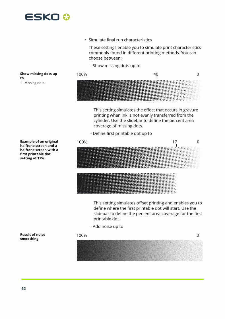
• Simulate final run characteristics
These settings enable you to simulate print characteristics commonly found in different printing methods. You can choose between:
- Show missing dots up to
Show missing dots up to1 Missing dots
100% 40 0
1
This setting simulates the effect that occurs in gravure printing when ink is not evenly transferred from the cylinder. Use the slidebar to define the percent area coverage of missing dots.
- Define first printable dot up to
Example of an original halftone screen and a halftone screen with a first printable dot setting of 17%
100% 17 0
This setting simulates offset printing and enables you to define where the first printable dot will start. Use the slidebar to define the percent area coverage for the first printable dot.
- Add noise up to
Result of noise smoothing
100% 0

Settings in System Manager 4
This setting produces an image which more closely resembles output on a printing press. It creates a less smooth effect than an inkjet printout. Use the slidebar to define the amount of noise smoothing.
4.3.3 Output device settings
The output device settings are available when you select anoutput device in the layout area.
• Device tab > Information pane
• Name
Type a name for a new output device or change the name of an already defined output device. It is not possible to change the name of the linearization device.
• Description
Type a brief description, if required.
• Manufacturer
Select the manufacturer of your output device.
• Device type
Select your printer model from the drop-down list.
Profiles are provided with your software and saved to the Profiles folder. If no profiles are located in this folder, an error message to this effect will be displayed when you select a device type and you will not be able to set up your printer.
63

64
• Device tab > Connection pane
• Connection type
- Print via IP network
Select this option to print to a network printer.
Type the IP address of the network printer in the edit box.The printer’s TCP/IP address may be a defined name or a series of numbers, e.g. 10.1.149.33. Ask your system administrator if you are not sure of your printer’s TCP/IP address.
Click Test to check that a connection to the printer has been properly established. To test the connection, the printer must be switched on. If you receive an error message, consult your system administrator for advice.
Used TCP/IP protocol is: Select the type of TCP/IP protocol that your printer uses for data transfer.
Select “RAW on port” if your printer supports RAW printing. Most printers support RAW printing to port 9100. However, please note that this setting depends on the network settings made at the printer and may, therefore, be different.
Select “LPR queue” if your printer supports LPR printing. Then type the queue name in the edit box. It is normally only necessary to type a queue name if you are printing via a Unix system or a print server with multiple interfaces. Therefore, in most cases, you can leave this edit box blank. Please refer to your printer manual for further information.
- Print via port
Select this option and choose the name of your printer from the drop-down list to print to a printer that is connected via USB to the Server computer. The printer must be switched on when you start Esko Proof. Otherwise, it will not be automatically detected.
• Media tab > Print Configuration pane
• Ink type
Select the type of ink that is inserted in your printer.
Settings in System Manager 4
• Media name
Select the name of the media you will be printing on.
If you select a media type that is patched to a Device Link profile, Esko Proof will indicate this.
A Device Link profile represents a fixed combination of printer and media type.
Device Link profiles must be saved to the folder where the media profiles are saved. Otherwise they cannot be detected in Esko Proof.
• Calibration set
This area displays the epl base linearization which is patched to the selected media type. If more than one epl is available, you can select which one you want to use from the drop-down list.
By clicking “Catalog” you can display a list of all the epl files available for the selected media name and view the printer conditions under which they were created.
Click “New Linearization and Profile...” to open Esko LinTool if you want to create a new base linearization.
The current printer settings are automatically transferred to the linearization device. In other words, the default or previously made settings of the linearization device will be overwritten.
• Visual correction
If you have created a visual correction file, you can select it here.
65

66
• Media tab > Media Setting pane
• Media size correction
This feature lets you correct any inconsistency in the length of the printed image. This may occur as a result of the particular combination of printer and media that you are using.
Normally, job length and printed image length are the same. However, if you discover that your printed image is longer or shorter than it should be, you can adjust the output length.
The file Lineal_01.ps is provided in the Samples folder for this purpose. The printed image displays a set of ruler markings 0.5 m x 0.5 m. Print out the file and measure the length of the ruler markings. If the measurement is not accurate, you can compensate for the difference by typing the target length and the actual measured length in the appropriate edit boxes.
This setting is independent of the hardware setting available at the control panel of some printers.
• Media size
- Source
Select the type of media feed, e.g. roll or single sheet. This setting is printer-dependent and varies according to the types of media feed and number of media trays installed for your particular printer.
- Format
Select the size of the media inserted in the printer from the drop-down list.
If your media size is not listed, you can define a custom format. Type the desired Width and Height in the edit boxes and click Save. A dialog opens to let you define a name. When you close the dialog, your custom format is automatically selected.
Esko Proof uses the default system of measurement set up in the operating system — centimeters, millimeters or inches. However, you may change this setting if you wish.
To delete a custom media format, select it and click Delete. It is not possible to delete default media formats.

Settings in System Manager 4
See also:
“Edit menu” on page 30
• Special tab > Special Printer Settings paneThis pane provides printer-specific settings. Please refer toyour printer documentation if you require further informa-tion.The settings that you make in Esko Proof override the settingsof the same name that are made at the printer.For example, you may have the following settings:
• Autocut feature
• Media suction
• Printer dryer function
• Dry time definition
• Borderless printing
To achieve borderless printing you must also select the page layout setting “Fit to page size”.
• Measurement settings for verification (ILS30)
Select the measurement condition to use when measuring verification strips with your ILS30 inline spectrophotometer:
- M0
The UV content of the speciment illumination is not defined. Measuring occurs in one step.
- M1
The UV content of the specimen illumination is defined as D50. Measuring occurs in two steps.
- M2
Requires that the spectral power distribution of the speciment illumination is in the wavelength range of 420 nm to 700 nm, with no substantial radiation power in wavelengths below 400 nm. Corresponds to UV cut. Measuring occurs in two steps.
67

Chapter 5: Managing system workflows
5.1 Making changes to system workflows
64
A fully online system workflow is indicated by green arrowsfrom user through to output device. A red rectangle indicatesthat the workflow has been interrupted at a certain stage.To stop a workflow, click on a green arrow in the workflow sys-tem. The green arrow changes into a red rectangle to indicatethat the workflow has been interrupted.
Setting system workflows online/offline1 Online2 Offline
1 2
Occasionally, you may want to make alterations to an existingsystem workflow, e.g.:
• To add or delete a user
• To change workflow settings
• To connect to a different printer or service an output deviceIn order to make changes to a system workflow, you must firststop the workflow at the appropriate stage of job processingto prevent jobs from entering a workflow that is temporarilyunavailable.You can stop a system workflow:
• at the user (to prevent a user logging on)
• at workflow entry (to prevent automatic job detection, i.e. hotfolders are no longer monitored)
• at workflow exit (to prevent jobs from being processed by Esko Proof. Stopping the workflow at this stage is the equivalent of loading an on-hold job)
• at the output device (to prevent jobs from being printed)
5.1.1 Available menu commands
Context menus are available for users, workflows and outputdevices which make it easy to manage your system workflows.

Managing system workflows 5
• User settings
• Connected Workflows
Choose this command and choose a workflow from the submenu to connect the user to a specific workflow.
• User is online/offline
This command shows whether a selected user is logged on to Esko Proof. In addition, you can use this command to connect or disconnect a user from his workflows.
• Connect to All Workflows
Choose this command to connect the user to all available workflows.
• Disconnect from All Workflows
Choose this command to disconnect the user from all workflows.
• New User
Choose this command to add a new user.
• Delete User
Choose this command to delete the user.
• Color Indicator
Choose this command to assign a color to the user.
• Workflow settings
• Connected Users
Choose a user from the submenu to connect him to the workflow.
• Connected Output Device
Choose an output device from the submenu to connect the workflow to a specific output device. Each workflow can only be connected to one output device.
• Workflow Accepts New Jobs
Choose this command to switch the workflow online so that jobs can be received from users. If a workflow is already online to users, this is indicated by a check mark.
65

66
• Workflow Processes and Prints Jobs
Choose this command to switch the workflow online/offline to the output device. If a workflow is online to an output device, this is indicated by a check mark. In an offline status, jobs are processed but not submitted to the output device.
• Connect All Users to Workflow
Choose this command to connect all users to the workflow.
• Disconnect All Users from Workflow
Choose this command to disconnect all users from the workflow.
• Disconnect Output Device
Choose this command to disconnect the output device from the workflow.
• Save as Environment
An environment is a combination of workflow and printer. Choose this command to create a backup copy of your workflow and printer settings.
• New Workflow
Choose this command to select a workflow template and create a new workflow.
• Delete Workflow
Choose this command to delete the workflow. The workflow must be completely offline.
• Color Indicator
Choose this command to assign a color to the workflow.
• Output device settings
• Connected Workflows
Choose a workflow from the submenu to connect it to the output device.
• Device is Online
Choose this command to switch the output device online/offline. The output device must be online to output print jobs.

Managing system workflows 5
• Connect Output Device to All Workflows
Choose this command to connect all available workflows to the output device.
• Disconnect Output Device from All Workflows
Choose this command to disconnect all workflows from the output device.
• New Output Device
Choose this command to add a new output device.
• Delete Output Device
Choose this command to delete the output device. The output device must first be disconnected from all workflows.
• Color Indicator
Choose this command to assign a color to the output device.
See also:
“Special tab > Special Printer Settings pane” on page 67
5.2 Saving and restoring settings
Setting up workflows for your exact needs can be quite time-consuming. For this reason, Esko Proof offers you the oppor-tunity to save settings in a backup file.In Esko Proof, there are two types of backups: system config-uration and environment settings.
67

68
• System configuration
This is useful if you need to reinstall the software at any time. It saves:
- All user settings
- All workflow settings, including selected presets, linearization files and spot color tables, but no profiles.
- All printer setups
• Environment settings
This is useful if you output repeat jobs at regular intervals and need to be sure that you use exactly the same settings each time. Environment backups also enable you to provide customers with exact workflow/printer information.
An environment saves:
- All workflow settings, including selected profiles, presets, linearization files and spot color tables
- The printer setup, excluding the port configuration
You can save an environment for:
- a workflow selected in System Manager
- a job selected in Job Explorer
TO SAVE SYSTEM CONFIGURATION SETTINGS
1 From the File menu in System Manager, choose Backup.
The Esko Proof Backup dialog opens.

Managing system workflows 5
Esko Proof Backup Dialog
2 Select the check boxes of the items you wish to back up.
All system configuration settings are automatically saved by default.
3 Define a backup location.
System configuration files are saved to two locations: the default Backup folder, and a freely definable destination, e.g. desktop. To define a different destination, click Select and browse to the required location.
4 Click Save.
A window opens when the backup has been successfully completed.
5 Click OK to complete the backup procedure.
TO RESTORE A SYSTEM CONFIGURATION
1 From the File menu in System Manager, choose Restore.
The Backup window opens to display the backup files located in the Backup folder.If you restore a system configuration after deleting and rein-stalling Esko Proof, this folder is empty. In this case, clickChoose and browse to the location of the second backup file.Unless defined otherwise during the backup procedure, youwill find the second file on the desktop of your computer.2 Select the backup file to be restored.
69

70
3 Click OK.
A window opens when the restore has been successfully completed.
4 Click OK.
You need to restart the Server to view your restored system configuration.
TO SAVE AN ENVIRONMENT
1 Save a workflow or job environment by:
• Choosing File > Save as Environment
• In System Manager, right-clicking on a workflow in the layout area and choosing Save as Environment from the context menu, or
• In Job Explorer, right-clicking on a job in the job list and choosing Save as Environment from the context menu
The dialog Save as Environment opens. If you are saving a workflow environment, the workflow settings are displayed. For a job environment, the edit box is empty to enable you to type your own job information.
Dialog Save as Environment
2 Define a backup location.
Environment backup files are saved to two locations: the default Environments folder, and a freely definable destination, e.g. desktop. To define a different destination, click Choose and browse to the required location.

Managing system workflows 5
3 Click Save.
Environment names are assigned automatically by Esko Proof. Job environments are made up of the file name and the output device. Workflow environments indicate the workflow name, the output device and the creation date.
If an environment name already exists, you are asked whether you want to overwrite the original file with the new settings.
A window opens when the backup has been successfully completed. Environments files have the file extension *.xfe.
4 Click OK to complete the backup procedure.
TO RESTORE AN ENVIRONMENT
Environments can only be restored in System Manager.1 Import an environment by:
• Right-clicking on an empty part of the layout area and choosing Import Environment from the context menu, or
• Choosing File > Import Environment
The Import Environment window opens to display the backup files located in the Environments folder.If this folder is empty, click Choose and browse to the locationof the second backup file. 2 Select the backup file to be restored.3 To allow saved files and profiles of the same name to be overwritten, select the check box “Allow overwriting”.
If you leave this check box unchecked, only files with unique names are restored.
4 Click OK to restore the environment.
The Esko Proof Information window opens when the restore has been successfully completed.
5 Click OK.The restored environment can be seen in System Manager.
• If an appropriate output option license is available, workflow and output device are restored and connected. However, the printer port setting is reset to its default value, so you must set up a connection before you can print.
71

72
• If an insufficient number of appropriate output option licenses is available, workflow and output device are restored, but not connected.
• If no appropriate output option license is available, the workflow is restored, but not the output device.

Managing system workflows 5
73

Chapter 6: Settings in Job Explorer
6.1 Menus
6.1.1 File Menu
74
• Import Job
Choose this command to load a job.
• New Nesting
Choose this command to create a nesting of one or more loaded jobs.
By clicking “All Jobs” at the bottom of the Selector, you can create nestings from jobs loaded in different workflows.
• Save
Choose this command to apply changes you have made to a job. If you do not choose this command, your job settings will not be saved and the job will be processed using the previous settings.
• Save as Environment
An environment is a combination of workflow and printer. Choose this command to create a backup copy of your workflow and printer settings.
Choose this command to save the current settings and start printing.
• Cancel
Choose this command to cancel processing.
• Login
Choose this command to display the “Login” dialog. This command enables you to log in under a different user name or to log on to a different Server.
• Logoff and Exit
Choose this command to log off and exit the Esko Proof Client. The next time you start Esko Proof the “Login” dialog opens.

Settings in Job Explorer 6
• Exit
Choose this command to exit Esko Proof. The next time you start Esko Proof you will automatically be logged on with the same user data.
In the Macintosh version of the software, you will find the command in the Esko Proof menu.
6.1.2 Edit menu
Most commands in this menu are also available if you right-click on an image in the preview window.• Select
Choose the command “All” to select all the pages of a nesting. Choose “Page Below”/”Page Above” to select the page that was inserted into the nesting immediately before/after the currently selected page. “None” deselects all selected pages.
• Cut
Choose this command to remove a selected page from a nesting. The page is saved to the clipboard and can be reinserted using the command “Paste”.
• Copy
Choose this command to copy a selected page from a nesting. The page is saved to the clipboard and can be copied as many times as required using the command “Paste”.
• Paste
Choose this command to insert a page that you have previously copied or removed from a nesting using the command “Copy” or “Cut”.
• Delete
Choose this command to delete a job, including nested pages. You can also use this command to delete individual copies of an image. However, if you delete the original image, all copies will be deleted.
• Print & Cut
Choose this command to send the selected job to your print and cut device (that prints the job and cuts the contour data).
75

76
• Preview
Choose this command to save the current settings, including those not displayed on the fly, and force a preview of an image. This is useful for workflows for which the setting “Create preview before RIPing” is not activated by default.
• Placed
Choose this command to place or remove a page in a nesting (and the nesting preview). By selecting the nesting file, you can place or remove all files in the nesting at once.
• Locked
Choose this command to set a nested page at its current settings and position on the sheet. A locked page cannot be modified, nor can it be rearranged on the sheet.
• Remove from Nesting
Choose this command to remove a job from a nesting. A separate job is created in the job list of the same workflow.
• Order
Choose this command to alter the order of overlapping pages in a nesting. You can move a selected page to the front or back of the stack or move it up or down a level. This function can also be performed on multiple file selections.
To select multiple pages, hold down the <Shift> key.

Settings in Job Explorer 6
• Align
Choose this command to define an alignment for selected pages in a nesting. Pages can be aligned according to their upper, lower, left or right edges or according to their vertical or horizontal centers.
To select multiple pages in the preview simultaneously, hold down the <Shift> key. to select multiple pages in the job list, use the <Ctrl> key
Randomly positioned images
Aligned upper edges ...
77

78
• Distribute
Choose this command to distribute selected pages on a nesting. Pages are rearranged evenly on the sheet so that their center points are equidistant from each other. You can distribute pages according to their upper, lower, left or right edges or according to their vertical or horizontal centers. This feature is primarily intended for use in conjunction with the align feature.
To select multiple pages simultaneously, hold down the <Shift> key.
... and horizontal centers distributed

Settings in Job Explorer 6
• Scale
Choose this command to enlarge or reduce the size of an image.
- No Scaling
This setting returns a previously scaled image to its default size.
- Percentual
Select a scale factor from the submenu.
The applied scale factor is indicated by a check mark next to the appropriate setting.
You can also scale an image by selecting it in the preview window and dragging the mouse or using the transform tools.
- Fit to
Choose “Page”, “Sheet Width” or “Sheet Height” from the submenu.
Scaling to page size will enlarge the image to either the width or the height of the media. The image keeps its original proportions and scaling does not exceed the sheet format, i.e. no cropping takes place.
Scaling to sheet width or sheet height will scale the image to the width or height of the sheet respectively.
Be careful when scaling to sheet height or fitting to sheet if you are printing on a roll substrate. Esko Proof calculates the image length based on a new roll of substrate (usually 15 m).
- Scale Proportionally
Choosing this command enables you to scale the width and height of an image proportionally. Select an image by one of the corner handles and drag the mouse until the required image size is reached.
79

80
• Rotate
- Rotate 0, 90, 180 or 270 degrees
Choose this command to rotate an image by the selected angle.
You can also rotate a selected image by moving the cursor next to (but not directly onto) one of the handles. The cursor form changes, enabling you to rotate the image as required. When you release the cursor, the image will automatically snap to the nearest 90 degree angle of rotation. Alternatively, you can use the transform tools.
- Flip Horizontally
Select this command to create a mirror image by flipping a selected image on its vertical axis.
You can also flip an image using the transform tools.
- Flip Vertically
Select this command to create a mirror image by flipping a selected image on its horizontal axis.
You can also flip an image using the transform tools.
• Reset Page
If you are not satisfied with your job changes, you can use this command to return the page to its original state.
• Clone
Use this command to clone a page of your nesting.
After clicking Clone, the Clone Image dialog box appears. Enter the number of clones you want to create, and click Clone It! (creating a single clone is similar to copying and pasting the original page).
The cloned pages are placed in the nesting, but are not automatically arranged. You can apply individual job settings to each clone. However, if you delete the original, all the clones are also deleted.
• Remove Clone
Use this command to delete a cloned page.

Settings in Job Explorer 6
• Languages (Windows only)
Choose this command to change the language in which the user interface is displayed. You must restart the Esko Proof Client before the new language takes effect. By default, the language of the operating system is displayed.
On a Macintosh, you can change the language via the international settings in “System Preferences”.
To display one of the supported Asian languages on a PC, Esko Proof must be running on an operating system that supports 2-byte fonts.
• Measurement System
Choose this command to define which system of measurement is used in Esko Proof. The default setting corresponds with the system of measurement set up in the operating system. However, you can choose between millimeter, centimeter, meter, inch and foot.
• Monitor Profile
Esko Proof provides you with the opportunity to verify color accuracy on a computer screen. This is known as “soft proofing”. However, much like the color output of each printer can vary greatly, so each monitor displays color slightly differently. To overcome this problem, it is important that the monitor is regularly calibrated to a certain standard. Monitor calibration consists of two steps:
- adjusting the brightness and control settings on the monitor itself to set values and
- creating a monitor profile, which defines the white point, gamma and RGB phosphor settings
Windows and Macintosh computers provide standard monitor profiles as part of the operating system software. In Esko Proof you can select a monitor profile that you have created yourself or one provided with the operating system.
• Copy to Workflow
Choose this command to copy a job from one workflow to another.
81

82
• Move to Workflow
Choose this command to transfer a job from one workflow to another.
• Copy to Printer
Choose this command to copy a job from one workflow to another.
• Move to Printer
Choose this command to transfer a job from one output device to another.
See also:
“Transform tools” on page 89
“Keyboard shortcuts” on page 93
6.1.3 Nesting menu
The commands in this menu are also available if you right-clickanywhere outside a nested job in the preview window.• New Sheet
Choose this command to add a new sheet to an existing nesting. A sheet is the physical size of the media you have defined either for the printer (Output Device > Media) or as a sheet (Layout > Sheet).
• Delete Sheet
Choose this command to delete a sheet from a nesting.To delete the final sheet, use the Edit > Delete command.
• Go to
Choose this command to scroll through a multi-sheet nesting. You can scroll backward and forward through individual sheets or proceed directly to the first or last sheet of a nesting.
• Apply
Choose this command to rearrange the pages of a nesting after you have made changes. This command corresponds to the button of the same name found on the “Nesting” pane of the “Layout” tab in the Property Inspector.

Settings in Job Explorer 6
6.1.4 Tools menu
• Esko VerificationChoose this command to start Esko Verification (if you have a license for it), a tool to verify your printer’s color accuracy.
• System Manager (users with administrative rights only)
Choose this command to switch to System Manager.
• System Information
Choose this command to display information about the resources used and the jobs processed by the Esko Proof Server.
6.1.5 View menu
• Zoom inChoose this command to enlarge the size of the preview.
• Zoom out
Choose this command to reduce the size of the preview.
• Fit to
Choose this command to modify the preview view.
- Window
This setting scales the sheet so that it is completely visible in the preview window.
- Selection
This setting scales a selected image or page to the size of the preview window.
- Width
This setting scales the sheet so that its whole width fits in the preview window.
- Height
This setting scales the sheet so that its whole height fits in the preview window.
- Actual Size
This setting scales the sheet and all inserted pages to their actual size.
83

84
• Clear Guides
Guides appear as non-printing lines and help you to layout pages on your nesting sheet. Choose this command to delete guides that you have previously placed.
You can also delete a guide by dragging it to the ruler. Drag horizontal guides to the horizontal ruler and vertical guides to the vertical ruler.
To place a guide, you must first display the rulers. From the “View” menu, choose “Visual aids” and select “Rulers” from the submenu.
To create a horizontal guide, hold down the mouse button on the horizontal ruler and drag to the desired position on the sheet. To create a vertical guide, drag from the vertical ruler. Please note that guides are not saved. When you exit Esko Proof, all guides are automatically deleted.
To move a guide, move the cursor over the guide until the x or y coordinate appears. Then, hold down the mouse button and drag the guide to a new position. Please note that it is not possible to move locked guides.
• Lock Guides
Choose this command to lock guides in a fixed position.
• Snap to
Choose this command to ensure precise image alignment. When this command is activated, guides, grid or objects receive a magnetic property which causes images in their proximity to snap to them.
When “snap to objects” is selected, the setting for “Spacing between nesting elements” is observed.

Settings in Job Explorer 6
• Visual Aids
This command contains a number of sub-commands to help you lay out your nesting.
- Rulers
Choose this command to show or hide the horizontal and vertical rulers. The unit of measurement used is defined on the “Edit” menu.
You can change the zero coordinates (0, 0) by pressing and holding down the left mouse button on the top left of the preview window (where the vertical and horizontal rulers intersect) and dragging the mouse to the required position.
To reset the zero coordinates, double-click on the intersection of the rulers in the top left corner of the preview window.
- Guides
Choose this command to show or hide the guides.
- Grid
The grid is a set of evenly spaced non-printing horizontal and vertical lines that helps you to layout pages on a sheet. Choose this command to show or hide the grid. The grid spacing is fixed, but adapts automatically according to the selected zoom factor.
- Tiles
Choose this command to show or hide the tiles on the image.
- Marks
Choose this command to show or hide applied crop marks.
- Page Frame
Choose this command to draw a black frame around each page on the sheet. You may find this useful to see the page borders, e.g. to check if an object on a page has a lot of white space around it which may be overlapping other images.
- Overlaps
85

86
Choose this command to check if pages are overlapping. Overlapping pages are indicated by a red frame.
- Sheet Margins
Choose this command to display the non-printable margins as defined by the printer's firmware.
- All
Choose this command to select all the visual aids on this menu in one step.
- None
Choose this command to deselect all the visual aids on this menu in one step.
• Maximize Preview
Choose this command to display an enlarged view of the preview window. Choose it again to revert to the default Job Explorer window.
• Show Job Content Only
Choose this command to fit the preview on the job image.
6.1.6 Workspace menu
• Property TabsThis displays the tabs available in the right pane. To hide a tab, click an item that has a check mark next to it.
To show a hidden tab, click an item that does not have a check mark next to it. To show all hidden tabs, click All.
6.1.7 Help menu
• HelpChoose this command to start the online Help for Esko Proof.
• About
Choose this command to open a window with details of your program version.
In the Macintosh version of the software, you will find the command in the Esko Proof menu.
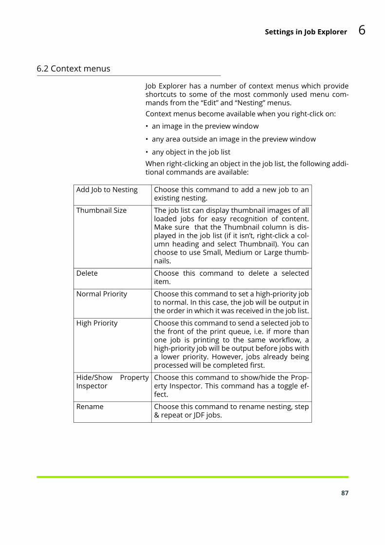
Settings in Job Explorer 6
6.2 Context menus
Job Explorer has a number of context menus which provideshortcuts to some of the most commonly used menu com-mands from the “Edit” and “Nesting” menus.Context menus become available when you right-click on:
• an image in the preview window
• any area outside an image in the preview window
• any object in the job listWhen right-clicking an object in the job list, the following addi-tional commands are available::
Add Job to Nesting Choose this command to add a new job to anexisting nesting.
Thumbnail Size The job list can display thumbnail images of allloaded jobs for easy recognition of content.Make sure that the Thumbnail column is dis-played in the job list (if it isn’t, right-click a col-umn heading and select Thumbnail). You canchoose to use Small, Medium or Large thumb-nails.
Delete Choose this command to delete a selecteditem.
Normal Priority Choose this command to set a high-priority jobto normal. In this case, the job will be output inthe order in which it was received in the job list.
High Priority Choose this command to send a selected job tothe front of the print queue, i.e. if more thanone job is printing to the same workflow, ahigh-priority job will be output before jobs witha lower priority. However, jobs already beingprocessed will be completed first.
Hide/Show PropertyInspector
Choose this command to show/hide the Prop-erty Inspector. This command has a toggle ef-fect.
Rename Choose this command to rename nesting, step& repeat or JDF jobs.
87

88
See also:
“Edit menu” on page 75
“Nesting menu” on page 82
6.3 Toolbars
6.3.1 First toolbar
Import JobClick this button to load a job.Create NestingClick this button to create a nesting of one or more loadedjobs.SaveClick this button to save the current settings.PrintClick this button to start printing.Print & CutClick this button to send the selected job to your print and cutdevice (that prints the job and cuts the contour data).Cancel PrintingClick this button to cancel printing.Delete JobClick this button to delete the selected job from the job list.Esko Verification:Click this button to start Esko Verification (if you have a licensefor it) — a tool for verifying the colors on your proof.6.3.2 Second toolbar
Zoom Factor:Click the arrow button to increase or reduce the size of thepreviewed image and select a zoom factor from the drop-down list. You can also choose to display a preview that equalsthe size of the preview window, the size of the selected area orthe width, height, or actual size of the image. Alternatively,type a scale factor in the edit box.See also:
“Fit to” on page 83

Settings in Job Explorer 6
Zoom:Click this button to zoom in on the preview. Select the tool andclick inside the preview window. To deselect the zoom func-tion, click the transform job icon in the first toolbar.Scroll buttons:These buttons enable you to scroll forwards and backwardsthrough a multi-page document or a multi-page nesting.Order:Click the arrow to the right of this button to alter the order ofoverlapping pages in a nesting. You can move a selected pageto the front or back of the stack or move it up or down a level.This function can also be performed on multiple page selec-tions. To select multiple pages simultaneously, hold down the<Shift> key.Align:Click the arrow to the right of this button to define an align-ment for selected pages in a nesting. Pages can be aligned ac-cording to their upper, lower, left or right edges or accordingto their vertical or horizontal centers. To select multiple pagessimultaneously, hold down the <Shift> key.Transform JobClick this button to display the transform tools.Crop JobClick this button to display the crop tools.IThe remaining buttons on this toolbar vary according towhether the transform tool or the crop tool is selected.
• Transform toolsIf the transform tool is selected, the following buttons becomeavailable on the second toolbar:Position ImageUse these edit boxes to position an image at precise coordi-nates. The defined coordinates refer to the top left corner ofan image. If multiple pages are selected, the relative positionof the pages to each other remains constant.Width and heightUse these edit boxes to modify the width or height of an im-age. Enter the values using the system of measurement de-fined on the Edit menu. Press <Enter> or <Tab> for the changeto take effect. If multiple images are selected, the scaling is ap-plied to the image that is nearest to the top left corner of thesheet. All other images are scaled in proportion.To enter a scaling factor as a percentage, click the button“Scale percentually”.
89

90
Scale Percentually:If you click this button, you can type in a scaling factor forwidth and height as a percentage.Scale Proportionally:Click this button to ensure that the width and height of yourimages are scaled proportionally. If you modify the width of animage, the height will automatically change to maintain theoriginal proportions.Rotation Angle:Select an angle of rotation from the drop-down list. Angles of0, 90, 180 and 270 degrees are possible.Flip Horizontally:Click this button to create a mirror image by flipping a selectedimage on its vertical axis.Flip Vertically:Click this button to create a mirror image by flipping a selectedimage on its horizontal axis.Reset Transformations:Click this button to return an image to its original untrans-formed state.Lock:Click this button to fit a nested page at its current setting andposition on the sheet. A locked page cannot be modified, norcan it be rearranged on the sheet.
• Crop toolsThe crop tools enable you to define and output a specific areaof an image, without printing the whole image.If the crop tool is selected, the following buttons become avail-able on the second toolbar:Define cropped image sizeThe edit boxes show the current image size. If you type in newdimensions, the image is cropped along the bottom and rightedges.Define cropped margin width:Use these edit boxes to crop the top, bottom, left or right mar-gins of an image.Reset:Click this button to return an image to its original uncroppedstate.

Settings in Job Explorer 6
6.4 Property Inspector
The Property Inspector of Job Explorer displays the settingsmade for the workflow in System Manager. In addition, somejob-specific settings are possible which override the corre-sponding workflow settings for that particular job.Many of the settings are identical to the settings that have pre-viously been defined for the workflow. Therefore, this sectiondescribes only the differences.
6.4.1 File tab > Source File Information pane
The Source File Information pane displays job-specific infor-mation, such as the name of the selected file, together withdetails of the date the file was created and by whom.It also contains information about the size of the original file(in centimeters or inches and dpi) and states whether the im-age file is composite or in-RIP separated.It also shows which device the job was or will be printed on,and nesting information if applicable.
6.4.2 File tab > Warning and Error pane
Esko Proof displays warning messages, for example to let youknow if a page will be cropped during printing.If an error occurs during job processing, a message displaysthe cause of the problem.
6.4.3 File tab > Subfiles pane
In the case of multiple file jobs, the names of the individualfiles which make up the job are listed.
6.4.4 File tab > Job Merge pane
You can use this pane to merge jobs manually.1. In the job list, click the job that will be the master (back-
ground) job.2. Select the check box at the top of the Job Merge pane,
then select Master job and save your changes.3. In the job list, click the (content) job that will be superim-
posed on the master job.4. Select the check box at the top of the Job Merge pane,
then select Content job. In the Assign master job list, se-lect your master job, and save your changes.
6.4.5 File tab > PS/EPS/PDF pane
The PS/EPS/PDF pane displays job information specific to aloaded PS/EPS/PDF file. If a job in any other file format is load-ed, this pane is not visible.
6.4.6 Layout tab > Virtual Sheet Size pane
The settings on this pane are identical to the settings of thesame name available in System Manager.
91

92
See also:
“Layout tab > Virtual Sheet Size pane” on page 49
6.4.7 Layout tab > Layout Options pane
The settings on this pane are identical to the settings of thesame name available in System Manager.
See also:
“Layout tab > Layout Options pane” on page 49
6.4.8 Layout tab > Nesting pane
This tab enables users with no administrator rights to definebasic settings which affect media consumption, such as rota-tion and spacing between nesting objects.All the settings made to nested pages on this tab must be “con-firmed” by clicking Apply. In addition to rearranging the pagesin accordance with the new settings, the Apply button alsosaves your changes.
See also:
“Layout tab > Nesting pane” on page 53
6.4.9 Layout tab > Step & Repeat pane
This pane enables you to create a manual step & repeat.You must click Apply for the settings to take effect.Step & repeat jobs receive the name “StepAndRepeat”, fol-lowed by a consecutive number, e.g. StepAndRepeat_66. Youcan rename step & repeat jobs by selecting the job and choos-ing Rename from the context menu.Only original images can be selected and edited. Therefore,make sure that your image is scaled to the required size, etc.before performing step and repeat.After stepping and repeating, the original image is markedwith a lock icon to indicate that the image can no longer be ed-ited.
“Layout tab > Step and Repeat pane” on page 55
6.4.10 Layout tab > Job Ticket pane
The settings on this pane are identical to the settings of thesame name that are available in System Manager.
See also:
“Layout tab > Job Ticket pane” on page 56
6.4.11 Finishing tab > Crop Marks pane
The settings on this pane enable you to choose job-specificcrop marks. The settings are identical to the settings in SystemManager.

Settings in Job Explorer 6
See also:
“Finishing tab > Crop Marks pane” on page 59
6.4.12 Output tab > Print Settings pane
The same settings are available as in System Manager.
See also:
“Output tab > Print Settings pane” on page 60
6.4.13 Output tab > Media Settings pane
The same settings are available as in System Manager.
See also:
“Media tab > Media Setting pane” on page 66
6.4.14 Output tab > Media Configuration pane
The same settings are available as in System Manager.This pane also enables you to apply a different media set to aselected job. Media sets are created for a specific combinationof settings, e.g. for a particular type of media or for a certaintype of ink.“Media tab > Print Configuration pane” on page 64
6.4.15 Output tab > Advanced Print Options pane
The same settings are available as in System Manager.
See also:
“Output tab > Advanced Print Options pane” on page 61
6.4.16 Output tab > Special Printer Settings pane
The same settings are available as in System Manager.
See also:
“Special tab > Special Printer Settings pane” on page 67
6.4.17 System tab > Device pane
This pane displays the name and type of the connected outputdevice.For some specific printers (for example, HPZ and Epson x900printers), Esko Proof supports remote printer monitoring andcan retrieve certain information from the printer and displayit on this pane. On this pane, you can also check the currentprinter status.
6.5 Keyboard shortcuts
Key combinations are available in Job Explorer. They mostlycorrespond to the shortcuts that you are already familiar withfrom popular graphics programs.
93

94
Many of the key combinations that can be applied to individu-al images can also be applied to multiple job selections on anesting.
6.5.1 Activating options
Function Function key
Start Esko Verification • <F3>
• <Alt>+<Apple>+<F3>
6.5.2 Activating toolbars
Function Function key
Transform toolbar <T>
Crop toolbar <C>
Edit tiling toolbar <E>
Zoom toolbar <Z>
6.5.3 General
Function Key combination
Switch between Job Explorer and System Manager
• <F6>
• <Alt>+<Apple>+<F6>
Show system information • <F10>
• <Alt>+<Apple>+<F10>
Show context menu for a selected page (“Edit” menu)
Right-mouse click on a page
Show context menu for a selected sheet (“Nesting” menu)
Right-mouse click on a sheet
Show context menu (“View” menu)
<Shift>+right-mouse click on a sheet
Select page Click on page
Scale page(s)(Crop tool selected)
Click on page handle. Then press <Alt> and drag cursor.
Crop page(s)(Transform tool selected)
Click on page handle. Then press <Alt> and drag cursor.
Rotate page(s) Click on page edge and drag image. Rota-tions snap automatically to 90°, 180°, 270° or 360°.
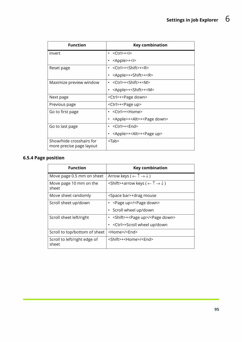
Settings in Job Explorer 6
Invert • <Ctrl>+<I>
• <Apple>+<I>
Reset page • <Ctrl>+<Shift>+<R>
• <Apple>+<Shift>+<R>
Maximize preview window • <Ctrl>+<Shift>+<M>
• <Apple>+<Shift>+<M>
Next page <Ctrl>+<Page down>
Previous page <Ctrl>+<Page up>
Go to first page • <Ctrl>+<Home>
• <Apple>+<Alt>+<Page down>
Go to last page • <Ctrl>+<End>
• <Apple>+<Alt>+<Page up>
Show/hide crosshairs for more precise page layout
<Tab>
Function Key combination
6.5.4 Page position
Function Key combination
Move page 0.5 mm on sheet Arrow keys ( ← ↑ → ↓ )
Move page 10 mm on the sheet
<Shift>+arrow keys ( ← ↑ → ↓ )
Move sheet randomly <Space bar>+drag mouse
Scroll sheet up/down • <Page up>/<Page down>
• Scroll wheel up/down
Scroll sheet left/right • <Shift>+<Page up>/<Page down>
• <Ctrl>+Scroll wheel up/down
Scroll to top/bottom of sheet <Home>/<End>
Scroll to left/right edge of sheet
<Shift>+<Home>/<End>
95

6.5.5 Nesting jobs
Function Key combination
Select all jobs • <Ctrl>+<A>
• <Apple>+<A>
Add page to selection <Shift>+click on page
Select jobs in a cropped area Mouse click and drag lasso
Remove page from selection <Shift>+click on page
Move selected pages Drag cursor
Remove selected page(s) and copy to clipboard (cut page)
• <Ctrl>+<X>
• Apple+<X>
Delete selected page(s) <Ctrl>+<Backspace>
Copy selected page(s) • <Ctrl>+<C>
• <Apple>+<C>
Paste selected page(s) from the clipboard
• <Ctrl>+<V>
• <Apple>+<V>
Refresh nesting • <Ctrl>+<Alt>+<R>
• <Apple><Alt>+<R>
Add sheet • <Ctrl>+<Alt>+<+>
• <Apple><Alt>+<+>
Lock page • <Ctrl>+<L>
• <Apple>+<L>
Unlock page • <Ctrl>+<Alt>+<L>
• <Apple>+<Alt>+<L>
6.5.6 Zoom
Function Key combination
Zoom in/out • <Ctrl>+<+>/<>
• <Apple>+<+>/<>
• <Alt>+Scroll wheel
Fit sheet to window • <Ctrl>+<0>
• <Apple>+<0>
Fit to actual size • <Ctrl>+<Alt>+<0>
• <Apple>+<Alt>+<0>
96

Settings in Job Explorer 6
Fit selection to window • <Ctrl>+<F>
• <Apple>+<F>
Fit selection to window and zoom out one step
• <Ctrl>+<Alt>+<F>
• <Apple>+<Alt>+<F>
Zoom in two steps • <Ctrl>+<Space bar>+mouse click
• <Apple>+<Space bar>+mouse click
Zoom out two steps • <Alt>+<Space bar>+mouse click
Zoom into selected area • <Ctrl>+drag lasso
• <Apple>+drag lasso
Function Key combination
6.5.7 Rulers, guides and grid
Function Key combination
Show/hide ruler • <Ctrl>+<R>
• <Apple>+<R>
Set ruler to new zero coordi-nates
Drag cursor from top left corner of preview window (where vertical and horizontal rulers intersect)
Return ruler to default zero coordinates
Double-click in top left corner of preview window (where vertical and horizontal rulers intersect)
Create guide Drag cursor from ruler
Re-position guide Select and drag guide to new position
Delete guide Drag guide and release in ruler (unlocked guides only)
Show/hide guides • <Ctrl>+<;>
• <Apple>+<;>
Lock/unlock guides • <Ctrl>+<Alt>+<;>
• <Apple>+<Alt>+<;>
Show/hide grid • <Ctrl>+<“>
• <Apple>+<“>
Override snap to <Shift>+drag cursor
97

Chapter 7: Printing and monitoring printjobs
98
Esko Proof can process the following formats: PDF, PostScript,EPS, TIFF, and JPEG. Files in all other formats may be loadedbut receive the job status “Not supported” and cannot be pro-cessed.If the Esko Proof Server computer has too little available harddisk space, you will not be able to load and process print jobsin Esko Proof. If problems arise, please check the amount ofavailable hard disk space.
7.1 Printing directly from Esko Proof
Once a system workflow has been set up, you can print yourfirst job. This section leads you step by step through a practicalexample of how to obtain your first printout.
TO PRINT DIRECTLY FROM ESKO PROOF
1 Make sure that a media is loaded in the printer.

Printing and monitoring print jobs 7
2 Start Esko Proof and display Job Explorer.
Job Explorer
3 Load a job using one of the following methods:
• In the toolbar, click Import Job and browse to your desired file.
• Select File > Import Job and browse to your desired file.
• Right-click the mouse button in the job list, choose Import Job from the context menu and browse to your desired file.
• Use the drag-and-drop function to release a file directly in the job list area.
99

100
4 In the Import to dialog, choose a workflow from the list and select the “Hold Job” check box.
Import to dialog
This means that your job is loaded but not automatically processed in Esko Proof. This gives you an opportunity to make job-specific settings before output, if required.
If your job can be processed and output exactly according to the workflow settings, leave the check box “Hold Job” unchecked. In this case, your job will be output as soon as it is loaded in Esko Proof.
5 Click Import. Your job is loaded in Esko Proof.Alternatively, files can also be copied into a defined hotfolder.In this case, the print jobs are automatically loaded in the as-signed workflow.6 Select your job in the job list.
Depending on the workflow settings, an image preview may or may not be created and displayed.
7 Make any required job-specific settings in the Property Inspector.
Job-specific settings override the workflow settings made in System Manager.
See also:
“Settings in System Manager” on page 28

Printing and monitoring print jobs 7
8 To print your job use one of the following methods:
• In the toolbar, click Print.
• Select File > Print.
• Right-click the mouse button in the job list and choose Print from the context menu.
7.2 Printing via a hotfolder
A hotfolder enables users who do not have Esko Proof in-stalled on their computers to copy print jobs to a centrally lo-cated folder on the network.All jobs placed in the hotfolder are loaded and processed inEsko Proof according to the workflow settings.Hotfolders are normally set up for one particular workflow.However, it is possible to set up a hotfolder to be monitoredby more than one workflow by applying load balancing. In thiscase, jobs that are placed in the hotfolder are diverted auto-matically to the first idle workflow that becomes available.Different workflows printing via the same hotfolder may notnecessarily be configured identically. This can result in unsat-isfactory results if the workflow settings are different or if a dif-ferent printer is connected.
See also:
“Enable load balancing” on page 40
TO CREATE A HOTFOLDER
1 Create or choose the folder that will be your hotfolder.
Do not choose a folder that has been mapped as an internal link (shortcut or alias), and do not create a hotfolder on the desktop.
2 If the Esko Proof Server is installed on Windows, please observe the following (and complete steps 3 to 5):
The Esko Proof Server runs on Windows as a service. To enable Esko Proof to communicate with hotfolders via the network, you need to assign network access rights for the Esko Proof Server by creating a user with administrative rights.
3 In a network environment, you need to set up a folder containing one subfolder.
101

102
• The folder must be set up as a shared folder for the network: right-click the folder and choose Properties from the context menu.
On the Sharing tab, click the Share... button and choose who to share the hotfolder with (either everyone or specific users). In Permission Level, to give those users Read/Write privileges.
Setting up folder sharing in Windows
• The subfolder can then be used as the hotfolder.
4 The user must be given read/write privileges and be logged in to:
• the computer with the Esko Proof Server
• the computer with the hotfolder
5 On the computer with the Esko Proof Server, browse to the hotfolder via My Network Places. 6 In System Manager, select a workflow.7 Set the workflow offline by clicking on the green arrow at workflow entry.

Printing and monitoring print jobs 7
8 On the Input tab, open the General pane and define a hotfolder.
TO PRINT VIA A HOTFOLDER
• Copy print jobs manually into a hotfolder or• Set up a hotfolder as a virtual printer. Setting up a virtual printer enables you to select Esko Proof in the print menu of other applications. Jobs that are submitted for printing in this way are loaded into Esko Proof through the hotfolder.Jobs coming through your hotfolder are then processed ac-cording to the settings of the workflow associated with thehotfolder.
See also:
“Hotfolder” on page 39
“I have set up a hotfolder in a network, but submitted jobs do not appear in the job list. What is the problem?” on page 115
103
Chapter 8: Nestings
8.1 What are nestings?
104
The nesting feature in Esko Proof enables you to output anynumber of files collectively as one single print job.There are two types of nestings: automatic and manual. Auto-matic nesting is defined for a specific workflow in System Man-ager. It ensures that all jobs processed via that workflow areprinted out as part of a nesting job. If a workflow is not set upfor automatic nesting, nestings of chosen jobs can be com-piled manually in Job Explorer.In a workflow set up for automatic nestings, jobs are output assoon as, but not before, a defined state has been reached.Esko Proof arranges them in the nesting in accordance withthe workflow settings and outputs them automatically. Thisgives users the freedom to submit non-urgent print jobs atany time.If a workflow is not set up for automatic nesting, you can cre-ate manual nestings. This gives you full control over which im-ages are grouped together and how they are arranged on anesting and also lets you perform job-specific changes to im-ages before printing.It is possible to output nestings as tiles by defining a sheet sizethat is bigger than the media size set for the printer.

Nestings 8
6
8.2 User interface
User interface
1
2
3
4 5
1 Page on a nesting. Pages can be in any supported file format.
2 A nesting sheet represents the output size. If the defined sheet size exceeds the maximum media size supported by the selected printer, the nesting can be output as a tiling.
3 Click to display all loaded jobs. This enables you to create nestings of jobs from different workflows.
4 Tree view of job list.
5 Sets a page at its current settings and position on the sheet (right-click a column header if you don’t see the “Locked” Column). A locked page (closed padlock) cannot be modified, nor can it be rearranged on the sheet. To make modifications, the page must first be unlocked (open padlock). It is possible to lock single pages of a multi-page document. Clicking the padlock icon locks and unlocks an image.
6 Saves your changes to the nesting. All images are rearranged according to the current settings made on the Nesting pane and the preview is updated.
105
8.3 Creating nestings
106
In System Manager, you can set up automatic nesting work-flows. All jobs loaded in Esko Proof are automatically nested.In Job Explorer, you can create manual nestings of selectedjobs.
8.3.1 Automatic nestings
In a workflow set up for automatic nestings, printing starts au-tomatically as soon as one of the following criteria has beenreached:• The defined length of time has elapsed since the last job was loaded.
This setting has priority over the other auto-nesting settings, e.g. a nesting will be printed after the set period even if the minimum percentage of the sheet or line has not been filled.
• The defined percentage of the sheet area has been filled
• The defined percentage of a line has been filled
TO CREATE A WORKFLOW FOR AUTOMATIC NESTING
1 Log on to Esko Proof as a user with administrative rights.2 In System Manager, click the Layout tab and open the Nesting pane.3 Select the “Nesting” check box.4 Make the rest of your settings on the Nesting pane.
When you load a job, Esko Proof automatically creates a nesting and outputs it according to the workflow settings.In an automatic nesting workflow, you do not normally havethe chance to perform job-specific settings before job pro-cessing starts. There are two ways round this problem:
• In Job Explorer, cancel job processing
• In System Manager, set the workflow offline at workflow exit
When you are satisfied with your changes, click Print to restartjob processing.
See also:
“Layout tab > Nesting pane” on page 53

Nestings 8
8.3.2 Manual nestings
If you are not printing to an automatic nesting workflow, youcan compile your own manual nestings and output themwhen you are ready.TO CREATE A MANUAL NESTING
1 In Job Explorer, load one or more jobs as “hold” jobs.
In the case of jobs loaded via drag and drop or via a hotfolder, the loaded jobs are processed according to the workflow settings. To create a nesting of jobs loaded in this way, you may have to cancel job processing or set the workflow offline at workflow exit.
2 Create a nesting by:
• Clicking Create Nesting in the toolbar, or
• Right-clicking one or more jobs in the job list and choosing New Nesting from the context menu, or
• Selecting one or more jobs in the job list and choosing File > New Nesting
A nesting is created. Nesting jobs receive the name “Nesting”, followed by a consecutive number, e.g. “Nesting_42”. You can rename nesting jobs by selecting the job and choosing Rename from the context menu. The jobs are visible in the preview.By clicking “All Jobs” at the bottom of the Selector, you can cre-ate nestings from jobs loaded in different workflows. Selectthe required jobs, choose the New Nesting command and, inthe window that opens, select the workflow in which to createthe nesting.3 On the Layout tab, open the Nesting pane and make your required settings.4 Click Apply to ensure that all the jobs are placed and arranged in the nesting in accordance with the defined settings.
All settings made manually are undone when you click Apply. You can prevent this by locking images. A locked page (closed padlock) cannot be modified, nor can it be rearranged on the sheet.
Jobs that are bigger than the defined sheet size cannot be placed.
107

108
See also:
“Layout tab > Nesting pane” on page 92
8.4 Editing nestings
8.4.1 Adding jobs to a nesting
You can add jobs to an existing nesting by:
• Selecting the nesting job and choosing Add Job to Nesting from the context menu, or
• Dragging and dropping an image from the job list onto the nesting job
Jobs that are added appear in the list of nested jobs, but are not initially visible in the preview.To view newly added jobs, select the check box “Placed”. Thissetting is located next to the job in the job list.To rearrange newly added jobs, select the nesting job. On theLayout tab, open the Nesting pane and click Refresh. All imag-es are rearranged according to the current settings made onthe Nesting pane and the preview is updated.
8.4.2 Adding/deleting sheets
Nestings do not necessarily have to be output on a singlesheet or roll. You can add new sheets equivalent to the size ofthe original by choosing Nesting > New Sheet.Similarly, you can delete the selected sheet by choosing Nest-ing > Delete Sheet.
8.4.3 Removing jobs from nestings
You can remove a job that you no longer want to output aspart of the nesting by right-clicking on a nested job in the joblist and choosing Remove from Nesting from the contextmenu. The job remains in the job list but is no longer part ofthe nesting.

Nestings 8
109
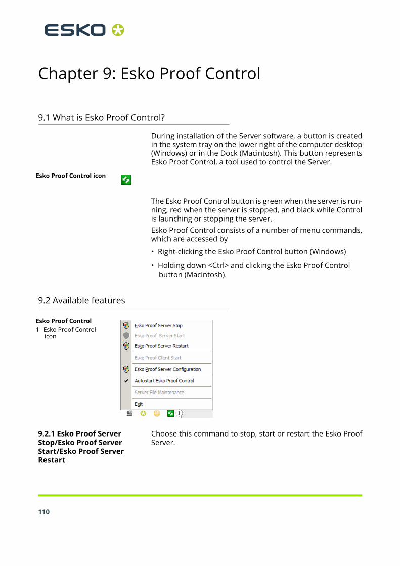
Chapter 9: Esko Proof Control
9.1 What is Esko Proof Control?
110
During installation of the Server software, a button is createdin the system tray on the lower right of the computer desktop(Windows) or in the Dock (Macintosh). This button representsEsko Proof Control, a tool used to control the Server.
Esko Proof Control icon
The Esko Proof Control button is green when the server is run-ning, red when the server is stopped, and black while Controlis launching or stopping the server.Esko Proof Control consists of a number of menu commands,which are accessed by
• Right-clicking the Esko Proof Control button (Windows)
• Holding down <Ctrl> and clicking the Esko Proof Control button (Macintosh).
9.2 Available features
Esko Proof Control1 Esko Proof Control
icon
1
9.2.1 Esko Proof Server Stop/Esko Proof Server Start/Esko Proof Server Restart
Choose this command to stop, start or restart the Esko ProofServer.

Esko Proof Control 9
9.2.2 Esko Proof Client Start
Choose this command to start Esko Proof from the systemtray. This command is only available if Client and Server are in-stalled on the same computer.
9.2.3 Esko Proof Server Configuration (Windows only)
The Esko Proof Server runs on Windows as a service. By de-fault, the login rights are defined for the local computer. Thismeans that Esko Proof is not able to communicate with folderslocated in a network environment. This may present prob-lems, for example, if you wish to print jobs via a hotfolder. Inthis case, you need to assign network access rights for theEsko Proof Server.
See also:
“Printing via a hotfolder” on page 101
9.2.4 Autostart Esko Proof Control (Windows)/Open at Login (Macintosh)
By default, Esko Proof Control will be started automaticallywhenever you turn on your computer. The command has acheck mark next to it.Choose this command to remove the check mark if you do notwant Esko Proof Control to be started automatically. In thiscase, you can start the tool manually when required, as fol-lows:
• go to Start > All Programs > Esko > Esko Proof > Esko Proof Control (Windows)
• click the Esko Proof Control icon in the dock (Macintosh)
9.2.5 Server File Maintenance
You must stop the Esko Proof Server to activate Server FileMaintenance.With the Server File Maintenance option, you can redefine thepath to important server folders and select a new location formedia profiles, reference profiles, the JobFolder, output files,and temporary files. As an example, you can move media pro-files to a different partition to free up disk space on the C drive.
9.2.6 Exit (Windows)/Quit (Macintosh)
Choose this command to exit Esko Proof Control. You can thenrestart it manually.
See also:
“Autostart Esko Proof Control (Windows)/Open at Login (Macintosh)” on page 111
111

Chapter 10: Troubleshooting
112
If you encounter problems while working with Esko Proof, tryperforming the suggested solutions. If the problem still per-sists, please contact Esko Support.
10.1 Server/Logging on
I cannot see the Server user interface? How can I log in?
Cause: The Server runs as a service, so it has no user interface. All actions are initiated in the Client software.
Remedy: To start the Client, click the program icon on the desktop (Windows) or in the Dock (Macintosh).
I am working with Windows and the Server does not accept any connection from a Client. What can I do in this case?
Cause: A firewall might be set up on your version of Windows.
Remedy: Unlock ports 50005 - 50025. Please refer to Windows help for further information.
Although I am able to log on to Esko Proof successfully, I cannot see any users, workflows or output devices.
Cause: A firewall might be set up on your version of Windows.
Remedy: Unlock ports 50005 - 50025. Please refer to Windows help for further information.

Troubleshooting 10
When I try and log on, I get the error message “The user 'admin' is unknown. Please make sure that you type in the correct name.”
Cause: The file usr_0000.xml may be missing.Remedy: In the Tickets folder, search for the file
usr_0000.xml.
If you find the usr_0000.xml file, cut and paste it to a destination outside the Tickets folder. Then restart the Server. A new usr_0000.xml file is automatically created.
If the usr_0000.xml file is missing but you find a usr.0000.bak file, restart the Server. During Server restart, a new usr_0000.xml is automatically created.
If you cannot find either a usr.0000.xml or a usr.0000.bak file, contact Esko Support for a new usr.0000.xml file. When you receive the file, copy it to the Tickets folder.
The start screen opens briefly and then closes. Why is this?
Cause: This behavior occurs because Microsoft Windows uses the Data Execution Prevention (DEP) feature to help prevent damage from viruses and from other security threats.
Remedy: Deactivate Data Execution Prevention for Esko Proof as follows:
1 Right-click on Computer and choose Properties from the context menu.2 Click Advanced system settings.3 In the System Properties dialog, select the Advanced tab.4 Click the Settings button for performance.5 In the Performance Options dialog, select the Data Execution Prevention tab.6 Select the radio button “Turn on DEP for all programs and services except those I select:”. Then click Add and navigate to the Client folder.
113

114
7 Select all the application files with the extension *.exe and add them to the list of programs which are not affected by DEP.8 Then add all the application files located in the Server folder in the same way.
See also:
“Logging on to an Esko Proof Server” on page 10
10.2 Printing
Invalid page height
Cause: The information from the bounding box is not taken into account.
Remedy: In System Manager, highlight the workflow. On the Input tab, open the File formats pane and select “Calculate page size”.
Command Error
Cause: Some printers can be used with two different types of ink (e.g. Ultrachrome Photo and Matte). The error message occurs if the type of ink selected in Esko Proof does not match the type of ink inserted in the printer.
Remedy: Make sure that you select the right type of ink for the output device. The black ink cartridge lets you identify the type of ink being used. Make the correct ink type setting on the Media pane of the Device tab.
I am unable to load any jobs. Why?
Cause: You may not have enough valid printer/output licenses.
Remedy: Check whether you have enough licenses in the License Manager:

Troubleshooting 10
If you do, but are unable to load jobs anyway, proceed as follows:
1 In System Manager, disconnect all workflows from all output devices.2 Highlight the linearization device.3 On the Device tab, open the Information pane and choose “Select device type” from the drop-down list.4 Save the settings for the linearization device.5 Connect one workflow to one output device.6 In Job Explorer, try and load a job.Cause: The amount of used disk space is exceeded.Remedy: Ensure that the amount of used disk space
does not exceed 95%. If necessary, free up additional space on the hard disk.
During job processing a bco file is created in the default Output folder. You can reduce the amount of hard disk space required by Esko Proof during job processing by redefining this path, e.g. to a folder on a different drive, as follows:
1 Stop the Server.2 Open the Tickets folder.3 In a text editor, open the file sys_0000.xml4 Search for the line beginning <Print type= and type in a new path.
I have set up a hotfolder in a network, but submitted jobs do not appear in the job list. What is the problem?
Cause: The Esko Proof Server runs on Windows as a service. By default, the login rights are defined for the local computer. This means that Esko Proof is not able to communicate with folders located in a network environment. This may present problems, for example, if you wish to print jobs via a hotfolder.
Remedy: You need to assign network access rights for the Esko Proof Server.
115

116
1 Right-click the Esko Proof Control icon in the system tray and select “Esko Proof Server Configuration” (Windows only).2 In the Services window that opens, right-click Esko Proof Server and select “Properties”.
Services window

Troubleshooting 10
3 In the Esko Proof Server Properties window that opens, select “This account” and enter the credentials of the user with administrative rights printing via the hotfolder.
Windows login rights
See also:
“Esko Proof Server Configuration (Windows only)” on page 111
“Printing via a hotfolder” on page 101
117

10.3 Media profiles
118
I have created a media profile, but why is it not available for selection in Esko Proof?
Cause: The profile may not be saved under a unique name, making it difficult to recognize in the list of available media profiles.
Remedy: It is recommended that you create a base linearization for a unique media name, so that the profile can be more easily found in Esko Proof.
Cause: The epl file is not saved in the Profiles folder.Remedy: Make sure that the epl file and the ICC profile
are saved in the Media Profiles folder.
10.4 USB devices
When I connect my USB measuring device to the computer, I am requested to install the device driver. Should the device driver not be detected automatically?
Cause: Occasionally the device driver may not be detected automatically when you connect the USB device to the computer.
Remedy: The device drivers are installed automatically with the software.
If the wizard prompts you to install the device driver from the DVD, browse to the USB Measurement Devices folder and select the appropriate device driver.
Why is my USB device not being detected?
Cause: The device driver may not be installed.Remedy: Install the device driver as follows:

Troubleshooting 10
1 Right-click on Computer and choose Properties from the context menu.2 Click Advanced system settings.3 In the System Properties dialog, select the Hardware tab.4 On the Hardware tab, click Device Manager.5 Search for Universal Serial Bus controllers.6 Expand the list and search for the device that is not detected. Non-detected devices appear with a question mark next to them.7 Right-click on the device entry and choose Update Driver from the context menu.8 Download and install the current driver by selecting the recommended setting.
Alternatively, a list of manufacturer home pages is provided with Esko Proof in the Tools and Other folder.
10.5 Support
If you run into difficulties while working with Esko Proof andyou cannot find the solution in this manual, please contactEsko for technical assistance. You will find the contact details for your region on the supportweb page: click this link or go to http://esko.com/support andclick Contact Support.Please make sure to provide the following information whencontacting Esko:
• Version name and release number of your software
• License information
• Printer model
• Operating system with version numberAny additional hardware and software you may have installed(e.g. ISDN boards, virus scanners, etc.)
119
Chapter 11: Uninstalling
120
This section describes how to uninstall Esko Proof and the me-dia profiles. The dialogs may vary slightly, depending on theapplication you are uninstalling.
Uninstalling Esko Proof also automatically uninstalls Esko Ver-ification (if it is installed).
TO UNINSTALL VIA THE WINDOWS CONTROL PANEL
Use the procedure below to uninstall Esko Proof or media pro-files.1 Open the Control Panel.2 Click Uninstall a program.3 In the list of installed programs, right-click the application you want to uninstall and select Uninstall.4 Follow the procedure of your operating system for removing programs.
Make sure to restart your computer before reinstalling.
TO UNINSTALL VIA WINDOWS SETUP PROGRAM
Use the procedure below to uninstall Esko Proof, media pro-files or Unidriver.1 Insert the software DVD into the DVD-ROM drive.
The start screen starts automatically. If the start screen does not appear, double-click the Start.exe file located on the DVD.
2 Click Install Esko Proof to start the installation wizard.
3 In the Welcome screen of the installation wizard, click Remove and follow the on-screen instructions to complete the uninstallation.
Make sure to restart your computer before reinstalling.
TO UNINSTALL VIA MACINTOSH SETUP PROGRAM
Use the procedure below to uninstall Esko Proof or media pro-files.1 Insert the software DVD into the DVD-ROM drive.

Uninstalling 11
2 Double-click the program icon to start the setup procedure and follow the on-screen instructions until you come to the Installation Type screen.
3 On the Installation Type screen, select “Uninstall” from the drop-down list and click the Uninstall button.4 Follow the on-screen instructions to complete the procedure.
Make sure to restart your computer before reinstalling.
121

Glossary
122
This glossary gives a brief explanation of the terms used in thismanual.
Base linearization
Printers do not work in a linear fashion and achieve their max-imum color density at approximately 50%. As a result, testcharts for creating profiles do not have differentiated colorpatches for the upper chromatic values.A base linearization makes the density curve of the printer lin-ear (input value = output value), thus creating an importantbasis for ICC-compatible color management.C
Color temperature of 6,774 Kelvin, which corresponds to day-light.CIE 94
A tolerancing system utilizing three-dimensional ellipsoids ascontainers for color acceptance. CIE 94 is similar to CMC butlacks some of the hue lightness adjustments. CIE 94 colorshave 95% agreement with color differences as our eyes seethem. CIE 94 is used predominantly in the paint and coatingsindustry.CIELAB
A color model based on the model proposed by the Commis-sion Internationale de l’Eclairage (CIE) in 1931 as an interna-tional standard for color measurement. In 1976, this modelwas refined and named CIELAB. L*a*b* color is designed to bedevice-independent and perceptually uniform. L*a*b* colorconsists of a luminance or lightness component (L*) and twochromatic components: the a* component (from green to red)and the b* component (from blue to yellow).CIELCH
A color space similar to CIELAB, which uses cylindrical coordi-nates of lightness, chroma, and hue angle instead of rectangu-lar coordinates.
Glossary G
CMC
A tolerancing system based on CIELCH. It portrays colors asthree-dimensional ellipsoids and represents colors as they areinterpreted by the human eye. CMC colors have 95% agree-ment with color differences as our eyes see them. CMC is usedpredominantly in the textile industry.Compensation of plate characteristic
A function to linearize a non-linear plate characteristic of one-bit files before they are processed in color management. Thisenables the use of media profiles that are based on linear con-tinuous-tone data.To produce a color-accurate proof from non-linear plate char-acteristics calculated into the one-bit files requires a mediaprofile that is based on the IT8 target using the non-linear one-bit files.Delta E
The mathematically calculated distance in the CIE L*a*b* col-or space between two colors. Delta E is used to check total col-or tolerances in a color-management environment.Delta H
The difference in hue. In a color wheel, hue is defined by theangle between two colors.Delta H
See also Hue
123
Delta T
124
The ISO 12647 norm defines delta T purely as a colorimetricvalue for dot gain — unlike the dot gain commonly referred toin printing houses, which is composed of an optical part (lighttrapping) and a mechanical part (dot spread).Dot gain can only be measured using pure primary colors. If,for example, the full-tone color Cyan is output on an inkjetprinter to simulate offset printing, it will not have the CMYKvalue 100, 0, 0, 0, but will also contain a percentage of magen-ta, yellow and black.
Device link profile
A Device Link profile represents a fixed combination of printerand media type.Gamma
The ratio of the contrast range between original and repro-duction. A gamma value of 1 means that the original and copyproof have the same contrast range.Halftone screening
A process by which a continuous-tone image is converted intoa pattern of regularly spaced dots. The individual dots all havethe same density, but vary in size. The color tone of a printedarea is dictated by the size of the printed dots — the larger thedots, the darker the reproduced color tone.Hue
The dominant wavelength of a color. A color system, or model,measures color by hue, saturation and luminance. The hue isthe predominant color, such as yellow or green, the saturationis the color intensity, and the luminance is the brightness.L*a*b*
See CIELABPage
Image on a nesting. Pages can be in any supported file format.For multi-page documents, each page is nested and pre-viewed.
Glossary G
Quantity of color
A process to define the maximum quantity of ink for each inkchannel and so prevent colors from becoming oversaturatedand “bleeding”.RGB
The additive color system used in digital cameras and comput-er monitors where red, green, and blue light is captured sepa-rately and then combined to create a full color image.Tone value
The amount that an ink halftone dot expands when applied tothe surface of a media, causing darker tones or stronger col-ors. This is usually a factor of the type of press and the absor-bency of the media.For example, screen printing increases density by about 15%,so an image with a 50% black fill would appear as approxi-mately 65% black after printing.Sheet
Sheet refers to the defined output size of a nesting. It can beequal to, or smaller or larger than the media size defined forthe output device. If the defined sheet size exceeds the maxi-mum media size supported by the selected printer, the nest-ing can be output as a tiling.System workflow
A system workflow consists of a user, workflow and output de-vice. It refers to all work processes from file input by a user tofile output on a specified printer.Total ink limit
The total ink limit describes the point at which a printer attainsits maximum color density.125

126
Most inkjet printers do not increase color density in a linearfashion. In many cases, the maximum color density isachieved at approximately 50%, as illustrated in the graph.
White point
Total ink limit
In printing, the white point describes the whiteness of the pa-per. In colorimetric terms, the white point is defined as thechromaticity of a white light source or other emissive object.The white point may be expressed in terms of correlated colortemperature or chromaticity coordinates.
XYZ
A device-independent color model developed by CIE (Commis-sion Internationale de l'Eclairage), in which RGB values aremathematically transformed into a system that uses x, y and zas coordinates. While x and z values have no specific percep-tual correlation, the y value represents brightness (lumi-nance).
Glossary G
127

Index
A
Alignmentjob 48nesting job 77, 87snap to 83
B
Backups 67
environment 70system configuration 68
Balancing, workload 38
C
Copies, number of 57
Creatingnestings 106output devices 22system workflows 13users 19, 34workflow templates 28, 21, 34
Crop marks 55
position 56
D
Deleting temporary files 35
E
Environmentbacking up 70restoring 71
128
EPL, selecting 61
EPS job detection 44
Esko Proof Control 110
Autostart 111
F
Final run characteristics 58
First printable dot 58
Flipping job 46, 79
Fonts, missing 40
Footer 52
G
Guides 83
H
Hard disk space, available 33
Hotfolder 37
setting up 100
I
Inverting job 57

Index I
J
Jobalignment on nesting 77, 83, 87, 48flipping 46, 79inverting 57margins 48priority 86rotating 46, 79scaling 47, 46
Job Explorercontext menus 85menus 74overview 24property inspector 89toolbars 86
Job list, displayed information 25
Job status 33
Job ticket 52
Jobscopying 80moving 81
L
Language of user interface, changing 29, 80
Layoutnesting 48step & repeat 50
Linearization device 13
Load balancing 38
Logging on 10, 29, 74
Logo, job ticket 54
M
Measurement system, changing 30, 80
Media feed 62
Media length correction 62
Media profiles 8
troubleshooting 117
Media size 62
Monitor profiles 30, 80
N
Nestings 104
automatic 106editing 107job settings 75, 81layout aids 84, 48manual 106overlapping jobs 76, 87
Noise smoothing 58
O
Output deviceconnecting 60, 22setting up 60
Overprinting 43
P
PDFpage size 41
Preview 76
settings 35, 82, 85zoom 82
Print engine 45
Print speed, influencing 36
Printer calibration 63
Printer features, special 63
Printingcopies 57directly from Esko Proof 98separated files 57troubleshooting 114via a hotfolder 100, 39
129

Programfolders 7overview 24
R
Renaming jobs 86
Resources, available hard disk space 33
RIP resolution 36
Rotating job 46, 79
S
Scaling job 47
Separated file output 57
Server configuration 111
Server, logging on to 10
Setting up 13
Settingsnesting 48, 75, 81, 84Step & repeat 50
Sheet size 46
Step & repeatinput resolution 44layout settings 50settings 50
Support 119
System configurationbacking up 68restoring 69
System Managermenus 28overview 25property inspector 33toolbar 33
System requirements 7
System workflows 12
default 12setting online 23, 13
130
T
Temporary files, deleting 35
ToolbarJob Explorer 86
Troubleshootinglicensing 10, 112media profiles 117printing 114server 112USB devices 118
U
Uninstalling 120
USB devices, troubleshooting 118
Usercreating 19logging on 29, 74password 34settings 34
V
Virtual printer 39
W
Workflowcreating 21high priority 36settings 34
Workflow template, creating 28
Working color space 43
Workload, distributing 38
Z
Zoom 82