Embed Size (px)
Citation preview
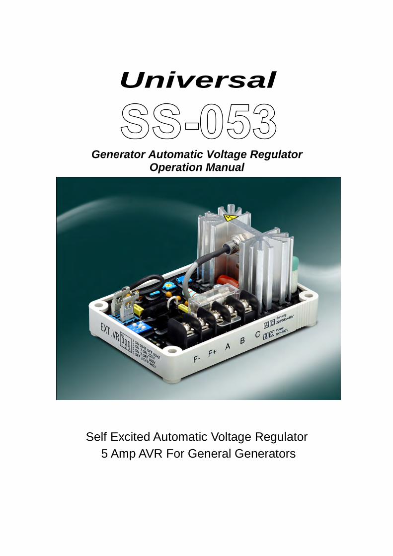
Generator Automatic Voltage Regulator Operation Manual
Self Excited Automatic Voltage Regulator 5 Amp AVR For General Generators
Universal
______________________________________________________________________________________
2 SS053
1. INTRODUCTIONSensing Input
Voltage 220 / 380 / 440 VAC, 1 phase2 wireDIP switch selectable
Frequency 50 /60 Hz, DIP switch selectable
Power Inpu tVoltage 100 ~ 300 VAC, 1 phase 2 wire
OutputVoltage Max. 63 VDC @ 220 VAC input
Max. 90 VDC @ 240 VAC inputCurrent Continuous 5A
Intermittent 7A for 10 secResistance Min. 15 ohm Max. 100 ohm
Voltage Regulation< ± 0.5% ( with 4% engine governing )
Voltage Build-upResidual voltage at AVR terminal > 5 VAC
Thermal Drift0.03% per ?C change in AVR ambient
External Volts Adjustment7% with 1K ohm 1 watt trimmer
EMI SuppressionInternal electromagnetic interference filtering
Unit Power DissipationMax. 8 watt
Under Frequency Protection (Factory Setting)60 Hz system presets knee point at 55 Hz50 Hz system presets knee point at 45 Hz
Soft Start Ramp Time3 sec.
Dimensions101mm L * 69mm W * 47.5mm H
Weight183g ± 2%
2. WIRING
1. When the rated phase voltage of the generator is220VAC, the input terminals B, C and sensingterminals A, C are the same (as infigure 3. factory setting). or connectindependent. (as show as figure 2).
2. But when the voltage of the generator is 380V,480V, the power input terminals B, C and sensingterminals A, C are connected separately(as show in Figure 4 or figure 5). Power inputsB and C must never go over 300 VAC.
3. F+, F- terminals connect to the generator field. ( Jand K )
4.- For use with independet power winding see Fig 10
EXT.VR is rated at (1K Ohm 1W) Keep terminalsshorted when the external pot is not used.
P.S. : A, B, C, F+, F- usage AWG 16 1.25 mmwire gauge are
2
85oC above 600V.
The EXT.VR connection wires must be insulated.
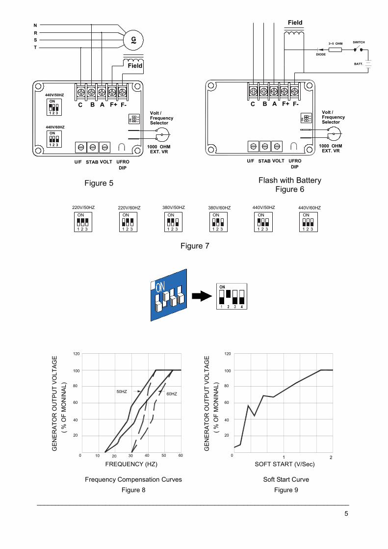
3. ADJUSTMENTSSet voltage setting for 220V / 380V / 440V andfrequency setting for 50/60HZ is show in figure7.double check the voltage/frequency settingbefore start the generator.
CAUTION :
THE GENERATOR OR AVR MAY BE DAMAGEDIF THE VOLTAGE / FREQUENCY SELECTORSETTING IS SET WRONG.
In a standard AVR, when the generator has an unbalanced load, the NEUTRAL conducts the current from this unbalance load, andthe voltage from the N to the 3 phases constantly changes the sensing reference input voltage tothe AVR making it hard to have a constant output voltage on the generator.
This model AVR corrects this problem by sensingdirectly from the output of the generator beingbeing it 220, 380, or 490 volts.
or internel Auxiliary Winding
______________________________________________________________________________________
SS053 3
UFRO DIP:Close - refer to solid curve in Figure 8.Open - refer to dotted curve in Figure 8.
1 Before starting the generator, set the voltage and stability, adjustment full CCW and with the engine runs, set the voltage adjustment CW to the voltage required. (If you are using an external remote pot, set this pot to its center position before adjusting the pot on the AVR)
2. Adjust the "STAB" move CW slowly until the voltage becomes unstable and then back it up. Whenunder-adjusted, the AVR reaction time is slow. By using an old-fashioned needle voltmeter, adjusting the "stability" is easier when you are looking for a stable needle when changing load.
4. FIELD FLASHINGWhen the regulator is operated for the first timethe polarity of residual magnetism may bereversed or too small to achieve the necessary
build-up voltage for the regulator. If reversing the fieldwires does not induce build-up, and theresidual voltage is less than then 5 Vac, stopthe engine and proceed with the next steps
1. With the engine at rest and the regulator's field wires disconnected, apply the DC voltage from a 12 volt battery to the fields with the Positive to F+ and Negative to F-, using a current-limiting resistor from 3 to 5 ohms 20 watt. (The set battery is OK.)
2. Flash allowing 3 seconds before removing the DC volts.
3. Disconnect the AVR (wires 3 and 4)start the generator and remeasure the “residual” voltage, if thisvoltage is now greater than 5 Vac, reconnect the voltage regulator.But if less than 5 Vac repeat thefield flashing procedure.
4. If repeating steps a and b does not result in generator voltage build-up, but residual is greater than 5 Vac, replace the voltage regulator.
5. TROUBLE SHOOTING
SYMPTOM CAUSE CORRECTIONEngine speed is too low. refer to the Generator Manual. Residual voltage is too low. refer to the section introduction of
excite. B,C,F+,F- wires are not connected well. refer to Figure 2 ~ Figure 5.
Voltage does not build up
Defective Generator. refer to the Generator Manual. The input wiring of A,B,C are not correct. refer to Figure 2 ~ Figure 5. Check the external potentiometer. Check wiring and potentiometer. Under frequency. refer to the Generator Manual. The exciter does not match the AVR. refer to the Generator Manual.
Out voltage low
The voltage / frequency selector setting is not correct.
refer to Figure 7.
Fuse blown The exciter flash is too large or wiring doesn’t connect well.
refer to the Generator Manual. refer to Figure 2 ~ Figure 5.
A,C terminals are not connect or wiring
The voltage / frequency selector setting
incorrect. refer to Figure 2 ~ Figure 5. Out voltage high
is not correct. refer to Figure 7.
Out voltage instable Stability Adjustment doesn’t adjust well. refer to the section introduction of Adjustment.
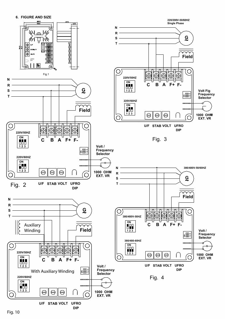
6. FIGURE AND SIZE
ON
12
3
3
ON
1 2
220V/60HZ
220V/50HZ
NRST
G~
Field
C B A F+ F-
1 32
ON
U/F STAB VOLT UFRODIP
1000 OHMEXT. VR
FrequencySelector
Volt /
Field
~G
380/480-60HZ
380/480V-50HZ
380/480V-50/60HZ
STABU/F
321
ON
VOLT
C321
ONB F-F+A
ON
R
TS
N
31
2
UFRODIP
1000 OHMEXT. VR
FrequencySelector
Volt /
Field
220V/60HZ
220V/50HZ
220/208V-50/60HZSingle Phase
21 3
ON
21 3
ON
STABU/F VOLT
BC F-F+A
R
TS
N
3
ON
12
~G
UFRODIP
1000 OHMEXT. VR
FrequencySelector
Volt Fig
Fig.1
Fig. 2
ON
12
3
3
ON
1 2
220V/60HZ
220V/50HZ
NRST
G~
Field
C B A F+ F-
1 32
ON
U/F STAB VOLT UFRODIP
1000 OHMEXT. VR
FrequencySelector
Volt /
Fig. 3
Fig. 4
UFRODIP
AuxiliaryWinding
With Auxiliary Winding
Fig. 10
______________________________________________________________________________________
5
2 31
ON220V/60HZ
21 3
220V/50HZ
ON
380V/50HZ 380V/60HZ
31 2
ON
31 2
ON ON
440V/50HZ 440V/60HZON
1 321 2 3
Figure 5 Flash with BatteryFigure 6
Figure 7
Frequency Compensation CurvesFigure 8
Soft Start CurveFigure 9
GEN
ER
ATO
RO
UTP
UT
VO
LTA G
E
GEN
ER
ATO
RO
UTP
UT
VO
LTAG
E
SOFT START (V/Sec)10
FREQUENCY (HZ)10 20 4030 00605 2
60HZ
(%O
FM
ON
INA
L) 80
20
40
60
50HZ
120
100
(%O
FM
ON
INA
L) 80
20
40
60
120
100
32
1
Field
ON440V/60HZ
440V/50HZON
1
1
STABU/F
32
VOLT
C B32
A F+ F-
ON
R
TS
N
~G
UFRODIP
1000 OHMEXT. VR
FrequencySelector
Volt /
ON
Field
STABU/F VOLT
C A F+ F-B
1000 OHM
32
1
DIODE
3~5 OHM SWITCH
BATT.
UFRODIP
EXT. VR
FrequencySelector
Volt /