Embed Size (px)
Citation preview
Ministry of Civil Aviation EAC 139-10
Egyptian Civil Aviation Authority
Issue 5, Rev. 1 Dated March, 2013 Page 1
EAC
No. 139-10
Ministry of Civil Aviation EAC 139-10 Egyptian Civil Aviation Authority
Page 2 Dated March, 2013 Issue 5, Rev. 1
TABLE OF CONTENTS
TITLE TITLE
1Chapter Taxiways
2Chapter Holding bays and other bypasses
3Chapter Aprons
4Chapter Segregation of traffic on the movement area
1Appendix Fillet design
2Appendix Jet blast fence consideration
3Appendix Aero plane classification by code number and letter
4Appendix Taxiway deviation study
5Appendix Design, Location And Number Of Rapid Exit Taxiways
Ministry of Civil Aviation EAC 139-10
Egyptian Civil Aviation Authority
Issue 5, Rev. 1 Dated March, 2013 Page 3
CHAPTER 1
Taxiways
1.1 Taxiway Systems Functional requirements 1.1.1 Maximum capacity and efficiency of an aerodrome are realized only by obtaining the
proper balance between the need for runways, passenger and cargo terminals, and aircraft storage and servicing areas. These separate and distinct aerodrome functional elements are linked by the taxiway system. The components of the taxiway system therefore serve as the transitional media between the aerodrome functions and are necessary to develop optimum aerodrome utilization.
1.1.2 The taxiway system should be designed to minimize restriction to aircraft movement to and from the runways and apron areas. A properly designed system should be capable of maintaining a smooth, continuous flow of aircraft ground traffic at the maximum practical speed with a minimum of points requiring acceleration or deceleration. This requirement ensures that the taxiway system will operate at the highest level of safety and efficiency.
1.1.3 For any given aerodrome the taxiway system should be able to accommodate (without significant delay) the practical acceptance level of demand for aircraft arrivals and departures on the runway system. At low levels of runway utilization the taxiway system can accomplish this with a minimum number of components. However, as the runway acceptance rate increases, the taxiway system capacity must be sufficiently expanded to avoid becoming the limiting aerodrome capacity factor. In the extreme case of runway capacity saturation, when aircraft are arriving and departing at the minimum separation distances, the taxiway system should allow aircraft to exit the runway as soon as practical after landing and to enter the runway just before take-off. This enables aircraft movements on the runway to be maintained at the minimum separation distance.
Planning principles 1.1.4 Runways and taxiways are the least flexible of the aerodrome elements and must
therefore be considered first when planning aerodrome development. Forecasts of future activity should identify changes in the rate of aircraft movements, the nature of the traffic and the type of aircraft and any other factors affecting the layout and dimensioning of the runway and taxiway systems. Care should be taken not to place so much attention on present needs of the system that later phases of development that have equal or greater importance are neglected. For example, if an aerodrome is forecast to serve a higher category of aircraft type in the future, the current taxiway system should be designed to accommodate the greatest separation distances that ultimately will be required (see Table 1-1).
1.1.5 In planning the general layout of the taxiway system, the following principles should be considered:
(a) Taxiway routes should connect the various aerodrome elements by the shortest distances, thus minimizing both taxiing time and cost;
(b) Taxiway routes should be as simple as possible to avoid pilot confusion and the need for complicated instructions;
(c) Straight runs of pavement should be used wherever possible. Where changes in direction are necessary, curves of adequate radii, as well as fillets or extra taxiway width, should be provided to permit taxiing at the maximum practical speed (see Section 1.4 and Appendix 1);
(d) Taxiway crossings of runways and other taxiways should be avoided whenever possible in the interests of safety and to reduce the potential for significant taxiing delays;
(e) Taxiway routings should have as many one-way segments as possible to minimize aircraft conflicts and delay. Taxiway segment flows should be analysed for each configuration under which runway(s) will be used;
Ministry of Civil Aviation EAC 139-10 Egyptian Civil Aviation Authority
Page 4 Dated March, 2013 Issue 5, Rev. 1
(f) the taxiway system should be planned to maximize the useful life of each component so that future phases of development incorporate sections from the current system; and
(g) ultimately, a taxiway system will perform only as well as its least adequate component. Therefore, potential bottlenecks should be identified and eliminated in the planning phase.
1.1.6 Other considerations of importance when planning a taxiway system include the following:
(a) Taxiway routes should avoid areas where the public could have easy access to the aircraft. Security of taxiing aircraft from sabotage or armed aggression should be of primary importance in areas where this is of particular concern;
(b) Taxiway layouts should be planned to avoid inter- ference with navigation aids by taxiing aircraft or ground vehicles using the taxiway;
(c) All sections of the taxiway system should be visible from the aerodrome control tower. Remote cameras can be used to monitor sections of taxiways shadowed by terminal buildings or other aerodrome structures if such areas cannot be practically avoided;
(d) The effects of jet blast on areas adjacent to the taxiways should be mitigated by stabilizing loose soils and erecting blast fences where necessary to protect people or structures (see Appendix 2); and
(e) The location of taxiways may also be influenced by ILS installations due to interferences to ILS signals by a taxiing or stopped aircraft. Information on critical and sensitive areas surrounding ILS installations is contained in Annex 10, Volume I, Attachment C to Part 1.
1.1.7 Entrance and exit taxiways serving a specific runway should be of sufficient number to accommodate the current demand peaks for take-offs and landings. Additional entrances and exits should be designed and developed to stay ahead of expected growth in runway utilization. The following principles apply to the planning of these taxiway system components:
(a) The function of exit taxiways is to minimize runway occupancy time of landing
aircraft. In theory, exit taxiways can be located to best serve each type of aircraft expected to use the runway. In practice, the optimum number and spacing are determined by grouping the aircraft into a limited number of classes based upon landing speed and deceleration after touchdown;
Ministry of Civil Aviation EAC 139-10
Egyptian Civil Aviation Authority
Issue 5, Rev. 1 Dated March, 2013 Page 5
Ministry of Civil Aviation EAC 139-10 Egyptian Civil Aviation Authority
Page 6 Dated March, 2013 Issue 5, Rev. 1
(b) The exit taxiway should allow an aircraft to move off the runway without restriction
to a point clear of the runway, thus allowing another operation to take place on the runway as soon as possible;
(c) An exit taxiway can be either at a right angle to the runway or at an acute angle. The former type requires an aircraft to decelerate to a very low speed before turning off the runway, whereas the latter type allows aircraft to exit the runway at higher speeds, thus reducing the time required on the runway and increasing the runway capacity (details about the location and geometry of the acute angle type (called rapid exit taxiway) are presented in Section 1.3); and
(d) A single runway entrance at each end of the runway is generally sufficient to accommodate the demand for take-offs. However if traffic volume warrants, the use of bypasses, holding bays or multiple runway entrances can be considered (see Chapter 2).
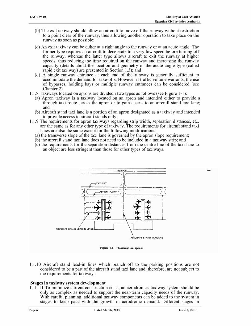
1.1.8 Taxiways located on aprons are divided i two types as follows (see Figure 1-1): (a) Apron taxiway is a taxiway located on an apron and intended either to provide a
through taxi route across the apron or to gain access to an aircraft stand taxi lane; and
(b) Aircraft stand taxi lane is a portion of an apron designated as a taxiway and intended to provide access to aircraft stands only.
1.1.9 The requirements for apron taxiways regarding strip width, separation distances, etc. are the same as for any other type of taxiway. The requirements for aircraft stand taxi lanes are also the same except for the following modifications:
(a) the transverse slope of the taxi lane is governed by the apron slope requirement; (b) the aircraft stand taxi lane does not need to be included in a taxiway strip; and (c) the requirements for the separation distances from the centre line of the taxi lane to
an object are less stringent than those for other types of taxiways.
1.1.10 Aircraft stand lead-in lines which branch off to the parking positions are not
considered to be a part of the aircraft stand taxi lane and, therefore, are not subject to the requirements for taxiways.
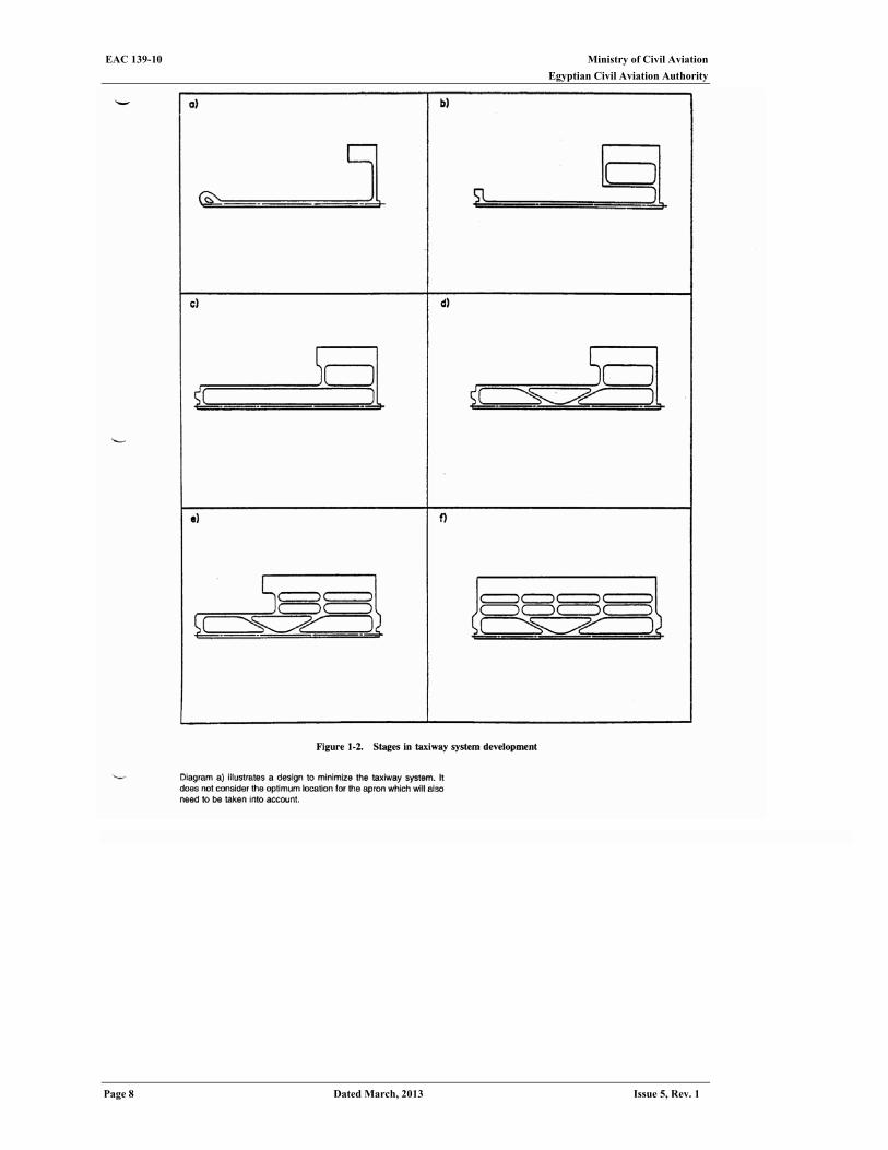
Stages in taxiway system development 1. 1. 11 To minimize current construction costs, an aerodrome's taxiway system should be
only as complex as needed to support the near-term capacity needs of the runway. With careful planning, additional taxiway components can be added to the system in stages to keep pace with the growth in aerodrome demand. Different stages in
Ministry of Civil Aviation EAC 139-10
Egyptian Civil Aviation Authority
Issue 5, Rev. 1 Dated March, 2013 Page 7
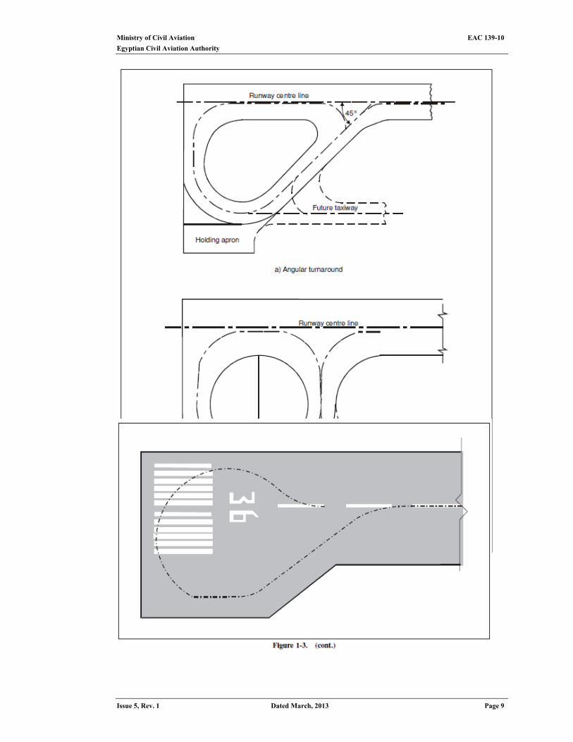
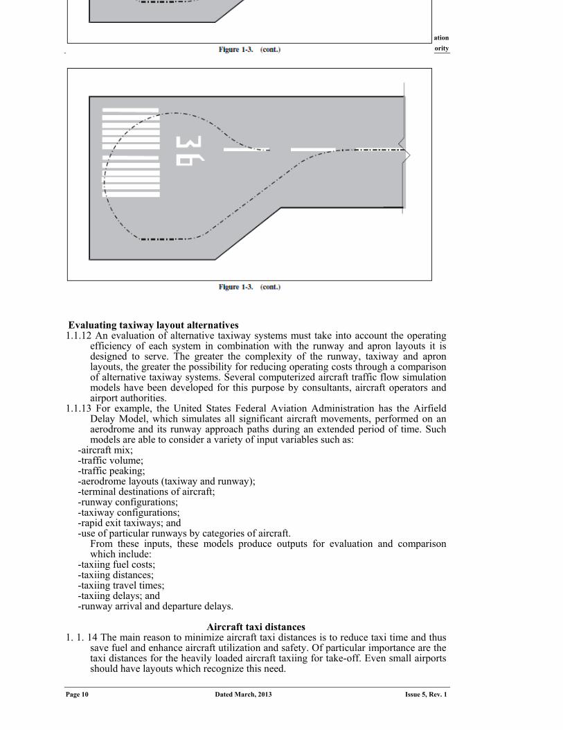
taxiway system development are described in the following paragraphs (see also Figures 1-2 and 1-3):
(a) a minimum aerodrome taxiway system, supporting a low level of runway utilization, can consist of only turnaround pads or taxiway turnarounds at both ends of the runway and a stub taxiway from the runway to the apron;
(b) traffic growth which results in a low to moderate level of runway utilization may be accommodated by building a partial parallel taxiway to connect one or both turnarounds (parallel taxiways provide safety benefits as well as greater efficiency);
(c) as runway utilization increases, a full parallel taxiway can be provided by completing the missing sections of the partial parallel taxiway;
(d) exit taxiways, in addition to the ones at each runway end, can be constructed as runway utilization increases toward saturation;
(e) holding bays and bypass taxiways can be added to further enhance runway capacity. These facilities seldom restrict the attainment of full aerodrome capacity within the existing aerodrome property because land is usually available to permit their construction; and
(f) a dual-parallel taxiway, located outboard of the first parallel taxiway, should be considered when movement in both directions along the taxiway is desirable. With this second taxiway, a one-way flow network can be established for each direction of runway use. The need for the dual-parallel system increases in proportion to the amount of development alongside the taxiway.
For additional information, see the Airport Planning Manual (Doc 9184), Part I - Master Planning.
Ministry of Civil Aviation EAC 139-10 Egyptian Civil Aviation Authority
Page 8 Dated March, 2013 Issue 5, Rev. 1
Ministry of Civil Aviation EAC 139-10
Egyptian Civil Aviation Authority
Issue 5, Rev. 1 Dated March, 2013 Page 9
Ministry of Civil Aviation EAC 139-10 Egyptian Civil Aviation Authority
Page 10 Dated March, 2013 Issue 5, Rev. 1
Evaluating taxiway layout alternatives 1.1.12 An evaluation of alternative taxiway systems must take into account the operating
efficiency of each system in combination with the runway and apron layouts it is designed to serve. The greater the complexity of the runway, taxiway and apron layouts, the greater the possibility for reducing operating costs through a comparison of alternative taxiway systems. Several computerized aircraft traffic flow simulation models have been developed for this purpose by consultants, aircraft operators and airport authorities.
1.1.13 For example, the United States Federal Aviation Administration has the Airfield Delay Model, which simulates all significant aircraft movements, performed on an aerodrome and its runway approach paths during an extended period of time. Such models are able to consider a variety of input variables such as:
-aircraft mix; -traffic volume; -traffic peaking; -aerodrome layouts (taxiway and runway); -terminal destinations of aircraft; -runway configurations; -taxiway configurations; -rapid exit taxiways; and -use of particular runways by categories of aircraft.
From these inputs, these models produce outputs for evaluation and comparison which include:
-taxiing fuel costs; -taxiing distances; -taxiing travel times; -taxiing delays; and -runway arrival and departure delays.
Aircraft taxi distances
1. 1. 14 The main reason to minimize aircraft taxi distances is to reduce taxi time and thus save fuel and enhance aircraft utilization and safety. Of particular importance are the taxi distances for the heavily loaded aircraft taxiing for take-off. Even small airports should have layouts which recognize this need.
Ministry of Civil Aviation EAC 139-10
Egyptian Civil Aviation Authority
Issue 5, Rev. 1 Dated March, 2013 Page 11
1.1.15 At larger airports the issue of aircraft safety has greater significance. Detailed investigations have shown that when a fully laden aircraft is taxied over a distance varying from 3 to 7 km (depending upon the aircraft type, its tire size and type, and the ambient temperature), the tire carcass temperature during takeoff can exceed a critical value of 120oC. Exceeding this critical temperature affects the nylon cord strength and rubber adhesion of the tire and significantly increases the risk of tire failure. The 120oC (250oF) limit used in the industry applies to the take-off run as well as the taxi out. At 1200C the nylon tensile strength is reduced by 30 per cent. Higher temperatures cause permanent deterioration of rubber adhesive properties. Tire failures during take-off are serious because they can result in an aborted take-off with braking being ineffective on those wheels having blown tires.
1.1.16 Taxi distances should therefore be kept to the minimum practicable. In the case of large wide-bodied aircraft, a distance of 5 km is considered to be the acceptable upper limit, and where unfavourable factors exist, such as those which require frequent use of brakes, this limit may have to be reduced.
1.1.17 Every airport master plan, irrespective of the size of the airport development, should recognize the need to minimize taxi distances, especially for departing aircraft, for both economy and safety. The suitable location of rapid exit taxiways can do much to reduce taxi distances for landing aircraft. Further, takeoffs from taxiway intersections and the use of rapid exit taxiways not only reduce taxi distances and runway occupancy time but also increase runway capacity.
1.2 physical characteristics
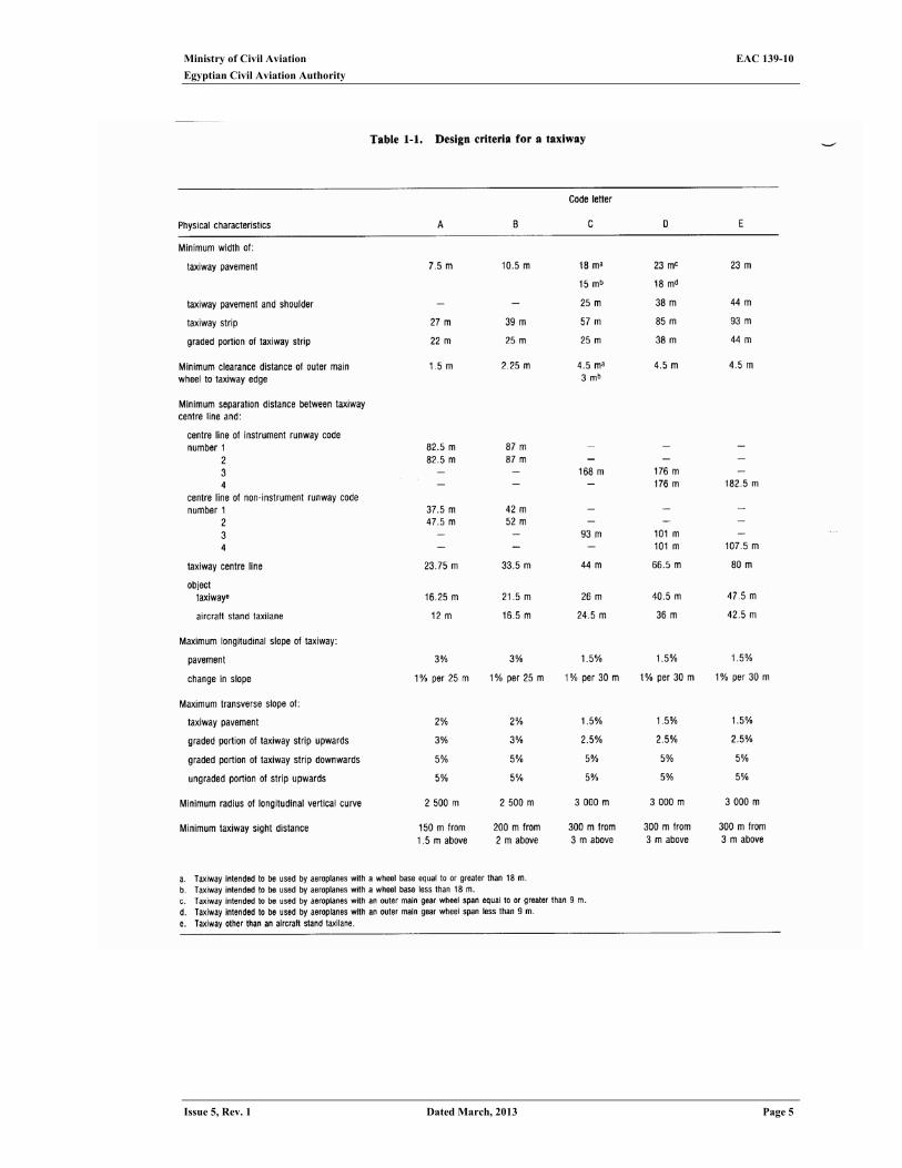
design criteria General 1.2.1 Design criteria for taxiways are less stringent than those for runways since aircraft
speeds on taxiways are much lower than those on runways. Table 1-1 shows the main physical characteristics design criteria recommended for a taxiway in accordance with the specifications in ECAR 139. It should be emphasized that with respect to the clearance distance between the outer main wheel of the aircraft and the edge of the taxiway, it is assumed that the cockpit of the aircraft remains over the taxiway centre line markings.
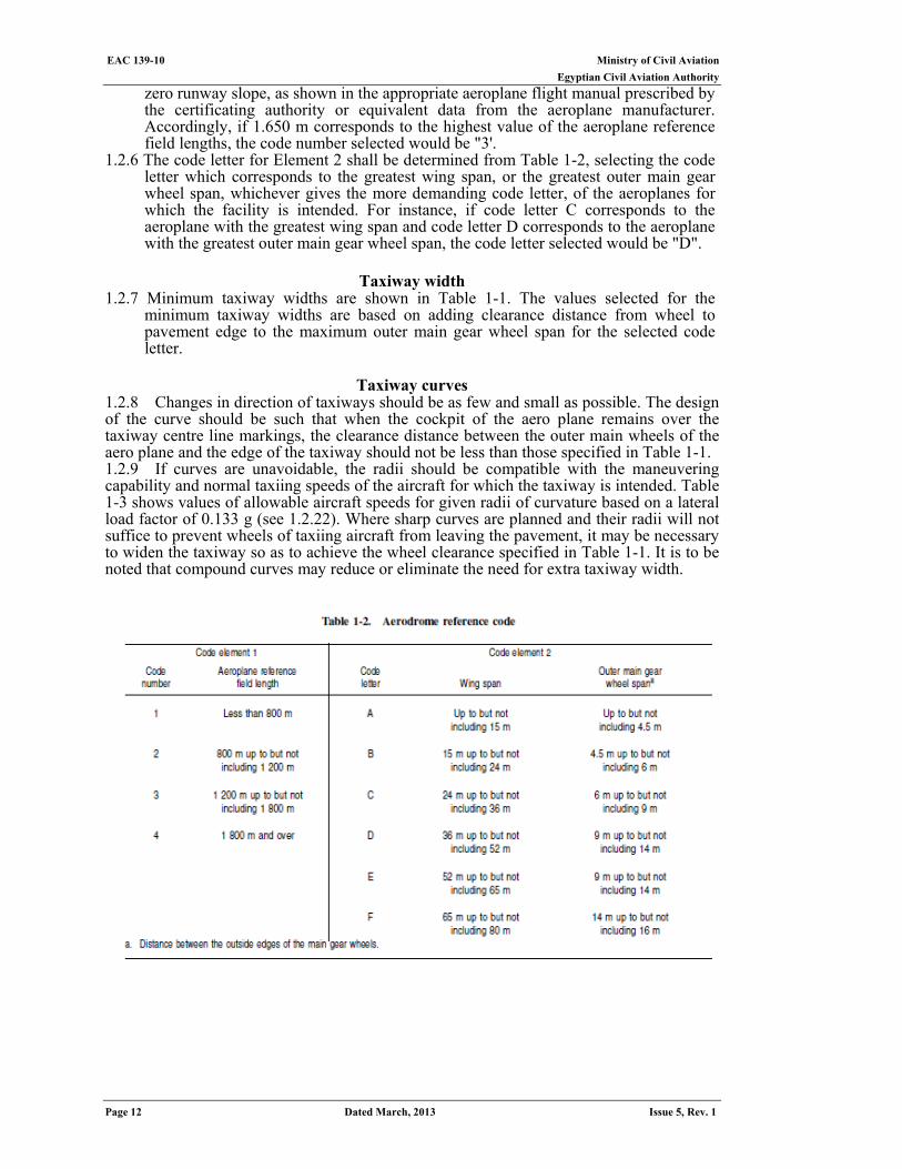
Aerodrome reference code 1.2.2 The intent of the reference code is to provide a simple method for interrelating the
numerous specifications concerning the characteristics of aerodromes so as to provide a series of aerodrome facilities that are suitable for the aeroplanes that are intended to operate at the aerodrome. The code is composed of two elements which are related to the aeroplane performance characteristics and dimensions. Element 1 is a number based on the aeroplane reference field length and Element 2 is a letter based on the aeroplane wing span and outer main gear wheel span.
1.2.3 A particular specification is related to the more appropriate of the two elements of the code or to an appropriate combination of the two code elements. The code letter or number within an element selected for design purposes is related to the critical aeroplane characteristics for which the facility is provided. When applying the relevant specifications in ECAR 139 the aeroplanes which the aerodrome is intended to serve are first identified and then the two elements of the code.
1.2.4 An aerodrome reference code - code number and letter - which is selected for aerodrome planning purposes shall be determined in accordance with the characteristics of the aeroplane for which an aerodrome facility is intended. Further, the aerodrome reference code numbers and letters shall have the meanings assigned to them in Table 1-2. A classification of representative aeroplanes by the code number and code letter is included in Appendix 3.
1.2.5 The code number for Element 1 shall be determined from Table 1-2, selecting the code number corresponding to the highest value of the aeroplane reference field lengths of the aeroplanes for which the runway is intended. The aeroplane reference field length is defined as the minimum field length required for take-off at maximum certificated take-off mass, sea level, standard atmospheric conditions, still air and
Ministry of Civil Aviation EAC 139-10 Egyptian Civil Aviation Authority
Page 12 Dated March, 2013 Issue 5, Rev. 1
zero runway slope, as shown in the appropriate aeroplane flight manual prescribed by the certificating authority or equivalent data from the aeroplane manufacturer. Accordingly, if 1.650 m corresponds to the highest value of the aeroplane reference field lengths, the code number selected would be "3'.
1.2.6 The code letter for Element 2 shall be determined from Table 1-2, selecting the code letter which corresponds to the greatest wing span, or the greatest outer main gear wheel span, whichever gives the more demanding code letter, of the aeroplanes for which the facility is intended. For instance, if code letter C corresponds to the aeroplane with the greatest wing span and code letter D corresponds to the aeroplane with the greatest outer main gear wheel span, the code letter selected would be "D".
Taxiway width
1.2.7 Minimum taxiway widths are shown in Table 1-1. The values selected for the minimum taxiway widths are based on adding clearance distance from wheel to pavement edge to the maximum outer main gear wheel span for the selected code letter.
Taxiway curves
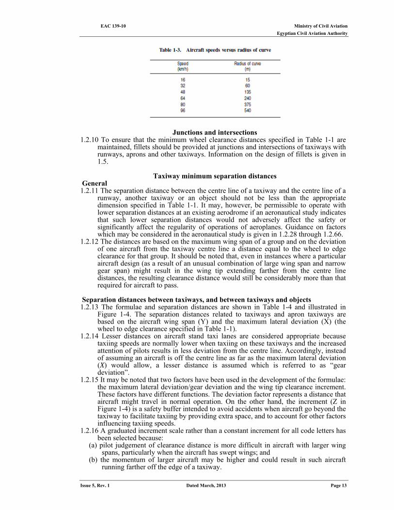
1.2.8 Changes in direction of taxiways should be as few and small as possible. The design of the curve should be such that when the cockpit of the aero plane remains over the taxiway centre line markings, the clearance distance between the outer main wheels of the aero plane and the edge of the taxiway should not be less than those specified in Table 1-1. 1.2.9 If curves are unavoidable, the radii should be compatible with the maneuvering capability and normal taxiing speeds of the aircraft for which the taxiway is intended. Table 1-3 shows values of allowable aircraft speeds for given radii of curvature based on a lateral load factor of 0.133 g (see 1.2.22). Where sharp curves are planned and their radii will not suffice to prevent wheels of taxiing aircraft from leaving the pavement, it may be necessary to widen the taxiway so as to achieve the wheel clearance specified in Table 1-1. It is to be noted that compound curves may reduce or eliminate the need for extra taxiway width.
Ministry of Civil Aviation EAC 139-10 Egyptian Civil Aviation Authority
Issue 5, Rev. 1 Dated March, 2013 Page 13
Junctions and intersections 1.2.10 To ensure that the minimum wheel clearance distances specified in Table 1-1 are
maintained, fillets should be provided at junctions and intersections of taxiways with runways, aprons and other taxiways. Information on the design of fillets is given in 1.5.
Taxiway minimum separation distances
General 1.2.11 The separation distance between the centre line of a taxiway and the centre line of a
runway, another taxiway or an object should not be less than the appropriate dimension specified in Table 1-1. It may, however, be permissible to operate with lower separation distances at an existing aerodrome if an aeronautical study indicates that such lower separation distances would not adversely affect the safety or significantly affect the regularity of operations of aeroplanes. Guidance on factors which may be considered in the aeronautical study is given in 1.2.28 through 1.2.66.
1.2.12 The distances are based on the maximum wing span of a group and on the deviation of one aircraft from the taxiway centre line a distance equal to the wheel to edge clearance for that group. It should be noted that, even in instances where a particular aircraft design (as a result of an unusual combination of large wing span and narrow gear span) might result in the wing tip extending farther from the centre line distances, the resulting clearance distance would still be considerably more than that required for aircraft to pass.
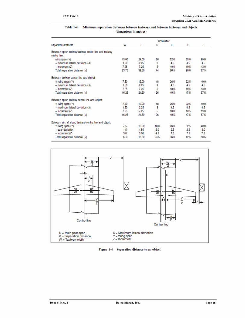
Separation distances between taxiways, and between taxiways and objects 1.2.13 The formulae and separation distances are shown in Table 1-4 and illustrated in
Figure 1-4. The separation distances related to taxiways and apron taxiways are based on the aircraft wing span (Y) and the maximum lateral deviation (X) (the wheel to edge clearance specified in Table 1-1).
1.2.14 Lesser distances on aircraft stand taxi lanes are considered appropriate because taxiing speeds are normally lower when taxiing on these taxiways and the increased attention of pilots results in less deviation from the centre line. Accordingly, instead of assuming an aircraft is off the centre line as far as the maximum lateral deviation (X) would allow, a lesser distance is assumed which is referred to as “gear deviation”.
1.2.15 It may be noted that two factors have been used in the development of the formulae: the maximum lateral deviation/gear deviation and the wing tip clearance increment. These factors have different functions. The deviation factor represents a distance that aircraft might travel in normal operation. On the other hand, the increment (Z in Figure 1-4) is a safety buffer intended to avoid accidents when aircraft go beyond the taxiway to facilitate taxiing by providing extra space, and to account for other factors influencing taxiing speeds.
1.2.16 A graduated increment scale rather than a constant increment for all code letters has been selected because:
(a) pilot judgement of clearance distance is more difficult in aircraft with larger wing spans, particularly when the aircraft has swept wings; and
(b) the momentum of larger aircraft may be higher and could result in such aircraft running farther off the edge of a taxiway.
EAC 139-10 Ministry of Civil Aviation Egyptian Civil Aviation Authority
Page 14 Dated March, 2013 Issue 5, Rev. 1
1.2.17 The increments for the determination of the separation distances between an apron taxiway and an object are the same as those proposed between a taxiway and an object, the reason being that although apron taxiways are associated with aprons, it is thought that their location should not imply a reduction in taxiing speed. Aircraft will normally be moving at slow speeds on an aircraft stand taxi lane and can therefore be expected to remain close to the centre line. Deviations of 1.5, 1.5, 2, 2.5 and 2.5 m have been selected for code letters A to E. The use of a graduated scale for lateral deviation in a stand taxi lane is considered to be appropriate since the ability of a pilot to follow the centre line is decreased in larger aircraft because of the cockpit height.
1.2.18 larger increments have been selected for the separation distances between taxiway/object and apron taxiway/object than for other separation distances. These larger increments are considered necessary because normally objects along such taxiways are fixed objects , thus making the probability of a collision with one of them greater than that of one aircraft running off the taxiway just as another aircraft is passing that point on the parallel taxiway. Also, the fixed object may be a fence or wall which can parallel the taxiway for some distance. Even in the case of a road paralleling a taxiway, vehicles may unknowingly reduce the clearance distance by parking off the road.
Separation distances between taxiways and runways 1.2.19 The separation distances are based on the concept of the wing of an aircraft centred
on a parallel taxiway remaining clear of the strip. The formulae and separation distances are shown in Table 1-5. The separation distance between the centre lines of a runway and a parallel taxiway is based on the accepted principle that the wing tip of an aeroplane taxiing on the parallel taxiway should not penetrate the associated runway strip. However this minimum separation distance may not provide adequate length for the link taxiway connecting the parallel taxiway and the runway to permit safe taxiing of another aircraft behind an aircraft holding short of the runway at the holding position. To permit such operations, the parallel taxiway should be so located as to comply with the requirements of ECAR 139, Tables 3-1 and 3-2 considering the dimensions of the most demanding aero plane in a given aerodrome code. For example, at a code E aerodrome, this separation would be equal to the sum of the distance of the runway holding position from the taxiway centerline, the overall length of the most demand-ing aero plane, the taxiway-to-object distance specified in column E of Table 1-1.
Ministry of Civil Aviation EAC 139-10 Egyptian Civil Aviation Authority
Issue 5, Rev. 1 Dated March, 2013 Page 15
EAC 139-10 Ministry of Civil Aviation Egyptian Civil Aviation Authority
Page 16 Dated March, 2013 Issue 5, Rev. 1
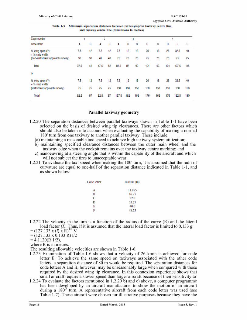
Parallel taxiway geometry 1.2.20 The separation distances between parallel taxiways shown in Table 1-1 have been
selected on the basis of desired wing tip clearances. There are other factors which should also be taken into account when evaluating the capability of making a normal 180' turn from one taxiway to another parallel taxiway. These include:
(a) maintaining a reasonable taxi speed to achieve high taxiway system utilization; b) maintaining specified clearance distances between the outer main wheel and the
taxiway edge when the cockpit remains over the taxiway centre marking; and c) manoeuvring at a steering angle that is within the capability of the aircraft and which
will not subject the tires to unacceptable wear. 1.2.21 To evaluate the taxi speed when making the 180' turn, it is assumed that the radii of
curvature are equal to one-half of the separation distance indicated in Table 1-1, and as shown below:
1.2.22 The velocity in the turn is a function of the radius of the curve (R) and the lateral
load factor (I). Thus, if it is assumed that the lateral load factor is limited to 0.133 g: V = (127.133 x (f) x R)1/2
= (127.133 x 0.133 R)1/2
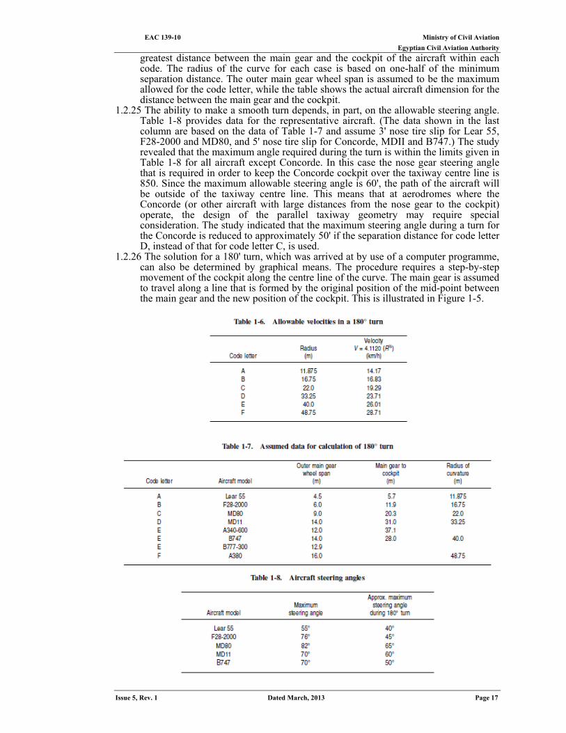
= 4.1120(R 1/2), where R is in metres. The resulting allowable velocities are shown in Table 1-6. 1.2.23 Examination of Table 1-6 shows that a velocity of 26 km/h is achieved for code
letter E. To achieve the same speed on taxiways associated with the other code letters, a separation distance of 80 m would be required. The separation distances for code letters A and B, however, may be unreasonably large when compared with those required by the desired wing tip clearance. In this connexion experience shows that small aircraft require a slower speed than larger aircraft because of their sensitivity to
1.2.24 To evaluate the factors mentioned in 1.2.20 b) and c) above, a computer programme has been developed by an aircraft manufacturer to show the motion of an aircraft during a 180Ο turn. A representative aircraft from each code letter was used (see Table 1-7). These aircraft were chosen for illustrative purposes because they have the
Ministry of Civil Aviation EAC 139-10 Egyptian Civil Aviation Authority
Issue 5, Rev. 1 Dated March, 2013 Page 17
greatest distance between the main gear and the cockpit of the aircraft within each code. The radius of the curve for each case is based on one-half of the minimum separation distance. The outer main gear wheel span is assumed to be the maximum allowed for the code letter, while the table shows the actual aircraft dimension for the distance between the main gear and the cockpit.
1.2.25 The ability to make a smooth turn depends, in part, on the allowable steering angle. Table 1-8 provides data for the representative aircraft. (The data shown in the last column are based on the data of Table 1-7 and assume 3' nose tire slip for Lear 55, F28-2000 and MD80, and 5' nose tire slip for Concorde, MDII and B747.) The study revealed that the maximum angle required during the turn is within the limits given in Table 1-8 for all aircraft except Concorde. In this case the nose gear steering angle that is required in order to keep the Concorde cockpit over the taxiway centre line is 850. Since the maximum allowable steering angle is 60', the path of the aircraft will be outside of the taxiway centre line. This means that at aerodromes where the Concorde (or other aircraft with large distances from the nose gear to the cockpit) operate, the design of the parallel taxiway geometry may require special consideration. The study indicated that the maximum steering angle during a turn for the Concorde is reduced to approximately 50' if the separation distance for code letter D, instead of that for code letter C, is used.
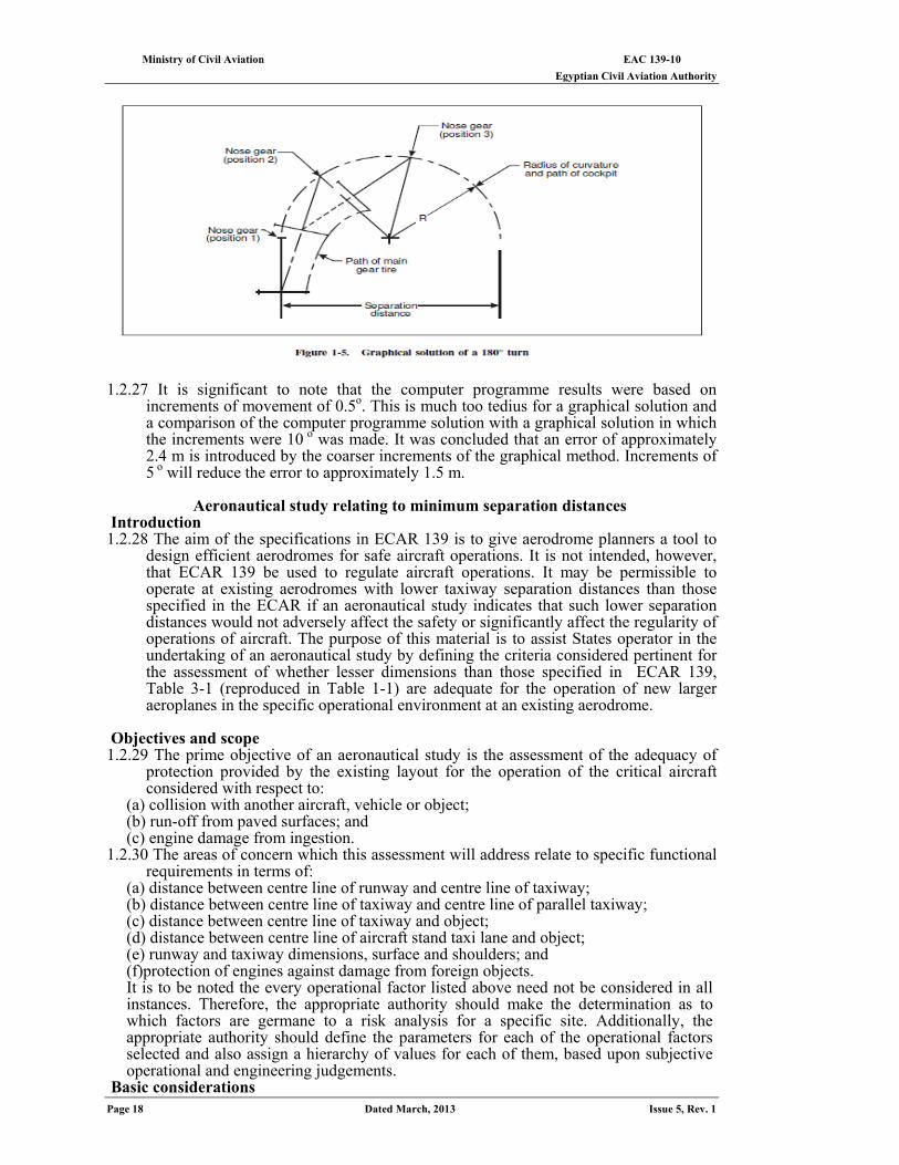
1.2.26 The solution for a 180' turn, which was arrived at by use of a computer programme, can also be determined by graphical means. The procedure requires a step-by-step movement of the cockpit along the centre line of the curve. The main gear is assumed to travel along a line that is formed by the original position of the mid-point between the main gear and the new position of the cockpit. This is illustrated in Figure 1-5.
EAC 139-10 Ministry of Civil Aviation Egyptian Civil Aviation Authority
Page 18 Dated March, 2013 Issue 5, Rev. 1
1.2.27 It is significant to note that the computer programme results were based on
increments of movement of 0.5o. This is much too tedius for a graphical solution and a comparison of the computer programme solution with a graphical solution in which the increments were 10 o was made. It was concluded that an error of approximately 2.4 m is introduced by the coarser increments of the graphical method. Increments of 5 o will reduce the error to approximately 1.5 m.
Aeronautical study relating to minimum separation distances
Introduction 1.2.28 The aim of the specifications in ECAR 139 is to give aerodrome planners a tool to
design efficient aerodromes for safe aircraft operations. It is not intended, however, that ECAR 139 be used to regulate aircraft operations. It may be permissible to operate at existing aerodromes with lower taxiway separation distances than those specified in the ECAR if an aeronautical study indicates that such lower separation distances would not adversely affect the safety or significantly affect the regularity of operations of aircraft. The purpose of this material is to assist States operator in the undertaking of an aeronautical study by defining the criteria considered pertinent for the assessment of whether lesser dimensions than those specified in ECAR 139, Table 3-1 (reproduced in Table 1-1) are adequate for the operation of new larger aeroplanes in the specific operational environment at an existing aerodrome.
Objectives and scope 1.2.29 The prime objective of an aeronautical study is the assessment of the adequacy of
protection provided by the existing layout for the operation of the critical aircraft considered with respect to:
(a) collision with another aircraft, vehicle or object; (b) run-off from paved surfaces; and (c) engine damage from ingestion.
1.2.30 The areas of concern which this assessment will address relate to specific functional requirements in terms of:
(a) distance between centre line of runway and centre line of taxiway; (b) distance between centre line of taxiway and centre line of parallel taxiway; (c) distance between centre line of taxiway and object; (d) distance between centre line of aircraft stand taxi lane and object; (e) runway and taxiway dimensions, surface and shoulders; and (f)protection of engines against damage from foreign objects. It is to be noted the every operational factor listed above need not be considered in all instances. Therefore, the appropriate authority should make the determination as to which factors are germane to a risk analysis for a specific site. Additionally, the appropriate authority should define the parameters for each of the operational factors selected and also assign a hierarchy of values for each of them, based upon subjective operational and engineering judgements.
Basic considerations
Ministry of Civil Aviation EAC 139-10 Egyptian Civil Aviation Authority
Issue 5, Rev. 1 Dated March, 2013 Page 19
1.2.31 Operational experience with large aircraft at aerodromes not designed to the specifications dictated by that aircraft type has shown that a safe and regular operation is feasible, though possibly conditional to specific measures being implemented (e.g. the use of selected taxi routings, designated aircraft stand taxi lanes, etc.). This may be due to the fact that there are a variety of adverse factors that are not necessarily accountable for the operational environment at a certain aerodrome. Furthermore, analyses of accident and incident statistics do not indicate causes being related to basically inadequate margins as provided by the specifications in ECAR 139. It may thus be assumed that the above considerations similarly apply to the operation of new larger aeroplanes, subject to the conditions resulting from the aeronautical study.
Assessment aspects 1.2.32 An aeronautical study will consist essentially of a risk analysis based on pertinent
criteria to assess: (a) probability of collision; (b) probability of run-off; and (c) risk of engine ingestion. The majority of criteria being qualitative in nature, the assessment of risk levels cannot be expressed in absolute or quantitative terms. For the outcome of the study to be meaningful, it should be complemented by operational and engineering judgements. This suggests that the appropriate authority should consult with the aircraft operator when carrying out the assessment.
1.2.33 Referring to collision risk assessment which addresses the separation/clearance distances provided, the relative risk level (expressed in terms of probability of a collision to occur) is generally considered to increase locally on the movement area in the following order of priority: runway → taxiway→ apron taxiway → aircraft stand taxi lane
The increase in risks is attributed to: (a) decreasing accounting for aircraft deviations from the centre line/guideline and
associated incremental margins as specified by the rationale; (b) increasing density of vehicles and objects; and (c) increasing complexity of layouts giving rise to pilot distraction, confusion,
misinterpretation, etc. 1.2.34 A crucial criterion for assessing the adequacy of existing separation/clearance
distances for safe and regular operation of new larger aeroplanes is the accuracy with which aircraft taxi relative to the centre line/guideline on runways and taxiways:
(a) on straight portions; and (b) on taxiway curves.
1.2.35 The following factors can impact on the accuracy achieved in day-to-day operational environments and require, therefore, a detailed examination as applicable:
(a) quality of guidelines (marking and lighting); (b) quality of signs; (c) visibility conditions; (d) day or night; (e) surface state (dry, wet, contaminated by snow/ice); (f) taxi speed; (g) pilots' attention; (h) pilots' technique of negotiating turns; (i) wind effects (cross-wind); and (j) aircraft handling characteristics.
1.2.36 It is emphasized in this context that the provision of taxiing guidance, i.e. marking, lighting and signs which are adequately conspicuous in all operational conditions, together with good surface friction conditions, are considered paramount for achieving a high degree of taxiing accuracy. This is substantiated by the fact that the pilot of a large aeroplane, being unable to see the wing tips, will have to rely primarily on the guideline, the accurate tracking of which will guarantee proper wing tip clearance.
1.2.37 Good surface friction characteristics are required because nose wheel steering effectiveness can become significantly degraded with large aeroplanes whenever the
EAC 139-10 Ministry of Civil Aviation Egyptian Civil Aviation Authority
Page 20 Dated March, 2013 Issue 5, Rev. 1
surface is other than dry, thereby challenging the execution of controlled turns. This is particularly true in the presence of a strong cross-wind.
1.2.38 The rationale used for determining separation distances assumes a lateral deviation value of 4.5 m from the centre line for taxiways/apron taxiways on either straight or curved portions. For aircraft stand taxi lanes the respective value is 2.5 m and is referred to as gear deviation.
1.2.39 Taxiway deviation studies, using a representative mix of aircraft types, including large aeroplanes, were conducted at two European airports. Results suggest that in favourable operating conditions (i.e. positive guidance provided by centre line lighting and marking and good surface friction characteristics) the mean deviation of main gears of aircraft from the centre line on straight taxiway portions is considerably less than 4.5 m. It should be noted here, however, that the value of maximum deviation of main gears of most aircraft reached the 8 to 10 m range depending on aircraft type. With these provisions, a reduction of the deviation value accounted for in an aeronautical study appears acceptable relative to straight portions of taxiways, whereas the specified value should be retained if the above conditions are not met.
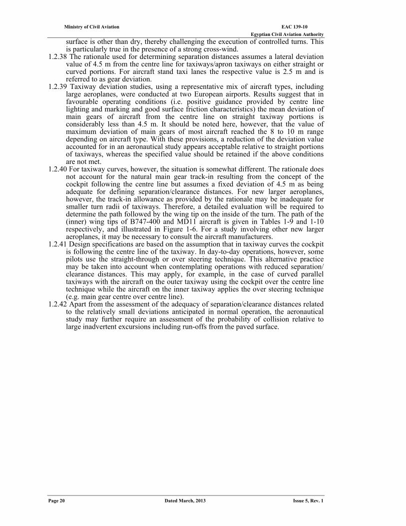
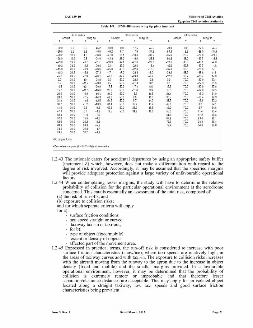
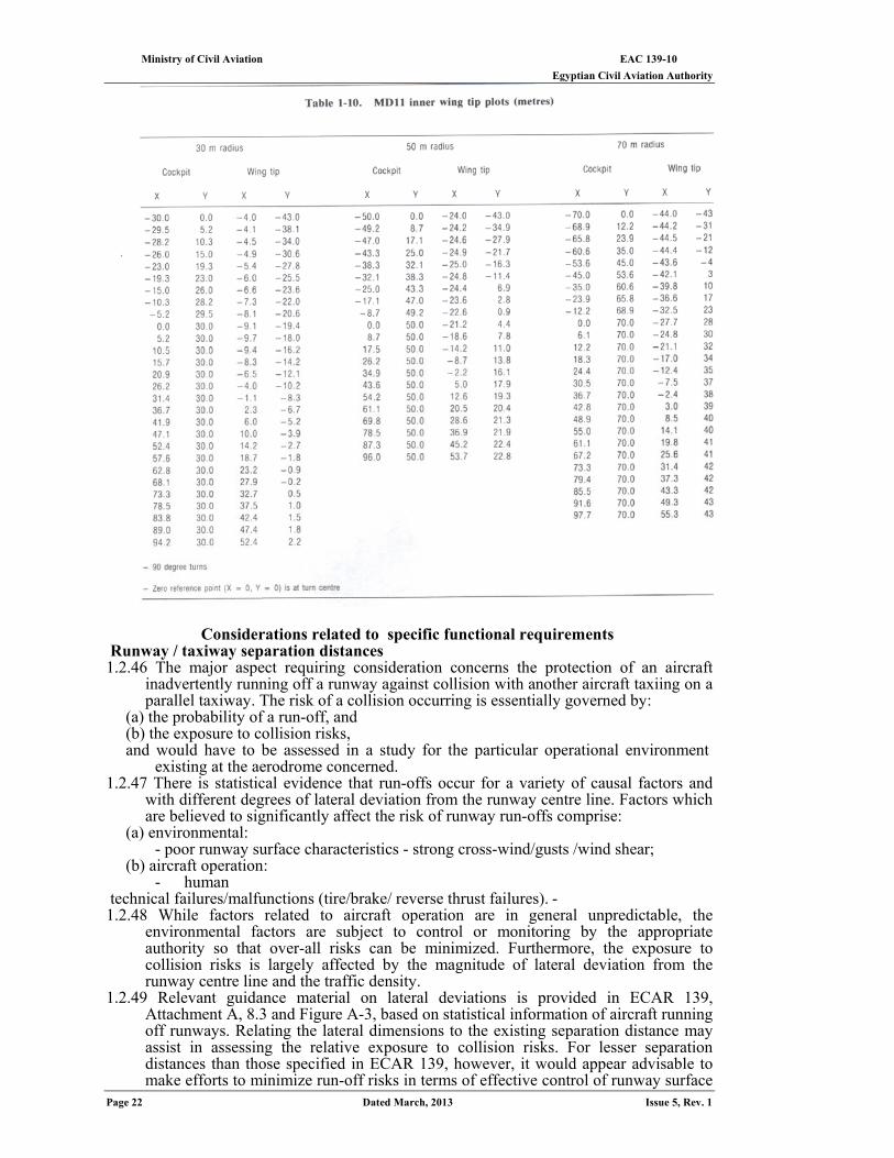
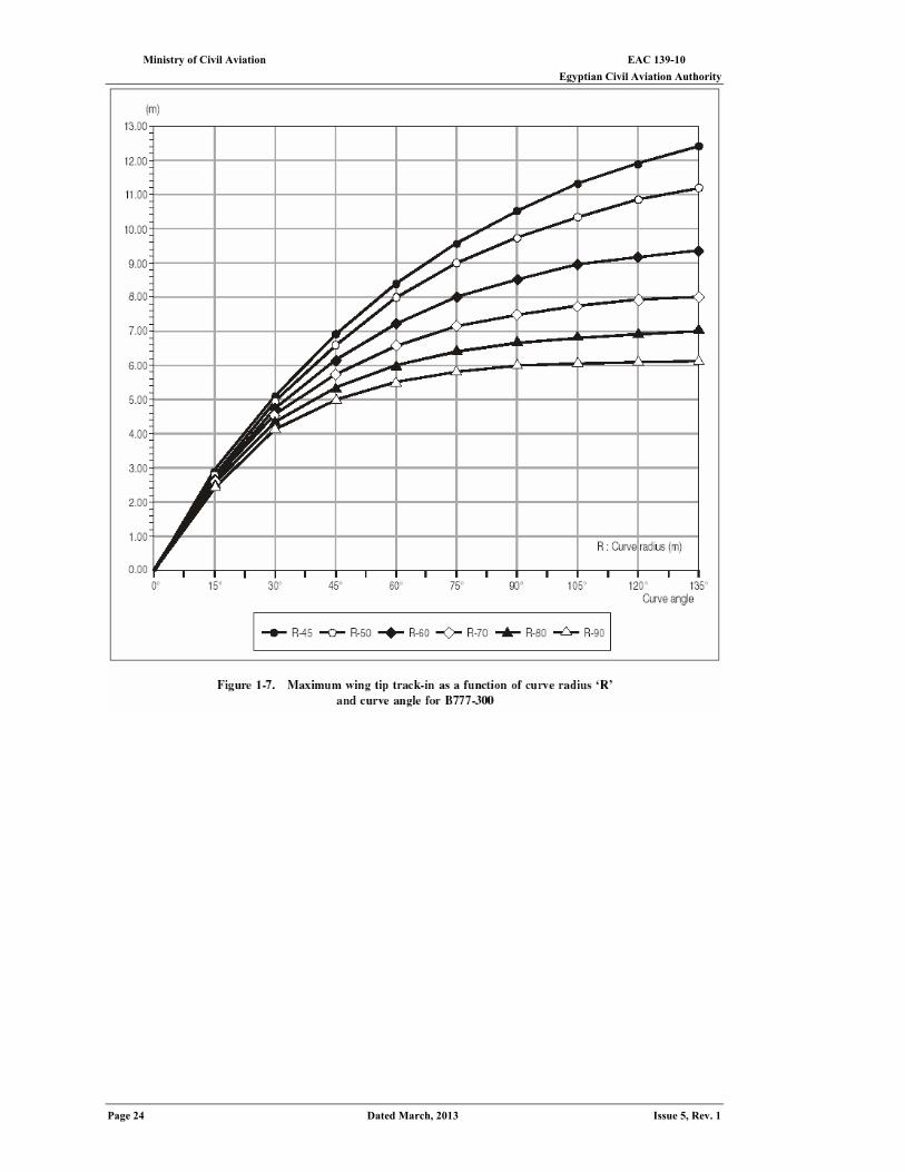
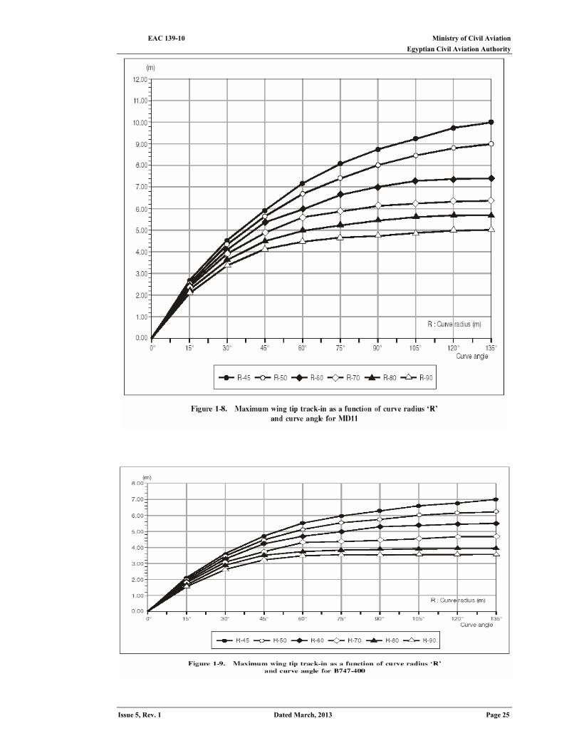
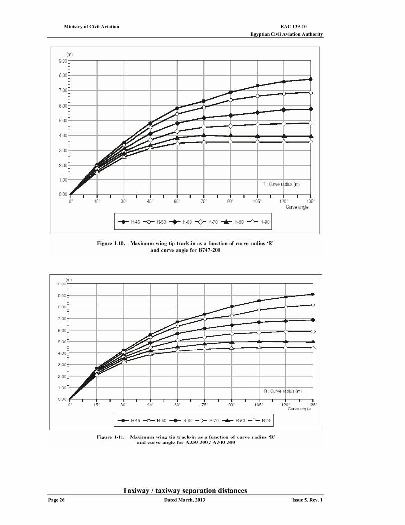
1.2.40 For taxiway curves, however, the situation is somewhat different. The rationale does not account for the natural main gear track-in resulting from the concept of the cockpit following the centre line but assumes a fixed deviation of 4.5 m as being adequate for defining separation/clearance distances. For new larger aeroplanes, however, the track-in allowance as provided by the rationale may be inadequate for smaller turn radii of taxiways. Therefore, a detailed evaluation will be required to determine the path followed by the wing tip on the inside of the turn. The path of the (inner) wing tips of B747-400 and MD11 aircraft is given in Tables 1-9 and 1-10 respectively, and illustrated in Figure 1-6. For a study involving other new larger aeroplanes, it may be necessary to consult the aircraft manufacturers.
1.2.41 Design specifications are based on the assumption that in taxiway curves the cockpit is following the centre line of the taxiway. In day-to-day operations, however, some pilots use the straight-through or over steering technique. This alternative practice may be taken into account when contemplating operations with reduced separation/ clearance distances. This may apply, for example, in the case of curved parallel taxiways with the aircraft on the outer taxiway using the cockpit over the centre line technique while the aircraft on the inner taxiway applies the over steering technique (e.g. main gear centre over centre line).
1.2.42 Apart from the assessment of the adequacy of separation/clearance distances related to the relatively small deviations anticipated in normal operation, the aeronautical study may further require an assessment of the probability of collision relative to large inadvertent excursions including run-offs from the paved surface.
Ministry of Civil Aviation EAC 139-10 Egyptian Civil Aviation Authority
Issue 5, Rev. 1 Dated March, 2013 Page 21
1.2.43 The rationale caters for accidental departures by using an appropriate safety buffer
(increment Z) which, however, does not make a differentiation with regard to the degree of risk involved. Accordingly, it may be assumed that the specified margins will provide adequate protection against a large variety of unfavourable operational factors.
1.2.44 When contemplating lesser margins, the study will have to determine the relative probability of collision for the particular operational environment at the aerodrome concerned. This entails essentially an assessment of the total risk, composed of:
(a) the risk of run-offs; and (b) exposure to collision risks; and for which separate criteria will apply for a):
- surface friction conditions - taxi speed straight or curved - taxiway taxi-in or taxi-out; - for b): - type of object (fixed/mobile) - extent or density of objects - affected part of the movement area.
1.2.45 Expressed in practical terms, the run-off risk is considered to increase with poor surface friction characteristics (snow/ice), where taxi speeds are relatively high, in the areas of taxiway curves and with taxi-in. The exposure to collision risks increases with the aircraft moving from the runway to the apron due to the increase in object density (fixed and mobile) and the smaller margins provided. In a favourable operational environment, however, it may be determined that the probability of collision is extremely remote or improbable and that therefore lesser separation/clearance distances are acceptable. This may apply for an isolated object located along a straight taxiway, low taxi speeds and good surface friction characteristics being prevalent.
EAC 139-10 Ministry of Civil Aviation Egyptian Civil Aviation Authority
Page 22 Dated March, 2013 Issue 5, Rev. 1
Considerations related to specific functional requirements
Runway / taxiway separation distances 1.2.46 The major aspect requiring consideration concerns the protection of an aircraft
inadvertently running off a runway against collision with another aircraft taxiing on a parallel taxiway. The risk of a collision occurring is essentially governed by:
(a) the probability of a run-off, and (b) the exposure to collision risks, and would have to be assessed in a study for the particular operational environment
existing at the aerodrome concerned. 1.2.47 There is statistical evidence that run-offs occur for a variety of causal factors and
with different degrees of lateral deviation from the runway centre line. Factors which are believed to significantly affect the risk of runway run-offs comprise:
(a) environmental: - poor runway surface characteristics - strong cross-wind/gusts /wind shear;
(b) aircraft operation: - human
- technical failures/malfunctions (tire/brake/ reverse thrust failures). 1.2.48 While factors related to aircraft operation are in general unpredictable, the
environmental factors are subject to control or monitoring by the appropriate authority so that over-all risks can be minimized. Furthermore, the exposure to collision risks is largely affected by the magnitude of lateral deviation from the runway centre line and the traffic density.
1.2.49 Relevant guidance material on lateral deviations is provided in ECAR 139, Attachment A, 8.3 and Figure A-3, based on statistical information of aircraft running off runways. Relating the lateral dimensions to the existing separation distance may assist in assessing the relative exposure to collision risks. For lesser separation distances than those specified in ECAR 139, however, it would appear advisable to make efforts to minimize run-off risks in terms of effective control of runway surface
Ministry of Civil Aviation EAC 139-10 Egyptian Civil Aviation Authority
Issue 5, Rev. 1 Dated March, 2013 Page 23
friction characteristics and reliable reporting of wind and, where applicable, runway surface friction characteristics. Accordingly, aircraft operators can contribute to minimizing run-off risks by the application of operational restrictions commensurate with reported conditions.
EAC 139-10 Ministry of Civil Aviation Egyptian Civil Aviation Authority
Page 24 Dated March, 2013 Issue 5, Rev. 1
Ministry of Civil Aviation EAC 139-10 Egyptian Civil Aviation Authority
Issue 5, Rev. 1 Dated March, 2013 Page 25
EAC 139-10 Ministry of Civil Aviation Egyptian Civil Aviation Authority
Page 26 Dated March, 2013 Issue 5, Rev. 1
Taxiway / taxiway separation distances
Ministry of Civil Aviation EAC 139-10 Egyptian Civil Aviation Authority
Issue 5, Rev. 1 Dated March, 2013 Page 27
1.2.50 The separation distances specified by the rationale for parallel taxiways are intended to provide a safe wing tip clearance by accounting for the anticipated deviation of a manoeuvring aircraft from the taxiway centre line, in terms of:
(a) taxiing accuracy achieved in day-to-day operation; and (b) inadvertent excursions/run-offs. A study on whether lesser distances provide adequate safety margins in the operational environment of an existing aerodrome layout will require an assessment of the risk of collision which, owing to different levels involved, should be related to:
(1) straight parallel taxiways; and (2) taxiway curves.
In either case, the risk of collision between two aircraft on parallel taxiways is determined primarily by the probability of an inadvertent major excursion by an aircraft from the taxiway centre line.
1.2.51 In contrast, taxiing accuracy per se is not considered to affect the collision risk to a critical extent in the case of straight parallel taxiways.
1.2.52 On taxiway curves, however, taxiing accuracy becomes a critical element in terms of collision risks for the various reasons outlined in 1.2.32 through 1.2.45. Accordingly, the trajectories of the wing tips of two large aircraft must be established.
1.2.53 When contemplating lesser separation distances, careful consideration must be given to the various factors affecting taxiing accuracy (1.2.32 through 1.2.45), in particular taxiway curves. In this regard, the maintenance of good surface friction characteristics under all environmental circumstances is considered a dominant prerequisite for minimizing:
(a) lateral deviations through proper nose-wheel steering and wheel-braking effectiveness; and
(b) risks of run-off. Accordingly, the over-all risk would be reduced essentially to inadvertent major excursions which may result from unpredictable technical failures affecting the steering capability of an aircraft (e.g. nose-wheel steering). The assessment of the over-all risk would thus consist of: (a) the probability of occurrence of a technical failure leading to a major excursion; and, (b) the exposure to collision risks subject to traffic density. In the case of a) above, however, there is no indication that the probability rate of mechanical failures would be significant.
Taxiway / object separation distances 1.2.54 The risk considerations and the prerequisites related to reduced separation distances
as outlined in 1.2.50 through 1.2.53 will similarly apply to assessing the adequacy of actual separation distances provided at an existing aerodrome between the taxiway centre line and objects. As far as the exposure to risks of collision is concerned, however, particular attention appears warranted with respect to:
(a) the nature of objects (fixed or mobile); (b) the size (isolated or extended); and (c) the location relative to straight portions of taxiways or taxiway curves.
1.2.55 It is reiterated that obstacles situated close to taxiway curves and adjacent areas will require particular examination. This includes not only consideration of wing tip clearances but also the possibility of impingement of jet wake on the object as a result of aircraft turning direction at an intersection.
Apron taxiway / object separation distances 1.2.56 In general, the apron is considered an area of high activity involving a changing
pattern of obstacles of fixed/mobile and permanent or temporary nature in a variable operating environment. Accordingly, aircraft operating along an apron taxiway may be exposed to incomparably higher risks of collision as opposed to aircraft taxiing on a standard taxiway, margins accounted for by the formula in terms of deviation and increment being the same. This is actually evidenced by the comparatively high rate of reported incidents occurring on aprons, which is a matter of continuing concern. There is, however, no indication of the incidents being related to basic inadequacies of the specified minimum separation distances.
EAC 139-10 Ministry of Civil Aviation Egyptian Civil Aviation Authority
Page 28 Dated March, 2013 Issue 5, Rev. 1
1.2.57 Nevertheless, it may be reasonably assumed that at an aerodrome where lesser separation is provided, the potential for incidents to occur will increase unless a set of specific requirements relating to all critical elements involved in apron activities is fulfilled.
1.2.58 It is considered that risks of collision relate predominantly to mobile objects which may infringe upon clearance distances relative to taxiing aircraft. Accordingly, a basic requirement would be to segregate the operating area of an aircraft from the respective area intended to be used by mobile objects (e.g. servicing vehicles and equipment facilities). Specifically this would include:
(a) for the aircraft: - taxi guidelines (marking and lighting);
(b) for mobile objects: - apron safety lines subpart h ECAR 139. - service road boundary lines - procedures and regulations to ensure discipline.
1.2.59 Concerning taxi guidance on aprons, it is of paramount importance, in order to minimize the risk of major excursions, that the pilot is provided with a conspicuous and unambiguous guideline which is visible continuously in all prevailing operating conditions. This guideline is crucial for pilots of large aircraft who, being unable to routinely observe the wing tip and having difficulty judging small clearances, are bound to keep track with designated guidelines as closely as practicable. While doing so, pilots will have to rely on safe taxiing at normal taxi speed.
1.2.60 To ensure accurate manoeuvring and prevent large deviations, consequential to lack of nose wheel steering or braking effectiveness, the provision of good surface friction characteristics is equally important, notably where high cross-winds are encountered. There have been cases where the nose wheel steering force was marginal to balance the moment due to aerodynamic side forces caused by cross-wind.
Aircraft stand taxi lane / object separation distances 1.2.61 The preceding apron-oriented risk aspects and functional requirements are equally
valid for separation distances between aircraft stand taxi lane centre lines and objects, though with a much stronger emphasis.
1.2.62 From an operational point of view, the separation distance as specified by the formula in terms of a reduced gear deviation allowance and safety buffer is rated as rather marginal relative to an operating environment where the exposure to collision risks is normally greatest and the accuracy of aircraft manoeuvring is most demanding. Reducing the specified values, therefore, should be considered as a last resort only, conditional to a study scrutinizing all risk aspects discussed in this section as applicable to the most unfavourable operating conditions representative of the aerodrome concerned. In conducting the study, consultation with the aircraft operator is considered essential to ascertain whether the operational aircraft parameters assumed in the study are realistic.
Runway and taxiway dimensions, surface and shoulders 1.2.63 An aeronautical study should further examine the level of protection provided by
existing physical layouts against run-offs from pavements. This relates in the first place to the width of runways and taxiways and associated wheel-to-edge clearances.
(a) Width of runways. Indications from operational experience are that a total width of 60 m is needed to achieve a reasonable level of safety with large aeroplanes in any given operating environment. The total paved width can consist of either 60 m of full bearing strength or 45 m of full bearing strength, with 7.5 m shoulders each side of adequate bearing strength for occasional passages.
(b) Width of taxiways. The specified wheel-to-edge clearance of 4.5 m for code letter E is considered a minimum. Accordingly, the width of taxiways should provide this clearance, in particular on curves and at intersections, accounting for the appropriate operational methods of tracking guidelines applied by pilots.
Protection of engines against foreign object damage 1.2.64 The rate of damage caused to engines from ingesting foreign objects is substantial
and, therefore, a matter of continuing concern. With new larger aeroplanes equipped
Ministry of Civil Aviation EAC 139-10 Egyptian Civil Aviation Authority
Issue 5, Rev. 1 Dated March, 2013 Page 29
with more powerful engines, the problem is likely to be aggravated. Protection of the taxiway shoulders extending laterally at least to the outer engine is therefore needed. Similarly, it should be ascertained whether the type of surface of the shoulder is adequate to resist erosion from engine blast.
1.2.65 Reserved
Notification 1.2.66 The fact that recommended separation clearance distances are not provided at
certain locations of the movement area at a particular airport should be appropriately identified in the Aerodrome Chart -ICAO (Annex 4, Chapter 13 refers) for operational evaluation by aircraft operators and pilots.
The effect of new larger aero planes on existing airports
1.2.67 To meet the needs of an ever changing aviation industry, succeeding generations of larger aeroplanes have been introduced. Experience gained through the introduction of these aeroplanes has taught airport planners that adequate planning in the initial design of an airport is vital. However, in spite of the best efforts of airport planners, a facility developed for the current generation of aeroplanes may not be adequate for succeeding generations. In order to minimize any impact on capacity, airports would need to be expanded and developed to accommodate such new larger aeroplanes.
1.2.68 With a view to complying with applicable specifications, airport planners and engineers have to explore all avenues while undertaking the rehabilitation of existing facilities. Often, after due consideration of all options, the physical limitations of the existing facilities may leave the airport operator with no choice but to implement operational restrictions.
Taxiway minimum separation distances
1.2.69 As stated in 1.2.46, the main principle govern-in runway/taxiway separation distances is that the wing tip of a taxiing aeroplane should not penetrate the strip of the associated runway. This principle is especially relevant when it is planned to operate new aircraft with greatly increased wingspans at existing airports which were not designed to accommodate such aircraft. Care must be taken to ensure that the increased wingspan of a new larger aircraft does not increase the risk of collision with another aircraft taxiing on a parallel taxiway if the larger aircraft inadvertently runs off a runway, and that ILS critical and sensitive areas are protected. Where the wingspan of an aeroplane on a taxiway penetrates the associated runway strip or the safety zone of a parallel runway, appropriate operational restrictions, such as the taxiway not being used by an aeroplane of such large wingspan, will have to be considered. In most cases, to maintain aerodrome capacity, simultaneous operations of smaller aeroplanes that would not infringe upon the safety zones of the more demanding aeroplanes may be considered, after due study. For instance, at existing aerodromes with runway and taxiway separation distances complying with code letter E specifications, it may be permissible to operate a code letter E or smaller aeroplane on the existing parallel taxiway while a code letter F aeroplane is using the runway.
1.2.70 However, the minimum separation distance between a code letter E runway and parallel taxiway may not provide adequate length for a link taxiway, connecting the parallel taxiway and the runway, to permit safe taxiing of a code letter F aircraft behind an aircraft holding short of the runway at the holding position. To permit such operations, the parallel taxiway should be so located as to comply with the requirements of ECAR 139 Tables 3-1 and 3-2, considering the dimensions of the most demanding aeroplane in a given aerodrome code. For example, at a code E aerodrome, this separation would be equal to the sum of the distance of the runway holding position from the runway centre line, plus the overall length of the most demanding aeroplane, and the taxiway-to-object distance specified in column E of Table 1-1.
1.2.71 At issue is the need to provide adequate clearances on an existing airport in order to
operate a new larger aircraft with the minimum risk possible. If the clear-acne distances given ECAR 139 cannot be met, then an aeronautical study should be
EAC 139-10 Ministry of Civil Aviation Egyptian Civil Aviation Authority
Page 30 Dated March, 2013 Issue 5, Rev. 1
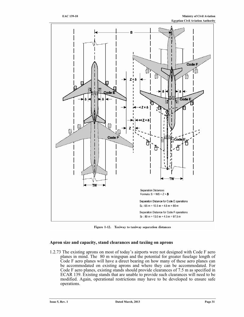
conducted to ensure operational safety and to ascertain what, if any, operational restrictions must be implemented to maintain safety (see Figure 1-12).
1.2.72 In order to minimize such restrictions, when a new facility is planned for addition to
the existing airport infrastructure, it would be prudent to apply the basic clearance distance concept adopted in the development of the specifications found in ECAR 139. An example of the application of this concept would be: An airport with an aerodrome reference code E is planning to develop a new link taxiway for code F operations, adjacent to an existing code E taxiway. What should be the separation between them? If both taxiways are to be used for simultaneous code F aero plane operations (provided all other relevant requirements are satisfactorily met) then the minimum separation distance should be that specified for code F in ECAR 139, Table 3-1, column 10.
If the existing taxiway is to be used by code E aircraft only, then the new code F taxiway may be located as follows:
Minimum separation distance: (½ WSE + ½ WSF) + C + ZF where WS is the wing span, C is the applicable wheel-to-pavement edge clearance (4.5 m in this case) and ZF is the safety margin (13 m) for Code F – the most demanding code. In this case, airport capacity may be slightly reduced should there be a need for two code F aero planes to use these taxi-ways simultaneously since the existing taxiway is not in accordance with code F specifications. Where such a philosophy is implemented with respect to other facilities, a similar approach may be adopted, provided the values of the wheel-to-taxiway edge clearance and wing tip clearance used are those for the higher code letter.
Ministry of Civil Aviation EAC 139-10 Egyptian Civil Aviation Authority
Issue 5, Rev. 1 Dated March, 2013 Page 31
Apron size and capacity, stand clearances and taxiing on aprons 1.2.73 The existing aprons on most of today’s airports were not designed with Code F aero
planes in mind. The 80 m wingspan and the potential for greater fuselage length of Code F aero planes will have a direct bearing on how many of these aero planes can be accommodated on existing aprons and where they can be accommodated. For Code F aero planes, existing stands should provide clearances of 7.5 m as specified in ECAR 139. Existing stands that are unable to provide such clearances will need to be modified. Again, operational restrictions may have to be developed to ensure safe operations.
EAC 139-10 Ministry of Civil Aviation Egyptian Civil Aviation Authority
Page 32 Dated March, 2013 Issue 5, Rev. 1
1.2.74 Adequate clearances behind parked or holding aero planes should also be provided. This issue is impacted not only by the wingspan of the taxiing aero planes but also the fuselage length of the parked aero planes. While the 80 m wingspan limit of Code F is a defining criterion, the fuselage length of these aero planes will also have a direct bearing on their effect on other taxiing aero planes. There-fore, while aero planes with a wingspan of almost 80 m may be faced with operational restrictions due to their wing-spans, it may be also necessary to implement operational restrictions in those cases where the increased fuselage length of code F aircraft may cause reduced clearances with other taxiing aircraft.
1.3 Rapid Exit Taxiways
General 1.3.1 A rapid exit taxiway is a taxiway connected to a runway at an acute angle and
designed to allow landing aeroplanes to turn off at higher speeds than are achieved on other exit taxiways, thereby minimizing runway occupancy time.
1.3.2 A decision to design and construct a rapid exit taxiway is based upon analyses of the existing and contemplated traffic. The main purpose of these taxiways is to minimize aircraft runway occupancy and thus increase aerodrome capacity. When the design peak hour traffic density is approximately less than 25 operations (landings and take-offs), the right angle exit taxiway may suffice. The construction of this right angle exit taxiway is less expensive and when properly located along the runway achieves an efficient flow of traffic.
1.3.3 The establishment of a single world-wide standard for the design of rapid exit taxiways has many obvious advantages. Pilots become familiar with the configuration and can expect the same results when landing at any aerodrome with these facilities. Accordingly, design parameters have been established in ECAR 139 for a grouping of exit taxiways associated with a runway where the code number is I or 2 and another grouping for code number 3 or 4. Since the introduction of rapid exit taxiways, additional field tests and studies have been conducted to determine taxiway utilization, exit taxiway location and design, and runway occupancy time. Evaluation of such material has led to the development of exit taxiway location and design criteria based on specified aircraft populations at relatively high speeds.
1.3.4 There is some difference of opinion with respect to the speed at which pilots negotiate rapid exit taxiways. While it has been inferred from some studies that these taxiways are normally used at a speed not higher than 46 km/h (25 kt) and even in some cases at lower speeds when poor braking action or strong crosswinds are encountered, measurements at other aerodromes have shown that they are being used at speeds of over 92 km/h (49 kt) under dry conditions. For safety reasons 93 km/h (50 kt) has been taken as the reference for determining curve radii and adjacent straight portions for rapid exit taxiways where the code number is 3 or 4. For computing the optimum exit locations along the runway, however, the planner will choose a lower speed. In any case, the optimum utilization of rapid exits requires pilot co-operation. Instruction on the design of and benefits to be obtained from use of these taxiways may increase their use.
Location and number of exit taxiways
Planning criteria 1.3.5 The following basic planning criteria should be considered when planning rapid exit
taxiways to ensure that, wherever possible, standard design methods and con-figurations are used:
a) For runways exclusively intended for landings, a rapid exit taxiway should be
provided only if dictated by the need for reduced runway occupancy times
consistent with minimum inter-arrival spacing's;
b) For runways where alternating landings and departures are conducted, time
separation between the landing aircraft and the following departing aircraft is the
main factor limiting runway capacity;
c) As different types of aircraft require different locations for rapid exit taxiways, the
Ministry of Civil Aviation EAC 139-10 Egyptian Civil Aviation Authority
Issue 5, Rev. 1 Dated March, 2013 Page 33
expected aircraft fleet mix will be an essential criterion; d) The threshold speed, braking ability and operational turn-off speed (Vex) of the
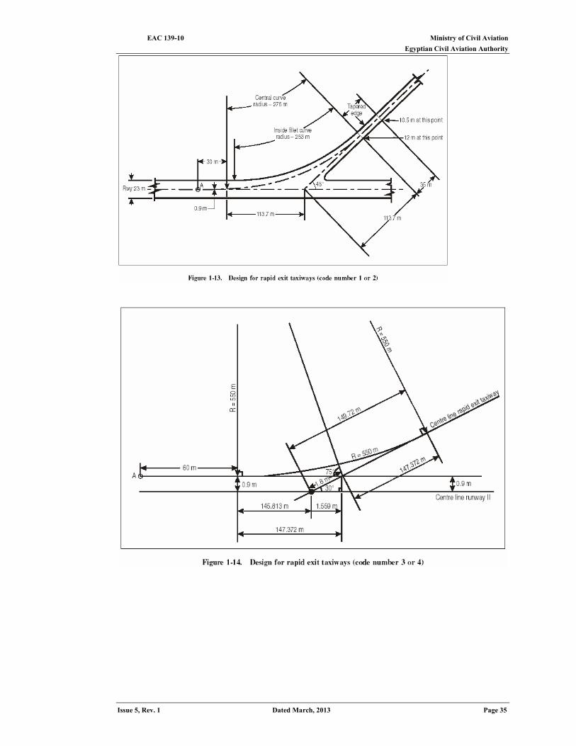
aircraft will determine the location of the exits. 1.3.6 The location of exit taxiways in relation to air-craft operational characteristics is
determined by the deceleration rate of the aircraft after crossing the threshold. To determine the distance from the threshold, the following basic conditions should be taken into account:
a) threshold speed; and b) initial exit speed or turn-off speed at the point of tangency of the central (exit) curve
(point A, Figures 1-13 and 1-14). Design, location and number of rapid exit taxiways 1.3.7 Determining the optimum location and required number of rapid exit taxiways to suit
a particular group of aero planes is recognized as a comparatively complex task owing to the many criteria involved. Although most of the operational parameters are specific to the type of aircraft with respect to the landing man oeuvre and subsequent braked deceleration, there are some criteria which are reasonably independent of the type of aircraft.
1.3.8 Accordingly, a methodology, known as the Three Segment Method, was developed which permits the determination of the typical segmental distance requirements from the landing threshold to the turn-off point based on the operating practices of individual aircraft and the effect of the specific parameters involved. The methodology is based on analytical considerations supplemented by empirical assumptions, as described below.
For the purpose of exit taxiway design, the aircraft are assumed to cross the threshold at an average of 1.3 times the stall speed in the landing configuration at maximum certificated landing mass with an average gross landing mass of about 85 per cent of the maximum. Further, aircraft can be grouped on the basis of their threshold speed at sea level as follows:
Group A - less than 169 km/h (91 kt) Group B - Group B - between 169 km/h (91 kt) and 222 km/h (120 kt)
Group C - Group C - between 224 km/h (121 kt) and 259 km/h (140 kt) Group D - Group D - between 261 km/h (141 kt) and 306 km/h (165 kt),
although the maximum threshold crossing speed of aircraft currently in production is 282 km/h (152 kt). 1.3.10 An analysis of some aircraft indicates that they may be placed in the groups as
follows: Group A DC3 DHC6 DHC7 Group B Avro RJ 100 DC6 DC7 Fokker F27 Fokker F28 HS146 HS748 IL18 IL76 Group C Airbus (A300, A310,A320,A330) B707-320 B727 B737 B747-SP
EAC 139-10 Ministry of Civil Aviation Egyptian Civil Aviation Authority
Page 34 Dated March, 2013 Issue 5, Rev. 1
B757 B767 DC8 (all versions except 61 and 63) DC9 MD80 MD90 DC10-10 L1011-200 DCIO-10 L 10 11-200 Group D A340 B747 B777 DC8 (61 and 63) DC 10-30/40 MD-11 IL62 IL86 IL96 L101 1-500 TU154
1.3.11 The number of exit taxiways will depend on the types of aircraft and number of each
type that operate during the peak period. For example, at a very large aerodrome, most aircraft will likely be in groups C or D. If so, only two exits may be required. On the other hand, an aerodrome having a balanced mixture of all four groups of air-craft may require four exits.
1.3.12 Using the Three Segment Method, the total distance required from the landing threshold to the point of turn-off from the runway centre line can be determined according to the method illustrated in Figure 1-15.
The total distance S is the sum of three distinct segments which are computed separately. Segment 1: Distance required from landing threshold to main gear touchdown (S1). Segment 2: Distance required for transition from main gear touchdown to establish
stabilized braking configuration (S2). Segment 3: Distance required for deceleration in a nor-mal braking mode to a nominal
turnoff speed (S3).
Ministry of Civil Aviation EAC 139-10 Egyptian Civil Aviation Authority
Issue 5, Rev. 1 Dated March, 2013 Page 35

EAC 139-10 Ministry of Civil Aviation Egyptian Civil Aviation Authority
Page 36 Dated March, 2013 Issue 5, Rev. 1
Speed profile: Vth Threshold speed based on 1.3 times the stall speed of assumed landing mass equal to 85
per cent of maximum landing mass. Speed is corrected for ele-vation and airport reference temperature.
Vtd Assumed as Vth – 5 kts (conservative). Speed decay considered representative for most types of aircraft. Vba Assumed brake application speed.
Vth – 15 kts (wheel brakes and/or reverse thrust application).
Vex Nominal turn-off speed: Code number 3 or 4: 30 kts Code number 1 or 2: 15 kts
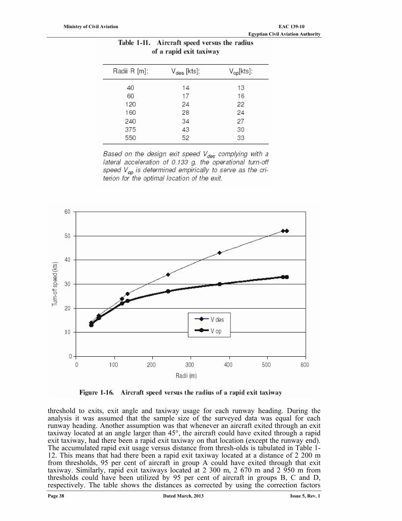
For standard rapid exit taxiways according to Figures 1-13 and 1-14. For other types of exit taxiways see Table 1-11 and Figure 1-16 for turn-off speed.
Distances [in m]: S1 Empirically derived firm distance to mean touch-down point, corrected for downhill slope and tail-wind component where applicable.
Aircraft category C and D: S1 = 450 m Correction for slope: + 50 m / - 0.25% Correction for tailwind: + 50 m / + 5 kts
Aircraft category A and B: S1 = 250 m Correction for slope: + 30 m / - 0.25%
Correction for tailwind: + 30 m / + 5 kts S2 The transition distance is calculated for an assumed transition time (empirical)
t= 10 seconds at an average ground speed of:
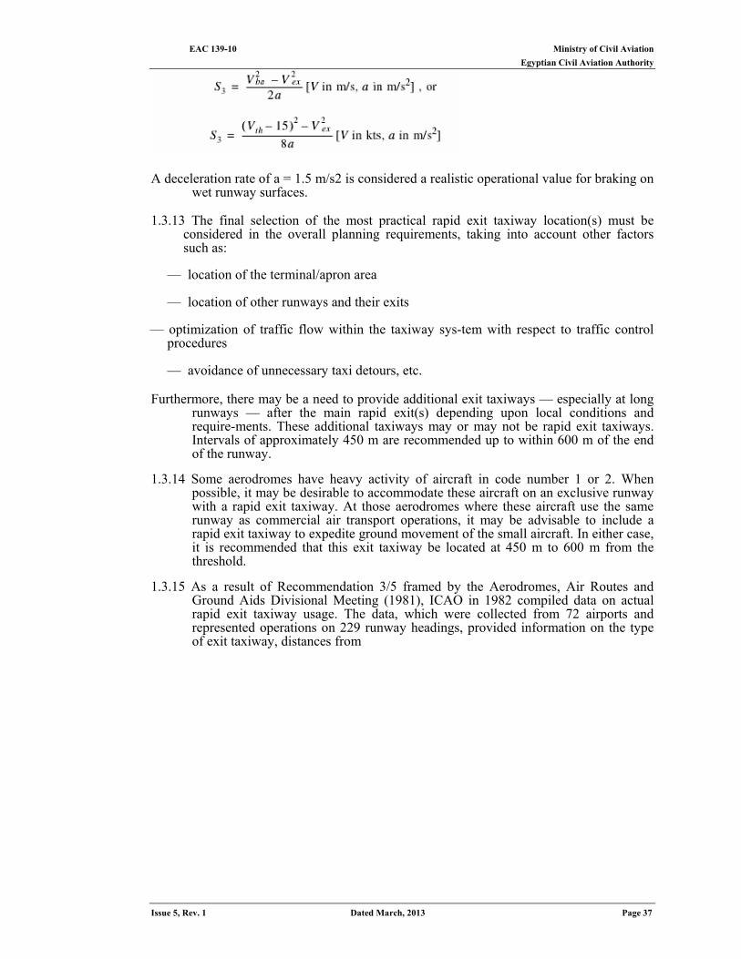
S3 The braking distance is determined based on an assumed deceleration rate
‘a’ according to the following equation:
Ministry of Civil Aviation EAC 139-10 Egyptian Civil Aviation Authority
Issue 5, Rev. 1 Dated March, 2013 Page 37
A deceleration rate of a = 1.5 m/s2 is considered a realistic operational value for braking on
wet runway surfaces. 1.3.13 The final selection of the most practical rapid exit taxiway location(s) must be
considered in the overall planning requirements, taking into account other factors such as:
— location of the terminal/apron area — location of other runways and their exits
— optimization of traffic flow within the taxiway sys-tem with respect to traffic control procedures — avoidance of unnecessary taxi detours, etc.
Furthermore, there may be a need to provide additional exit taxiways — especially at long
runways — after the main rapid exit(s) depending upon local conditions and require-ments. These additional taxiways may or may not be rapid exit taxiways. Intervals of approximately 450 m are recommended up to within 600 m of the end of the runway.
1.3.14 Some aerodromes have heavy activity of aircraft in code number 1 or 2. When
possible, it may be desirable to accommodate these aircraft on an exclusive runway with a rapid exit taxiway. At those aerodromes where these aircraft use the same runway as commercial air transport operations, it may be advisable to include a rapid exit taxiway to expedite ground movement of the small aircraft. In either case, it is recommended that this exit taxiway be located at 450 m to 600 m from the threshold.
1.3.15 As a result of Recommendation 3/5 framed by the Aerodromes, Air Routes and
Ground Aids Divisional Meeting (1981), ICAO in 1982 compiled data on actual rapid exit taxiway usage. The data, which were collected from 72 airports and represented operations on 229 runway headings, provided information on the type of exit taxiway, distances from
EAC 139-10 Ministry of Civil Aviation Egyptian Civil Aviation Authority
Page 38 Dated March, 2013 Issue 5, Rev. 1
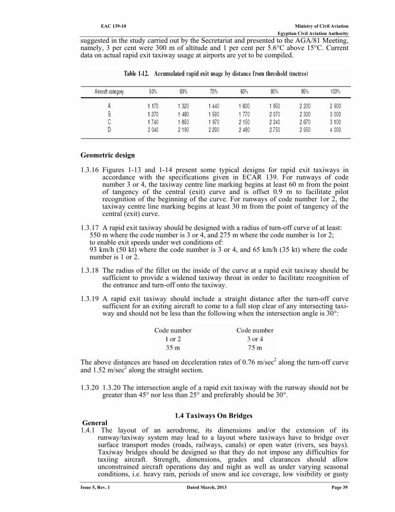
threshold to exits, exit angle and taxiway usage for each runway heading. During the analysis it was assumed that the sample size of the surveyed data was equal for each runway heading. Another assumption was that whenever an aircraft exited through an exit taxiway located at an angle larger than 45°, the aircraft could have exited through a rapid exit taxiway, had there been a rapid exit taxiway on that location (except the runway end). The accumulated rapid exit usage versus distance from thresh-olds is tabulated in Table 1-12. This means that had there been a rapid exit taxiway located at a distance of 2 200 m from thresholds, 95 per cent of aircraft in group A could have exited through that exit taxiway. Similarly, rapid exit taxiways located at 2 300 m, 2 670 m and 2 950 m from thresholds could have been utilized by 95 per cent of aircraft in groups B, C and D, respectively. The table shows the distances as corrected by using the correction factors
Ministry of Civil Aviation EAC 139-10 Egyptian Civil Aviation Authority
Issue 5, Rev. 1 Dated March, 2013 Page 39
suggested in the study carried out by the Secretariat and presented to the AGA/81 Meeting, namely, 3 per cent were 300 m of altitude and 1 per cent per 5.6°C above 15°C. Current data on actual rapid exit taxiway usage at airports are yet to be compiled.
Geometric design 1.3.16 Figures 1-13 and 1-14 present some typical designs for rapid exit taxiways in
accordance with the specifications given in ECAR 139. For runways of code number 3 or 4, the taxiway centre line marking begins at least 60 m from the point of tangency of the central (exit) curve and is offset 0.9 m to facilitate pilot recognition of the beginning of the curve. For runways of code number 1or 2, the taxiway centre line marking begins at least 30 m from the point of tangency of the central (exit) curve.
1.3.17 A rapid exit taxiway should be designed with a radius of turn-off curve of at least:
550 m where the code number is 3 or 4, and 275 m where the code number is 1or 2; to enable exit speeds under wet conditions of: 93 km/h (50 kt) where the code number is 3 or 4, and 65 km/h (35 kt) where the code number is 1 or 2.
1.3.18 The radius of the fillet on the inside of the curve at a rapid exit taxiway should be
sufficient to provide a widened taxiway throat in order to facilitate recognition of the entrance and turn-off onto the taxiway.
1.3.19 A rapid exit taxiway should include a straight distance after the turn-off curve
sufficient for an exiting aircraft to come to a full stop clear of any intersecting taxi-way and should not be less than the following when the intersection angle is 30°:
The above distances are based on deceleration rates of 0.76 m/sec2 along the turn-off curve and 1.52 m/sec2 along the straight section. 1.3.20 1.3.20 The intersection angle of a rapid exit taxiway with the runway should not be
greater than 45° nor less than 25° and preferably should be 30°.
1.4 Taxiways On Bridges General 1.4.1 The layout of an aerodrome, its dimensions and/or the extension of its
runway/taxiway system may lead to a layout where taxiways have to bridge over surface transport modes (roads, railways, canals) or open water (rivers, sea bays). Taxiway bridges should be designed so that they do not impose any difficulties for taxiing aircraft. Strength, dimensions, grades and clearances should allow unconstrained aircraft operations day and night as well as under varying seasonal conditions, i.e. heavy rain, periods of snow and ice coverage, low visibility or gusty
EAC 139-10 Ministry of Civil Aviation Egyptian Civil Aviation Authority
Page 40 Dated March, 2013 Issue 5, Rev. 1
winds. The requirements of taxiway maintenance, cleaning and snow removal should be taken into account when bridges are being designed.
Sitting
1.4.2 For operational and economic reasons the number of bridging structures required and problems related therewith can be minimized by applying the following guidelines:
(a) if possible, the surface modes should be routed so that the least number of runways or taxiways will be affected;
(b) the surface modes should be concentrated so that preferably all can be bridged with a single structure;
(c) a bridge should be located on a straight portion of a taxiway with a straight portion provided on both ends of the bridge to facilitate the alignment of the aeroplanes approaching the bridge;
(d) rapid exit taxiways should not be located on a bridge; and (e) (e)bridge locations that could have an adverse effect upon the instrument landing
system, the approach lighting or runway/taxiway lighting systems should be avoided.
Dimensions
1.4.3 Its purpose and the specifications relevant to the transport mode that it will serve determine the design of the bridge structure. Aeronautical requirements should be met with respect to width and grading, etc. of the taxiway.
1.4.4 The bridge width measured perpendicularly to the taxiway centre line shall not be less than the width of the graded portion of the strip provided for that taxiway, unless a proven method of lateral restraint is provided which shall not be hazardous for aeroplanes for which the taxiway is intended. Therefore minimum width requirements will normally be:
22 m where the code letter is A
25 m where the code letter is B or C 38 m where the code letter is D 44 m where the code letter is E
with the taxiway in the centre of the strip. In the exceptional cases when a curved taxiway
has to be located on the bridge, extra width should be provided to compensate for the unsymmetrical movement of the aircraft by track-in of the main gear.
1.4.5 If the role of the aerodrome in terms of aircraft utilization is not clearly defined or is limited by other physical characteristics, the dimensions of the bridge width to be designed should be related to a higher code letter from the very beginning. This will prevent the aerodrome operator from taking very costly corrective action once a larger aircraft starts to operate on that aerodrome and has to use the taxiway bridge.
1.4.6 The taxiway width on the bridge should be at least as wide as off the bridge. Contrary to the situation in other parts of the taxiway system, the strip on the bridge will normally have a paved surface and serve as fully bearing shoulder. Additionally, the paved strip on the bridge facilitates maintenance and, where necessary, snow clearing work. Furthermore, the paved surface strip provides access to the bridge for rescue and fire fighting vehicles as well as other emergency vehicles.
1.4.7 The efficiency of ground movement operations will be enhanced if aircraft are able to approach and depart from bridges on straight portions of the taxiway. These will enable aircraft to align themselves with the main undercarriage astride the taxiway centre line before crossing the taxiway bridge. The length of the straight section should be at least twice the wheel base (distance from the nose gear to the geometric centre of the main gear) of the most demanding aircraft and not less than 15 m for code letter A 20 m for code letter B 50 m for code letter C, D or E.
It should be noted that possible future aircraft in code E may have a wheel base of 35 m indicating a requirement for a straight distance of 70 m.
Ministry of Civil Aviation EAC 139-10 Egyptian Civil Aviation Authority
Issue 5, Rev. 1 Dated March, 2013 Page 41
Gradients 1.4.8 For drainage purposes normal taxiway transverse slopes are generally provided. If for
other reasons a slope less than 1.5 per cent has been selected, consideration should be given to the provision of sufficient drainage capability on the taxiway.
1.4.9 Ideally the bridge should be level with the adjacent aerodrome terrain. If for other technical reasons the top of the bridge must be higher than the surrounding aerodrome terrain, the adjoining taxiway sections should be designed with slopes which do not exceed the longitudinal gradients specified in Table 1-1.
Bearing strength
1.4.10 A taxiway bridge should be designed to support the static and dynamic loads imposed by the most demanding aircraft expected to use the aerodrome. Future trends of aircraft mass development should be taken into account in specifying the "most demanding aircraft-. Information on future trends is regularly issued by the manufacturers' associations. Incorporation of future requirements may help to avoid costly redesign of bridges due to progress in technology and/or increasing transport demand.
1.4.11 The strength of the bridge should normally be sufficient over the entire width of the graded area of taxiway strip to withstand the traffic of the aeroplanes the taxiway is intended to serve. Minimum width requirements are specified in 1.4.4. A weaker construction is acceptable for parts of the same bridge which have been added to serve vehicular traffic only.
Lateral restraint
1.4.12 When the full load-bearing width provided is less than that of the graded area of the taxiway strip, a proven method of lateral restraint should be provided which shall not be hazardous to aeroplanes for which the taxiway is intended. The lateral restraint system should be provided at the edges of the full load-bearing portion of the strip to prevent the aircraft from falling off the bridge or entering areas of reduced bearing strength. Lateral restraint devices should generally be considered as additional safety measures rather than a means of reducing the full load-bearing width of the taxiway bridge.
1.4.13 The lateral restraint device generally consists of a concrete curb which may serve as a barrier. Two examples of concrete curbs used by States are shown in Figure 1-17. The recommended minimum distance for the location of the lateral restraint device, but a range between 9 and 27 m from the taxiway centre line. However, factors mentioned in should be kept in view when considering the location of lateral restraints. The curb is generally from 20 to 60 cm high, the lowest type of curve being used when the width of the graded area is significantly greater than the width of the taxiway strip.
1.4.14 It may be desirable to provide a second lateral restraint device. This device may consist of a concrete curb or a safety guard rail which is designed for aircraft running off the taxiway but rather as a safety measure for maintenance personnel and vehicles using the bridge.
Blast protection
1.4.15 Where the taxiway passes over another transport mode, some kind of protection against aircraft engine blast may need to be provided. This can be accomplished by light cover construction of perforated material (bars or grid-type elements) capable of braking the initial jet blast to uncritical velocities of the order of 56 km/h. Contrary to closed covers, an open construction does not cause any drainage and loading capacity problems.
1.4.16 The over-all width of the bridge and protected area should be equal to or exceed the blast pattern of the aircraft using the taxiway. This may be determined by reference to the manufacturers' literature on the aircraft concerned.
1.5 Fillets
General 1.5.1 ECAR 139 recommends minimum clearance distances between the outer main
wheel of the aircraft which the taxiway is intended to serve and the edge of the
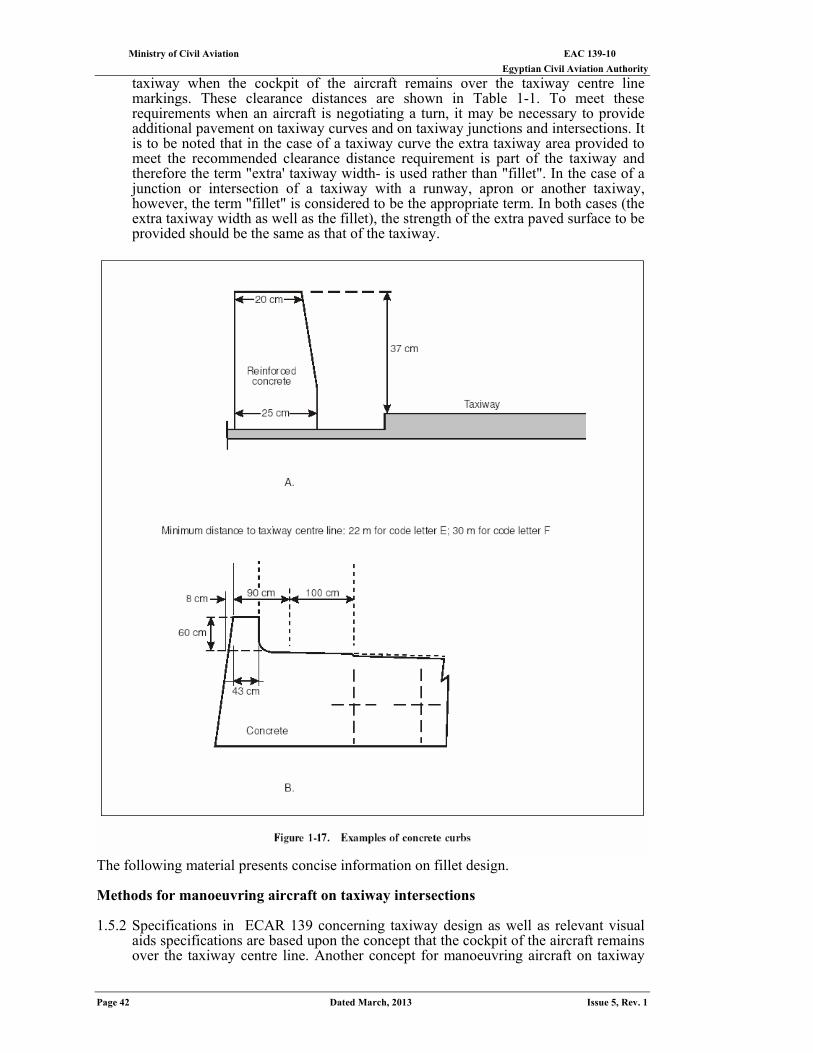
EAC 139-10 Ministry of Civil Aviation Egyptian Civil Aviation Authority
Page 42 Dated March, 2013 Issue 5, Rev. 1
taxiway when the cockpit of the aircraft remains over the taxiway centre line markings. These clearance distances are shown in Table 1-1. To meet these requirements when an aircraft is negotiating a turn, it may be necessary to provide additional pavement on taxiway curves and on taxiway junctions and intersections. It is to be noted that in the case of a taxiway curve the extra taxiway area provided to meet the recommended clearance distance requirement is part of the taxiway and therefore the term "extra' taxiway width- is used rather than "fillet". In the case of a junction or intersection of a taxiway with a runway, apron or another taxiway, however, the term "fillet" is considered to be the appropriate term. In both cases (the extra taxiway width as well as the fillet), the strength of the extra paved surface to be provided should be the same as that of the taxiway.
The following material presents concise information on fillet design. Methods for manoeuvring aircraft on taxiway intersections
1.5.2 Specifications in ECAR 139 concerning taxiway design as well as relevant visual
aids specifications are based upon the concept that the cockpit of the aircraft remains over the taxiway centre line. Another concept for manoeuvring aircraft on taxiway
Ministry of Civil Aviation EAC 139-10 Egyptian Civil Aviation Authority
Issue 5, Rev. 1 Dated March, 2013 Page 43
intersections is based upon offsetting the guideline. Three different ways to ensure that the required clearance distances in Table 1-1 are met are:
(a) by using the taxiway centre line as the aircraft guidelines and providing a fillet; (b) by offsetting the guidelines outwards; (c) by a combination of offset guideline and fillet.
1.5.3 Methods b) and c) would appear to be the more economical solutions but the advantages are not as great as they seem. To obtain the maximum advantage there would have to be a separate guideline for each aircraft type and for both directions on a two way taxiway. Such a multiplicity of lines is impractical particularly when the taxiway is intended to be used at night or during poor visibility conditions and it would thus be necessary to provide a compromise offset guideline which could be used by all aircraft.
1.6 Taxiway Shoulders And Strips
General 1.6.1 A shoulder is an area adjacent to the edge of a paved surface so prepared as to
provide a transition between the pavement and the adjacent surface. The main purpose of the provision of a taxiway shoulder is twofold: to prevent jet engines that overhang the edge of a taxiway from ingesting stones or other objects that might damage the engine and to prevent erosion of the area adjacent to the taxiway. A taxiway strip is an area including a taxiway intended to protect an aircraft operating on the taxiway and to reduce the risk of damage to an aircraft accidentally running off the taxiway.
1.6.2 The widths to be provided for taxiway shoulders and strips are given in Table 1-1. It may be noted that a shoulder 10.5 m wide on both sides of the taxiway, where the code letter is E, is considered to be suitable. This taxiway shoulder width requirement is based on the most critical aircraft operating at this time. Nevertheless, it is desirable to protect a wider area should operations by Boeing 747-400 be planned, as the possibility of potential foreign object damage and the effect of exhaust blast on the taxiway shoulder during break away will be higher than those resulting from Boeing 747-200/300 operations. With respect to a taxiway where the code letter is D, a shoulder 7.5 m wide on both sides is considered to be suitable, assuming that the distance between the outboard engines of the critical aircraft normally using that taxiway will not exceed 30 m.
1.6.3 The surface of the shoulder that abuts the taxiway should be flush with the surface of the taxiway while the surface of the strip should be flush with the edge of the taxiway or shoulder, if provided. For code letter C, D or E, the graded portion of the taxiway strip should not rise more than 2.5 per cent or slope down at a gradient exceeding 5 per cent. The respective slopes for code letter A or B are 3 per cent and 5 per cent. The upward slope is measured with reference to the transverse slope of the adjacent taxiway surface and the downward slope is measured with reference to the horizontal. There should, furthermore, be no holes or ditches tolerated within the graded portion of the taxiway strip. The taxiway strip should provide an area clear of objects which may endanger taxiing aero planes. Consideration will have to be given to the location and design of drains on a taxiway strip to prevent damage to an aircraft accidentally running off a taxiway. Suitably designed drain covers required.
1.6.4 No obstacles should be allowed on either side of a taxiway within the distance shown in Table 1-1 for separation of fixed objects. However, signs and any other objects which, because of their functions, must be maintained within the taxiway strip in order to meet air navigation requirements may remain but they should be constructed and sited in such a manner as to reduce the hazard to an aircraft striking them to a minimum. Such objects should be sited so that they cannot be struck by propellers, engine pods and wings of aircraft using the taxiway.
Treatment
1.6.5 Taxiway shoulders and graded portions of strips provide an obstacle-free area intended to minimize the probability of damage to an aircraft using these areas accidentally or in an emergency. These areas should thus be prepared or constructed so as to reduce the risk of damage to an aircraft running off the taxiway and be
EAC 139-10 Ministry of Civil Aviation Egyptian Civil Aviation Authority
Page 44 Dated March, 2013 Issue 5, Rev. 1
capable of sup-porting access by rescue and fire fighting vehicles and other ground vehicles, as appropriate, over its entire area. When a taxiway is intended to be used by turbine engine aircraft, the jet engines may overhang the edge of the taxiway while the aircraft is taxiing and may then ingest stones or foreign objects from the shoulders. Further, blast from the engines may impinge on the surface adjacent to the taxiway and may dislodge material with consequent hazard to personnel, aircraft and facilities. Certain precautions must therefore be taken to reduce these possibilities. The type of surface of the taxiway shoulder will depend on local conditions and contemplated methods and cost of maintenance. While a natural surface (e.g. turf) may suffice in certain cases, in others, an artificial surface may be required. In any event, the type of surface selected should be such as to avoid the blowing up of debris as well as dust while also meeting the minimum load bearing capability mentioned above.
1.6.6 Under most taxiing conditions, blast velocities are not critical except at intersections where thrusts approach those on breakaway. With the present criteria of up to 25 m wide taxiways, the outboard engines of the larger jets extend beyond the edge of the pavement. For this reason, treatment of taxiway shoulders is recommended to prevent their erosion and to prevent the ingestion of foreign material into jet engines or the blowing of such material into the engines of following aircraft. The material below presents concise information on methods of protection of marginal areas subject to blast erosion and of those areas which must be kept free from debris to prevent ingestion by overhanging turbine engines. Additional information can be found in Appendix 2, 18 to 21.
1.6.7 Studies of engine blast and blast effects have included profile development and velocity contour as related to engine type, aircraft mass and configuration; variation in thrust; and effect of cross-wind. It has been found that the effects of heat associated with the jet wake are negligible. Heat dissipates more rapidly with distance than blast force. Furthermore, personnel, equipment and structures normally do not occupy the upper limits of those areas where heat is generated during jet operations. Objects in the path of a jet blast are acted upon by several forces including the dynamic pressure associated with the impact of gases as they strike the surface, drag forces set up when viscous gases move past an object, and uplift forces caused by either differential pressures or turbulence.
1.6.8 Cohesive soils, when loosened, are susceptible to erosion by jet blast. For these soils, protection that is adequate against the natural erosive forces of wind and rain will normally be satisfactory. The protection must be a kind that adheres to the clay surfacing so that the jet blast does not strip it off. Oiling or chemical treatment of a cohesive soil surface are possible solutions. The cohesion required to protect a surface from blast erosion is small; normally, a plasticity index (PI) of two or greater will suffice. However, if the area is periodically used by ground vehicles with their equipment, a PI of six or more will be necessary. There should be good surface drainage for these areas if equipment moves over them since this type of surface will be softened by pounding. Special consideration must be given to highly plastic cohesive soils subject to more than about 5 per cent shrinkage. For these soils, good drainage is very important since they become extremely soft when wet. When dry, these soils crack and become subject to greater lift forces. Fine, cohesion less soils, which are the most susceptible to erosion by blast, are considered to be those which do not have the cohesive properties defined above.
Shoulder and blast pad design thickness 1.6.9 The thickness of taxiway shoulders and blast pads should be able to accommodate an
occasional passage of the critical aircraft considered in pavement design and the critical axle load of emergency or maintenance vehicles which may pass over the area. In addition, the following factors should be taken into account:
(a) the minimum design thickness required for shoulder and blast pads to accommodate the critical aircraft can be taken as one half of the total thickness required for the adjacent paved area;
b) the critical axle load of the heaviest emergency or maintenance vehicle likely to traverse the area should be considered in the determination of the pavement thickness. If this thickness is greater than that based on a) above, then this design thickness should be used for shoulder and blast pads;
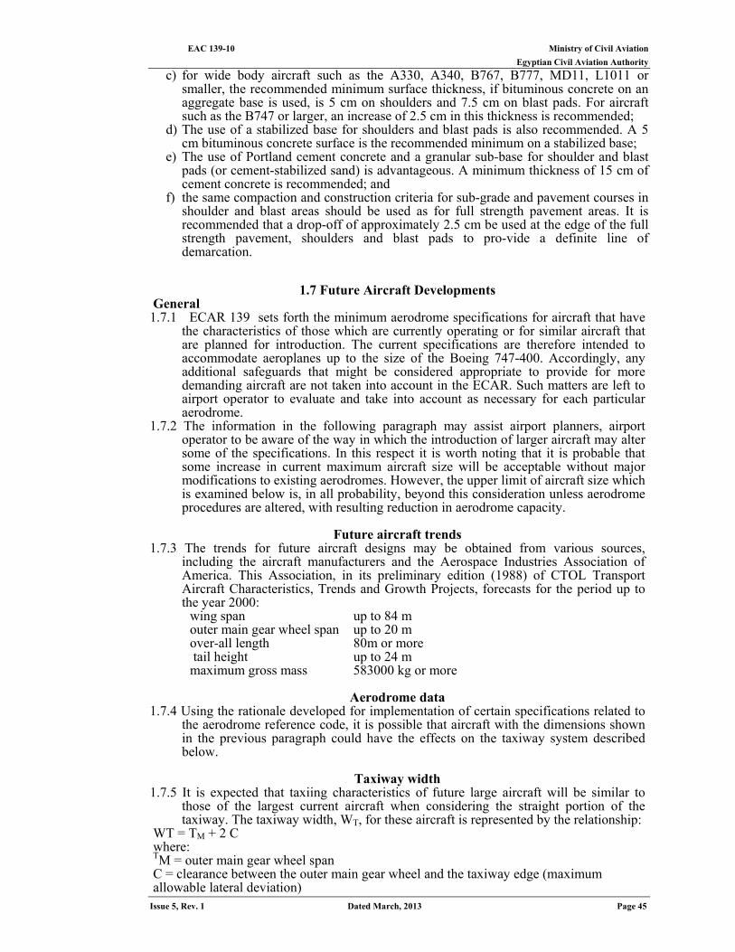
Ministry of Civil Aviation EAC 139-10 Egyptian Civil Aviation Authority
Issue 5, Rev. 1 Dated March, 2013 Page 45
c) for wide body aircraft such as the A330, A340, B767, B777, MD11, L1011 or smaller, the recommended minimum surface thickness, if bituminous concrete on an aggregate base is used, is 5 cm on shoulders and 7.5 cm on blast pads. For aircraft such as the B747 or larger, an increase of 2.5 cm in this thickness is recommended;
d) The use of a stabilized base for shoulders and blast pads is also recommended. A 5 cm bituminous concrete surface is the recommended minimum on a stabilized base;
e) The use of Portland cement concrete and a granular sub-base for shoulder and blast pads (or cement-stabilized sand) is advantageous. A minimum thickness of 15 cm of cement concrete is recommended; and
f) the same compaction and construction criteria for sub-grade and pavement courses in shoulder and blast areas should be used as for full strength pavement areas. It is recommended that a drop-off of approximately 2.5 cm be used at the edge of the full strength pavement, shoulders and blast pads to pro-vide a definite line of demarcation.
1.7 Future Aircraft Developments General 1.7.1 ECAR 139 sets forth the minimum aerodrome specifications for aircraft that have
the characteristics of those which are currently operating or for similar aircraft that are planned for introduction. The current specifications are therefore intended to accommodate aeroplanes up to the size of the Boeing 747-400. Accordingly, any additional safeguards that might be considered appropriate to provide for more demanding aircraft are not taken into account in the ECAR. Such matters are left to airport operator to evaluate and take into account as necessary for each particular aerodrome.
1.7.2 The information in the following paragraph may assist airport planners, airport operator to be aware of the way in which the introduction of larger aircraft may alter some of the specifications. In this respect it is worth noting that it is probable that some increase in current maximum aircraft size will be acceptable without major modifications to existing aerodromes. However, the upper limit of aircraft size which is examined below is, in all probability, beyond this consideration unless aerodrome procedures are altered, with resulting reduction in aerodrome capacity.
Future aircraft trends
1.7.3 The trends for future aircraft designs may be obtained from various sources, including the aircraft manufacturers and the Aerospace Industries Association of America. This Association, in its preliminary edition (1988) of CTOL Transport Aircraft Characteristics, Trends and Growth Projects, forecasts for the period up to the year 2000:
wing span up to 84 m outer main gear wheel span up to 20 m over-all length 80m or more tail height up to 24 m maximum gross mass 583000 kg or more
Aerodrome data
1.7.4 Using the rationale developed for implementation of certain specifications related to the aerodrome reference code, it is possible that aircraft with the dimensions shown in the previous paragraph could have the effects on the taxiway system described below.
Taxiway width
1.7.5 It is expected that taxiing characteristics of future large aircraft will be similar to those of the largest current aircraft when considering the straight portion of the taxiway. The taxiway width, WT, for these aircraft is represented by the relationship:
WT = TM + 2 C where: TM = outer main gear wheel span C = clearance between the outer main gear wheel and the taxiway edge (maximum allowable lateral deviation)
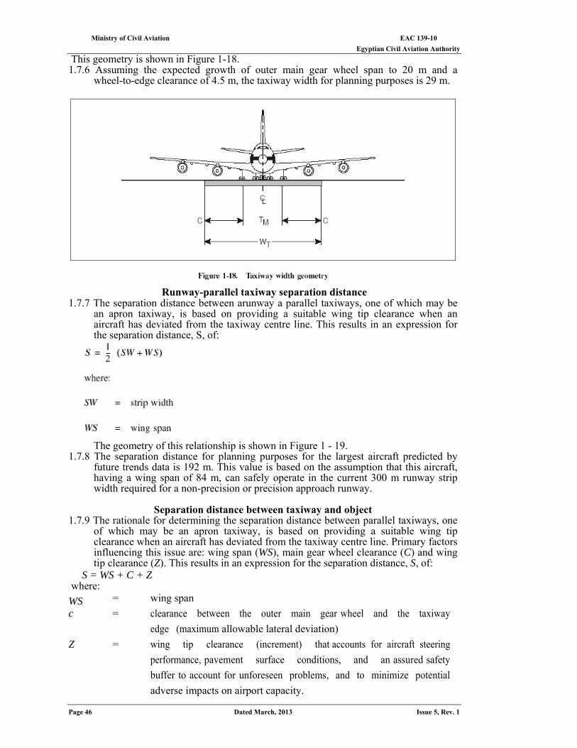
EAC 139-10 Ministry of Civil Aviation Egyptian Civil Aviation Authority
Page 46 Dated March, 2013 Issue 5, Rev. 1
This geometry is shown in Figure 1-18. 1.7.6 Assuming the expected growth of outer main gear wheel span to 20 m and a
wheel-to-edge clearance of 4.5 m, the taxiway width for planning purposes is 29 m.
Runway-parallel taxiway separation distance
1.7.7 The separation distance between arunway a parallel taxiways, one of which may be an apron taxiway, is based on providing a suitable wing tip clearance when an aircraft has deviated from the taxiway centre line. This results in an expression for the separation distance, S, of:
The geometry of this relationship is shown in Figure 1 - 19.
1.7.8 The separation distance for planning purposes for the largest aircraft predicted by future trends data is 192 m. This value is based on the assumption that this aircraft, having a wing span of 84 m, can safely operate in the current 300 m runway strip width required for a non-precision or precision approach runway.
Separation distance between taxiway and object
1.7.9 The rationale for determining the separation distance between parallel taxiways, one of which may be an apron taxiway, is based on providing a suitable wing tip clearance when an aircraft has deviated from the taxiway centre line. Primary factors influencing this issue are: wing span (WS), main gear wheel clearance (C) and wing tip clearance (Z). This results in an expression for the separation distance, S, of:
S = WS + C + Z where:
WS = wing span
c = clearance between the outer main gear wheel and the taxiway
edge (maximum allowable lateral deviation)
Z = wing tip clearance (increment) that accounts for aircraft steering
performance, pavement surface conditions, and an assured safety
buffer to account for unforeseen problems, and to minimize potential
adverse impacts on airport capacity.
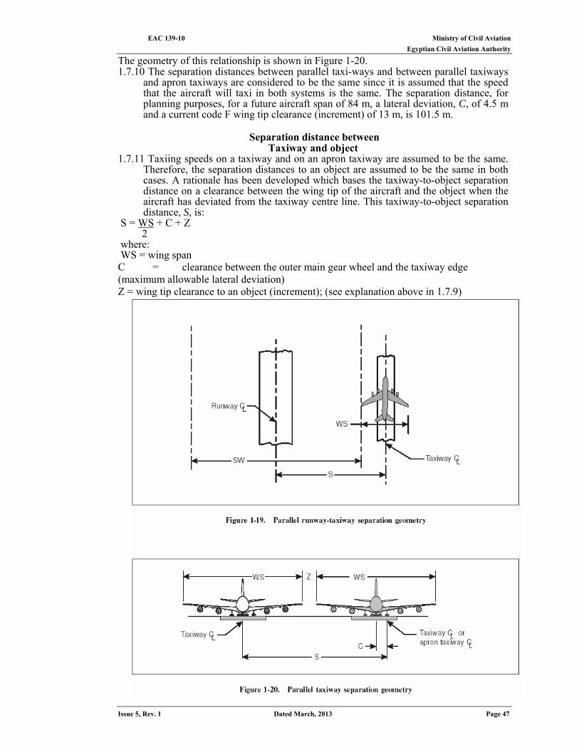
Ministry of Civil Aviation EAC 139-10 Egyptian Civil Aviation Authority
Issue 5, Rev. 1 Dated March, 2013 Page 47
The geometry of this relationship is shown in Figure 1-20. 1.7.10 The separation distances between parallel taxi-ways and between parallel taxiways
and apron taxiways are considered to be the same since it is assumed that the speed that the aircraft will taxi in both systems is the same. The separation distance, for planning purposes, for a future aircraft span of 84 m, a lateral deviation, C, of 4.5 m and a current code F wing tip clearance (increment) of 13 m, is 101.5 m.
Separation distance between
Taxiway and object 1.7.11 Taxiing speeds on a taxiway and on an apron taxiway are assumed to be the same.
Therefore, the separation distances to an object are assumed to be the same in both cases. A rationale has been developed which bases the taxiway-to-object separation distance on a clearance between the wing tip of the aircraft and the object when the aircraft has deviated from the taxiway centre line. This taxiway-to-object separation distance, S, is:
Z + C + WS= S 2 where:
WS = wing span C = clearance between the outer main gear wheel and the taxiway edge (maximum allowable lateral deviation) Z = wing tip clearance to an object (increment); (see explanation above in 1.7.9)
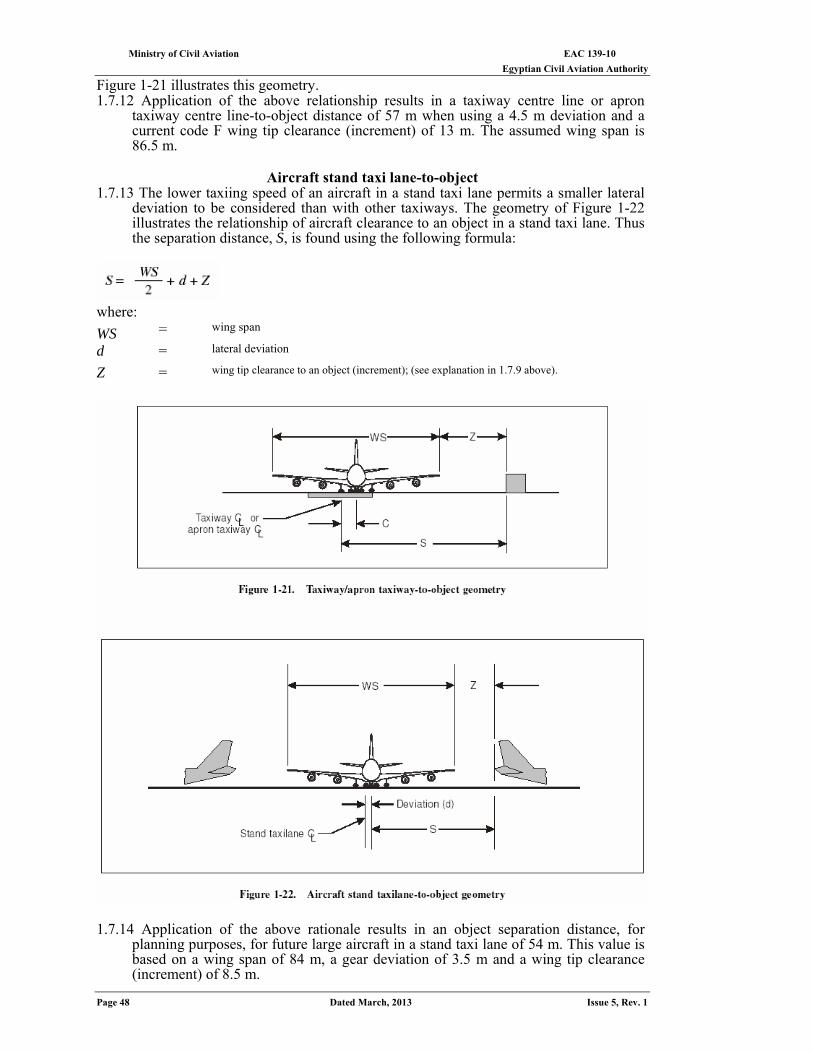
EAC 139-10 Ministry of Civil Aviation Egyptian Civil Aviation Authority
Page 48 Dated March, 2013 Issue 5, Rev. 1
Figure 1-21 illustrates this geometry. 1.7.12 Application of the above relationship results in a taxiway centre line or apron
taxiway centre line-to-object distance of 57 m when using a 4.5 m deviation and a current code F wing tip clearance (increment) of 13 m. The assumed wing span is 86.5 m.
Aircraft stand taxi lane-to-object
1.7.13 The lower taxiing speed of an aircraft in a stand taxi lane permits a smaller lateral deviation to be considered than with other taxiways. The geometry of Figure 1-22 illustrates the relationship of aircraft clearance to an object in a stand taxi lane. Thus the separation distance, S, is found using the following formula:
where:
WS = wing span
d = lateral deviation
Z = wing tip clearance to an object (increment); (see explanation in 1.7.9 above).
1.7.14 Application of the above rationale results in an object separation distance, for
planning purposes, for future large aircraft in a stand taxi lane of 54 m. This value is based on a wing span of 84 m, a gear deviation of 3.5 m and a wing tip clearance (increment) of 8.5 m.
Ministry of Civil Aviation EAC 139-10 Egyptian Civil Aviation Authority
Issue 5, Rev. 1 Dated March, 2013 Page 49
Other considerations 1.7.15 In addition to the guidance in the preceding paragraphs, preliminary criteria to
accommodate future aircraft development are described below: Runway Width : 60 M Runway sight distance: Same as current requirement for code letter E Runway transverse slope: Same as current requirement for code letter E Runway shoulders: Over-all width of runway and shoulder - 75 m. A widened area should be prepared to prevent erosion of the adjacent area and foreign object damage Slope and strength of runway shoulders: Same as current requirement for code letter E Minimum separation distances between taxiway / apron centre line and runway centre line:
1/2 wing span (Y) 42 m 1/2 strip width (non-instrument approach runway) 75 m Total 117 m or 1/2 wing span (Y) 42 m 1/2 strip width (instrument approach runway) 150 m Total 192 m
Taxiway pavement and shoulder (over-all width): Adequate space should be prepared to prevent erosion of the adjacent area and foreign
object damage. The width of that portion of a taxiway bridge capable of supporting aeroplanes shall not be less than the width of the graded area of the strip provided for that taxiway.
Graded portion of taxiway strip (over-all width): Adequate space should be prepared to prevent erosion of the adjacent area and foreign
object damage. The width of that portion of a taxiway bridge capable of supporting aeroplanes shall not be less than the width of the graded area of the strip provided for that taxiway.
EAC 139-10 Ministry of Civil Aviation Egyptian Civil Aviation Authority
Page 50 Dated March, 2013 Issue 5, Rev. 1
CHAPTER 2
Holding bays and Other bypasses
2.1 Need for Holding Bays and Other Bypasses 2.1.1 Procedures for Air Navigation Services —ECAR 172 — Departure Sequence, states
that “departures shall normally be cleared in the order in which they are ready for take-off, except that deviations may be made from this order of priority to facilitate the maximum number of departures with the least average delay”. At low levels of aerodrome activity (less than approximately 50 000 annual operations), there is normally little need to make deviations in the departure sequence. However, for higher activity levels, aerodromes with single taxiways and no holding bays or other bypasses provide aerodrome control units with no opportunity to change the sequence of departures once the aircraft have left the apron, In particular, at aerodromes with large apron areas, it is often difficult to arrange for aircraft to leave the apron in such a way that they will arrive at the end of the runway in the sequence required by air traffic services units.
2.1.2 The provision of an adequate number of holding bay spaces or other bypasses, based upon an analysis of the current and near-term hourly aircraft departure demand, will allow a large degree of flexibility in generating the departure sequence. This provides air traffic services units with greater flexibility in adjusting the take-off sequence to overcome undue delays, thus increasing the capacity of an aerodrome. In addition, holding bays or other bypasses allow:
(a) departure of certain aircraft to be delayed owing to unforeseen circumstances without delaying the following aircraft (for instance, a last minute addition to the payload or a replacement of defective equipment);
(b) aircraft to carry out pre-flight altimeter checks and alignment and programming of airborne inertial navigation systems when this is not possible on the apron;
(c) engine rumpus for piston aircraft; and (d) establishment of a VOR aerodrome check-point.
2.2 TYPES OF BYPASSES
2.2.1 In general, taxiway features that allow an aircraft to bypass a preceding aircraft can be divided into three types:
(a) Holding bays. A defined area where aircraft can be held or bypassed. Figure 2-1 shows some examples of holding bay configurations and Figure 2-2 gives a detailed example of a holding bay, located at the taxi-holding position.
(b) Dual taxiways. A second taxiway or a taxiway bypass to the normal parallel taxiway. Figure 2-3 shows some examples.
(c) Dual runway entrances. A duplication of the taxiway entrance to the runway. Some examples are shown in Figure 2-4.
2.2.2 If a holding bay is used, aircraft can, on the basis of their priority, take off in any order. The availability of a holding bay allows aircraft to leave and independently re-enter the departure stream.
A detailed example of the pavement area for a holding bay located at the taxi-holding position is shown in Figure 2-2. This design is for a non-precision or a precision approach runway where the code number is 3 or 4 and incorporates an aircraft wing-tip-to-wing-tip clearance of 15 m when both aircraft are centered on the centre line. Holding bay design for other runway types or locations along the taxiway will have proportional dimensional requirements. 2.2.3 Dual taxiways or taxiway bypasses can only achieve relative departure priority by
separating the departure stream into two parts. Taxi bypasses can be constructed at a relatively low cost, but provide only a small amount of flexibility to alter the departure sequence. A full length dual taxiway is the most expensive alternative and can only be justified at very high activity aerodromes where there is a clear need for two-directional movement parallel to the runway. This need arises when the land alongside the taxiway is developed into passenger terminal aprons or other facilities that generate aircraft movements opposite to the departure flow.
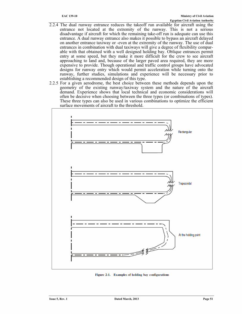
Ministry of Civil Aviation EAC 139-10 Egyptian Civil Aviation Authority
Issue 5, Rev. 1 Dated March, 2013 Page 51
2.2.4 The dual runway entrance reduces the takeoff run available for aircraft using the entrance not located at the extremity of the runway. This is not a serious disadvantage if aircraft for which the remaining take-off run is adequate can use this entrance. A dual runway entrance also makes it possible to bypass an aircraft delayed on another entrance taxiway or -even at the extremity of the runway. The use of dual entrances in combination with dual taxiways will give a degree of flexibility compar-able with that obtained with a well designed holding bay. Oblique entrances permit entry at some speed, but they make it more difficult for the crew to see aircraft approaching to land and, because of the larger paved area required, they are more expensive to provide. Though operational and traffic control groups have advocated designs for runway entry which would permit acceleration while turning onto the runway, further studies, simulations and experience will be necessary prior to establishing a recommended design of this type.
2.2.5 For a given aerodrome, the best choice between these methods depends upon the geometry of the existing runway/taxiway system and the nature of the aircraft demand. Experience shows that local technical and economic considerations will often be decisive when choosing between the three types (or combinations of types). These three types can also be used in various combinations to optimize the efficient surface movements of aircraft to the threshold.
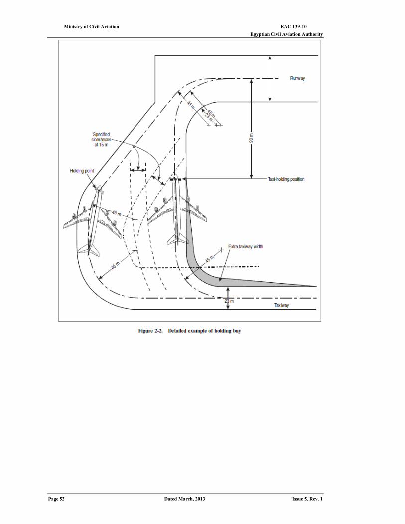
EAC 139-10 Ministry of Civil Aviation Egyptian Civil Aviation Authority
Page 52 Dated March, 2013 Issue 5, Rev. 1
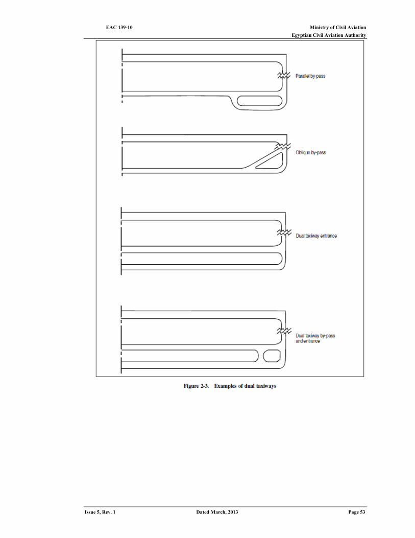
Ministry of Civil Aviation EAC 139-10 Egyptian Civil Aviation Authority
Issue 5, Rev. 1 Dated March, 2013 Page 53
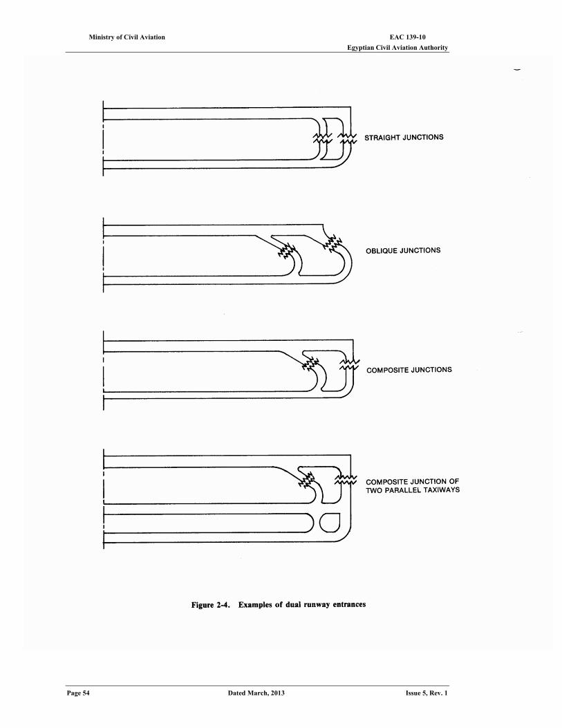
EAC 139-10 Ministry of Civil Aviation Egyptian Civil Aviation Authority
Page 54 Dated March, 2013 Issue 5, Rev. 1
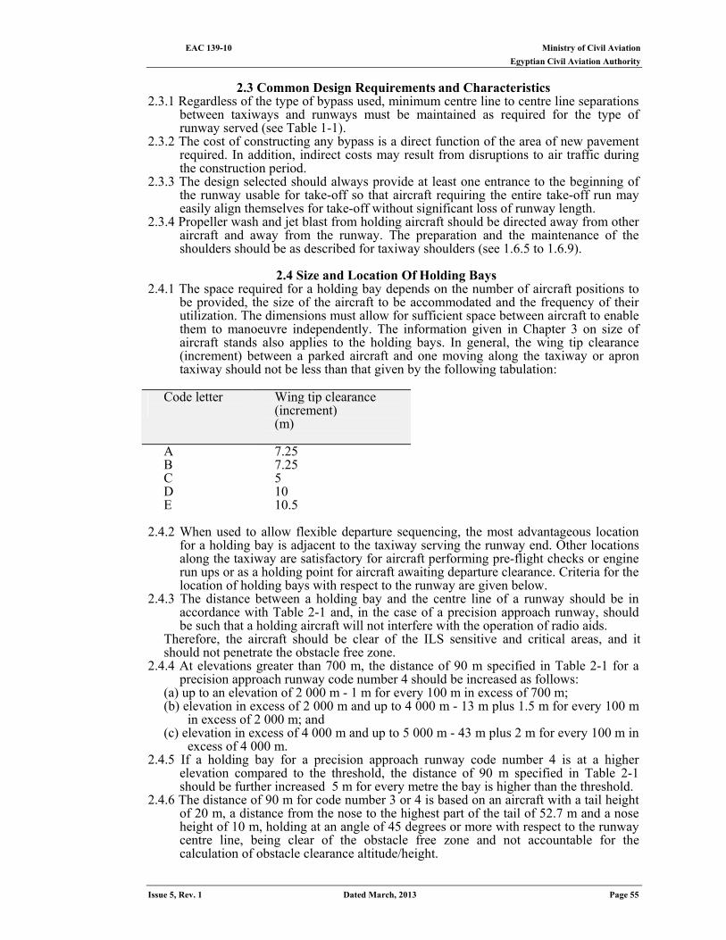
Ministry of Civil Aviation EAC 139-10 Egyptian Civil Aviation Authority
Issue 5, Rev. 1 Dated March, 2013 Page 55
2.3 Common Design Requirements and Characteristics
2.3.1 Regardless of the type of bypass used, minimum centre line to centre line separations between taxiways and runways must be maintained as required for the type of runway served (see Table 1-1).
2.3.2 The cost of constructing any bypass is a direct function of the area of new pavement required. In addition, indirect costs may result from disruptions to air traffic during the construction period.
2.3.3 The design selected should always provide at least one entrance to the beginning of the runway usable for take-off so that aircraft requiring the entire take-off run may easily align themselves for take-off without significant loss of runway length.
2.3.4 Propeller wash and jet blast from holding aircraft should be directed away from other aircraft and away from the runway. The preparation and the maintenance of the shoulders should be as described for taxiway shoulders (see 1.6.5 to 1.6.9).
2.4 Size and Location Of Holding Bays
2.4.1 The space required for a holding bay depends on the number of aircraft positions to be provided, the size of the aircraft to be accommodated and the frequency of their utilization. The dimensions must allow for sufficient space between aircraft to enable them to manoeuvre independently. The information given in Chapter 3 on size of aircraft stands also applies to the holding bays. In general, the wing tip clearance (increment) between a parked aircraft and one moving along the taxiway or apron taxiway should not be less than that given by the following tabulation:
Code letter
Wing tip clearance (increment) (m)
A 7.25 B 7.25 C 5 D 10 E 10.5
2.4.2 When used to allow flexible departure sequencing, the most advantageous location
for a holding bay is adjacent to the taxiway serving the runway end. Other locations along the taxiway are satisfactory for aircraft performing pre-flight checks or engine run ups or as a holding point for aircraft awaiting departure clearance. Criteria for the location of holding bays with respect to the runway are given below.
2.4.3 The distance between a holding bay and the centre line of a runway should be in accordance with Table 2-1 and, in the case of a precision approach runway, should be such that a holding aircraft will not interfere with the operation of radio aids.
Therefore, the aircraft should be clear of the ILS sensitive and critical areas, and it should not penetrate the obstacle free zone.
2.4.4 At elevations greater than 700 m, the distance of 90 m specified in Table 2-1 for a precision approach runway code number 4 should be increased as follows:
(a) up to an elevation of 2 000 m - 1 m for every 100 m in excess of 700 m; (b) elevation in excess of 2 000 m and up to 4 000 m - 13 m plus 1.5 m for every 100 m
in excess of 2 000 m; and (c) elevation in excess of 4 000 m and up to 5 000 m - 43 m plus 2 m for every 100 m in
excess of 4 000 m. 2.4.5 If a holding bay for a precision approach runway code number 4 is at a higher
elevation compared to the threshold, the distance of 90 m specified in Table 2-1 should be further increased 5 m for every metre the bay is higher than the threshold.
2.4.6 The distance of 90 m for code number 3 or 4 is based on an aircraft with a tail height of 20 m, a distance from the nose to the highest part of the tail of 52.7 m and a nose height of 10 m, holding at an angle of 45 degrees or more with respect to the runway centre line, being clear of the obstacle free zone and not accountable for the calculation of obstacle clearance altitude/height.
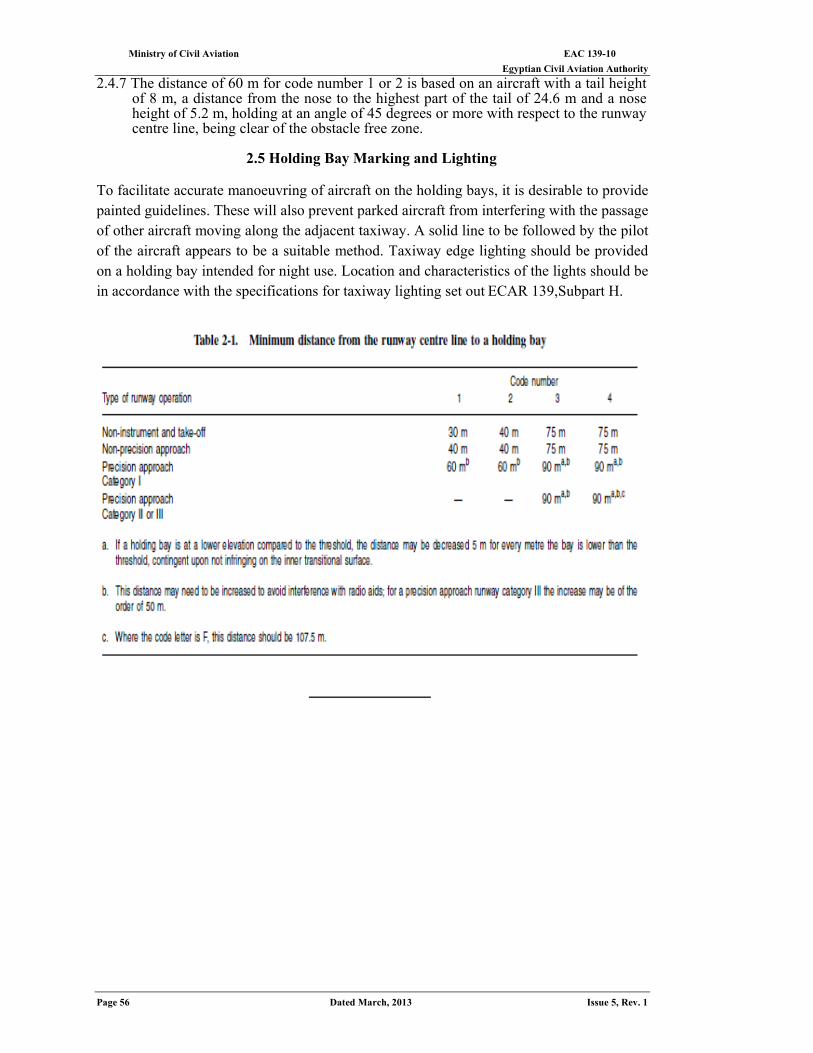
EAC 139-10 Ministry of Civil Aviation Egyptian Civil Aviation Authority
Page 56 Dated March, 2013 Issue 5, Rev. 1
2.4.7 The distance of 60 m for code number 1 or 2 is based on an aircraft with a tail height of 8 m, a distance from the nose to the highest part of the tail of 24.6 m and a nose height of 5.2 m, holding at an angle of 45 degrees or more with respect to the runway centre line, being clear of the obstacle free zone.
2.5 Holding Bay Marking and Lighting
To facilitate accurate manoeuvring of aircraft on the holding bays, it is desirable to provide painted guidelines. These will also prevent parked aircraft from interfering with the passage of other aircraft moving along the adjacent taxiway. A solid line to be followed by the pilot of the aircraft appears to be a suitable method. Taxiway edge lighting should be provided on a holding bay intended for night use. Location and characteristics of the lights should be in accordance with the specifications for taxiway lighting set out ECAR 139,Subpart H.
Ministry of Civil Aviation EAC 139-10 Egyptian Civil Aviation Authority
Issue 5, Rev. 1 Dated March, 2013 Page 57
CHAPTER 3
Aprons
An apron is a defined area intended to accommodate aircraft for purposes of loading and unloading passengers, mail or cargo, fuelling and parking or maintenance. The apron is generally paved but may occasionally be unpaved; for example, in some instances, a turf parking apron may be adequate for small aircraft.
3.1 Types Of Aprons
Passenger terminal apron 3.1.1 The passenger terminal apron is an area designed for aircraft manoeuvring and
parking that is adjacent or readily accessible to passenger terminal facilities. This area is where passengers board the aircraft from the passenger terminal. In addition to facilitating passenger movement, the passenger terminal apron is used for aircraft fuelling and maintenance as well as loading and unloading cargo, mail and baggage. Individual aircraft parking positions on the passenger terminal apron are referred to as aircraft stands.
Cargo terminal apron 3.1.2 Aircraft that carry only freight and mail may be provided a separate cargo terminal
apron adjacent to a cargo terminal building. The separation of cargo and passenger aircraft is desirable because of the different types of facilities each requires both on the apron and at the terminal.
Parking apron 3.1.3 In addition to the terminal apron, airports may require a separate parking apron where
aircraft can park for extended periods. These aprons can be used during crew layovers or for light periodic servicing and maintenance of temporarily grounded aircraft. While parking aprons are removed from the terminal aprons, they should be located as close to them as is practical.
Service and hangar aprons 3.1.4 A service apron is an uncovered area adjacent to a repair hangar on which aircraft
maintenance can be performed, while a hangar apron is an area on which aircraft move into and out of a storage hangar.
General aviation aprons 3.1.5 General aviation aircraft, used for business or personal flying, require several
categories of aprons to support different general aviation activities. Itinerant apron. 3.1.5.1 Itinerant (transient) general aviation aircraft use the itinerant apron as temporary
aircraft parking facilities and as access to fuelling, servicing and ground transportation. At aerodromes servicing only general aviation aircraft, the itinerant apron is usually adjacent to, or an integral part of, a fixed-based operator's area. The terminal apron will generally also set aside some area for itinerant general aviation aircraft.
Base aircraft aprons or tied owns 3.1.5.2 General aviation aircraft based at an aerodrome require either hangar storage or a
tie down space in the open. Hungered aircraft also need an apron in front of the building for maneuvering. Open areas used for base aircraft tiedown may be paved, unpaved or turf, depending on the size of aircraft and local weather and soil conditions. It is desirable that they be in a separate location from the itinerant aircraft aprons.
Other ground servicing aprons 3.1.5.3 Areas for servicing, fuelling or loading and unloading should also be provided as
needed.
3.2 Design Requirements 3.2.1 The design of any of the various apron types requires the evaluation of many
interrelated and often contradictory characteristics. Despite the distinct purposes of
EAC 139-10 Ministry of Civil Aviation Egyptian Civil Aviation Authority
Page 58 Dated March, 2013 Issue 5, Rev. 1
the different apron types, there are many general design characteristics relating to safety, efficiency, geometry, flexibility and engineering that are common to all types. The following paragraphs give a brief description of these general design requirements.
Safety 3.2.2 Apron design should take into account safety procedures for aircraft manoeuvring on
the apron. Safety in this context implies that aircraft maintain specified clearances and follow the established procedures to enter, move within and depart from apron areas. Provision of services to aircraft parked on the apron should also incorporate safety procedures, especially regarding aircraft fuelling. Pavements should slope away from terminal buildings and other structures to prevent the spread of fuel fires on the apron. Water outlets should be located at each stand position for routine hosing of the apron surface. Aircraft security should also be considered in locating the apron area where the aircraft can be protected from unauthorized personnel. This is accomplished by physically separating public access areas from the apron areas.
Efficiency 3.2.3 Apron design should contribute towards establishing a high degree of efficiency for
aircraft movements and dispensing apron services. Freedom of movement, minimum taxi distances and a minimum of delay for aircraft initiating movements on the apron are all measures of efficiency for any of the apron types. If the ultimate aircraft stand arrangement can be determined during the initial planning phase of the aerodrome, then utilities and services should be installed in fixed installations. Fuel lines and hydrants, compressed air hook-ups and electrical power systems must be carefully preplanned because these systems are often placed under the apron pavement. The high initial cost of these systems will be offset by the increased efficiency of the stand, which allows greater utilization of the apron. Achieving these measures of efficiency will ensure the maximum economic value of the apron.
Geometry 3.2.4 The planning and design of any apron type are dependent upon a number of
geometric considerations. For example, the length and width of a land parcel available for apron development may preclude the choice of certain apron layout concepts. For a new aerodrome it may be possible to develop the most efficient arrangement, based upon the nature of the demand, and then to set aside an area of land ideally suited to the concept. However, expansion or addition of aprons at existing aerodromes will usually be less than ideal as a result of the limitations imposed by the shape and size of available parcels. The over-all area needed per aircraft stand includes the area required for aircraft stand taxi lanes as well as apron taxiways used in common with other aircraft stands. Therefore, the over-all area needed for apron development is a function not only of aircraft size, clearances and parking method, but also of the geometric arrangement of aircraft stand taxi lanes, other taxiways, blast fences, areas used for the stationing of service vehicles and roads for the movement of ground vehicles.
Flexibility 3.2.5 Planning for aprons should include an evaluation of the following flexibility
characteristics. Range of aircraft sizes
3.2.5.1 The number and size of aircraft stands should be matched to the number and size of aircraft types expected to use the apron. A compromise must be developed between the extremes of:
(a) using one size of aircraft stand large enough for the largest aircraft type; and (b) using as many different sized stands as there are aircraft types. The first method is a highly inefficient use of area, while the second provides a low level of operating flexibility. For passenger terminal aprons, a compromise solution that achieves adequate flexibility is to group the aircraft into twoo to four size classes and provide stands for a mix of these general sizes in proportion to the demand forecast. A greater number of general aviation parking space sizes can be used because the space may be leased and occupied by a single aircraft of known dimensions.
Expansion capability 3.2.5.2 Another key element of a flexible apron system is allowance for expansion to
meet future needs. To avoid undue restriction of the growth potential of a particular
Ministry of Civil Aviation EAC 139-10 Egyptian Civil Aviation Authority
Issue 5, Rev. 1 Dated March, 2013 Page 59
apron area, the apron should be designed in modular stages so that successive stages become integral additions to the existing apron with a minimum of disruption to ongoing activities.
Common design characteristics 3.2.6 Many technical design requirements for the construction of apron surfaces are
common to all apron types. Several of these factors are described in the following paragraphs.
Pavement 3.2.6.1 The choice of pavement surface is a function of aircraft mass, load distribution,
soil conditions and the relative cost of alternative materials. Reinforced concrete is routinely used at aerodromes serving the largest commercial aircraft where greater strength and durability are needed. As a minimum, most aerodromes require an asphalt (tarmac) surface to satisfy strength, drainage and stabilization criteria, though turf and cement-stabilized sand aprons have been satisfactorily used in some locations. Reinforced concrete is usually more expensive to install than asphalt but is less expensive to maintain and usually lasts longer. In addition, concrete is relatively unaffected by spilled jet fuel, whereas asphalt surfaces are damaged if fuel remains on the surface for even short periods of time. This problem can be partially overcome by coating the asphalt with special sealants and by frequently washing off the pavement.
Pavement slope 3.2.6.2 Slopes on an apron should be sufficient to prevent accumulation of water on the
surface of the apron but should be kept as level as drainage requirements permit. Efficient storm drainage of large, paved apron areas is normally achieved by providing a steep pavement slope and numerous area drains. On aprons, however, too great a slope will create manoeuvrability problems for aircraft and service vehicles operating on the apron. Additionally, fuelling of aircraft requires nearly a level surface to achieve the proper fuel mass balance in the assorted aircraft storage tanks. The design of slopes and drains should direct spilled fuel away from building and apron service areas. In order to accommodate the needs for drainage, manoeuvrability and fuelling, apron slopes should be 0.5 to 1.0 per cent in the aircraft stand areas and no more than 1.5 per cent in the other apron areas.
Jet blast and propeller wash 3.2.6.3 The effects of extreme heat and air velocities from jet and propeller engines must
be considered when planning apron areas and adjacent service roads and buildings. For some aerodromes, it may be necessary to provide greater aircraft-to-aircraft separations or erect blast fences between parking spaces to counteract these effects. Appendix 2 gives greater detail on this design consideration.
3.3 Basic Terminal Apron Layouts
General considerations 3.3.1 The type of terminal apron parking layout best suited to a particular aerodrome is a
function of many interrelated criteria. Design of the terminal apron must, of course, be completely consistent with the choice of terminal design and vice versa. An iterative procedure for selecting the best combination of apron and terminal design should be used to compare the advantages and disadvantages of each system analyzed separately. The volume of aircraft traffic using the terminal is an important factor in determining the apron layout that is most efficient in serving a particular terminal design. In addition, an aerodrome with a disproportionate percentage of international transfer (direct connation with another flight) or locally originating passengers may need a specialized terminal and apron system design to accommodate the skewed characteristic of the passenger traffic.
Passenger loading 3.3.2 The passenger loading method to be used must be taken into account when planning
the apron layout. Some methods can be used with only one or two of the basic parking layouts.
3.3.2.1 Direct upper level loading is made possible by the development of the loading bridge, permitting the passenger to board the aircraft from the upper level of the terminal building. Two types of aircraft loading bridges are illustrated in Figure 3-1:
EAC 139-10 Ministry of Civil Aviation Egyptian Civil Aviation Authority
Page 60 Dated March, 2013 Issue 5, Rev. 1
(a) The stationary loading bridge. A short loading bridge which extends from a projection in the building. The aircraft parks nose-in alongside the projection and stops with the aircraft front door opposite the bridge. The bridge extends a very short distance to the aircraft, allowing very little variation between the height of the aircraft main deck and the terminal floor.
(b) The apron drive loading bridge. A bridge which has one end of a telescoping gangway hinged to the terminal building and the other end supported by a steerable, powered dual-wheel. The bridge pivots towards the aircraft and lengthens until it reaches the aircraft door. The end mating with the aircraft can be raised or lowered significantly, permitting aircraft of varying deck heights to be served from the loading bridge.
3.3.2.2 There are other basic passenger loading methods used in addition to aircraft loading bridges:
(a) Movable steps. Movable steps are pushed or driven to the aircraft and set at door level. Passengers walk in the open on the apron or are driven by bus between the terminal and the aircraft and use the steps to board the aircraft.
(b) Passenger transports. Passengers board a bus or specially designed passenger transporter at the terminal building and are driven to a remote aircraft stand. Passengers then may use steps to board the aircraft or board the aircraft from the same level as the aircraft floor, i.e. by elevation of the vehicle.
(c) Aircraft-contained steps. This procedure is similar to the movable steps and can be used with any aircraft equipped with self-contained steps. After stopping, the crew releases the self-contained steps and passengers walk on the apron or are driven by bus between the aircraft and the terminal building.
Passenger terminal apron concepts
3.3.3 The design of passenger terminal aprons is directly interrelated with the passenger terminal concept. Determination of passenger terminal concepts is described in the EAC 139-15 — Master Planning .Various apron/terminal concepts are illustrated in Figure 3-2 and the characteristics of each concept from the viewpoint of the apron are briefly described below.
Simple concept 3.3.4 This concept is to be applied at low traffic volume airports. Aircraft are normally
parked angled either nose-in or nose-out for self-taxi in and taxi out. Consideration should be given to providing adequate clearance between apron edge and air-side terminal frontage to reduce the adverse effects of jet engine blast. Where this is not done, jet engine blast fences should be provided. Apron expansion can be done incrementally in accordance with demands, causing little disruption of airport operation.
Linear concept 3.3.5 This concept may be regarded as one of the advanced stages of the simple concept.
Aircraft can be parked in an angled or parallel parking configuration. However, nose-in/push-out parking configuration with minimum clearance between apron edge and terminal is more common in this concept because of more efficient utilization of apron space and handling of aircraft and passengers. Nose-in parking affords relatively easy and simple manoeuvring for aircraft taxiing in to gate position. Push-out operations cause little disruption of apron activities in neighbouring gate positions. However, towing tractors and skilled operators are required. At busy traffic airports, it may become necessary to provide double apron taxiways to lessen the blocking of the taxiway by push-out operations. The corridor between the apron edge and terminal frontage can be used for circulation of apron traffic and the area around the nose of the parked aircraft can be used for ground service equipment parking slots. When apron depth is planned from the outset to cater to the longest fuselage length, the linear concept has as much flexibility and expansibility as the simple concept and almost as much as the open apron concept.
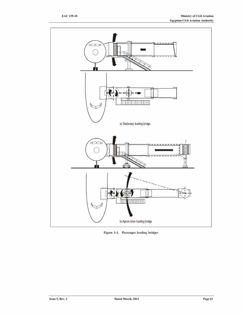
Ministry of Civil Aviation EAC 139-10 Egyptian Civil Aviation Authority
Issue 5, Rev. 1 Dated March, 2013 Page 61
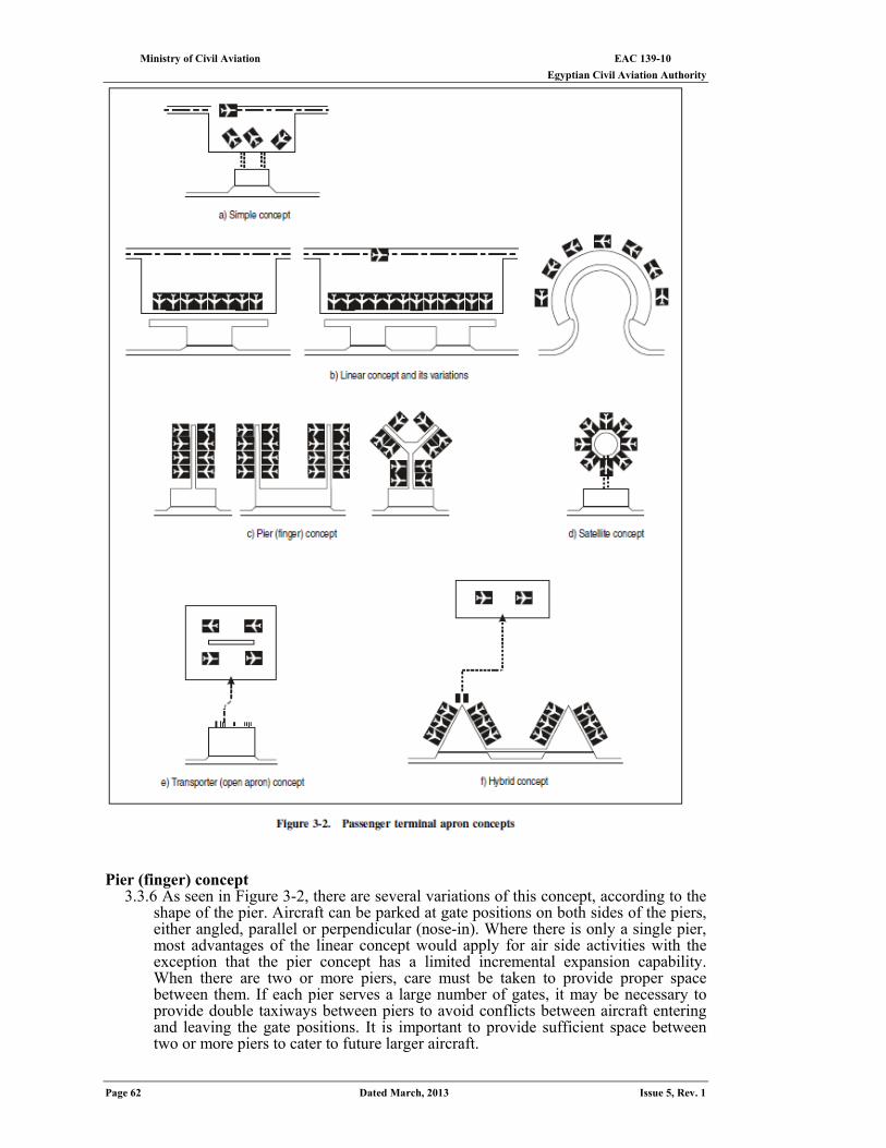
EAC 139-10 Ministry of Civil Aviation Egyptian Civil Aviation Authority
Page 62 Dated March, 2013 Issue 5, Rev. 1
Pier (finger) concept
3.3.6 As seen in Figure 3-2, there are several variations of this concept, according to the shape of the pier. Aircraft can be parked at gate positions on both sides of the piers, either angled, parallel or perpendicular (nose-in). Where there is only a single pier, most advantages of the linear concept would apply for air side activities with the exception that the pier concept has a limited incremental expansion capability. When there are two or more piers, care must be taken to provide proper space between them. If each pier serves a large number of gates, it may be necessary to provide double taxiways between piers to avoid conflicts between aircraft entering and leaving the gate positions. It is important to provide sufficient space between two or more piers to cater to future larger aircraft.
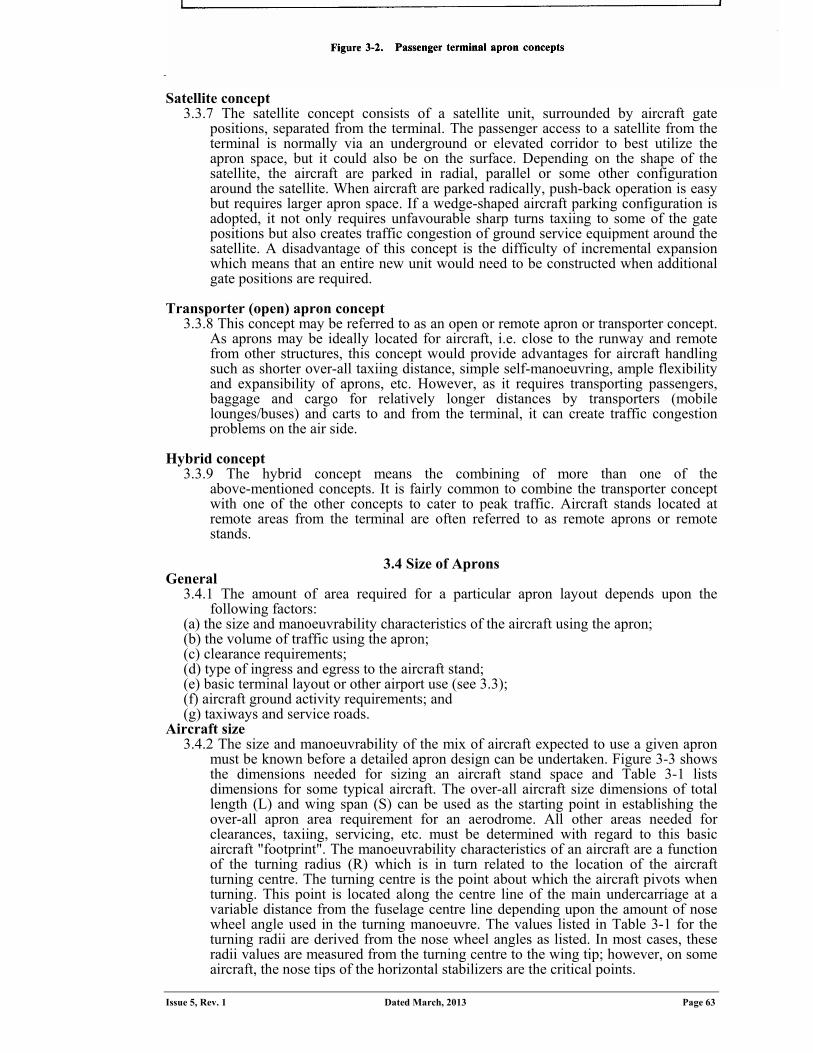
Ministry of Civil Aviation EAC 139-10 Egyptian Civil Aviation Authority
Issue 5, Rev. 1 Dated March, 2013 Page 63
Satellite concept 3.3.7 The satellite concept consists of a satellite unit, surrounded by aircraft gate
positions, separated from the terminal. The passenger access to a satellite from the terminal is normally via an underground or elevated corridor to best utilize the apron space, but it could also be on the surface. Depending on the shape of the satellite, the aircraft are parked in radial, parallel or some other configuration around the satellite. When aircraft are parked radically, push-back operation is easy but requires larger apron space. If a wedge-shaped aircraft parking configuration is adopted, it not only requires unfavourable sharp turns taxiing to some of the gate positions but also creates traffic congestion of ground service equipment around the satellite. A disadvantage of this concept is the difficulty of incremental expansion which means that an entire new unit would need to be constructed when additional gate positions are required.
Transporter (open) apron concept
3.3.8 This concept may be referred to as an open or remote apron or transporter concept. As aprons may be ideally located for aircraft, i.e. close to the runway and remote from other structures, this concept would provide advantages for aircraft handling such as shorter over-all taxiing distance, simple self-manoeuvring, ample flexibility and expansibility of aprons, etc. However, as it requires transporting passengers, baggage and cargo for relatively longer distances by transporters (mobile lounges/buses) and carts to and from the terminal, it can create traffic congestion problems on the air side.
Hybrid concept
3.3.9 The hybrid concept means the combining of more than one of the above-mentioned concepts. It is fairly common to combine the transporter concept with one of the other concepts to cater to peak traffic. Aircraft stands located at remote areas from the terminal are often referred to as remote aprons or remote stands.
3.4 Size of Aprons
General 3.4.1 The amount of area required for a particular apron layout depends upon the
following factors: (a) the size and manoeuvrability characteristics of the aircraft using the apron; (b) the volume of traffic using the apron; (c) clearance requirements; (d) type of ingress and egress to the aircraft stand; (e) basic terminal layout or other airport use (see 3.3); (f) aircraft ground activity requirements; and (g) taxiways and service roads.
Aircraft size 3.4.2 The size and manoeuvrability of the mix of aircraft expected to use a given apron
must be known before a detailed apron design can be undertaken. Figure 3-3 shows the dimensions needed for sizing an aircraft stand space and Table 3-1 lists dimensions for some typical aircraft. The over-all aircraft size dimensions of total length (L) and wing span (S) can be used as the starting point in establishing the over-all apron area requirement for an aerodrome. All other areas needed for clearances, taxiing, servicing, etc. must be determined with regard to this basic aircraft "footprint". The manoeuvrability characteristics of an aircraft are a function of the turning radius (R) which is in turn related to the location of the aircraft turning centre. The turning centre is the point about which the aircraft pivots when turning. This point is located along the centre line of the main undercarriage at a variable distance from the fuselage centre line depending upon the amount of nose wheel angle used in the turning manoeuvre. The values listed in Table 3-1 for the turning radii are derived from the nose wheel angles as listed. In most cases, these radii values are measured from the turning centre to the wing tip; however, on some aircraft, the nose tips of the horizontal stabilizers are the critical points.
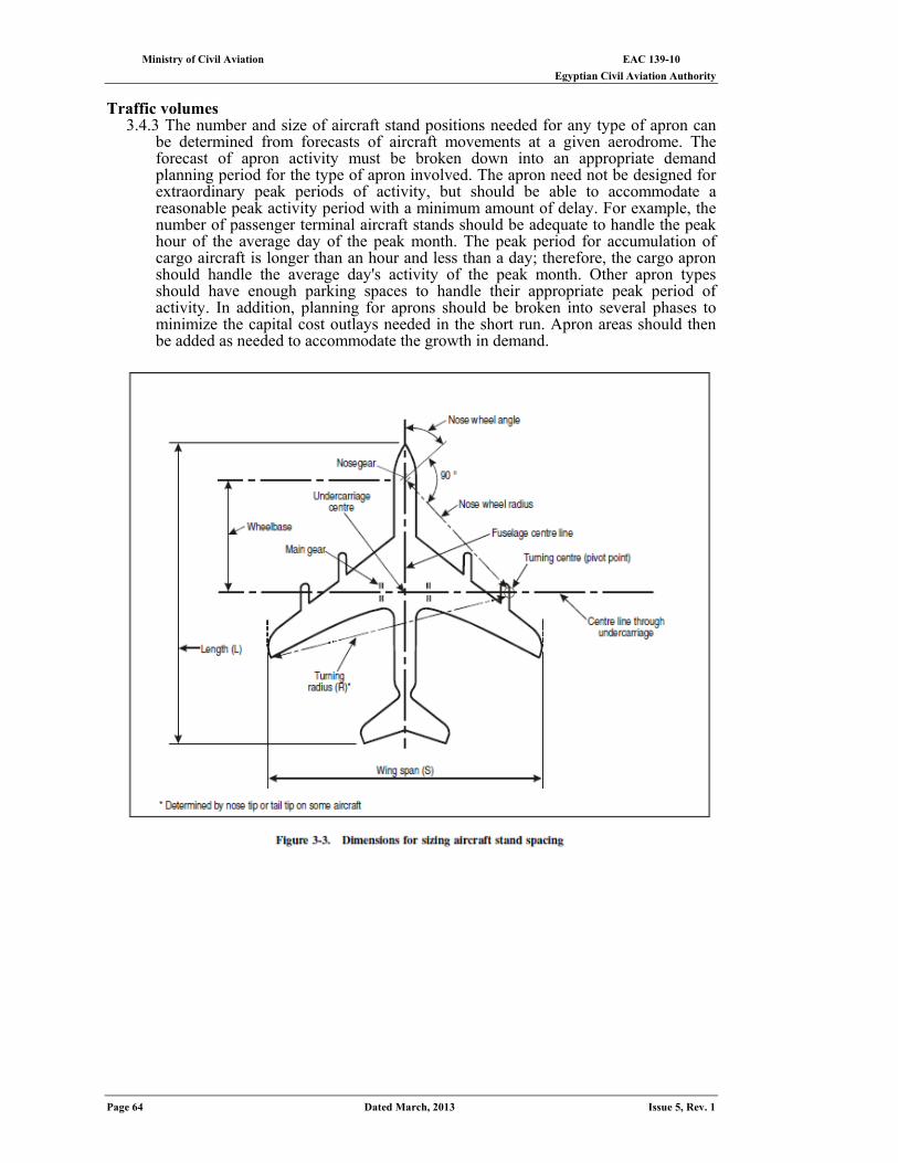
EAC 139-10 Ministry of Civil Aviation Egyptian Civil Aviation Authority
Page 64 Dated March, 2013 Issue 5, Rev. 1
Traffic volumes
3.4.3 The number and size of aircraft stand positions needed for any type of apron can be determined from forecasts of aircraft movements at a given aerodrome. The forecast of apron activity must be broken down into an appropriate demand planning period for the type of apron involved. The apron need not be designed for extraordinary peak periods of activity, but should be able to accommodate a reasonable peak activity period with a minimum amount of delay. For example, the number of passenger terminal aircraft stands should be adequate to handle the peak hour of the average day of the peak month. The peak period for accumulation of cargo aircraft is longer than an hour and less than a day; therefore, the cargo apron should handle the average day's activity of the peak month. Other apron types should have enough parking spaces to handle their appropriate peak period of activity. In addition, planning for aprons should be broken into several phases to minimize the capital cost outlays needed in the short run. Apron areas should then be added as needed to accommodate the growth in demand.
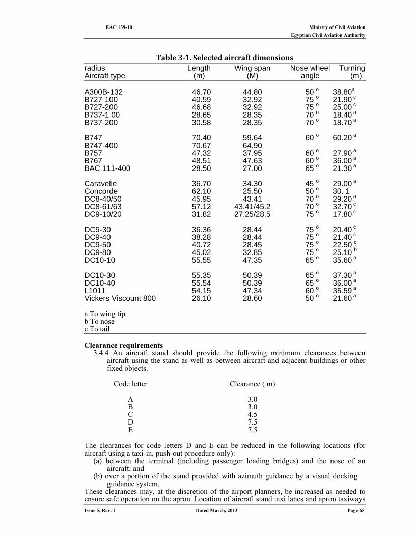
Ministry of Civil Aviation EAC 139-10 Egyptian Civil Aviation Authority
Issue 5, Rev. 1 Dated March, 2013 Page 65
Table 3‐1. Selected aircraft dimensions
radius Length Wing span Nose wheel Turning Aircraft type (m) (M) angle (m) A300B-132 46.70 44.80 50 o 38.80a B727-100 40.59 32.92 75 o 21.90 c B727-200 46.68 32.92 75 o 25.00 c B737-1 00 28.65 28.35 70 o 18.40 a B737-200 30.58 28.35 70 o 18.70 a B747 70.40 59.64 60 o 60.20 a B747-400 70.67 64.90 B757 47.32 37.95 60 o 27.90 a B767 48.51 47.63 60 o 36.00 a BAC 111-400 28.50 27.00 65 o 21.30 a Caravelle 36.70 34.30 45 o 29.00 a Concorde 62.10 25.50 50 o 30. 1 DC8-40/50 45.95 43.41 70 o 29.20 a DC8-61/63 57.12 43.41/45.2 70 o 32.70 c DC9-10/20 31.82 27.25/28.5 75 o 17.80 c DC9-30 36.36 28.44 75 o 20.40 c DC9-40 38.28 28.44 75 o 21.40 c DC9-50 40.72 28.45 75 o 22.50 c DC9-80 45.02 32.85 75 o 25.10 b DC10-10 55.55 47.35 65 o 35.60 a DC10-30 55.35 50.39 65 o 37.30 a DC10-40 55.54 50.39 65 o 36.00 a L1011 54.15 47.34 60 o 35.59 a Vickers Viscount 800 26.10 28.60 50 o 21.60 a
a To wing tip b To nose c To tail Clearance requirements
3.4.4 An aircraft stand should provide the following minimum clearances between aircraft using the stand as well as between aircraft and adjacent buildings or other fixed objects.
Code letter
Clearance ( m)
A 3.0 B 3.0 C 4.5 D 7.5 E 7.5
The clearances for code letters D and E can be reduced in the following locations (for aircraft using a taxi-in, push-out procedure only):
(a) between the terminal (including passenger loading bridges) and the nose of an aircraft; and
(b) over a portion of the stand provided with azimuth guidance by a visual docking guidance system.
These clearances may, at the discretion of the airport planners, be increased as needed to ensure safe operation on the apron. Location of aircraft stand taxi lanes and apron taxiways
EAC 139-10 Ministry of Civil Aviation Egyptian Civil Aviation Authority
Page 66 Dated March, 2013 Issue 5, Rev. 1
should provide separation distance between the centre line of these taxiways and an aircraft at the stand not less than the dimensions given below:
Minimum separation distances
Code letter Aircraft stand taxi lane centre
line to object(M) Apron taxiway
centre line to object (M) A 12.0 16.25 B 16.5 21.5 D 24.5 26.0 C 36.0 40.5 E 42.5 47.5
Types of aircraft stand ingress and egress
3.4.5 There are several methods used by aircraft to enter and leave an aircraft stand: it may enter and leave its position under its own power; it may be towed in and towed out; it may enter a position under its own power and be towed out. However, in considering apron size requirements, the various methods can be categorized as either self-maneuvering or tractor-assisted.
3.4.5.1 Self-manoeuvring. This term denotes the procedure whereby an aircraft enters and leaves the aircraft stand under its own power; that is, without recourse to a tractor for any part of the manoeuvre. Figure 3-4 a), b) and c) shows the area required for aircraft manoeuvring into and out of an aircraft stand position for angled nose-in, angled nose-out and parallel parking configuration respectively. The normal manoeuvre of taxiing into and out of an aircraft stand adjoining the terminal building or pier by nose-in or nose-out parking configuration involves an 180 degree turn as shown in Figure 3-4 a) and b). The radius of this turn and the geometry of the aircraft are among the factors which determine the aircraft stand spacing. Although this method of parking requires more pavement area than tractor-assisted methods, this is offset by a saving of the equipment and personnel required for the tractor operation. Thus these methods are common at airports with a relatively small volume of traffic. Figure 3-4 c) illustrates the stand spacing for self-manoeuvring aircraft, which is contingent upon the angle at which the aircraft can comfortably manoeuvre into a stand position with other aircraft parked in the adjacent positions. While this parking configuration affords easiest manoeuvring for aircraft to taxi-in/out, it requires the largest apron area. In addition, due consideration should be given to the effect of adverse jet blast on servicing crew and equipment in neighbouring aircraft stands. There has also been some testing with taxi-in, power back-out parking in an effort to eliminate the need for both the tractor and the additional apron. However, this is still experimental in nature and should not be considered as a guideline for apron design at this time.
3.4.5.2 Tractor-assisted. This term applies to any method of ingress and egress that requires the use of a tractor and tow bar. Most of the world's busiest aerodromes use some variation of tractor-assisted methods. The most common procedure is the taxi-in, push-out method, but aircraft can also be towed in and out in other combinations. Use of tractors allows a much closer spacing of aircraft stands, reducing both the apron and terminal space required to accommodate a high volume of terminal aircraft parking. Where taxiin, push-out parking is adopted, the aircraft generally enters the stand area nose forward under its own power and stops in a nose-to-terminal position. Figure 3-4 d) shows the area required for aircraft that taxi in and push out perpendicular to the terminal building. Clearly this procedure results in a more efficient use of apron space than the self-manoeuvring procedure. This is a simple manoeuvre which can be done without creating excessive engine blast problems for apron personnel and equipment or the terminal building. The requirement for jet blast fences is also reduced or eliminated by adopting this procedure. Generally, some type of guidance system is provided for pilots to position aircraft accurately in the gate position. The departure manoeuvre is more complicated and usually involves the aircraft being pushed backward by a tractor onto the taxiway while at the same time being turned up to 90 degrees. Normally the push-back operation is carried out without
Ministry of Civil Aviation EAC 139-10 Egyptian Civil Aviation Authority
Issue 5, Rev. 1 Dated March, 2013 Page 67
the engines started. It takes an average of 3 to 4 minutes from the beginning of the push-back until the tractor is disconnected and the aircraft is moving under its own power. The push-out operation requires skill and practice on the part of the driver to avoid over castoring the nose wheel and, on slippery pavement, to keep the aircraft moving while simultaneously maintaining directional control because of the reduced traction.
3.4.5.3 Stand spacing. General formulae have been developed in a number of cases to calculate the required distance between aircraft stands. The simplest case is for aircraft that taxi in perpendicular to the terminal building and push out straight back. As shown in Figure 3-4 d), the minimum stand spacing (D) equals the wing span (S) plus the required clearance (C).
3.4.5.4 For other ingress and egress procedures, or for other parking angles, the geometry is more complex and a detailed analysis needs to be undertaken to determine stand spacing. Manufacturers' technical data should be consulted to determine the wing tip radii and operating characteristics for those aircraft likely to use these more complex manoeuvring techniques.
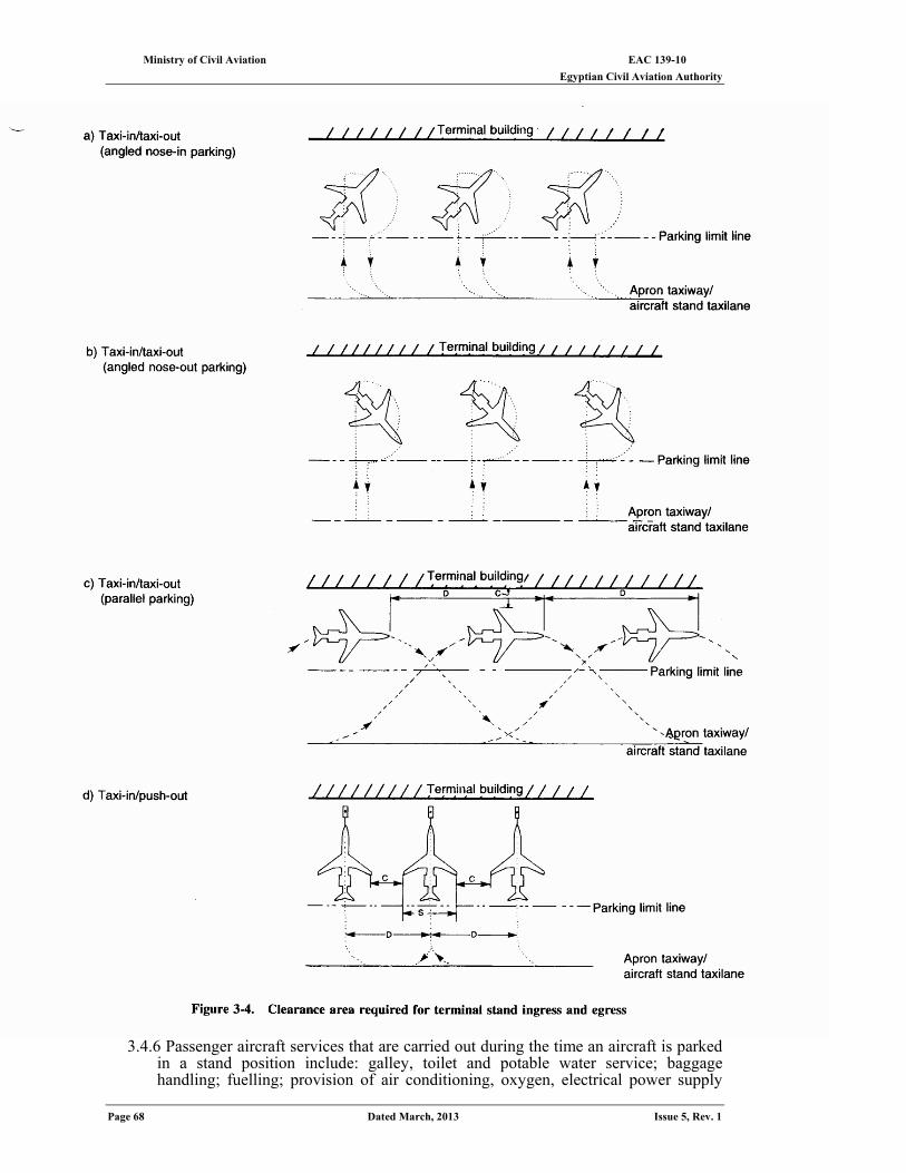
EAC 139-10 Ministry of Civil Aviation Egyptian Civil Aviation Authority
Page 68 Dated March, 2013 Issue 5, Rev. 1
3.4.6 Passenger aircraft services that are carried out during the time an aircraft is parked in a stand position include: galley, toilet and potable water service; baggage handling; fuelling; provision of air conditioning, oxygen, electrical power supply
Ministry of Civil Aviation EAC 139-10 Egyptian Civil Aviation Authority
Issue 5, Rev. 1 Dated March, 2013 Page 69
and starting air; and aircraft towing. Most of these functions have a vehicle and/or equipment associated with them or have some type of fixed installation established to conduct these services. Figure 3-5 shows a typical ground equipment service layout for a medium-sized aircraft. The area to the right of the aircraft nose forward. of the wing is often used as a propositioned service area to store vehicles and equipment when the nose-in/push-out parking configuration is adopted.
Taxiways and service roads
3.4.7 The total area needed for an apron includes not only the individual aircraft stands, but also the area required for apron taxiways, aircraft stand taxi lanes and service roads needed to access the aircraft stands and provide necessary support services. Locations for these facilities will depend upon the terminal arrangement, runway locations and locations of apron services such as flight kitchens, fuel farms, etc.
Apron taxiways
3.4.8 Chapter 1 of this EAC defines apron taxiways and aircraft stand taxi lanes and their interaction with the aircraft stands. Aircraft stand taxi lanes branch of off apron taxiways, which in turn are generally located on the edge of the apron pavement.
Service roads
3.4.9 Chapter 4 of this EAC discusses the need for and location of service roads. The space needed for service roads must be considered during the over-all apron planning. They are usually located either adjacent and parallel to the terminal building or on the air side of the aircraft stand parallel to the aircraft stand taxi lane. The width required will depend upon the anticipated level of traffic and whether a one-way road system can be developed. If the service road is located adjacent to the terminal building, adequate clearance must be available under the loading bridges for the largest vehicles expected to use the road. If the service road is not adjacent to the terminal building, the difficulty of providing the necessary headroom under bridges is eliminated, but it introduces the problem of vehicle/aircraft conflict. Over-all apron planning should also take into account manoeuvring and storage areas for ground equipment.
3.5 apron guidance
In the EAC 139-12Visual Aids, the benefits of apron marking and lighting, as well as guidance on aircraft stands, are discussed. The objective of guidance on aircraft stands is to provide safe manoeuvring of aircraft on the aircraft stand and precise positioning of aircraft. Generally, during good visibility periods, the use of painted lines and, if necessary, Marshallese will ensure safe, accurate movements. Floodlighting on the apron area should be added for night operations and when visibility is poor, pavement centre line lighting should be provided. Visual docking guidance systems have also proven to be beneficial
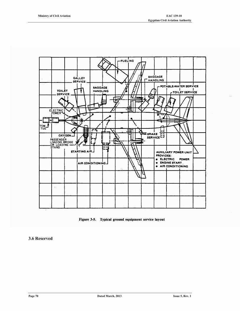
EAC 139-10 Ministry of Civil Aviation Egyptian Civil Aviation Authority
Page 70 Dated March, 2013 Issue 5, Rev. 1
3.6 Reserved
Ministry of Civil Aviation EAC 139-10 Egyptian Civil Aviation Authority
Issue 5, Rev. 1 Dated March, 2013 Page 71
CHAPTER 4
Segregation of traffic on the movement area
4.1 need for traffic segregation 4.1.1 The potential for aircraft and ground vehicle interactions exists on the runways,
taxiways and aprons that make up the aircraft movement area. The number of interactions can be minimized, however, in the planning phase of the aerodrome facility by segregating the air and ground traffic. Properly segregated traffic will minimize the possibility of aircraft and ground vehicle collisions and maximize the efficiency of aircraft movements. Those interactions that are necessary should be planned for predominated areas using established procedures.
4.1.2 There is a need for some ground vehicles to operate on the movement area for the purposes of aircraft servicing, aerodrome maintenance and construction work, and emergency operations. However, because of the different physical characteristics of aerodromes, no specific design criteria can be established to promote segregation of traffic. There are, however, a number of measures that may be taken to lessen the amount of mixing of aircraft and ground vehicles.
4.2 Activities Causing A Mix Of Aircraft And Ground Vehicles
4.2.1 The majority of interactions that can occur between aircraft and ground vehicles take place on apron areas. The following are some aircraft servicing operations performed on aprons that may involve attendance of ground vehicles and that should be taken into account when planning segregation of traffic on aprons:
(a) passenger unloading/loading; (b) baggage unloading/loading; (c) cargo and/or mail unloading/loading; (d) galley service; (e) sanitation service; (f) fuelling service; (g) provision of compressed air for engine starting; (h) aircraft maintenance; and (i)electric power and air conditioning (if not provided by aircraft auxiliary power units).
In addition, provision should be made for emergency and security vehicles on the apron areas. 4.2.2 Ground vehicle activities that occur on movement areas outside of the aprons include
the following: (a) Emergency operations. Rescue and fire fighting equipment, which may be required
at any point on the aerodrome or runway approach areas. (b) Security operations. Small vehicles used for the patrol of fence lines and restricted
areas. (c) Aerodrome maintenance and construction. Repair of pavements, navigation aids and lighting, grass mowing, snow/ice removal operations, etc.
4.3 Methods to Achieve Segregation
4.3.1 Several general concepts for achieving segregation of traffic are presented in the following paragraphs. For apron areas in particular, the degree of segregation which can be achieved depends largely on the available space. The greater the amount of space available for a given number of aircraft stands, the easier it is to segregate types of traffic. Normally, the need for economy is such that aprons are rarely designed with excess area and, in any case, air traffic growth generally absorbs any designed spare apron area. The degree of segregation necessary is dependent on the dimensions and other characteristics of aircraft (e.g. wing span, manoeuvrability and jet blast) and the nature of the ground vehicles. In addition, when planning an aerodrome, aircraft operators should be consulted to determine their anticipated ground vehicle movement requirements.
Exclusion 4.3.2 Although the design of aerodrome facilities can ease considerably the problem of
mixing of aircraft with ground vehicles, it is nevertheless most important that aircraft
EAC 139-10 Ministry of Civil Aviation Egyptian Civil Aviation Authority
Page 72 Dated March, 2013 Issue 5, Rev. 1
operators be conscious of the need to keep the volume of their ground traffic to a minimum. All ground vehicles whose function does not require them to be on the movement area should be excluded. This practice is also in accord with basic aerodrome security measures. Land side road systems should be designed so that public vehicles have access to all public areas of an aerodrome without travelling on the movement area. Measures should also be taken to prevent unauthorized access of public vehicles to the movement area. This requires the provision of fences, gates and other security systems needed to strictly control access.
Service roads for ground vehicles 4.3.3 Air side service roads for ground vehicles can eliminate or lessen to a great extent the
necessity for the use of runways and taxiways by ground vehicles. Such roads should be planned so that at least the critical sections of the movement area for traffic congestion can be bypassed by ground vehicular traffic. For example, these roads may be used as aerodrome perimeter service roads providing access to navigation aids, as temporary roads for construction vehicles or as air side roads between terminal buildings and aprons for the passage of airline vehicles, baggage trains, etc. For terminals with passenger loading bridges, air side roads may (for some designs) pass beneath the immovable part of the loading bridge. Figure 4-1 shows examples of air side service roads used on aprons.
4.3.4 Some general considerations in the planning of roads are described as follows: (a) every effort should be made to plan air side service roads so that they do not cross
runways and taxiways. At high traffic aerodromes, road tunnels beneath runways and taxiways should be considered at major intersections in order to avoid such crossings;
(b) when planning the aerodrome road layout, account should be taken of the need to provide emergency access roads for use by rescue and fire fighting vehicles to various areas on the aerodrome and in particular to the approach areas up to 1 000 m from the threshold, or at least within the aerodrome boundary;
(c) service roads to navigation aids should be planned in such a manner as to present minimal interference to the function of the aids. If it is necessary for an access road to cross an approach area, the road should be located so that vehicles travelling on them are not obstacles to aircraft operations; and
(d) the air side service road system must be designed to account for local security measures. Access points to the system will thus need to be restricted. Should ground vehicle movements affect surface movement of aircraft on runways and taxiways, it will be required that the ground vehicle movements be co-ordinated by the appropriate aerodrome control. Control is normally exercised by means of two-way radio communication, although visual signals, such as signal lamps, are adequate when the traffic at the aerodrome is light. Signs or signals may also be employed to aid control at intersections.
Fixed servicing installations 4.3.5 Many apron service vehicles can be eliminated with the provision of fixed servicing
installations set either within the apron or within the terminal buildings adjacent to the aircraft stands. For example, the provision of hydrant fuelling systems, compressed air outlets, static power supplies, drainage outlets, drinking water hydrants, air conditioning outlets and telephone outlets close to aircraft stands would considerably reduce the equipment and vehicles required for aircraft servicing. Loading bridges for passenger loading and unloading can also be thought of as a form of fixed servicing installation as they eliminate the need for passenger loading equipment and the need for passengers to travel over the apron (either by walking or in a passenger transport vehicle). Furthermore, loading bridges generally lend themselves to the provision of fixtures for aircraft servicing operations. Some of the disadvantages of fixed servicing installations are high initial costs and limited flexibility for different aircraft types. However, if in the planning stage careful consideration is given to the location and number of these facilities, the required flexibility can be achieved. In addition, the different power supply requirements of present-day aircraft complicate the provision of static power supplies; however, the trend in aircraft design is towards greater standardization of electrical requirements.
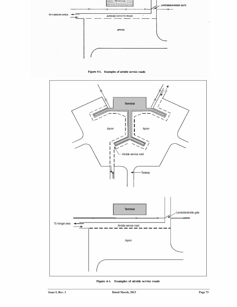
Ministry of Civil Aviation EAC 139-10 Egyptian Civil Aviation Authority
Issue 5, Rev. 1 Dated March, 2013 Page 73
See the EAC 139-15— Master Planning, for planning considerations regarding fixed servicing installations.
Markings 4.3.6 Paint markings should be used to facilitate the segregation of traffic on aprons.
Markings can be used to provide guidance to pilots in maneuvering their aircraft safely and expeditiously on aprons. Other markings are used to designate safety limits for placement of equipment on aprons, e.g. wing tip clearance lines and other markings used to delineate access routes for ground vehicles, passengers or personnel across the apron. There should be a color change between lines to distinguish one from another.
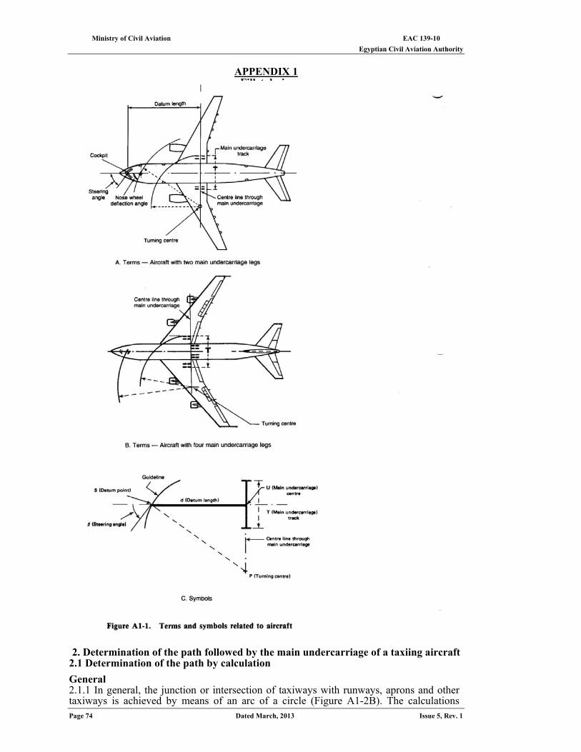
EAC 139-10 Ministry of Civil Aviation Egyptian Civil Aviation Authority
Page 74 Dated March, 2013 Issue 5, Rev. 1
APPENDIX 1
Fillet design
1. Terminology and Symbols 1.1 General
A description of the terms and symbols used in this appendix is given below. Throughout this appendix it is assumed that the aircraft is taxiing on a horizontal pavement.
1.2 Terms related to the aircraft (see Figure A1-1) Datum point of aircraft (S). Point on longitudinal axis of aircraft which follows the guideline on the ground. The datum point is located vertically beneath the cockpit of the aircraft. Turning centre (P). Centre of turn of aircraft at any time. Centre line through main undercarriage. Line from the turning centre perpendicular to the aircraft longitudinal axis. Datum length (d). Distance between aircraft datum point and centre line through undercarriage. Main undercarriage centre (U). Point of intersection of longitudinal aircraft axis and centre line through main undercarriage. Track of the main undercarriage (T). Distance between the outer main wheels of aircraft including the width of the wheels. Steering angle (β). Angle formed by the tangent to the guideline and the longitudinal axis of aircraft. Nose wheel steering angle. Angle formed by the longitudinal axis of aircraft and the direction of the nose wheel. 1.3 Terms related to taxiway and fillet design (see Figure A1-2) Guideline. Line applied to the pavement by means of markings and/or lights which the aircraft datum point must follow while taxiing. Guideline centre (O). Centre of curvature of guideline at point S. Deviation of main undercarriage (λ). Distance between main undercarriage centre (U) and the guideline measured at right angles to the latter. 1.4 Glossary of symbols The following symbols are used when describing the path of the main undercarriage centre and the design of the fillets (see Figures Al-1 and A1-2). d = aircraft datum length M = minimum clearance distance between outer wheels of main undercarriage leg and edge of pavement 0 = centre of curvature of guideline at point S P = turning centre r = radius of fillet arc R = radius of curvature of guideline at point S S = datum point of aircraft T = track of the main undercarriage U = main undercarriage centre α=angle between the radial line OU and the tangent to the path of the main undercarriage centre at U β= steering angle λ= main undercarriage deviation Q and θ =polar coordinates of a point [(S) or (U ), as applicable]
2. Determination of the path followed by the main undercarriage of a taxiing aircraft 2.1 Determination of the path by calculation
General 2.1.1 In general, the junction or intersection of taxiways with runways, aprons and other taxiways is achieved by means of an arc of a circle (Figure A1-2B). The calculations
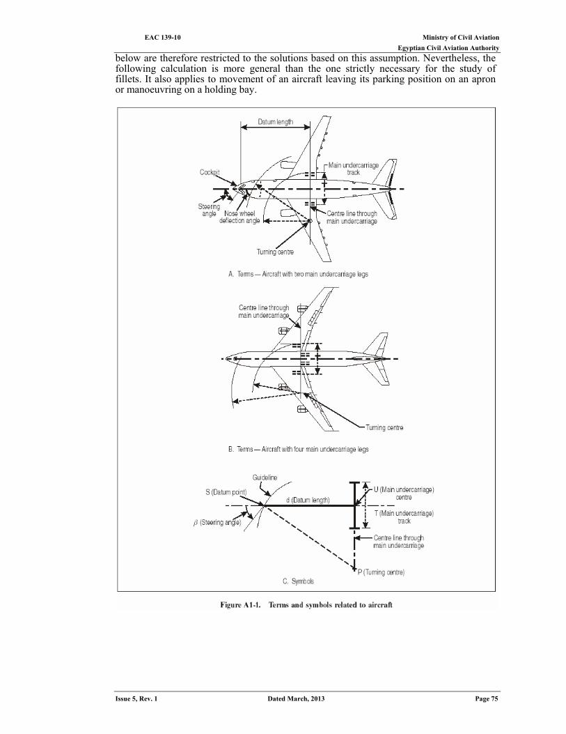
Ministry of Civil Aviation EAC 139-10 Egyptian Civil Aviation Authority
Issue 5, Rev. 1 Dated March, 2013 Page 75
below are therefore restricted to the solutions based on this assumption. Nevertheless, the following calculation is more general than the one strictly necessary for the study of fillets. It also applies to movement of an aircraft leaving its parking position on an apron or manoeuvring on a holding bay.
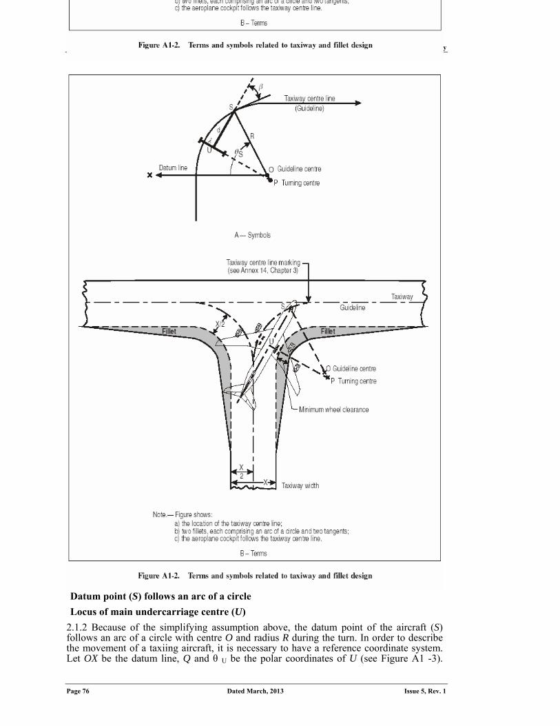
EAC 139-10 Ministry of Civil Aviation Egyptian Civil Aviation Authority
Page 76 Dated March, 2013 Issue 5, Rev. 1
Datum point (S) follows an arc of a circle
Locus of main undercarriage centre (U)
2.1.2 Because of the simplifying assumption above, the datum point of the aircraft (S) follows an arc of a circle with centre O and radius R during the turn. In order to describe the movement of a taxiing aircraft, it is necessary to have a reference coordinate system. Let OX be the datum line, Q and θ U be the polar coordinates of U (see Figure A1 -3).
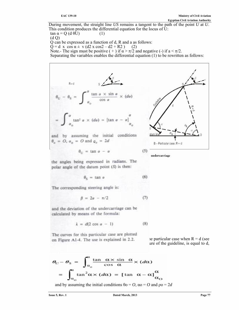
Ministry of Civil Aviation EAC 139-10 Egyptian Civil Aviation Authority
Issue 5, Rev. 1 Dated March, 2013 Page 77
During movement, the straight line US remains a tangent to the path of the point U at U. This condition produces the differential equation for the locus of U: tan α = Q (d θU) (1) (d Q) Q can be expressed as a function of d, R and a as follows: Q = d x cos α ± v (d2 x cos2 – d2 + R2 ) (2) Note.- The sign must be positive ( + ) if α > /2 and negative (-) if a < /2. Separating the variables enables the differential equation (1) to be rewritten as follows:
2.1.3 Special case: R = d. Integration is only easy in the particular case when R = d (see Figure AI-313). Indeed, if R, the radius of curvature of the guideline, is equal to d, then the datum length of the aircraft would be:
and by assuming the initial conditions θo = O, αo = O and ρo = 2d
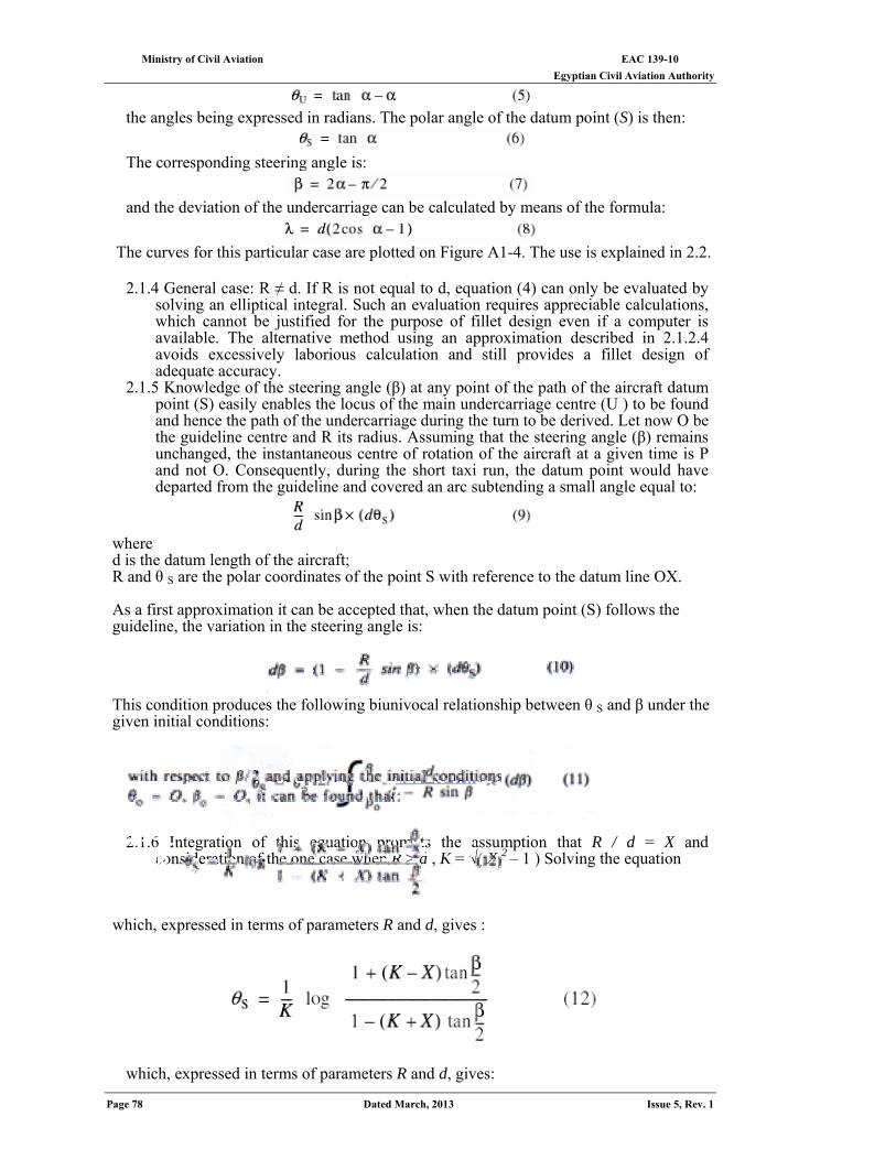
EAC 139-10 Ministry of Civil Aviation Egyptian Civil Aviation Authority
Page 78 Dated March, 2013 Issue 5, Rev. 1
the angles being expressed in radians. The polar angle of the datum point (S) is then:
The corresponding steering angle is:
and the deviation of the undercarriage can be calculated by means of the formula:
The curves for this particular case are plotted on Figure A1-4. The use is explained in 2.2.
2.1.4 General case: R ≠ d. If R is not equal to d, equation (4) can only be evaluated by
solving an elliptical integral. Such an evaluation requires appreciable calculations, which cannot be justified for the purpose of fillet design even if a computer is available. The alternative method using an approximation described in 2.1.2.4 avoids excessively laborious calculation and still provides a fillet design of adequate accuracy.
2.1.5 Knowledge of the steering angle (β) at any point of the path of the aircraft datum point (S) easily enables the locus of the main undercarriage centre (U ) to be found and hence the path of the undercarriage during the turn to be derived. Let now O be the guideline centre and R its radius. Assuming that the steering angle (β) remains unchanged, the instantaneous centre of rotation of the aircraft at a given time is P and not O. Consequently, during the short taxi run, the datum point would have departed from the guideline and covered an arc subtending a small angle equal to:
where d is the datum length of the aircraft; R and θ S are the polar coordinates of the point S with reference to the datum line OX.
As a first approximation it can be accepted that, when the datum point (S) follows the guideline, the variation in the steering angle is:
This condition produces the following biunivocal relationship between θ S and β under the given initial conditions:
2.1.6 Integration of this equation prompts the assumption that R / d = X and
consideration of the one case when R > d , K = √( X 2 – 1 ) Solving the equation which, expressed in terms of parameters R and d, gives :
which, expressed in terms of parameters R and d, gives:
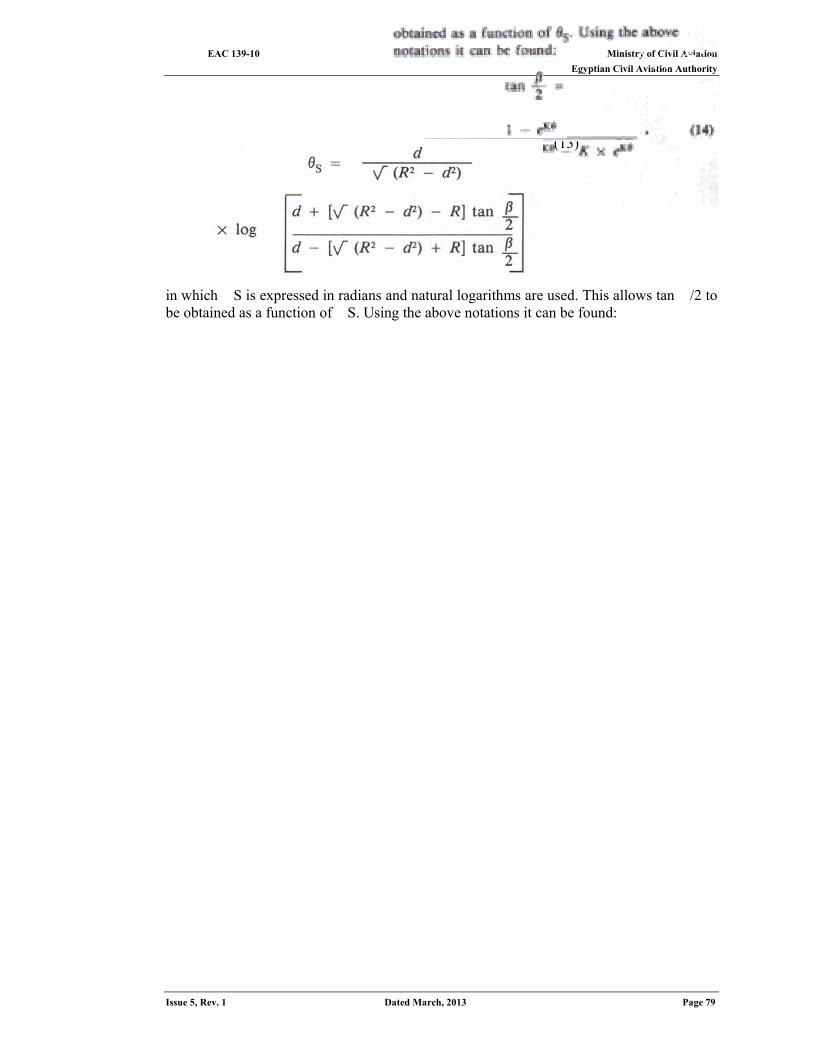
Ministry of Civil Aviation EAC 139-10 Egyptian Civil Aviation Authority
Issue 5, Rev. 1 Dated March, 2013 Page 79
(13)
in which �S is expressed in radians and natural logarithms are used. This allows tan �/2 to be obtained as a function of �S. Using the above notations it can be found:
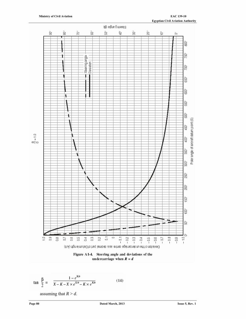
EAC 139-10 Ministry of Civil Aviation Egyptian Civil Aviation Authority
Page 80 Dated March, 2013 Issue 5, Rev. 1
assuming that R > d.
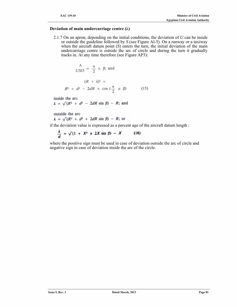
Ministry of Civil Aviation EAC 139-10 Egyptian Civil Aviation Authority
Issue 5, Rev. 1 Dated March, 2013 Page 81
Deviation of main undercarriage centre (λ)
2.1.7 On an apron, depending on the initial conditions, the deviation of U can be inside
or outside the guideline followed by S (see Figure Al-5). On a runway or a taxiway when the aircraft datum point (S) enters the turn, the initial deviation of the main undercarriage centre is outside the arc of circle and during the turn it gradually tracks in. At any time therefore (see Figure AP3):
if the deviation value is expressed as a percent age of the aircraft datum length :
where the positive sign must be used in case of deviation outside the arc of circle and negative sign in case of deviation inside the arc of the circle.
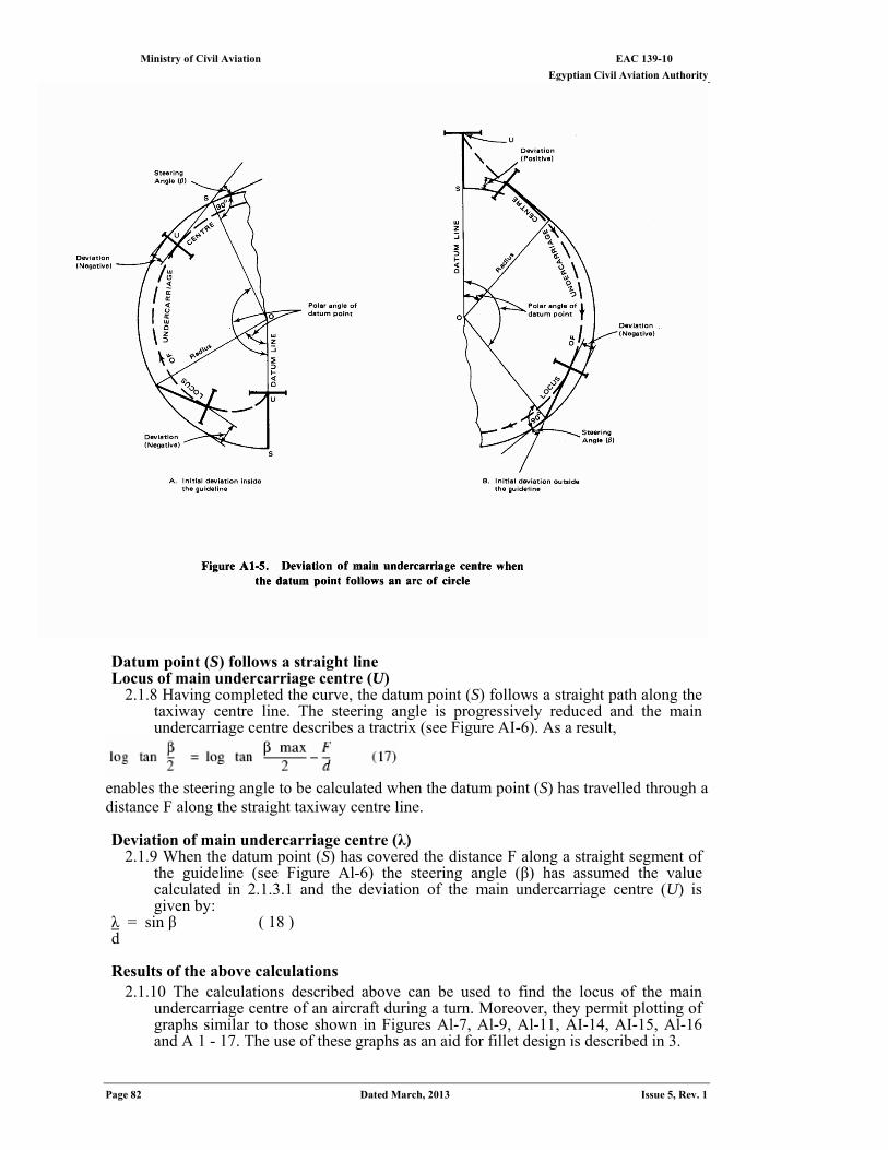
EAC 139-10 Ministry of Civil Aviation Egyptian Civil Aviation Authority
Page 82 Dated March, 2013 Issue 5, Rev. 1
Datum point (S) follows a straight line Locus of main undercarriage centre (U)
2.1.8 Having completed the curve, the datum point (S) follows a straight path along the taxiway centre line. The steering angle is progressively reduced and the main undercarriage centre describes a tractrix (see Figure AI-6). As a result,
enables the steering angle to be calculated when the datum point (S) has travelled through a distance F along the straight taxiway centre line. Deviation of main undercarriage centre (λ)
2.1.9 When the datum point (S) has covered the distance F along a straight segment of the guideline (see Figure Al-6) the steering angle (β) has assumed the value calculated in 2.1.3.1 and the deviation of the main undercarriage centre (U) is given by:
)18 ( βsin = λ d
Results of the above calculations 2.1.10 The calculations described above can be used to find the locus of the main
undercarriage centre of an aircraft during a turn. Moreover, they permit plotting of graphs similar to those shown in Figures Al-7, Al-9, Al-11, AI-14, AI-15, Al-16 and A 1 - 17. The use of these graphs as an aid for fillet design is described in 3.
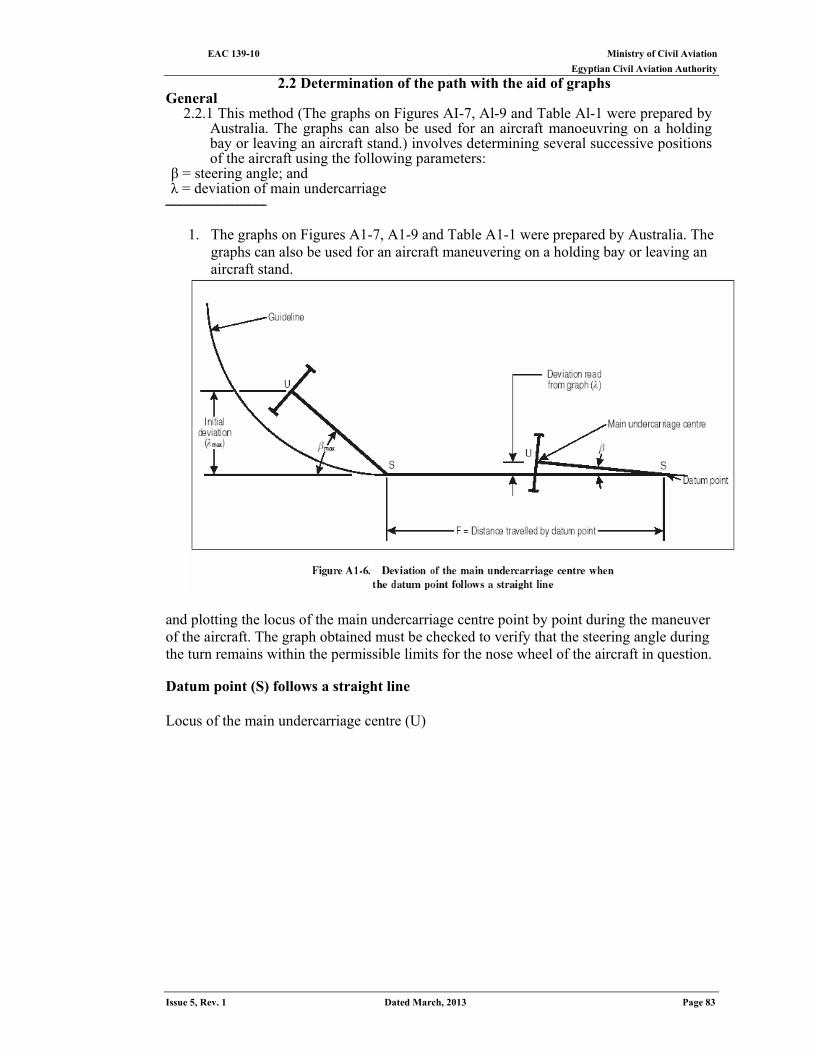
Ministry of Civil Aviation EAC 139-10 Egyptian Civil Aviation Authority
Issue 5, Rev. 1 Dated March, 2013 Page 83
2.2 Determination of the path with the aid of graphs General
2.2.1 This method (The graphs on Figures AI-7, Al-9 and Table Al-1 were prepared by Australia. The graphs can also be used for an aircraft manoeuvring on a holding bay or leaving an aircraft stand.) involves determining several successive positions of the aircraft using the following parameters:
β = steering angle; and λ = deviation of main undercarriage
ـــــــــــــــــــــــــــــــــــــــ
1. The graphs on Figures A1-7, A1-9 and Table A1-1 were prepared by Australia. The graphs can also be used for an aircraft maneuvering on a holding bay or leaving an aircraft stand.
and plotting the locus of the main undercarriage centre point by point during the maneuver of the aircraft. The graph obtained must be checked to verify that the steering angle during the turn remains within the permissible limits for the nose wheel of the aircraft in question. Datum point (S) follows a straight line Locus of the main undercarriage centre (U)

Ministry of Civil Aviation EAC 139-10 Egyptian Civil Aviation Authority
Page 84 Dated March, 2013 Issue 5, Rev. 1
2.2.2 Figure Al-7 gives the deviation of the main undercarriage centre from a straight
line knowing the initial deviation from that line and the distance travelled along it by the datum point.
Example An aircraft of datum length 18m follows a straight line for a distance of 40 m, as shown in Figure Al-8. Step 1. Scale the deviation of the main undercarriage centre at the point where the datum
point commenced to travel around the curve.
Step 2. The distance of 40 m traveled by the datum point is 216.7% of the datum length.
Step 3. The deviation of the undercarriage centre after the datum point has travelled
along the straight line is 8.75% of the datum length as shown on Figure A1-7. The deviation in this position is 1.60 m.
Datum point (S) follows an arc of a circle Locus of the main undercarriage centre (U)
2.2.3 The graphs on Figure A1-9 have been drawn for selected values of the ratio:
The graphs have been prepared for R/d values ranging between 0.5 and 10.0. These values are marked above every graph which shows:
a) the deviation of the main undercarriage centre; b) the steering angle (dashed curve)
as a function of the values assumed by the polar angle of the aircraft datum point.
Example
An aircraft of datum length 18 m follows an arc of circle of radius 27 m, as shown in Figure A1-10. Step 1. Scale the deviation of the main undercarriage centre at the point where the datum
point commenced to travel around the curve.
Deviation = 12.15 m = +0.675 of the datum length
Step 3. From Figure A1-11 for R/d = 1.5, read the polar angle of the datum point
corresponding to the deviation obtained in step 1.
Deviation = +0.675 Polar angle of datum point = 27.5°.
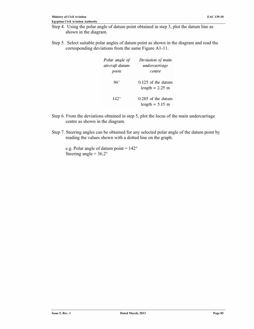
Ministry of Civil Aviation EAC 139-10
Egyptian Civil Aviation Authority
Issue 5, Rev. 1 Dated March, 2013 Page 85
Step 4. Using the polar angle of datum point obtained in step 3, plot the datum line as shown in the diagram.
Step 5. Select suitable polar angles of datum point as shown in the diagram and read the
corresponding deviations from the same Figure A1-11.
Step 6. From the deviations obtained in step 5, plot the locus of the main undercarriage
centre as shown in the diagram. Step 7. Steering angles can be obtained for any selected polar angle of the datum point by
reading the values shown with a dotted line on the graph.
e.g. Polar angle of datum point = 142° Steering angle = 36.2°
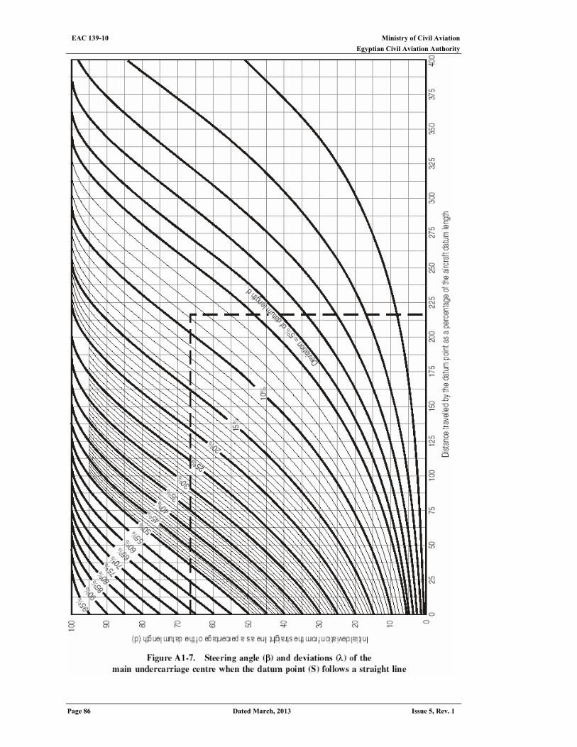
Ministry of Civil Aviation EAC 139-10 Egyptian Civil Aviation Authority
Page 86 Dated March, 2013 Issue 5, Rev. 1
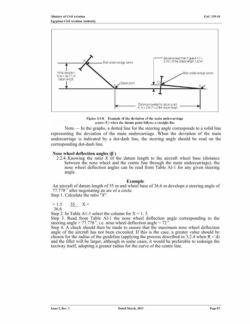
Ministry of Civil Aviation EAC 139-10
Egyptian Civil Aviation Authority
Issue 5, Rev. 1 Dated March, 2013 Page 87
Note.— In the graphs, a dotted line for the steering angle corresponds to a solid line
representing the deviation of the main undercarriage. When the deviation of the main undercarriage is indicated by a dot-dash line, the steering angle should be read on the corresponding dot-dash line. Nose wheel deflection angles (β )
2.2.4 Knowing the ratio X of the datum length to the aircraft wheel base (distance between the nose wheel and the centre line through the main undercarriage), the nose wheel deflection angles can be read from Table Al-1 for any given steering angle.
Example
An aircraft of datum length of 55 m and wheel base of 36.6 m develops a steering angle of 77.778 ο after negotiating an arc of a circle.
Step 1. Calculate the ratio "X".
= X 55 1.5= 36.6
Step 2. In Table A1-1 select the column for X = 1. 5. Step 3. Read from Table Al-1 the nose wheel deflection angle corresponding to the steering angle = 77.778 ο, i.e. nose wheel deflection angle = 72 ο. Step 4. A check should then be made to ensure that the maximum nose wheel deflection angle of the aircraft has not been exceeded. If this is the case, a greater value should be chosen for the radius of the guideline (applying the process described in 3.2.4 when R < d) and the fillet will be larger, although in some cases, it would be preferable to redesign the taxiway itself, adopting a greater radius for the curve of the centre line.
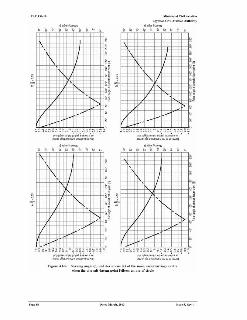
Ministry of Civil Aviation EAC 139-10 Egyptian Civil Aviation Authority
Page 88 Dated March, 2013 Issue 5, Rev. 1
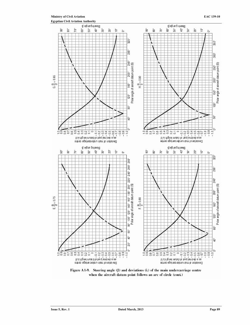
Ministry of Civil Aviation EAC 139-10
Egyptian Civil Aviation Authority
Issue 5, Rev. 1 Dated March, 2013 Page 89
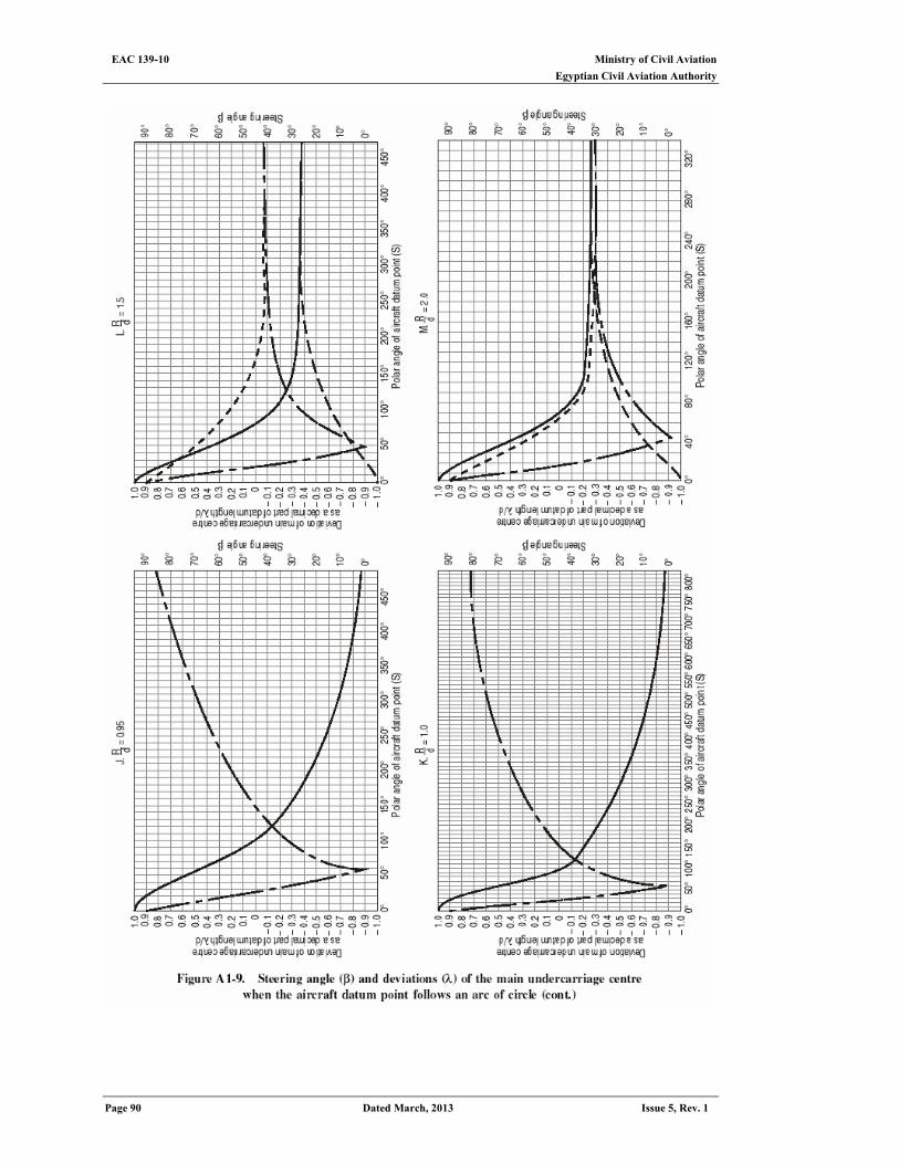
Ministry of Civil Aviation EAC 139-10 Egyptian Civil Aviation Authority
Page 90 Dated March, 2013 Issue 5, Rev. 1
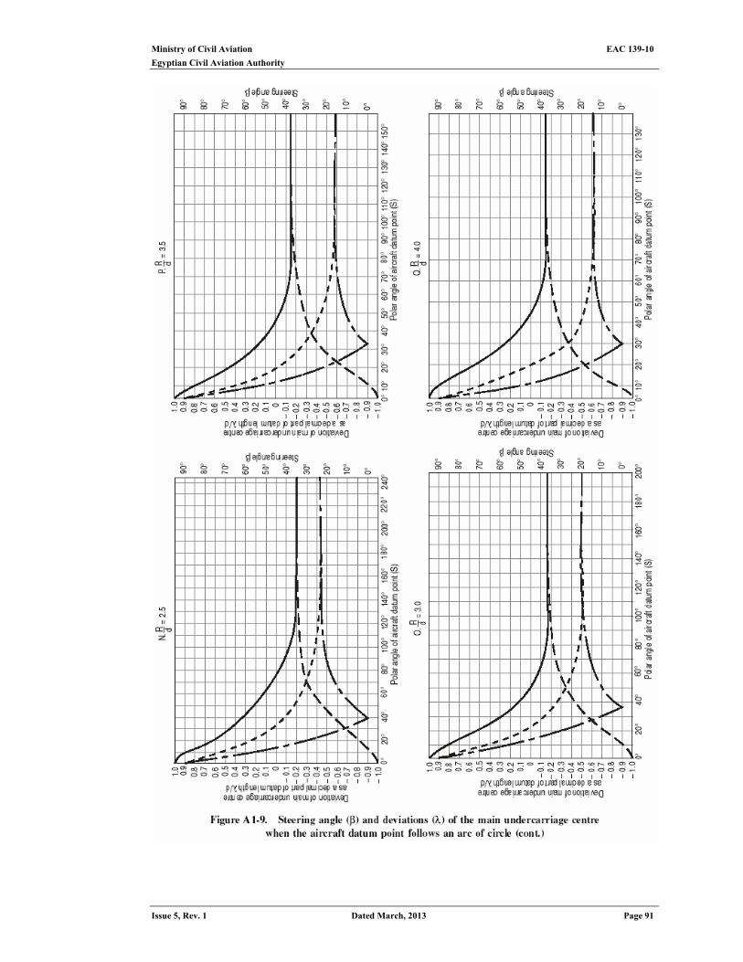
Ministry of Civil Aviation EAC 139-10
Egyptian Civil Aviation Authority
Issue 5, Rev. 1 Dated March, 2013 Page 91
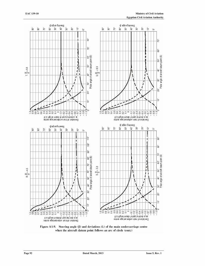
Ministry of Civil Aviation EAC 139-10 Egyptian Civil Aviation Authority
Page 92 Dated March, 2013 Issue 5, Rev. 1
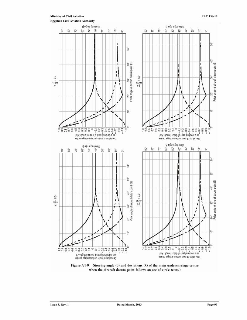
Ministry of Civil Aviation EAC 139-10
Egyptian Civil Aviation Authority
Issue 5, Rev. 1 Dated March, 2013 Page 93
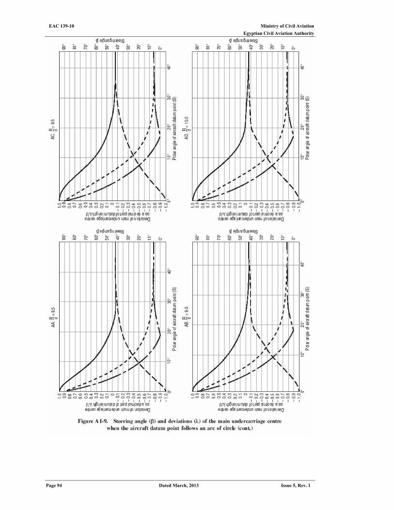
Ministry of Civil Aviation EAC 139-10 Egyptian Civil Aviation Authority
Page 94 Dated March, 2013 Issue 5, Rev. 1
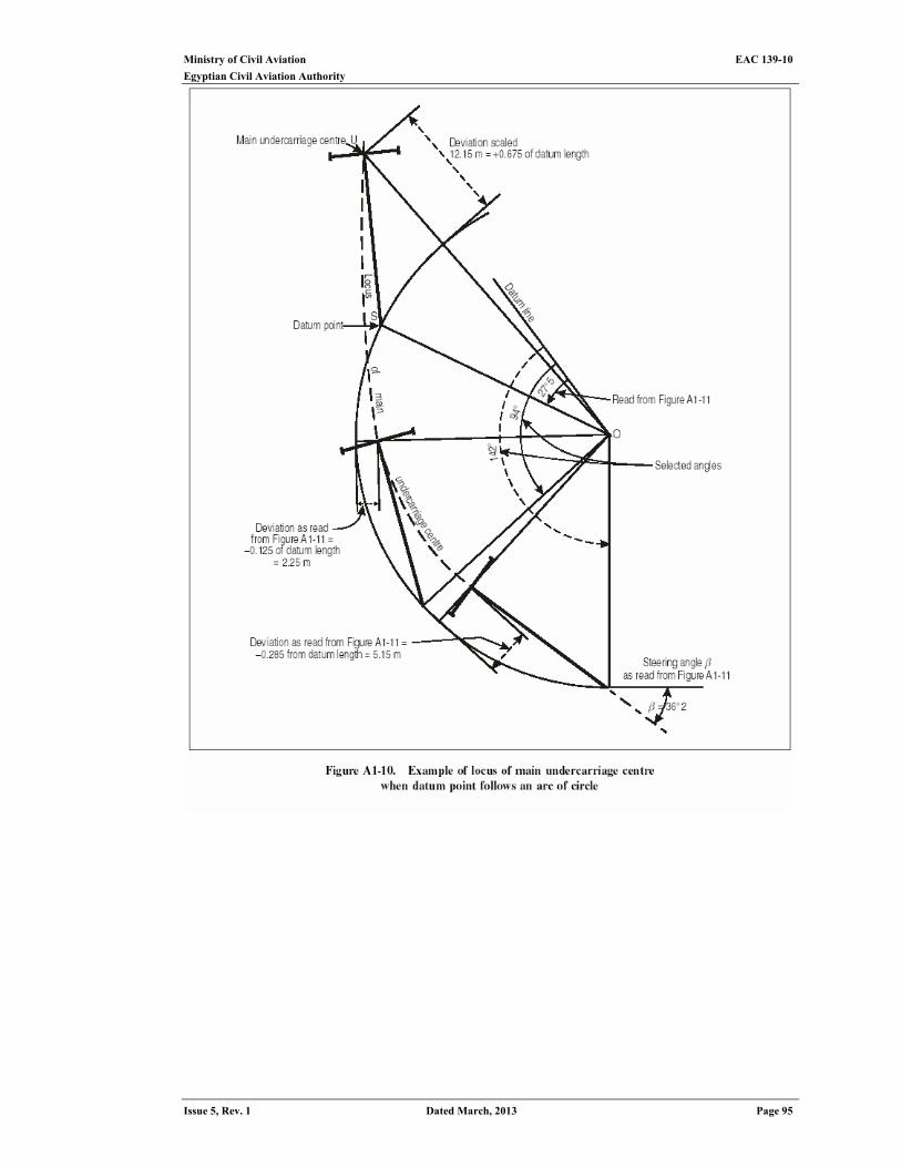
Ministry of Civil Aviation EAC 139-10
Egyptian Civil Aviation Authority
Issue 5, Rev. 1 Dated March, 2013 Page 95
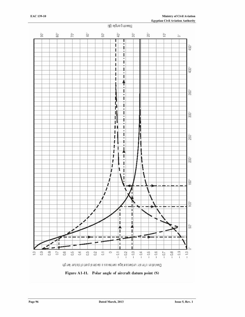
Ministry of Civil Aviation EAC 139-10 Egyptian Civil Aviation Authority
Page 96 Dated March, 2013 Issue 5, Rev. 1
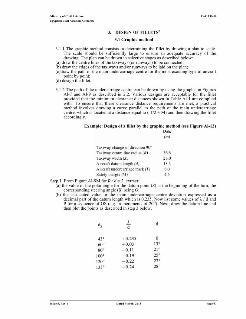
Ministry of Civil Aviation EAC 139-10
Egyptian Civil Aviation Authority
Issue 5, Rev. 1 Dated March, 2013 Page 97
3.1 Graphic method
3.1.1 The graphic method consists in determining the fillet by drawing a plan to scale.
The scale should be sufficiently large to ensure an adequate accuracy of the drawing. The plan can be drawn in selective stages as described below:
(a) draw the centre lines of the taxiways (or runways) to be connected; (b) draw the edges of the taxiways and/or runways to be laid on the plan; (c)draw the path of the main undercarriage centre for the most exacting type of aircraft
point by point; (d) design the fillet.
3.1.2 The path of the undercarriage centre can be drawn by using the graphs on Figures
Al-7 and Al-9 as described in 2.2. Various designs are acceptable for the fillet provided that the minimum clearance distances shown in Table Al-1 are complied with. To ensure that these clearance distance requirements are met, a practical method involves drawing a curve parallel to the path of the main undercarriage centre, which is located at a distance equal to ( T/2 + M) and then drawing the fillet accordingly.
Example: Design of a fillet by the graphic method (see Figure Al-12)
Step 1. From Figure Al-9M for R / d = 2, extract:
(a) the value of the polar angle for the datum point (S) at the beginning of the turn, the corresponding steering angle (β) being O;
(b) the associated value or the main undercarriage centre deviation expressed as a decimal part of the datum length which is 0.235. Now list some values of λ / d and P for a sequence of OS (e.g. in increments of 20O). Next, draw the datum line and then plot the points as described in step 3 below.
Ministry of Civil Aviation EAC 139-10 Egyptian Civil Aviation Authority
Page 98 Dated March, 2013 Issue 5, Rev. 1
Step 2.Figure Al-7 enables the following values of λ/d for a sequence of F/d to be found for the initial deviation λ / d = sin 28° = 0.47.
Step 3. The curves can be drawn as follows:
(a) draw the datum line as shown in Figure A1-12; (b) for each value of θS selected in step 1, plot the corresponding point U. For this,
locate point S on the guideline, draw the longitudinal axis of aircraft with corre-sponding steering angle β and mark U at a distance d = 18.3 m from S. Using the values of λ / d in step 1, check the accuracy of the plotting;
c)where the datum point S again follows a straight line after coming out of the turn, using the values of λ / d and F / d from step 2, plot the locus of the undercarriage centre as shown in Figure Al-12;
d) on a perpendicular dropped from U onto the aircraft longitudinal axis, plot a distance inwards equal to ( T / 2 + M ) = 4 + 4.5 = 8.50 m for each selected position of U. The line through these points is the curve parallel to the path of the main undercarriage centre. This is a theoretical minimum limit for the fillet.
Note.- If the taxiway could be used by aircraft in both directions, draw the relevant curve as well.
e)select a design of fillet which can easily be staked out. As a rule it is preferable to choose an outline made up of straight sections and an arc of a circle. In the case in question an arc with a radius of 31.7 m is the easiest outline (Figure A1-12).
Step 4.Cheek the validity of the design, Figure Al-12: (a) the clearance distance is 4.50 m in compliance with the minimum recommended in
ECAR 139 subpart d see table (1-1) (b) the maximum value (28 ο) of the steering angle is compatible with the operational
limits of the nose wheel deflection for all the types of aircraft likely to use the aerodrome.
3.2 Are-and-tangent method
3.2.1 The path of the main undercarriage centre of an aircraft during a turn is a complex curve, but it approximates an arc of a circle and its tangents. A design for a fillet which closely follows the main undercarriage path and allows for the safety margin required can be obtained by using:
(a) an arc concentric with the taxiway centre line in order to provide the necessary additional width of pavement inside the turn; and
(b) a tangent at each end of the arc providing a wedge-shaped end of the fillet to cater for residual deviation of the main undercarriage.
For drawing the fillet, it is sufficient to know the radius (r) of the arc and the length (l) of the wedge-shaped ends of the fillet (see Figure Al-13).
Determination of the radius of the fillet (r)
3.2.2The fillet radius is equal to: r = R – ( λ max + M + T/2 ) in which
R = radius of taxiway centre line taken as guideline λ max = maximum value of the deviation of the main undercarriage
M = minimum safety margin T = track of main undercarriage
3.2.3 The maximum value of the main undercarriage deviation λ max depends on the datum length (d), the radius of curvature of the taxiway centre line (R) and the rate of change in direction. This maximum value is obtained from Figure Al-14 as a
Ministry of Civil Aviation EAC 139-10
Egyptian Civil Aviation Authority
Issue 5, Rev. 1 Dated March, 2013 Page 99
percentage of the aircraft datum length for any value of ratio R/d included between 1 and 5.
3.2.4 When the aircraft datum length (d) is greater than the centre line radius (R), a construction line should be used with a value for the radius equal to the datum length, assuming R / d = 1. The points at which this construction line joins the straight section of the taxiway centre line should be marked for drawing in the wedge-shaped ends (see 3.2.8).
Determination of the length of the wedge-shaped ends
3.2.5 Filleting is no longer required at the point where the main undercarriage deviation becomes less than the maximum deviation permissible without filleting:
λ = X / 2 _ ( M + T/2) where X = taxiway width M = minimum safety margin T = track of main undercarriage The residual deviation is reached at the end of the turn, when the datum point (S) has covered along the straight taxiway centre line a distance F given by the equation (17) in 2.1.3. 1. The length of each wedge-shaped end of the fillet is therefore: l = F – d
3.2.6 Equation (17) enables F to be expressed as function of: (a) β, residual steering angle corresponding to λ, as obtained in 3.2.5 above; and (b) β max, maximum value of the steering angle during a turn. This value is reached
when A is equal to I max, as given by Figure Al-14. Use of prepared graphs avoids all calculation. The residual steering angle reached when the deviation is equal to the maximum permissible deviation without filleting is obtainable from Figure Al-15. (Figures are given to cover a datum length range between 12 and 60 m.) The maximum value of the steering angle during a turn is obtained from Figure Al-16 by reading from the taxiway change of direction to the ratio R / d and across to obtain the steering angle. Finally, Figure A1-17 enables the values of the steering angle to be converted into displacements along the straight guideline.
3.2.7 Care should be taken to ensure that the steering angle does not exceed the maximum nose wheel angle of the aircraft which are expected to use the aerodrome. If that were the case, the radius of curvature of the guideline and the size of fillet will have to be increased.
Note. - Because the datum point does not generally coincide with the nose wheel, this introduces a slight error. This error, however, is on the safe side. Drawing the fillet
3.2.8 The required fillet is obtained as follows: (a) Draw an arc concentric with the taxiway centre line using radius (r) (or, if necessary,
an arc concentric with the construction line mentioned in 3.2.4). (b) Along the inside edge of the taxiway, mark Q 1, and Q 2 at distance l from the
curved section of the guideline, as shown in Figure A1-13. (c) From the points obtained in (b) above, draw tangents to the arc with radius (r). 3.2.9 The arc-and-tangent method is illustrated in Example 1 below.
Variant of arc-and-tangent method
3.2.10 A closer approximation to the required fillet can be obtained by the use of two fairing lines. The second point is obtained by recalculating the maximum permissible deviation without fillet but using a smaller safety margin. The practical method and the result obtained are illustrated in Example 2.
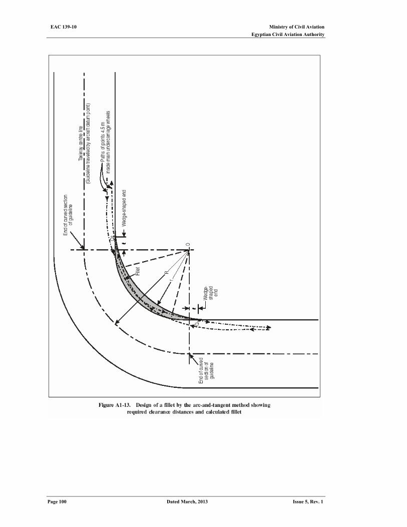
Ministry of Civil Aviation EAC 139-10 Egyptian Civil Aviation Authority
Page 100 Dated March, 2013 Issue 5, Rev. 1
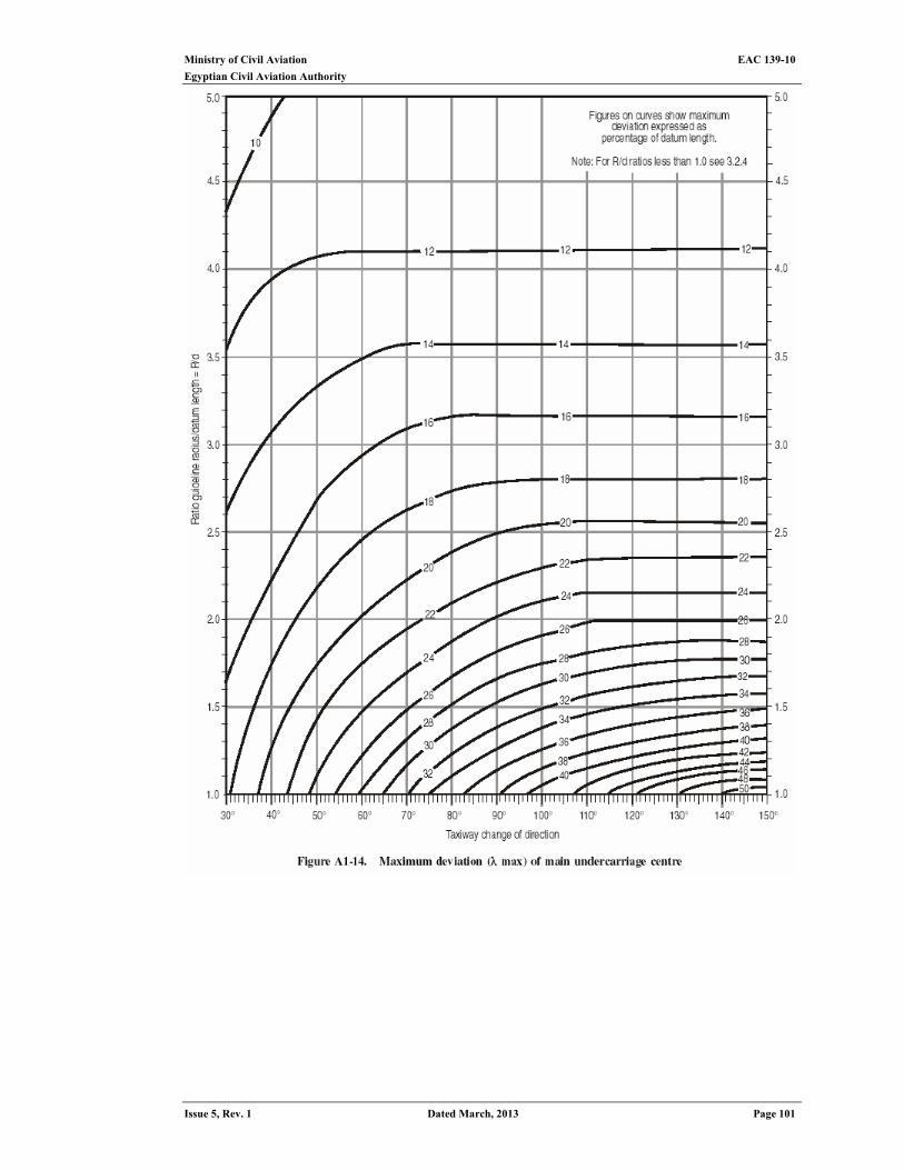
Ministry of Civil Aviation EAC 139-10
Egyptian Civil Aviation Authority
Issue 5, Rev. 1 Dated March, 2013 Page 101

Ministry of Civil Aviation EAC 139-10 Egyptian Civil Aviation Authority
Page 102 Dated March, 2013 Issue 5, Rev. 1
3.3 Quick reference graph method
3.3.1 The quick reference graphs enable the fillets of taxiways to be designed in a relatively simple manner, provided that constant values are given to certain variables: -the width of the taxiways and the minimum clearance distance: corresponding to
the code letter of longest runway served; - datum length and undercarriage track: corresponding to most demanding type of
aircraft involved. 3.3.2 Figures Al-20 and Al-21 have been prepared for two particular types of aircraft,
namely the Boeing 747 and the Concorde, and have been plotted on the basis of the following constant values, as recommended by ECAR 139:
X - width of taxiways = 23 m M - minimum clearance distance = 4.5 m and taking as a guideline the taxiway centre line. In accordance with the provisions of ECAR 139:the datum point selected is located vertically beneath the cockpit. The following constant values relate to each of the types of aircraft:
B747 Concorde
Parameter (M) (M)
Datum length of aircraft (d) 27.7 29.5 Undercarriage track (T) 12.8 8.5
3.3.3 The edge of the fillet (Figure A1-22) is determined as follows:
Step 1.First the radius of the fillet are (r) is determined by plotting the point corresponding to the change in direction of the taxiway and of the centre line curve radius on graph A in Figure Al-20 or Al-21 according to the type of aircraft. The value obtained by interpolation between the curves drawn for round values of r is used to draw an arc concentric to that of the guideline. Step 2.The distance travelled (F) from the point when the fillet becomes unnecessary is obtained in the same manner by means of graph B on Figures Al-20 and Al-21 according to the type of aircraft. This gives the distance from the point where the inside edge of the taxiway becomes straight again. Step 3.The arc tangents are drawn so that they intersect the edge of the taxiway at the end of the distance travelled (F). The line obtained is the required fillet as shown in the diagram (FigureA1-22)
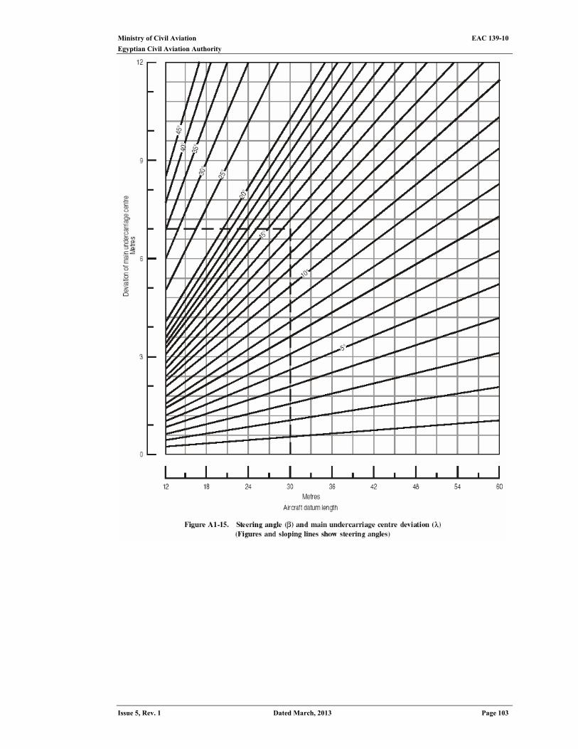
Ministry of Civil Aviation EAC 139-10
Egyptian Civil Aviation Authority
Issue 5, Rev. 1 Dated March, 2013 Page 103

Ministry of Civil Aviation EAC 139-10 Egyptian Civil Aviation Authority
Page 104 Dated March, 2013 Issue 5, Rev. 1
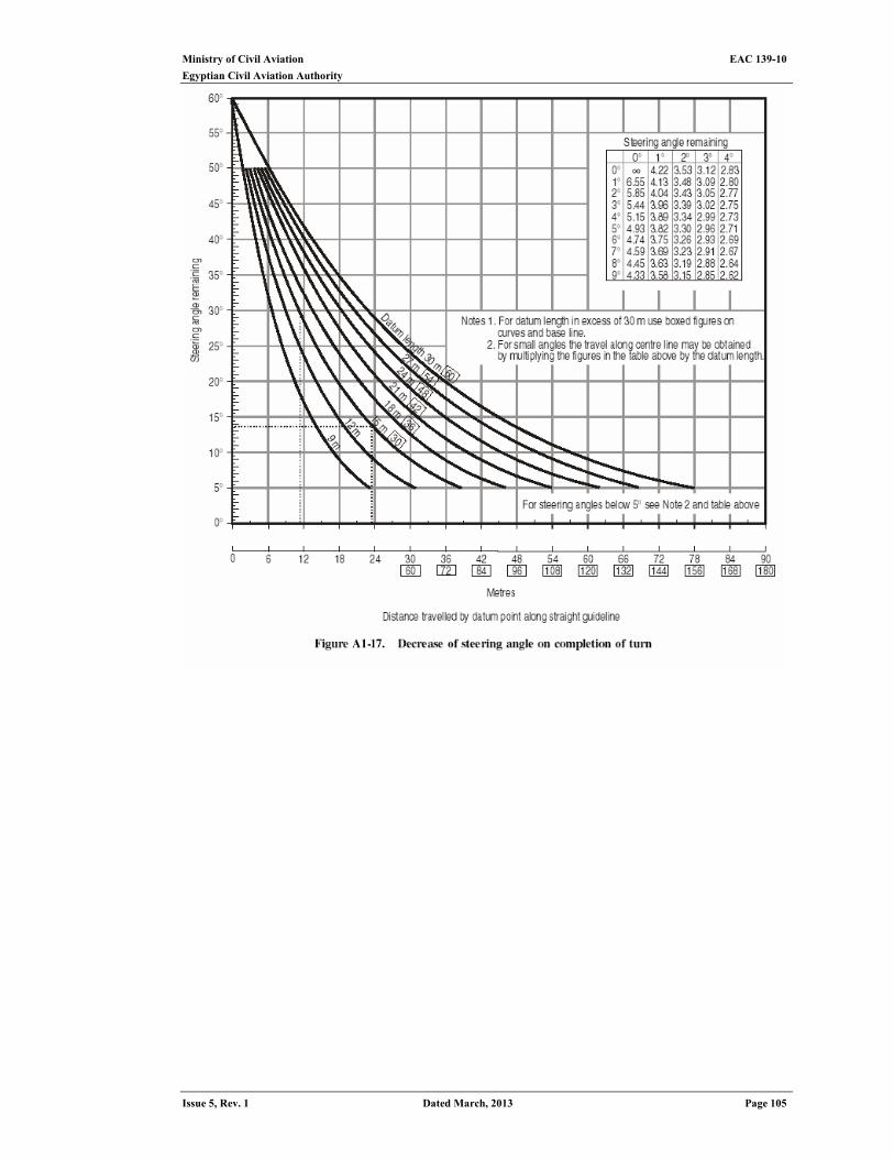
Ministry of Civil Aviation EAC 139-10
Egyptian Civil Aviation Authority
Issue 5, Rev. 1 Dated March, 2013 Page 105
Ministry of Civil Aviation EAC 139-10 Egyptian Civil Aviation Authority
Page 106 Dated March, 2013 Issue 5, Rev. 1
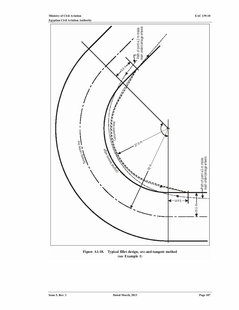
Ministry of Civil Aviation EAC 139-10
Egyptian Civil Aviation Authority
Issue 5, Rev. 1 Dated March, 2013 Page 107
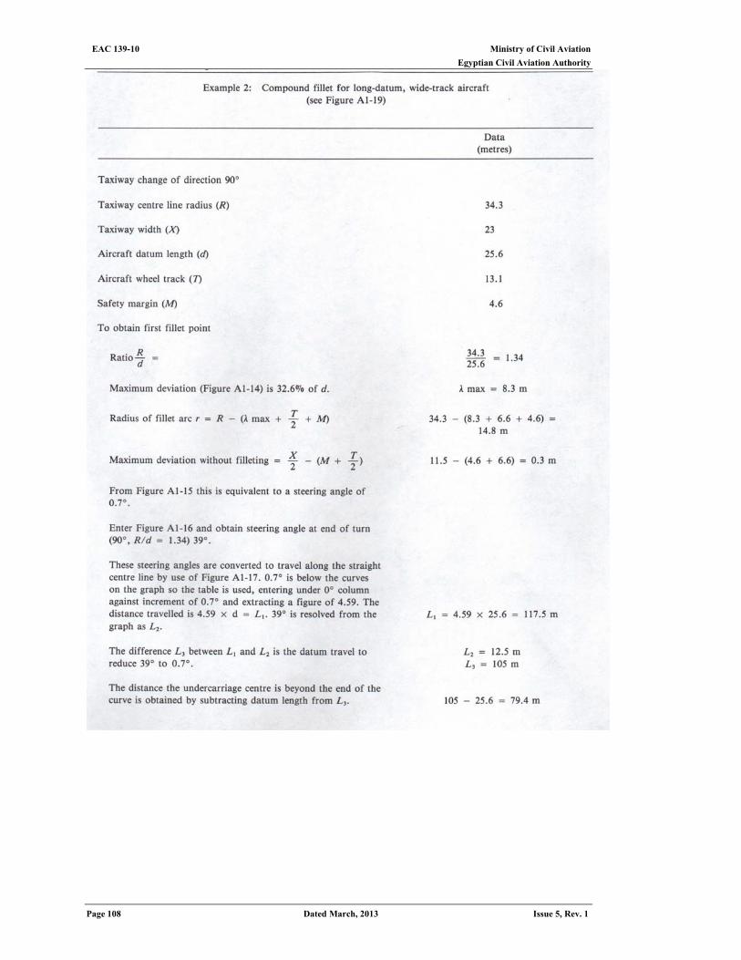
Ministry of Civil Aviation EAC 139-10 Egyptian Civil Aviation Authority
Page 108 Dated March, 2013 Issue 5, Rev. 1
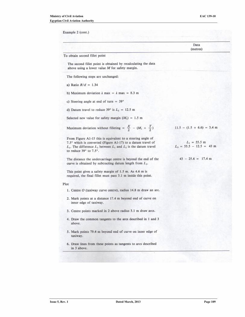
Ministry of Civil Aviation EAC 139-10
Egyptian Civil Aviation Authority
Issue 5, Rev. 1 Dated March, 2013 Page 109
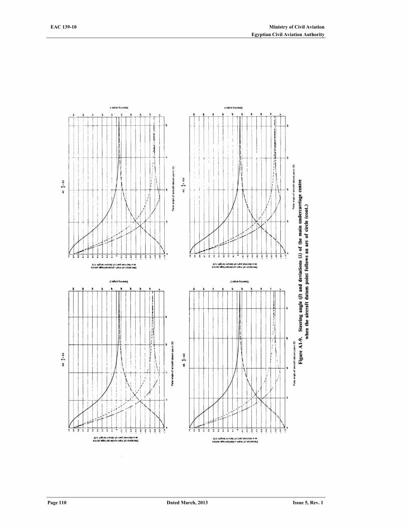
Ministry of Civil Aviation EAC 139-10 Egyptian Civil Aviation Authority
Page 110 Dated March, 2013 Issue 5, Rev. 1
Intended lift blank

Ministry of Civil Aviation EAC 139-10
Egyptian Civil Aviation Authority
Issue 5, Rev. 1 Dated March, 2013 Page 111
Intended lift blank
Ministry of Civil Aviation EAC 139-10 Egyptian Civil Aviation Authority
Page 112 Dated March, 2013 Issue 5, Rev. 1
Intended lift blank

Ministry of Civil Aviation EAC 139-10
Egyptian Civil Aviation Authority
Issue 5, Rev. 1 Dated March, 2013 Page 113
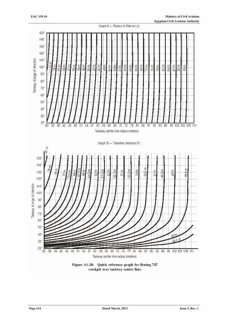
Ministry of Civil Aviation EAC 139-10 Egyptian Civil Aviation Authority
Page 114 Dated March, 2013 Issue 5, Rev. 1
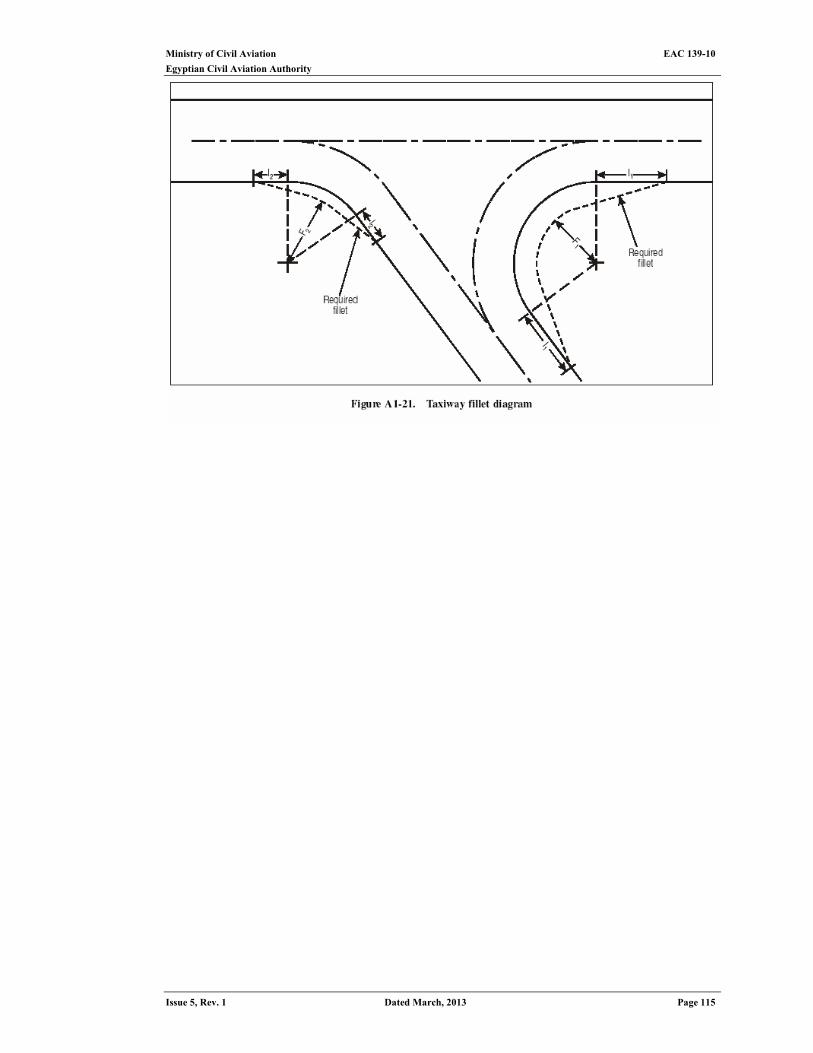
Ministry of Civil Aviation EAC 139-10
Egyptian Civil Aviation Authority
Issue 5, Rev. 1 Dated March, 2013 Page 115
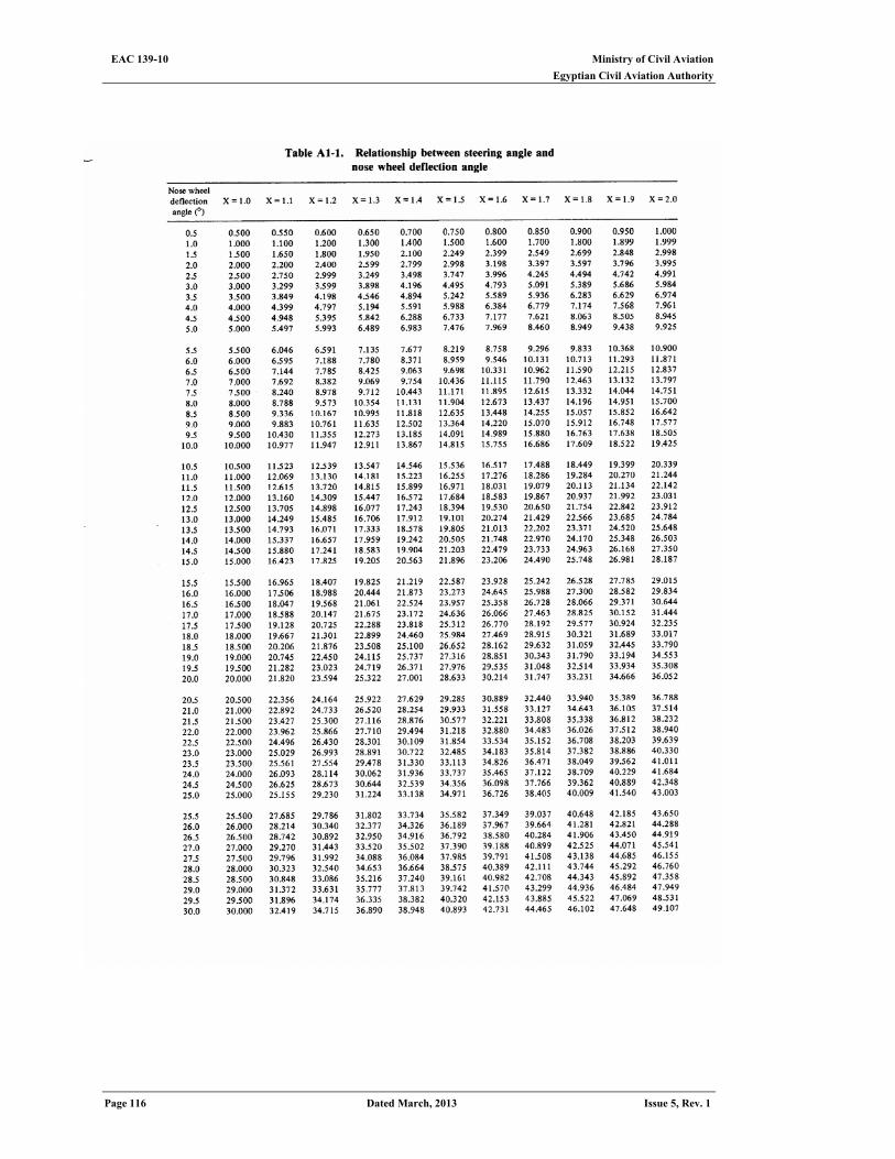
Ministry of Civil Aviation EAC 139-10 Egyptian Civil Aviation Authority
Page 116 Dated March, 2013 Issue 5, Rev. 1
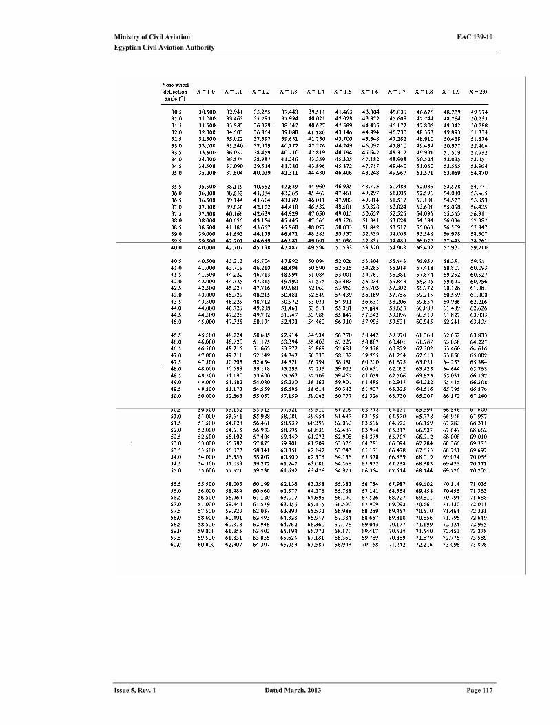
Ministry of Civil Aviation EAC 139-10
Egyptian Civil Aviation Authority
Issue 5, Rev. 1 Dated March, 2013 Page 117
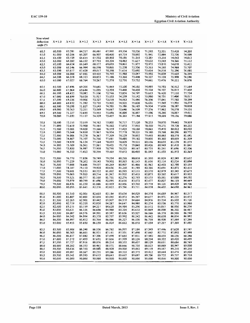
Ministry of Civil Aviation EAC 139-10 Egyptian Civil Aviation Authority
Page 118 Dated March, 2013 Issue 5, Rev. 1
Ministry of Civil Aviation EAC 139-10
Egyptian Civil Aviation Authority
Issue 5, Rev. 1 Dated March, 2013 Page 119
APPENDIX 2 Jet blast and Blast fence considerations
General
Introduction 1. “ Jet blast " and "prop wash" are terms used to describe the air currents that emanate
from the operation of jet and propeller engines respectively. The design of ground facilities, buildings and pavements must take into account the impact of the forces that result from these air movements. Prior to the introduction of jet turbine engines, very little attention was focused, when planning facilities and pavements, on the detrimental effects of propeller wash. Service and maintenance areas were sometimes equipped with fences to deflect winds because of the close aircraft spacing used in these areas, but the design of aprons and terminal buildings was generally not influenced by propeller wash considerations. The introduction of the jet engine and the technological improvements that have been made towards increasing the power and efficiency of these engines have brought about a significant increase in blast velocities and, therefore, the need to design facilities to accommodate the wind forces associated with these velocities. This appendix describes the nature of these forces in terms of their magnitude and location and presents concepts in the location and design of blast fences and pavements which may be required at aerodromes to mitigate these wind forces
Related effects
2. In addition to high wind velocities, the noise, heat and fumes from jet engine exhaust should also be anticipated when planning aerodrome facilities. However, in most cases, the areas where these related effects are detrimental to personnel or buildings are already unoccupied because of the high blast air velocities. Another problem resulting from wind forces is the potential that sand, gravel or other loose objects can become projectiles and be thrown for great distances. Care must be taken to prevent flying objects from damaging personnel, equipment, facilities and other aircraft.
Design thrust levels
3. Three levels of engine thrust are commonly used to determine the critical velocities for use in building and pavement design: idle thrust, breakaway thrust and maximum continuous thrust (take-off thrust). Nearly all facilities adjacent to aircraft movement areas will be subjected to at least idle thrust from the engines on the critical design aircraft. Breakaway thrust is the level of thrust needed to initiate aircraft taxi movement and is generally 50 to 60 per cent of maximum continuous thrust. Areas typically designed for breakaway thrust may include terminal buildings, apron and taxiway shoulders, holding bays and all pavements except for the runways. Aircraft use maximum continuous thrust during take-off, and thus the runway pavement, shoulders and ends (blast pads) would be designed for this thrust level.
Threshold velocities
4. Jet blast velocities above 56 km/hr are considered to be undesirable for personal comfort or for the operation of vehicles or other equipment on the movement area. Buildings can be designed to withstand much higher velocities, but the extra cost of construction needed to handle wind pressures above those normally used in building design may become prohibitive. Buildings are normally designed to handle winds of 130-200 km/hr, depending upon locality. If design velocities are increased above this level because of blast, then the building structural frame and architectural facades will need to be strengthened accordingly. The trade-off between increasing the cost of the building and other solutions to lower the blast velocities striking the building (such as erecting blast fences or increasing the apron size) must be examined for any given aerodrome.
Blast Velocities And Pressures
Velocity curves 5. Figures A2-1 through A2-4 present velocity curves for the Douglas DC8, Boeing B727,
Boeing B747 and Douglas DC10. Each graph has curves of velocity versus distance
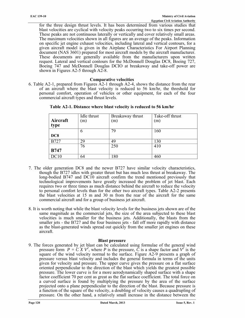
Ministry of Civil Aviation EAC 139-10 Egyptian Civil Aviation Authority
Page 120 Dated March, 2013 Issue 5, Rev. 1
for the three design thrust levels. It has been determined from various studies that blast velocities are cyclical with velocity peaks occurring two to six times per second. These peaks are not continuous laterally or vertically and cover relatively small areas. The maximum velocities shown in all figures are an average of the peaks. Information on specific jet engine exhaust velocities, including lateral and vertical contours, for a given aircraft model is given in the Airplane Characteristics For Airport Planning document (NAS 3601) prepared for most aircraft models by the aircraft manufacturer. These documents are generally available from the manufacturers upon written request. Lateral and vertical contours for the McDonnell Douglas DC8, Boeing 727, Boeing 747 and McDonnell Douglas DCIO at breakaway and take-off power are shown in Figures A2-5 through A2-8.
Comparative velocities
6. Table A2-1, prepared from Figures A2-1 through A2-4, shows the distance from the rear of an aircraft where the blast velocity is reduced to 56 km/hr, the threshold for personal comfort, operation of vehicles or other equipment, for each of the four commercial aircraft types and thrust levels.
Table A2-1. Distance where blast velocity is reduced to 56 km/hr
Take-off thrust (m)
Breakaway thrust (m)
Idle thrust (m) Aircraft
type 160 79 6
DC8
130 49 29 B727 410 250 76
B747 460 180 64 DC10
7. The older generation DC8 and the newer B727 have similar velocity characteristics, though the B727 idles with greater thrust but has much less thrust at breakaway. The long-bodied B747 and DC10 aircraft confirm the trend mentioned previously that technological improvements have greatly increased the problem of jet blast. Each requires two or three times as much distance behind the aircraft to reduce the velocity to personal comfort levels than for the other two aircraft types. Table A2-2 presents the blast velocities at 15 m and 30 m from the rear of the aircraft for the same commercial aircraft and for a group of business jet aircraft.
8. It is worth noting that while the blast velocity levels for the business jets shown are of the
same magnitude as the commercial jets, the size of the area subjected to these blast velocities is much smaller for the business jets. Additionally, the blasts from the smaller jets - the B727 and the four business jets - fall off more rapidly with distance as the blast-generated winds spread out quickly from the smaller jet engines on these aircraft.
Blast pressure
9. The forces generated by jet blast can be calculated using formulae of the general wind pressure form P = C X V2, where P is the pressure, C is a shape factor and V2 is the square of the wind velocity normal to the surface. Figure A2-9 presents a graph of pressure versus blast velocity and includes the general formula in terms of the units given for velocity and pressure. The upper curve gives the pressure on a flat surface oriented perpendicular to the direction of the blast which yields the greatest possible pressure. The lower curve is for a more aerodynamically shaped surface with a shape factor coefficient 70 per cent as great as the flat surface coefficient. The total force on a curved surface is found by multiplying the pressure by the area of the surface projected onto a plane perpendicular to the direction of the blast. Because pressure is a function of the square of the velocity, a doubling of velocity causes a quadrupling of pressure. On the other hand, a relatively small increase in the distance between the
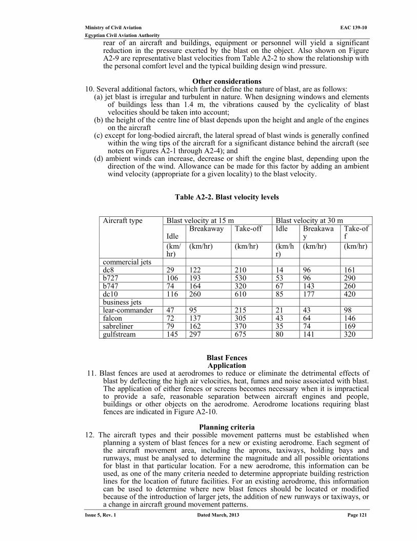
Ministry of Civil Aviation EAC 139-10
Egyptian Civil Aviation Authority
Issue 5, Rev. 1 Dated March, 2013 Page 121
rear of an aircraft and buildings, equipment or personnel will yield a significant reduction in the pressure exerted by the blast on the object. Also shown on Figure A2-9 are representative blast velocities from Table A2-2 to show the relationship with the personal comfort level and the typical building design wind pressure.
Other considerations
10. Several additional factors, which further define the nature of blast, are as follows: (a) jet blast is irregular and turbulent in nature. When designing windows and elements
of buildings less than 1.4 m, the vibrations caused by the cyclicality of blast velocities should be taken into account;
(b) the height of the centre line of blast depends upon the height and angle of the engines on the aircraft
(c) except for long-bodied aircraft, the lateral spread of blast winds is generally confined within the wing tips of the aircraft for a significant distance behind the aircraft (see notes on Figures A2-1 through A2-4); and
(d) ambient winds can increase, decrease or shift the engine blast, depending upon the direction of the wind. Allowance can be made for this factor by adding an ambient wind velocity (appropriate for a given locality) to the blast velocity.
Table A2-2. Blast velocity levels
Blast velocity at 30 m Blast velocity at 15 m Take-off
Breakaway
Idle Take-off Breakaway Idle
(km/hr) (km/hr) (km/hr)
(km/hr) (km/hr) (km/hr)
Aircraft type
commercial jets 161 96 14 210 122 29 dc8 290 96 53 530 193 106 b727 260 143 67 320 164 74 b747 420 177 85 610 260 116 dc10 business jets 98 43 21 215 95 47 lear-commander 146 64 43 305 137 72 falcon 169 74 35 370 162 79 sabreliner 320 141 80 675 297 145 gulfstream
Blast Fences Application
11. Blast fences are used at aerodromes to reduce or eliminate the detrimental effects of blast by deflecting the high air velocities, heat, fumes and noise associated with blast. The application of either fences or screens becomes necessary when it is impractical to provide a safe, reasonable separation between aircraft engines and people, buildings or other objects on the aerodrome. Aerodrome locations requiring blast fences are indicated in Figure A2-10.
Planning criteria
12. The aircraft types and their possible movement patterns must be established when planning a system of blast fences for a new or existing aerodrome. Each segment of the aircraft movement area, including the aprons, taxiways, holding bays and runways, must be analysed to determine the magnitude and all possible orientations for blast in that particular location. For a new aerodrome, this information can be used, as one of the many criteria needed to determine appropriate building restriction lines for the location of future facilities. For an existing aerodrome, this information can be used to determine where new blast fences should be located or modified because of the introduction of larger jets, the addition of new runways or taxiways, or a change in aircraft ground movement patterns.
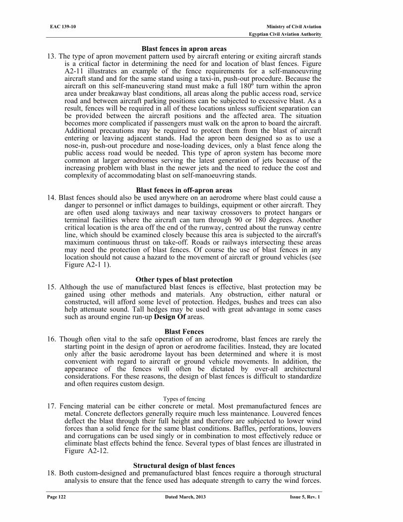
Ministry of Civil Aviation EAC 139-10 Egyptian Civil Aviation Authority
Page 122 Dated March, 2013 Issue 5, Rev. 1
Blast fences in apron areas
13. The type of apron movement pattern used by aircraft entering or exiting aircraft stands is a critical factor in determining the need for and location of blast fences. Figure A2-11 illustrates an example of the fence requirements for a self-manoeuvring aircraft stand and for the same stand using a taxi-in, push-out procedure. Because the aircraft on this self-maneuvering stand must make a full 180º turn within the apron area under breakaway blast conditions, all areas along the public access road, service road and between aircraft parking positions can be subjected to excessive blast. As a result, fences will be required in all of these locations unless sufficient separation can be provided between the aircraft positions and the affected area. The situation becomes more complicated if passengers must walk on the apron to board the aircraft. Additional precautions may be required to protect them from the blast of aircraft entering or leaving adjacent stands. Had the apron been designed so as to use a nose-in, push-out procedure and nose-loading devices, only a blast fence along the public access road would be needed. This type of apron system has become more common at larger aerodromes serving the latest generation of jets because of the increasing problem with blast in the newer jets and the need to reduce the cost and complexity of accommodating blast on self-manoeuvring stands.
Blast fences in off-apron areas
14. Blast fences should also be used anywhere on an aerodrome where blast could cause a danger to personnel or inflict damages to buildings, equipment or other aircraft. They are often used along taxiways and near taxiway crossovers to protect hangars or terminal facilities where the aircraft can turn through 90 or 180 degrees. Another critical location is the area off the end of the runway, centred about the runway centre line, which should be examined closely because this area is subjected to the aircraft's maximum continuous thrust on take-off. Roads or railways intersecting these areas may need the protection of blast fences. Of course the use of blast fences in any location should not cause a hazard to the movement of aircraft or ground vehicles (see Figure A2-1 1).
Other types of blast protection
15. Although the use of manufactured blast fences is effective, blast protection may be gained using other methods and materials. Any obstruction, either natural or constructed, will afford some level of protection. Hedges, bushes and trees can also help attenuate sound. Tall hedges may be used with great advantage in some cases such as around engine run-up Design Of areas.
Blast Fences
16. Though often vital to the safe operation of an aerodrome, blast fences are rarely the starting point in the design of apron or aerodrome facilities. Instead, they are located only after the basic aerodrome layout has been determined and where it is most convenient with regard to aircraft or ground vehicle movements. In addition, the appearance of the fences will often be dictated by over-all architectural considerations. For these reasons, the design of blast fences is difficult to standardize and often requires custom design.
Types of fencing
17. Fencing material can be either concrete or metal. Most premanufactured fences are metal. Concrete deflectors generally require much less maintenance. Louvered fences deflect the blast through their full height and therefore are subjected to lower wind forces than a solid fence for the same blast conditions. Baffles, perforations, louvers and corrugations can be used singly or in combination to most effectively reduce or eliminate blast effects behind the fence. Several types of blast fences are illustrated in Figure A2-12.
Structural design of blast fences
18. Both custom-designed and premanufactured blast fences require a thorough structural analysis to ensure that the fence used has adequate strength to carry the wind forces.
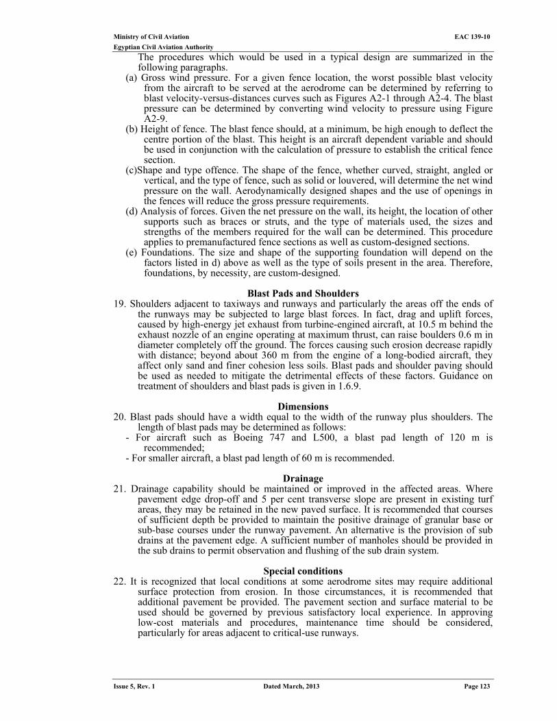
Ministry of Civil Aviation EAC 139-10
Egyptian Civil Aviation Authority
Issue 5, Rev. 1 Dated March, 2013 Page 123
The procedures which would be used in a typical design are summarized in the following paragraphs.
(a) Gross wind pressure. For a given fence location, the worst possible blast velocity from the aircraft to be served at the aerodrome can be determined by referring to blast velocity-versus-distances curves such as Figures A2-1 through A2-4. The blast pressure can be determined by converting wind velocity to pressure using Figure A2-9.
(b) Height of fence. The blast fence should, at a minimum, be high enough to deflect the centre portion of the blast. This height is an aircraft dependent variable and should be used in conjunction with the calculation of pressure to establish the critical fence section.
(c)Shape and type offence. The shape of the fence, whether curved, straight, angled or vertical, and the type of fence, such as solid or louvered, will determine the net wind pressure on the wall. Aerodynamically designed shapes and the use of openings in the fences will reduce the gross pressure requirements.
(d) Analysis of forces. Given the net pressure on the wall, its height, the location of other supports such as braces or struts, and the type of materials used, the sizes and strengths of the members required for the wall can be determined. This procedure applies to premanufactured fence sections as well as custom-designed sections.
(e) Foundations. The size and shape of the supporting foundation will depend on the factors listed in d) above as well as the type of soils present in the area. Therefore, foundations, by necessity, are custom-designed.
Blast Pads and Shoulders
19. Shoulders adjacent to taxiways and runways and particularly the areas off the ends of the runways may be subjected to large blast forces. In fact, drag and uplift forces, caused by high-energy jet exhaust from turbine-engined aircraft, at 10.5 m behind the exhaust nozzle of an engine operating at maximum thrust, can raise boulders 0.6 m in diameter completely off the ground. The forces causing such erosion decrease rapidly with distance; beyond about 360 m from the engine of a long-bodied aircraft, they affect only sand and finer cohesion less soils. Blast pads and shoulder paving should be used as needed to mitigate the detrimental effects of these factors. Guidance on treatment of shoulders and blast pads is given in 1.6.9.
Dimensions
20. Blast pads should have a width equal to the width of the runway plus shoulders. The length of blast pads may be determined as follows:
- For aircraft such as Boeing 747 and L500, a blast pad length of 120 m is recommended;
- For smaller aircraft, a blast pad length of 60 m is recommended.
Drainage 21. Drainage capability should be maintained or improved in the affected areas. Where
pavement edge drop-off and 5 per cent transverse slope are present in existing turf areas, they may be retained in the new paved surface. It is recommended that courses of sufficient depth be provided to maintain the positive drainage of granular base or sub-base courses under the runway pavement. An alternative is the provision of sub drains at the pavement edge. A sufficient number of manholes should be provided in the sub drains to permit observation and flushing of the sub drain system.
Special conditions
22. It is recognized that local conditions at some aerodrome sites may require additional surface protection from erosion. In those circumstances, it is recommended that additional pavement be provided. The pavement section and surface material to be used should be governed by previous satisfactory local experience. In approving low-cost materials and procedures, maintenance time should be considered, particularly for areas adjacent to critical-use runways.
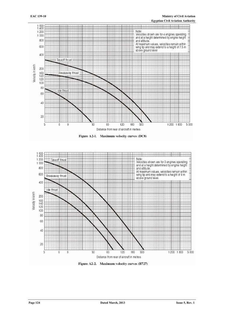
Ministry of Civil Aviation EAC 139-10 Egyptian Civil Aviation Authority
Page 124 Dated March, 2013 Issue 5, Rev. 1
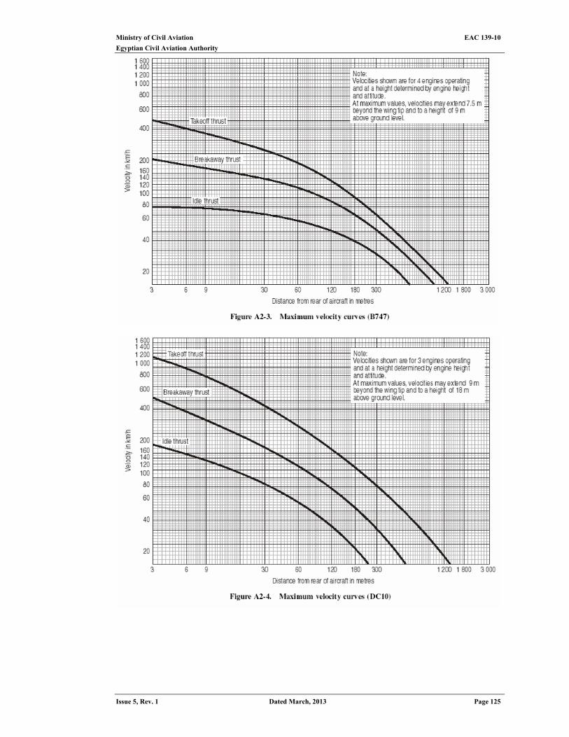
Ministry of Civil Aviation EAC 139-10
Egyptian Civil Aviation Authority
Issue 5, Rev. 1 Dated March, 2013 Page 125
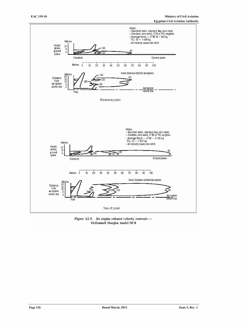
Ministry of Civil Aviation EAC 139-10 Egyptian Civil Aviation Authority
Page 126 Dated March, 2013 Issue 5, Rev. 1
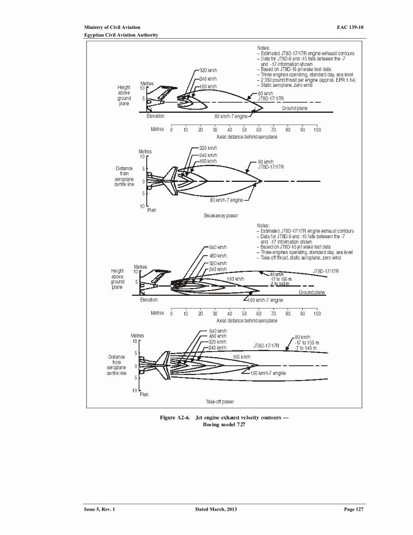
Ministry of Civil Aviation EAC 139-10
Egyptian Civil Aviation Authority
Issue 5, Rev. 1 Dated March, 2013 Page 127
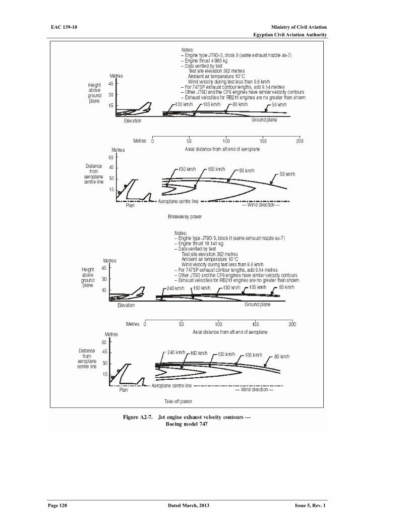
Ministry of Civil Aviation EAC 139-10 Egyptian Civil Aviation Authority
Page 128 Dated March, 2013 Issue 5, Rev. 1
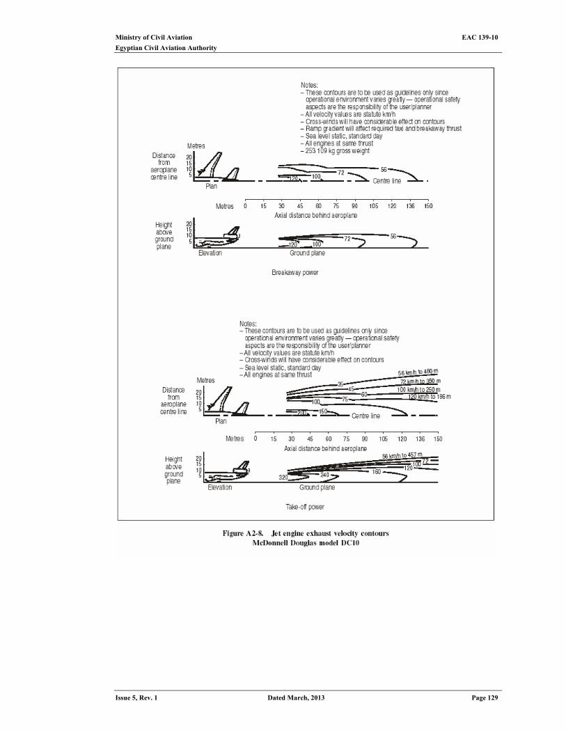
Ministry of Civil Aviation EAC 139-10
Egyptian Civil Aviation Authority
Issue 5, Rev. 1 Dated March, 2013 Page 129
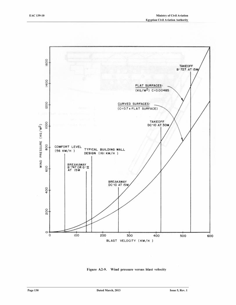
Ministry of Civil Aviation EAC 139-10 Egyptian Civil Aviation Authority
Page 130 Dated March, 2013 Issue 5, Rev. 1
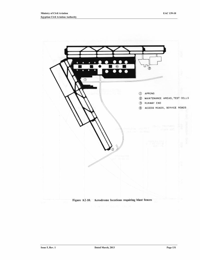
Ministry of Civil Aviation EAC 139-10
Egyptian Civil Aviation Authority
Issue 5, Rev. 1 Dated March, 2013 Page 131

Ministry of Civil Aviation EAC 139-10 Egyptian Civil Aviation Authority
Page 132 Dated March, 2013 Issue 5, Rev. 1
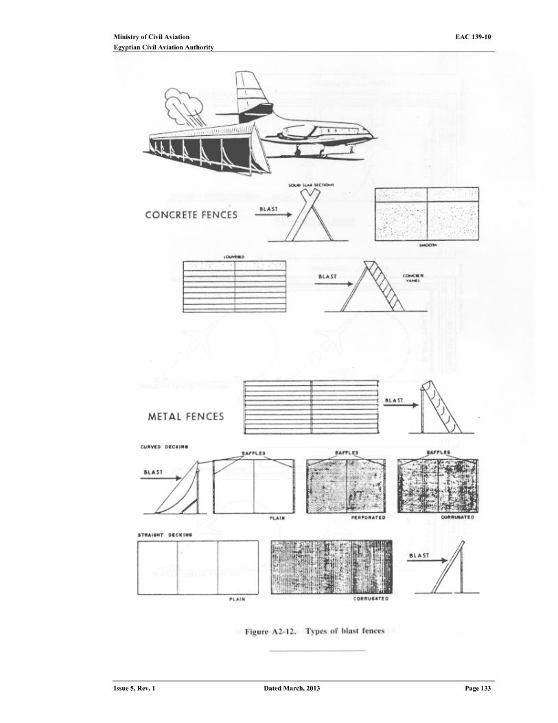
Ministry of Civil Aviation EAC 139-10
Egyptian Civil Aviation Authority
Issue 5, Rev. 1 Dated March, 2013 Page 133
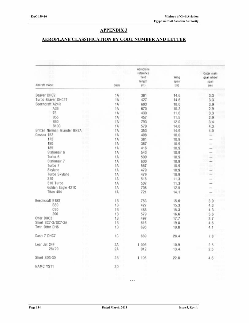
Ministry of Civil Aviation EAC 139-10 Egyptian Civil Aviation Authority
Page 134 Dated March, 2013 Issue 5, Rev. 1
APPENDIX 3
AEROPLANE CLASSIFICATION BY CODE NUMBER AND LETTER
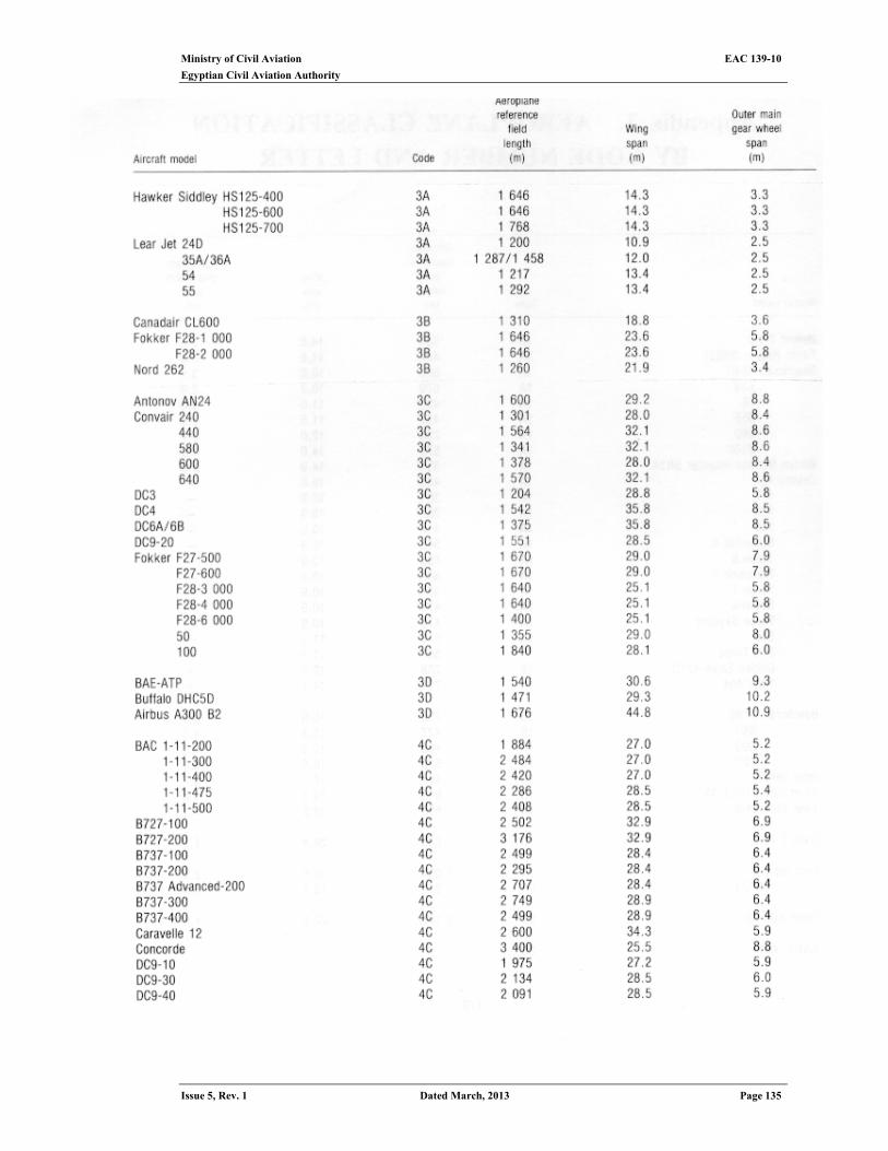
Ministry of Civil Aviation EAC 139-10
Egyptian Civil Aviation Authority
Issue 5, Rev. 1 Dated March, 2013 Page 135
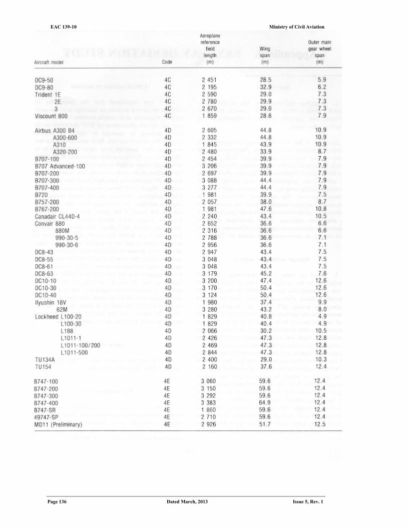
Ministry of Civil Aviation EAC 139-10 Egyptian Civil Aviation Authority
Page 136 Dated March, 2013 Issue 5, Rev. 1
Ministry of Civil Aviation EAC 139-10
Egyptian Civil Aviation Authority
Issue 5, Rev. 1 Dated March, 2013 Page 137
APPENDIX 4 Taxiway deviation study
Introduction
1. A taxiway deviation study was carried out by British Airports Public Ltd. at London Heathrow Airport. Over 77 000 aircraft taxiing movements in all weather conditions were recorded. The purpose of the study was to show that pilots do not deviate significantly from the centre line when taxiing. The analysis of the data had two objectives. The primary objective was to estimate the probability of two Boeing 747-400 aircraft colliding wing tips when passing each other on parallel taxiways. The secondary objective was to estimate the expected number of years that would elapse before this collision occurred. The study also attempted to assess the adequacy of the separation distances between parallel taxiway runways and between taxiways and objects, as recommended in ECAR 139, Table 3-1.
Straight sections of taxiway
2. Based on some 2 000 observations of B747 deviations on the straight sections of taxiways, the study concluded that the probability of two B747-400 aircraft colliding when passing each other on parallel taxiways is around 10-8, i.e. I in 100 million. This assumes that the taxiway centre lines are 76.5 m apart and that the aircraft have a wing span of 65 m. Upon analysing the data in the large data base which had been established, there was ample evidence to indicate that taxiing aircraft do not deviate from taxiway centre lines to any great degree. The data also provided an estimate of the number of occasions per year that two standard B747s pass each other on Heathrow's parallel taxiways. This would be about 80 occasions per year out of around 34 000 B747 air transport movements. This figure was considered low because, in the majority of cases, the aircraft would be moving in the same direction through the taxiway system. Departing aircraft use one runway and arriving aircraft use another; their paths rarely overlap. Figure A4-1 shows the distribution of deviations upon which the analysis is based.
Curved sections of taxiways
3. It was considered that the probability of collision on curved sections on taxiways is of the same order of magnitude as in straight sections, i.e. 10-8. There were not enough observations of B747 deviations on the curved sections of taxiways to repeat the analysis detailed for straight sections. Data were collected at two locations. Data from the inner curve proved not to be useful because there was a large paved area to the inside of it which pilots tended to cut across. The number of observations on the outer curve was low because several months of maintenance work had closed that part of the taxiway. Figure A4-2 shows the distribution of the 185 B747 deviations observed on the outer curve. The negative numbers are deviations from the centre line towards the inside of the curve. This is in a different form to Figure A4-1 which shows only absolute deviations. Figure A4-2 shows that almost all aircraft main wheels cut across the corner. For a collision to occur at a curved part of the parallel taxiway, the outer aircraft must deviate to the inside and the inner aircraft must deviate to the outside. Figure A4-2 shows that the latter is very unlikely to happen. The over-all distribution suggests that the collision probability would be similar to that of straight sections, i.e. 10 -8. Curved sections of taxiways were regarded as less of a problem than straight sections of taxiways since there will always be fewer curved elements in a given taxiway layout. Thus, the chance that two aircraft pass on a curved section is much less than on a straight section.
Speed effect 4. The analysis showed that an aircraft's speed does not effect its lateral deviation.
Bad weather effect 5. No link could be established between bad weather and large taxiway deviations. During
the data collection period, most weather conditions were encountered including snow fall, heavy rain, strong winds and visibility reduced to 1 000 m.
Ministry of Civil Aviation EAC 139-10 Egyptian Civil Aviation Authority
Page 138 Dated March, 2013 Issue 5, Rev. 1
Statistics for all aircraft 6. Tables A4-1 and A4-2 show summary statistics for all aircraft on the straight and the
outer curved sections of taxiways, respectively.
Amsterdam Schiphol study 7. A taxiway centre line deviation test was conducted at Amsterdam’s Schiphol Airport
from October 1988 to September 1991. Over 9 000 ICAO Category E aircraft (mostly B747) taxiing movements were recorded over the three-year span. Using infra-red beams, data were collected for a straight and a curved section of the taxiway. The taxiway width was 22.9 m. The curved section had a centre line radius of 55 m and a turn of 120 degrees. Centre line lighting was provided on both sections of taxiway.
8. The data were used by the Boeing Company to accomplish a statistical analysis of
aircraft landing gear deviations. The purpose of the study was to estimate the extreme probabilities of gear deviations (those well outside the range of observed deviations), as well as to obtain estimates of the probability of wing tip contact between two aircraft on parallel taxiways.
9. A summary of statistics for the taxiway data is provided in Table A4-3. The data from
the curved section indicates that pilots of large aircraft use a judgmental over steer technique to insure that the main landing gear remains on the pavement.
Deviation probability estimates
10. The fact that data do not exist for gear deviations greater than 3.54 m on straight taxiways necessitates extrapolation for probabilities for greater deviations.
Wing tip contact probability
11. Using the extrapolated probabilities of extreme main gear deviations, the probabilities of wing tip-to-wing tip contact between two aircraft on parallel taxiways were calculated. These probabilities depend on the probability distribution of the sum of the two taxiway deviations, noting that two simultaneous deviations on parallel taxiways are statistically independent.
12. Table A4-4 summarizes estimates of required taxiway separations and estimated 90 per cent upper bounds for various wingspan probabilities.
Estimates of required taxiway separations
13. As an example, the mean estimate of taxiway separation required for a probability of a 10–9 wing tip contact between two aircraft with 73.2 m wingspans is 80.5 m.
Conditions affecting deviation
14. Some conditions that were recorded with the deviation were the year, month, day, time, taxi speed and direction. The variability of deviations was not affected by these factors. For example, the standard deviation on the straight section is 68.8 cm. The standard deviation is 67.1 cm after removing any systematic deviation due to taxi direction, season and time of day. Thus, the practical significance (in contrast to the statistical significance) of these effects may be minimal.
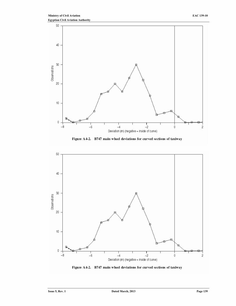
Ministry of Civil Aviation EAC 139-10
Egyptian Civil Aviation Authority
Issue 5, Rev. 1 Dated March, 2013 Page 139

Ministry of Civil Aviation EAC 139-10 Egyptian Civil Aviation Authority
Page 140 Dated March, 2013 Issue 5, Rev. 1
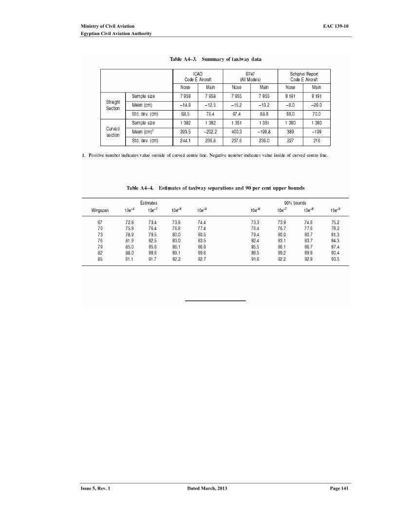
Ministry of Civil Aviation EAC 139-10
Egyptian Civil Aviation Authority
Issue 5, Rev. 1 Dated March, 2013 Page 141
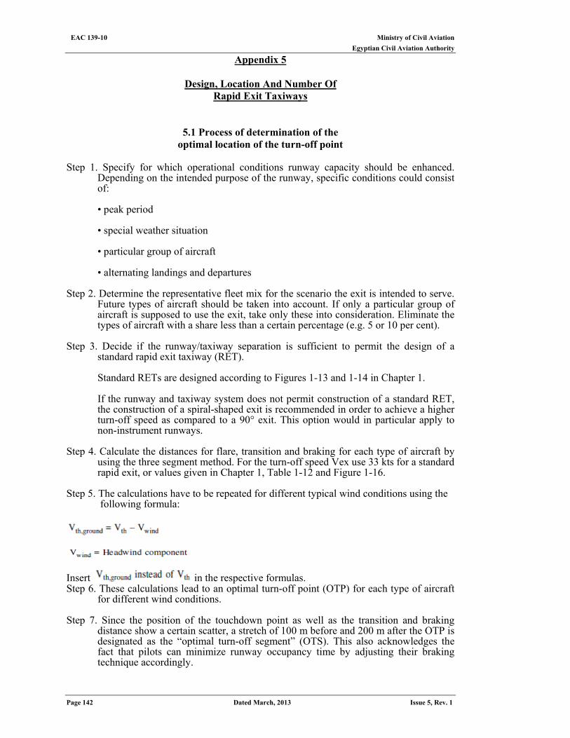
Ministry of Civil Aviation EAC 139-10 Egyptian Civil Aviation Authority
Page 142 Dated March, 2013 Issue 5, Rev. 1
Appendix 5
Design, Location And Number Of Rapid Exit Taxiways
5.1 Process of determination of the optimal location of the turn-off point
Step 1. Specify for which operational conditions runway capacity should be enhanced.
Depending on the intended purpose of the runway, specific conditions could consist of:
• peak period • special weather situation • particular group of aircraft • alternating landings and departures
Step 2. Determine the representative fleet mix for the scenario the exit is intended to serve.
Future types of aircraft should be taken into account. If only a particular group of aircraft is supposed to use the exit, take only these into consideration. Eliminate the types of aircraft with a share less than a certain percentage (e.g. 5 or 10 per cent).
Step 3. Decide if the runway/taxiway separation is sufficient to permit the design of a
standard rapid exit taxiway (RET).
Standard RETs are designed according to Figures 1-13 and 1-14 in Chapter 1.
If the runway and taxiway system does not permit construction of a standard RET, the construction of a spiral-shaped exit is recommended in order to achieve a higher turn-off speed as compared to a 90° exit. This option would in particular apply to non-instrument runways.
Step 4. Calculate the distances for flare, transition and braking for each type of aircraft by
using the three segment method. For the turn-off speed Vex use 33 kts for a standard rapid exit, or values given in Chapter 1, Table 1-12 and Figure 1-16.
Step 5. The calculations have to be repeated for different typical wind conditions using the
following formula:
Insert in the respective formulas. Step 6. These calculations lead to an optimal turn-off point (OTP) for each type of aircraft
for different wind conditions. Step 7. Since the position of the touchdown point as well as the transition and braking
distance show a certain scatter, a stretch of 100 m before and 200 m after the OTP is designated as the “optimal turn-off segment” (OTS). This also acknowledges the fact that pilots can minimize runway occupancy time by adjusting their braking technique accordingly.
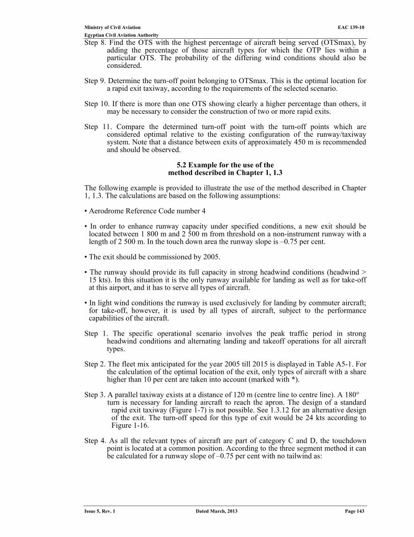
Ministry of Civil Aviation EAC 139-10
Egyptian Civil Aviation Authority
Issue 5, Rev. 1 Dated March, 2013 Page 143
Step 8. Find the OTS with the highest percentage of aircraft being served (OTSmax), by adding the percentage of those aircraft types for which the OTP lies within a particular OTS. The probability of the differing wind conditions should also be considered.
Step 9. Determine the turn-off point belonging to OTSmax. This is the optimal location for
a rapid exit taxiway, according to the requirements of the selected scenario. Step 10. If there is more than one OTS showing clearly a higher percentage than others, it
may be necessary to consider the construction of two or more rapid exits. Step 11. Compare the determined turn-off point with the turn-off points which are
considered optimal relative to the existing configuration of the runway/taxiway system. Note that a distance between exits of approximately 450 m is recommended and should be observed.
5.2 Example for the use of the
method described in Chapter 1, 1.3 The following example is provided to illustrate the use of the method described in Chapter 1, 1.3. The calculations are based on the following assumptions: • Aerodrome Reference Code number 4 • In order to enhance runway capacity under specified conditions, a new exit should be
located between 1 800 m and 2 500 m from threshold on a non-instrument runway with a length of 2 500 m. In the touch down area the runway slope is –0.75 per cent.
• The exit should be commissioned by 2005. • The runway should provide its full capacity in strong headwind conditions (headwind >
15 kts). In this situation it is the only runway available for landing as well as for take-off at this airport, and it has to serve all types of aircraft.
• In light wind conditions the runway is used exclusively for landing by commuter aircraft;
for take-off, however, it is used by all types of aircraft, subject to the performance capabilities of the aircraft.
Step 1. The specific operational scenario involves the peak traffic period in strong
headwind conditions and alternating landing and takeoff operations for all aircraft types.
Step 2. The fleet mix anticipated for the year 2005 till 2015 is displayed in Table A5-1. For
the calculation of the optimal location of the exit, only types of aircraft with a share higher than 10 per cent are taken into account (marked with *).
Step 3. A parallel taxiway exists at a distance of 120 m (centre line to centre line). A 180°
turn is necessary for landing aircraft to reach the apron. The design of a standard rapid exit taxiway (Figure 1-7) is not possible. See 1.3.12 for an alternative design of the exit. The turn-off speed for this type of exit would be 24 kts according to Figure 1-16.
Step 4. As all the relevant types of aircraft are part of category C and D, the touchdown
point is located at a common position. According to the three segment method it can be calculated for a runway slope of –0.75 per cent with no tailwind as:
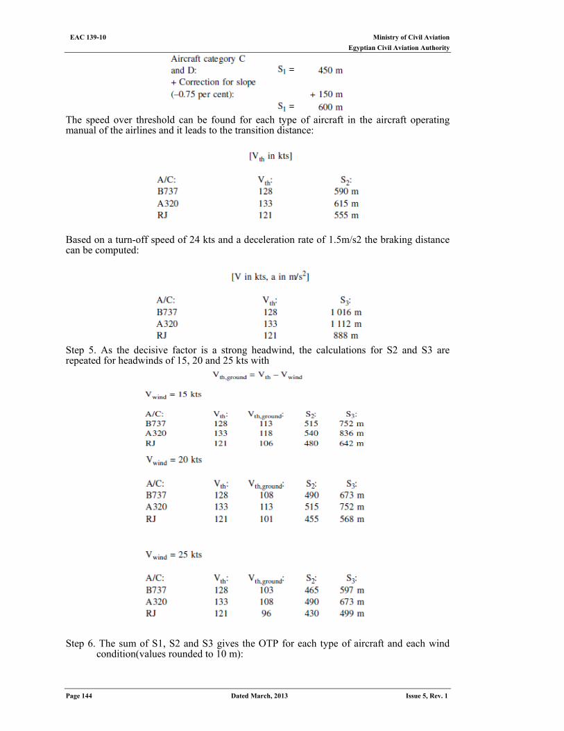
Ministry of Civil Aviation EAC 139-10 Egyptian Civil Aviation Authority
Page 144 Dated March, 2013 Issue 5, Rev. 1
The speed over threshold can be found for each type of aircraft in the aircraft operating manual of the airlines and it leads to the transition distance:
Based on a turn-off speed of 24 kts and a deceleration rate of 1.5m/s2 the braking distance can be computed:
Step 5. As the decisive factor is a strong headwind, the calculations for S2 and S3 are repeated for headwinds of 15, 20 and 25 kts with
Step 6. The sum of S1, S2 and S3 gives the OTP for each type of aircraft and each wind
condition(values rounded to 10 m):
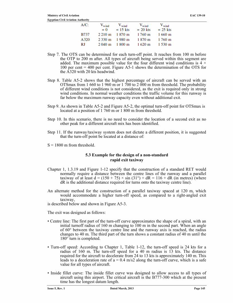
Ministry of Civil Aviation EAC 139-10
Egyptian Civil Aviation Authority
Issue 5, Rev. 1 Dated March, 2013 Page 145
Step 7. The OTS can be determined for each turn-off point. It reaches from 100 m before the OTP to 200 m after. All types of aircraft being served within this segment are added. The maximum possible value for the four different wind conditions is 4 × 100 per cent = 400 per cent. Figure A5-1 shows the determination of the OTS for the A320 with 20 kts headwind.
Step 8. Table A5-2 shows that the highest percentage of aircraft can be served with an
OTSmax from 1 660 to 1 960 m or 1 700 to 2 000 m from threshold. The probability of different wind conditions is not considered, as the exit is required only in strong wind conditions. In normal weather conditions the traffic volume for this runway is far below the maximum runway capacity even without additional exit.
Step 9. As shown in Table A5-2 and Figure A5-2, the optimal turn-off point for OTSmax is
located at a position of 1 760 m or 1 800 m from threshold.
Step 10. In this scenario, there is no need to consider the location of a second exit as no other peak for a different aircraft mix has been identified.
Step 11. If the runway/taxiway system does not dictate a different position, it is suggested
that the turn-off point be located at a distance of: S = 1800 m from threshold.
5.3 Example for the design of a non-standard rapid exit taxiway
Chapter 1, 1.3.19 and Figure 1-12 specify that the construction of a standard RET would
normally require a distance between the centre lines of the runway and a parallel taxiway of at least d = (150 + 75) × sin (31°) + dR = 116 + dR (in metres) (where dR is the additional distance required for turns onto the taxiway centre line).
An alternate method for the construction of a parallel taxiway spaced at 120 m, which
would accommodate a higher turn-off speed, as compared to a right-angled exit taxiway,
is described below and shown in Figure A5-3. The exit was designed as follows: • Centre line: The first part of the turn-off curve approximates the shape of a spiral, with an
initial turnoff radius of 160 m changing to 100 m in the second part. When an angle of 60° between the taxiway centre line and the runway axis is reached, the radius changes to 40 m. The third part of the turn shows a constant radius of 40 m until the 180° turn is completed.
• Turn-off speed: According to Chapter 1, Table 1-12, the turn-off speed is 24 kts for a
radius of 160 m. The turn-off speed for a 40 m radius is 13 kts. The distance required for the aircraft to decelerate from 24 to 13 kts is approximately 140 m. This leads to a deceleration rate of a = 0.4 m/s2 along the turn-off curve, which is a safe value for all types of aircraft.
• Inside fillet curve: The inside fillet curve was designed to allow access to all types of
aircraft using this airport. The critical aircraft is the B777-300 which at the present time has the longest datum length.
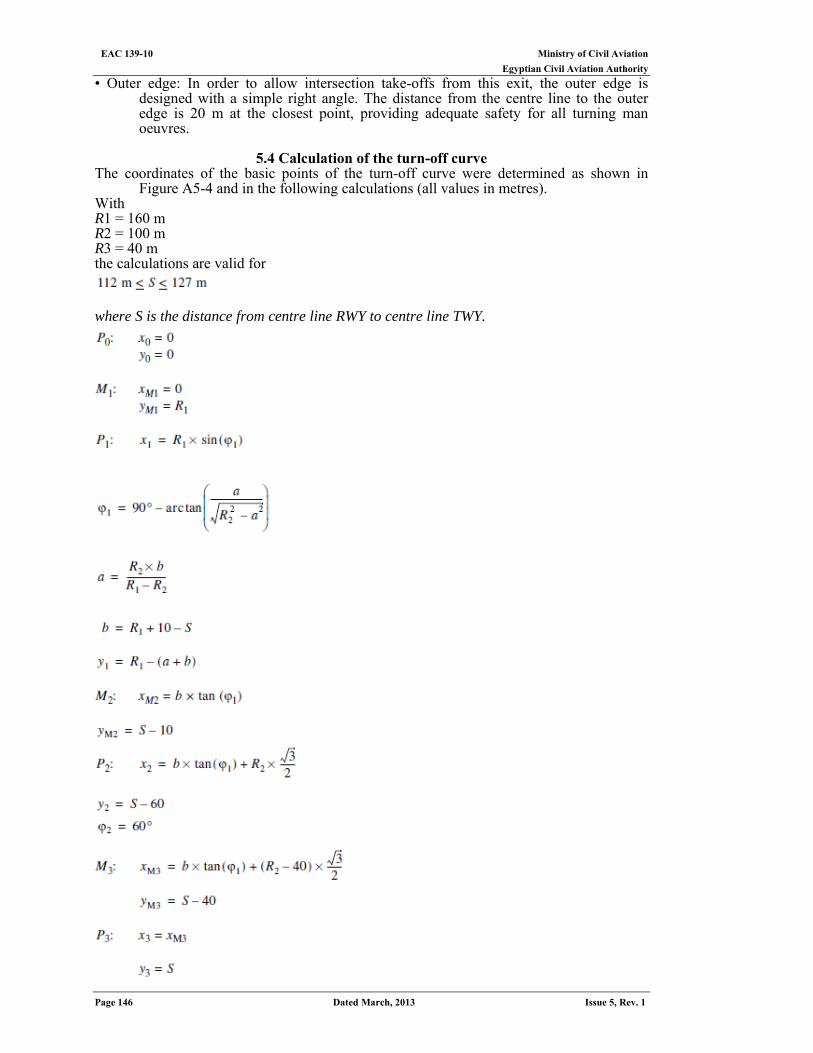
Ministry of Civil Aviation EAC 139-10 Egyptian Civil Aviation Authority
Page 146 Dated March, 2013 Issue 5, Rev. 1
• Outer edge: In order to allow intersection take-offs from this exit, the outer edge is designed with a simple right angle. The distance from the centre line to the outer edge is 20 m at the closest point, providing adequate safety for all turning man oeuvres.
5.4 Calculation of the turn-off curve
The coordinates of the basic points of the turn-off curve were determined as shown in Figure A5-4 and in the following calculations (all values in metres).
With R1 = 160 m R2 = 100 m R3 = 40 m the calculations are valid for
where S is the distance from centre line RWY to centre line TWY.
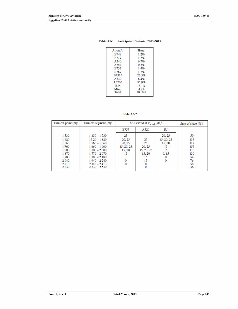
Ministry of Civil Aviation EAC 139-10
Egyptian Civil Aviation Authority
Issue 5, Rev. 1 Dated March, 2013 Page 147
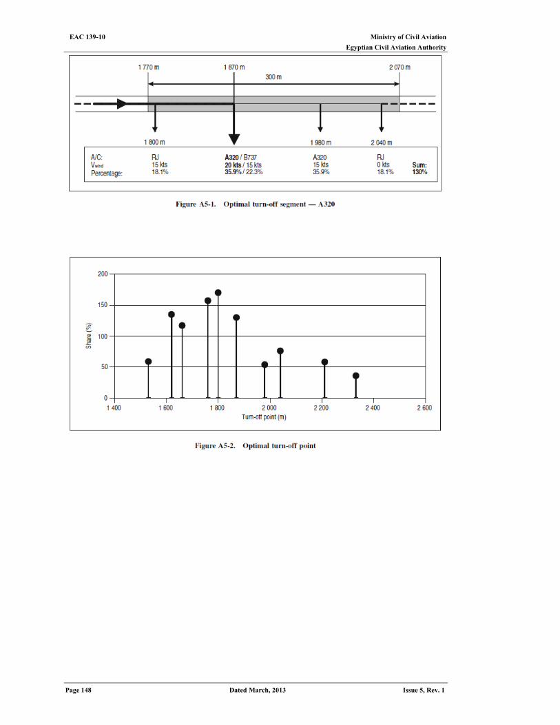
Ministry of Civil Aviation EAC 139-10 Egyptian Civil Aviation Authority
Page 148 Dated March, 2013 Issue 5, Rev. 1
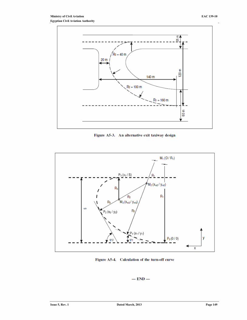
Ministry of Civil Aviation EAC 139-10
Egyptian Civil Aviation Authority
Issue 5, Rev. 1 Dated March, 2013 Page 149