Embed Size (px)
Citation preview
EEaaggllee EEqquuiippmmeenntt FFPP SSeerriieess LLiiffttss
Copyright © 2002 Eagle Equipment, Inc. 1-800-336-2776 FP-1 www.eagleequip.com
Table of Contents
INTRODUCTION .....................................................................................................2
WELCOME TO EAGLE EQUIPMENT...................................................................2
HOW TO USE THIS MANUAL...............................................................................2
WHAT TO DO IF YOU NEED HELP .....................................................................2
LIFT SPECIFICATIONS ..........................................................................................3
SAFETY.....................................................................................................................4
A NOTE ABOUT HYDRAULIC FLUID.................................................................4
TO OBTAIN THE BEST INSTALLATION ............................................................4
UNPACKING YOUR LIFT ......................................................................................5
INVENTORY YOUR LIFT ......................................................................................8
THE MAJOR COMPONENTS OF YOUR FP SERIES LIFT ..............................10
ASSEMBLING YOUR LIFT ..................................................................................11
INSTALL THE HYDRAULICS .............................................................................20
FINAL ADJUSTMENTS ........................................................................................23
BLEED THE HYDRAULIC SYSTEM ..................................................................24
LEVEL THE LIFT...................................................................................................24
INSTALL DRIVE ON RAMPS ..............................................................................25
ROLLING AIR JACK INSTALLATION (OPTIONAL) .......................................26
ROLLING AIR JACK OPERATION (OPTIONAL)..............................................29
OPERATION OF YOUR LIFT...............................................................................30
MAINTENANCE ....................................................................................................32
INDEX .....................................................................................................................33
EEaaggllee EEqquuiippmmeenntt FFPP SSeerriieess LLiiffttss
Copyright © 2002 Eagle Equipment, Inc. 1-800-336-2776 FP-2 www.eagleequip.com
Introduction
Welcome to Eagle Equipment Congratulations on your purchase of an Eagle Equipment FP series four post lift! In the pages that follow, you will find information on how to unpack, assemble, operate, and maintain your lift. Please take the time to read this manual thoroughly to make sure that you know what will be required of you, your assistants, and the area in which your lift is being installed.
How To Use This Manual We at Eagle Equipment have provided detailed step by step documentation and illustrations to guide you through the process of installing and operating your new lift. Please take the time now to read through this manual - a greater understanding of the procedures described here will go a long way towards easy installation and safe, reliable operation of your lift.
This manual is arranged to guide you throughout the entire installation process from the time you receive and unpack your lift, through assembly and operation, to the installation of accessories. The procedures are broken down into sections as listed in the Table of Contents. The text of each step in a procedure always follows the photographs or diagrams illustrating that step.
What To Do If You Need Help We’ve tried to do our very best to provide complete and detailed information so that your installation experience is free of problems; however, sometimes you just need a little help. If you should run into any problems installing or operating your new lift, or have questions on some of the parts, feel free to contact our service department at (800) 535-0016 or via email at [email protected]. © EAGLE EQUIPMENT, INC. P.O. Box 420 Chartley MA 02712-0420 FP Series Installation Guide January 2002 Manual produced by: Tech Research Group, Inc. 2377 Pawtucket Ave East Providence, RI 02914 Tel: (401) 434-4680 www.techresearchgroup.com
EE
aaggll ee
EEqq
uuii pp
mmeenntt
FFPP
SSeerr ii
eess LL
ii fftt ss
Cop
yrig
ht ©
200
2 E
agle
Equ
ipm
ent,
Inc.
1-
800-
336-
2776
FP
-3
ww
w.e
agle
equi
p.co
m
Lif
t S
pe
cif
ica
tio
ns
Spec
ifica
tions
F
P-12
F
P-15
S-14
F
P-15
L-14
F
P-15
S-22
F
P-15
L-22
F
P-15
AF
P-27
-24
F
P-27
-24
L M
axim
um
Cap
acity
12
,000
15
,000
15
,000
15
,000
15
,000
15
,000
27
,000
27
,000
Ove
rall
Leng
th
(with
out
ram
ps)
15’6
” 15
’6”
17’2
” 15
’6”
17’2
” 17
’2”
21’6
” 26
’6”
Ove
rall
Leng
th
(with
ram
ps)
18’6
” 18
’6”
20’2
” 18
’6”
20’2
” 23
’2”
24’6
” 29
’6”
Ove
rall
Wid
th
10’4
” 11
’4”
11’4
” 11
’4”
11’4
” 11
’4”
11’1
1”
11’1
1”
Lifti
ng H
eigh
t 72
” 72
” 72
” 72
” 72
” 72
” 60
” 60
” M
axim
um
Whe
elba
se (s
ee
Not
e A
bel
ow)
172”
17
2”
192”
17
2”
192”
20
0”
240”
30
0”
Trac
k W
idth
14
” 14
” 14
” 22
” 22
” 22
” 24
” 24
” R
ate
of li
ft to
full
heig
ht
50
seco
nds
50
seco
nds
50
seco
nds
50
seco
nds
50
seco
nds
50
seco
nds
120
seco
nds
120
seco
nds
Max
imum
cl
eara
nce
betw
een
colu
mns
9’
10’
10’
10’
10’
10’
10’
10’
Ship
ping
wei
ght
2,20
0 2,
650
2,80
0 2,
984
3,14
7 4,
083
5,81
1 6,
973
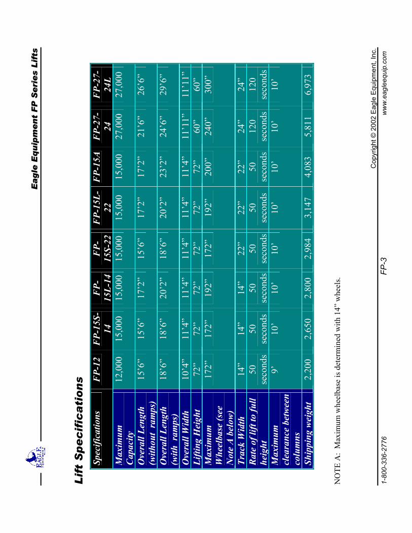
NO
TE A
: M
axim
um w
heel
base
is d
eter
min
ed w
ith 1
4” w
heel
s.
EEaaggllee EEqquuiippmmeenntt FFPP SSeerriieess LLiiffttss
Copyright © 2002 Eagle Equipment, Inc. 1-800-336-2776 FP-4 www.eagleequip.com
Safety Wear work gloves and safety glasses during the installation process, and avoid alcohol when installing or operating your lift. Ensure that you have the proper tools, installation equipment, and manpower to complete installation of your FP series lift.
A Note about Hydraulic Fluid Use ONLY AW-32 or ISO-32 hydraulic oil for your lift. DO NOT USE DEXRON®. Use of Dexron® will damage the seals in the lift hydraulic system and shorten the usable life of all hydraulic components. Use of Dexron® or any other fluids other than AW-32 or ISO-32 hydraulic fluid will void your warranty.
To obtain the best installation Your installation area should be level, with a minimum of 4”, 3000 psi steel reinforced concrete. If your installation area is not level, spacing shims may be ordered from Eagle lift at additional cost.
EEaaggllee EEqquuiippmmeenntt FFPP SSeerriieess LLiiffttss
Copyright © 2002 Eagle Equipment, Inc. 1-800-336-2776 FP-5 www.eagleequip.com
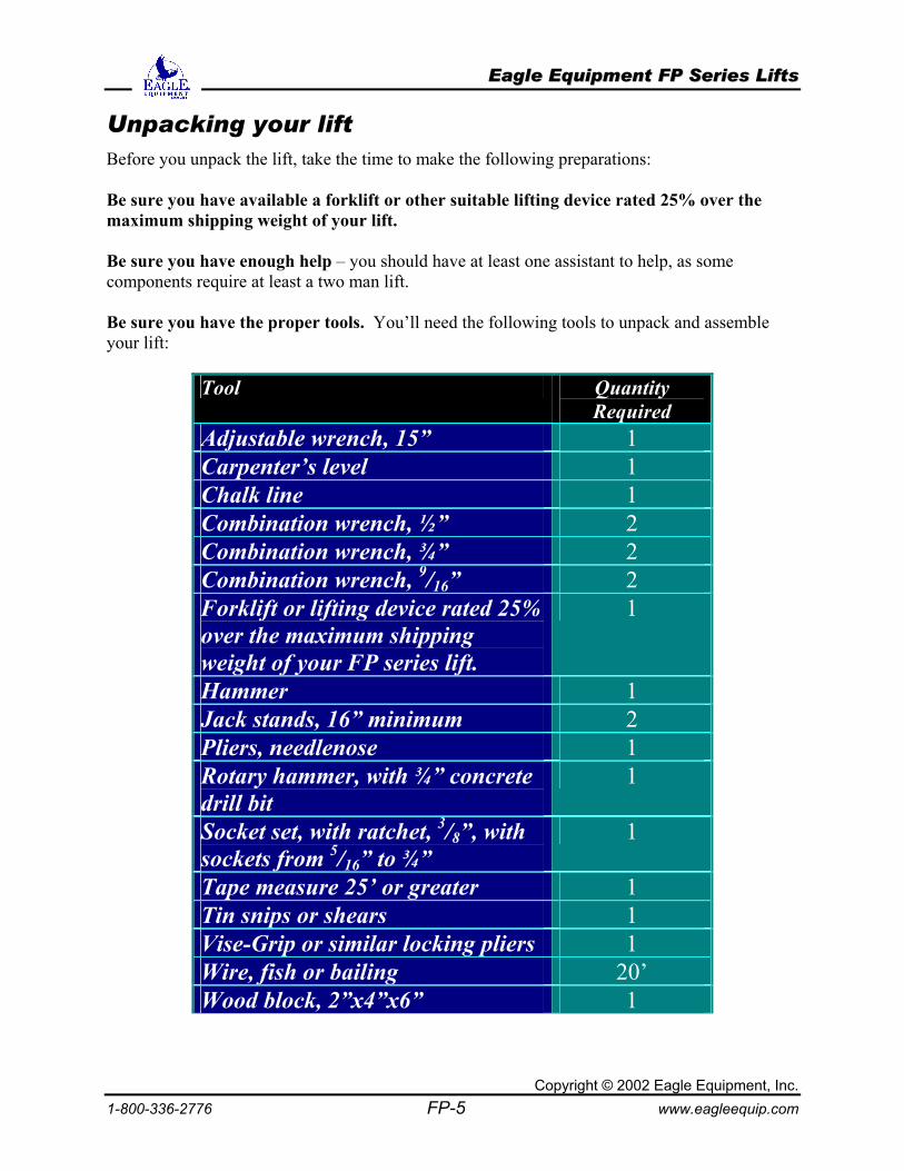
Unpacking your lift Before you unpack the lift, take the time to make the following preparations: Be sure you have available a forklift or other suitable lifting device rated 25% over the maximum shipping weight of your lift. Be sure you have enough help – you should have at least one assistant to help, as some components require at least a two man lift. Be sure you have the proper tools. You’ll need the following tools to unpack and assemble your lift:
Tool Quantity Required
Adjustable wrench, 15” 1 Carpenter’s level 1 Chalk line 1 Combination wrench, ½” 2 Combination wrench, ¾” 2 Combination wrench, 9/16” 2 Forklift or lifting device rated 25% over the maximum shipping weight of your FP series lift.
1
Hammer 1 Jack stands, 16” minimum 2 Pliers, needlenose 1 Rotary hammer, with ¾” concrete drill bit
1
Socket set, with ratchet, 3/8”, with sockets from 5/16” to ¾”
1
Tape measure 25’ or greater 1 Tin snips or shears 1 Vise-Grip or similar locking pliers 1 Wire, fish or bailing 20’ Wood block, 2”x4”x6” 1
EEaaggllee EEqquuiippmmeenntt FFPP SSeerriieess LLiiffttss
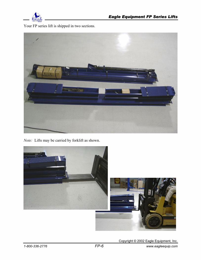
Your FP series lift is shipped in two sections.
Note: Lifts may be carried by forklift as shown.
Copyright © 2002 Eagle Equipment, Inc. 1-800-336-2776 FP-6 www.eagleequip.com
EEaaggllee EEqquuiippmmeenntt FFPP SSeerriieess LLiiffttss
1-800-336-27
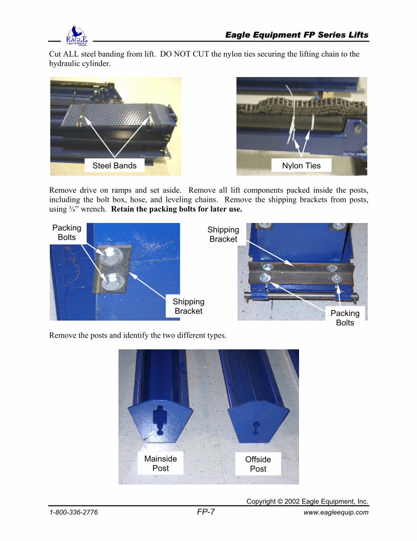
Cut ALL steel banding from lift. DO NOT CUT the nylon ties securing the lifting chain to the hydraulic cylinder.
Remove driincluding thusing ¾” wr
Remove the
s s
Packing Bolts
Steel Band
Copyright 76 FP-7
ve on ramps and set aside. Remove all lift componene bolt box, hose, and leveling chains. Remove the shiench. Retain the packing bolts for later use.
posts and identify the two different types.
Nylon Tie
ts packed inside the posts, pping brackets from posts,
Packing
Shipping BracketShipping Bracket
Bolts
Mainside Post
Offside Post
© 2002 Eagle Equipment, Inc. www.eagleequip.com
EEaaggllee EEqquuiippmmeenntt FFPP SSeerriieess LLiiffttss
Copyright © 2002 Eagle Equipment, Inc. 1-800-336-2776 FP-8 www.eagleequip.com
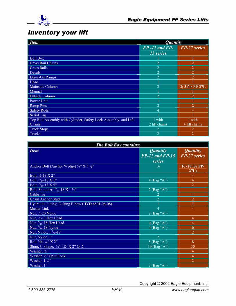
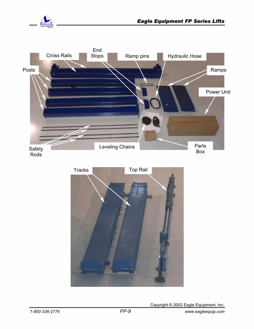
Inventory your lift Item Quantity
FP -12 and FP-15 series
FP-27 series
Bolt Box 1 1 Cross Rail Chains 2 2 Cross Rails 2 2 Decals 2 2 Drive-On Ramps 2 2 Hose 1 1 Mainside Column 2 2; 3 for FP-27L Manual 1 1 Offside Column 2 2 Power Unit 1 1 Ramp Pins 2 2 Safety Rods 4 4 Serial Tag 1 1 Top Rail Assembly with Cylinder, Safety Lock Assembly, and Lift Chains
1 with 2 lift chains
1 with 4 lift chains
Track Stops 2 2 Tracks 2 2
The Bolt Box contains:
Item Quantity FP-12 and FP-15
series
Quantity FP-27 series
Anchor Bolt (Anchor Wedge) ¾” X 5 ½” 16 16 (20 for FP-27L)
Bolt, ½-13 X 2” 4 Bolt, 5/16-18 X 1” 4 (Bag “A”) 4 Bolt, 5/16-18 X 5” 2 Bolt, Shoulder, 5/16-18 X 1 ½” 2 (Bag “A”) Cable Tie 2 4 Chain Anchor Stud 2 2 Hydraulic Fitting, O-Ring Elbow (HYD 6801-06-08) 1 1 Master Link 4 4 Nut, ¼-20 Nyloc 2 (Bag “A”) Nut, ½-13 Hex Head 4 Nut, 5/16-18 Hex Head 4 (Bag “A”) 4 Nut, 5/16-18 Nyloc 4 (Bag “A”) 6 Nut, Nyloc, 1 1/8-12” 2 Nut, Nyloc, 1” 2 Roll Pin, ¼” X 2” 8 (Bag “A”) 8 Shim, C Shape, ¾” I.D. X 2” O.D. 30 (Bag “A”) 30 Washer, ½” 4 Washer, ½” Split Lock 4 Washer, 1 ¼” 2 Washer, 1” 2 (Bag “A”)
EEaaggllee EEqquuiippmmeenntt FFPP SSeerriieess LLiiffttss
Copyright © 2002 Eagle Equipment, Inc. 1-800-336-2776 FP-9 www.eagleequip.com
Tracks Top Rail
Cross Rails
Posts Ramps
Safety Rods
Power Unit
Parts Box
End Stops Ramp pins
Leveling Chains
Hydraulic Hose
EEaaggllee EEqquuiippmmeenntt FFPP SSeerriieess LLiiffttss
Copyright © 201-800-336-2776 FP-10
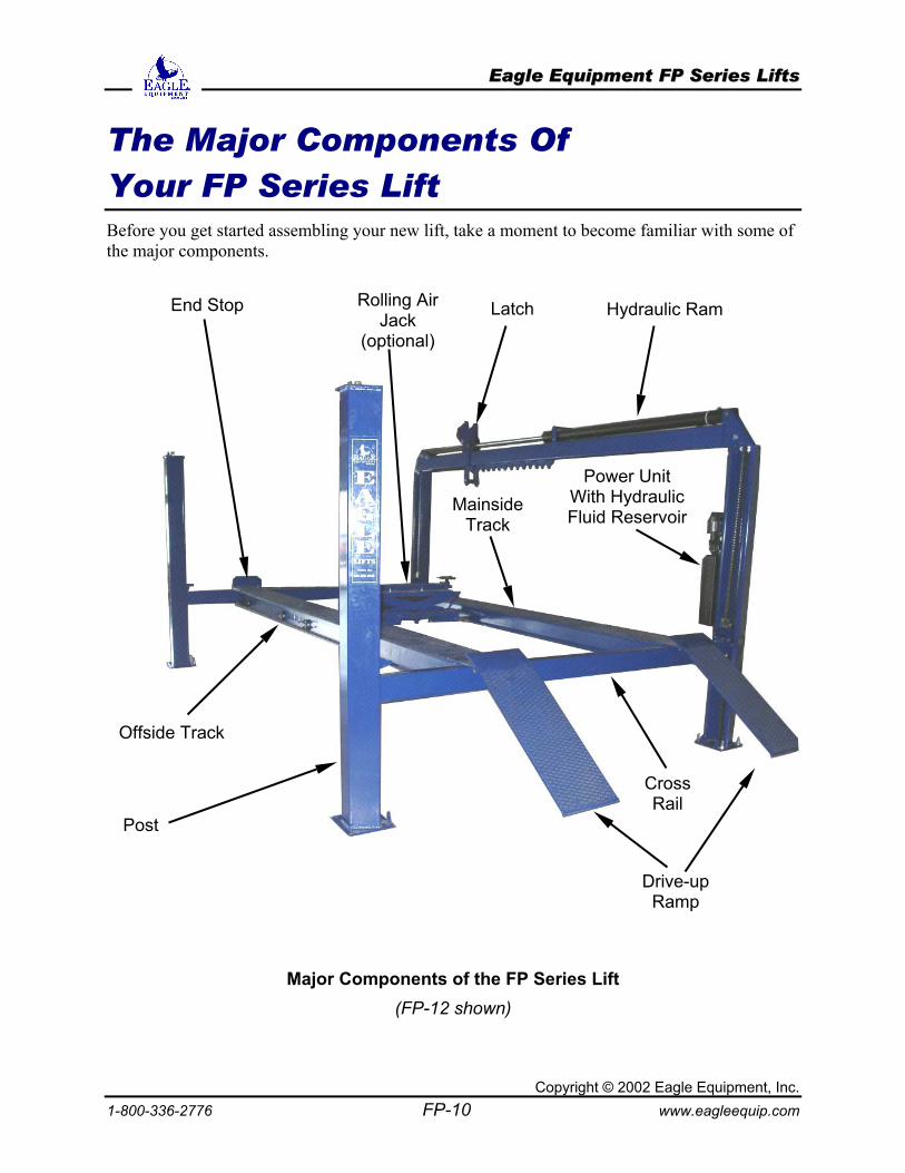
The Major Components Of Your FP Series Lift Before you get started assembling your new lift, take a moment to become familiar with some of the major components.
Major Components of the FP Series Lift (FP-12 shown)
Post
Rolling Air Jack
(optional)
Mainside Track
Offside Track
Power Unit With Hydraulic Fluid Reservoir
Hydraulic Ram End Stop Latch
Cross Rail
Drive-upRamp
02 Eagle Equipment, Inc. www.eagleequip.com
EEaaggllee EEqquuiippmmeenntt FFPP SSeerriieess LLiiffttss
Copyright © 2002 Eagle Equipment, Inc. 1-800-336-2776 FP-11 www.eagleequip.com
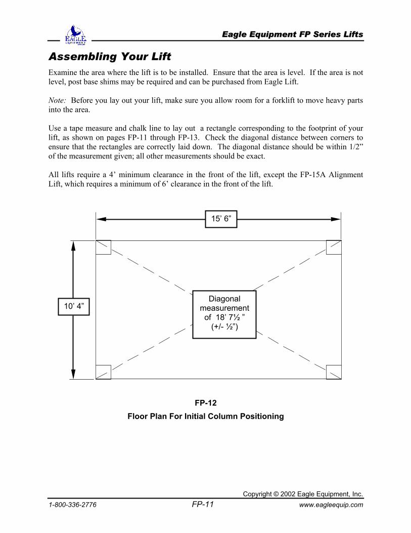
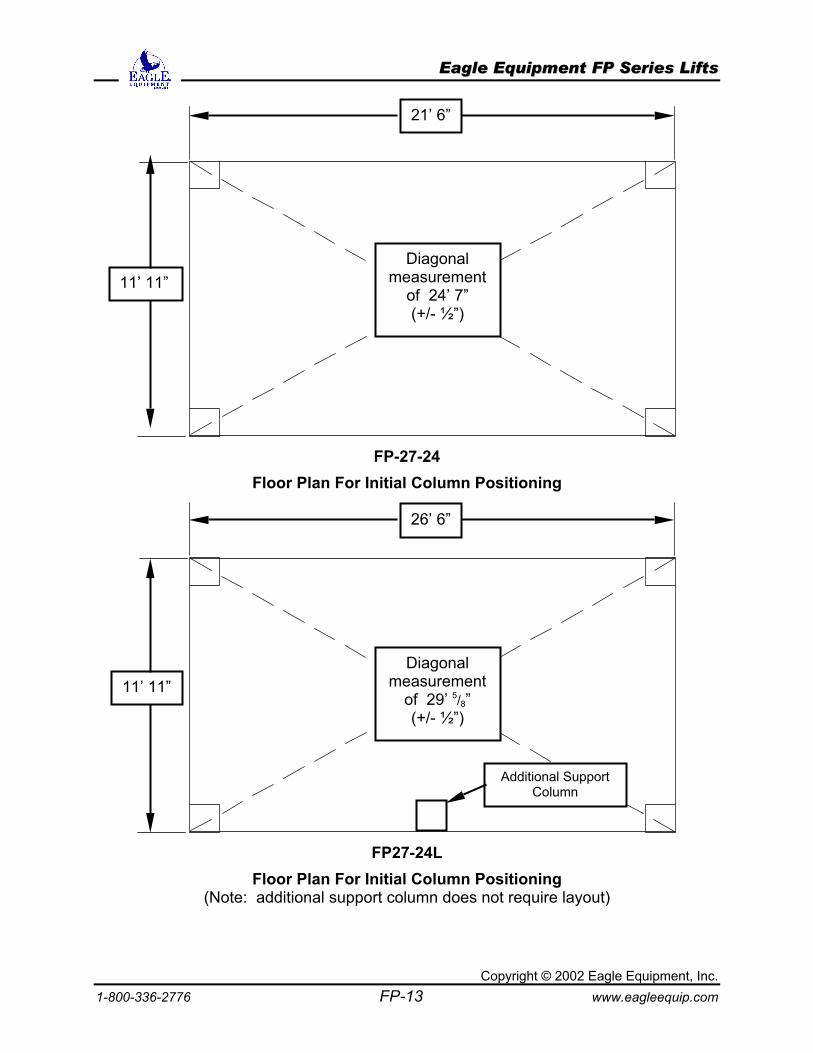
Assembling Your Lift Examine the area where the lift is to be installed. Ensure that the area is level. If the area is not level, post base shims may be required and can be purchased from Eagle Lift. Note: Before you lay out your lift, make sure you allow room for a forklift to move heavy parts into the area. Use a tape measure and chalk line to lay out a rectangle corresponding to the footprint of your lift, as shown on pages FP-11 through FP-13. Check the diagonal distance between corners to ensure that the rectangles are correctly laid down. The diagonal distance should be within 1/2” of the measurement given; all other measurements should be exact. All lifts require a 4’ minimum clearance in the front of the lift, except the FP-15A Alignment Lift, which requires a minimum of 6’ clearance in the front of the lift.
FP-12 Floor Plan For Initial Column Positioning
15’ 6”
10’ 4” Diagonal
measurement of 18’ 7½ ”
(+/- ½”)
EEaaggllee EEqquuiippmmeenntt FFPP SSeerriieess LLiiffttss
Copyright © 2002 Eagle Equipment, Inc. 1-800-336-2776 FP-12 www.eagleequip.com
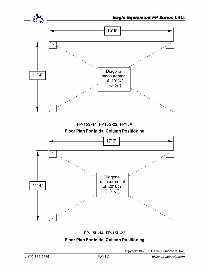
FP-15S-14, FP15S-22, FP15A Floor Plan For Initial Column Positioning
FP-15L-14, FP-15L-22 Floor Plan For Initial Column Positioning
15’ 6”
11’ 4” Diagonal
measurement of 19’ ¼” (+/- ½”)
11’ 4”
17’ 2”
Diagonal measurement
of 20’ 6¾” (+/- ½”)
EEaaggllee EEqquuiippmmeenntt FFPP SSeerriieess LLiiffttss
Copyright © 2002 Eagle Equipment, Inc. 1-800-336-2776 FP-13 www.eagleequip.com
FP-27-24
Floor Plan For Initial Column Positioning
FP27-24L
Floor Plan For Initial Column Positioning (Note: additional support column does not require layout)
21’ 6”
11’ 11” Diagonal
measurement of 24’ 7” (+/- ½”)
26’ 6”
11’ 11” Diagonal
measurement of 29’ 5/8” (+/- ½”)
Additional Support Column
EEaaggllee EEqquuiippmmeenntt FFPP SSeerriieess LLiiffttss
Copyright © 2002 Eagle Equipment, Inc. 1-800-336-2776 FP-14 www.eagleequip.com
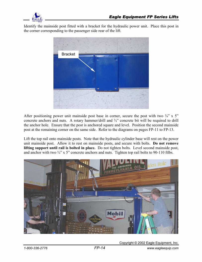
Identify the mainside post fitted with a bracket for the hydraulic power unit. Place this post in the corner corresponding to the passenger side rear of the lift.
After positioning power unit mainside post base in corner, secure the post with two ¾” x 5” concrete anchors and nuts. A rotary hammer/drill and ¾” concrete bit will be required to drill the anchor hole. Ensure that the post is anchored square and level. Position the second mainside post at the remaining corner on the same side. Refer to the diagrams on pages FP-11 to FP-13. Lift the top rail onto mainside posts. Note that the hydraulic cylinder base will rest on the power unit mainside post. Allow it to rest on mainside posts, and secure with bolts. Do not remove lifting support until rail is bolted in place. Do not tighten bolts. Level second mainside post, and anchor with two ¾” x 5” concrete anchors and nuts. Tighten top rail bolts to 90-110 ftlbs.
Bracket
EEaaggllee EEqquuiippmmeenntt FFPP SSeerriieess LLiiffttss
Copyright © 2002 Eagle Equipment, Inc. 1-800-336-2776 FP-15 www.eagleequip.com
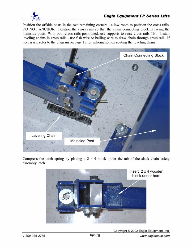
Position the offside posts in the two remaining corners - allow room to position the cross rails. DO NOT ANCHOR. Position the cross rails so that the chain connecting block is facing the mainside posts. With both cross rails positioned, use supports to raise cross rails 16”. Install leveling chains in cross rails - use fish wire or bailing wire to draw chain through cross rail. If necessary, refer to the diagram on page 18 for information on routing the leveling chain.
Compress the latch spring by placing a 2 x 4 block under the tab of the slack chain safety assembly latch.
Chain Connecting Block
Mainside Post Leveling Chain
Insert 2 x 4 wooden block under here
EEaaggllee EEqquuiippmmeenntt FFPP SSeerriieess LLiiffttss
Copyright © 2002 Eagle Equipment, Inc. 1-800-336-2776 FP-16 www.eagleequip.com
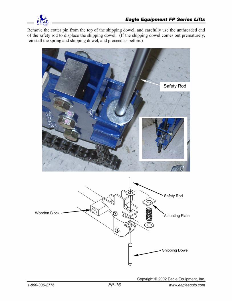
Remove the cotter pin from the top of the shipping dowel, and carefully use the unthreaded end of the safety rod to displace the shipping dowel. (If the shipping dowel comes out prematurely, reinstall the spring and shipping dowel, and proceed as before.)
Safety Rod
Safety Rod
Wooden Block
Shipping Dowel
Actuating Plate
EEaaggllee EEqquuiippmmeenntt FFPP SSeerriieess LLiiffttss
Copyright © 2002 Eagle Equipment, Inc. 1-800-336-2776 FP-17 www.eagleequip.com
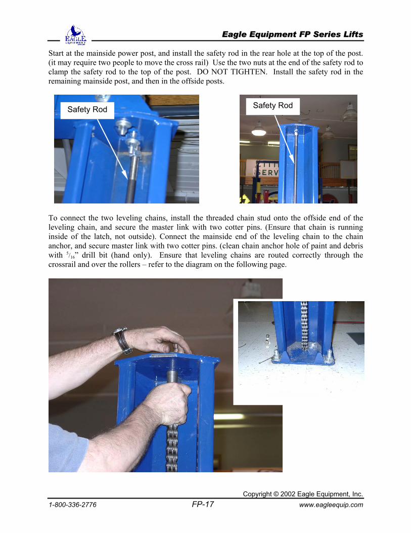
Start at the mainside power post, and install the safety rod in the rear hole at the top of the post. (it may require two people to move the cross rail) Use the two nuts at the end of the safety rod to clamp the safety rod to the top of the post. DO NOT TIGHTEN. Install the safety rod in the remaining mainside post, and then in the offside posts.
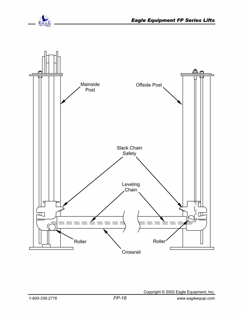
To connect the two leveling chains, install the threaded chain stud onto the offside end of the leveling chain, and secure the master link with two cotter pins. (Ensure that chain is running inside of the latch, not outside). Connect the mainside end of the leveling chain to the chain anchor, and secure master link with two cotter pins. (clean chain anchor hole of paint and debris with 5/16” drill bit (hand only). Ensure that leveling chains are routed correctly through the crossrail and over the rollers – refer to the diagram on the following page.
Safety Rod Safety Rod
EEaaggllee EEqquuiippmmeenntt FFPP SSeerriieess LLiiffttss
Copyright © 2002 Eagle Equipment, Inc. 1-800-336-2776 FP-18 www.eagleequip.com
Mainside Post
Offside Post
Leveling Chain
Roller Roller
Crossrail
Slack Chain Safety
EEaaggllee EEqquuiippmmeenntt FFPP SSeerriieess LLiiffttss
Copyright © 2002 Eagle Equipment, Inc. 1-800-336-2776 FP-19 www.eagleequip.com
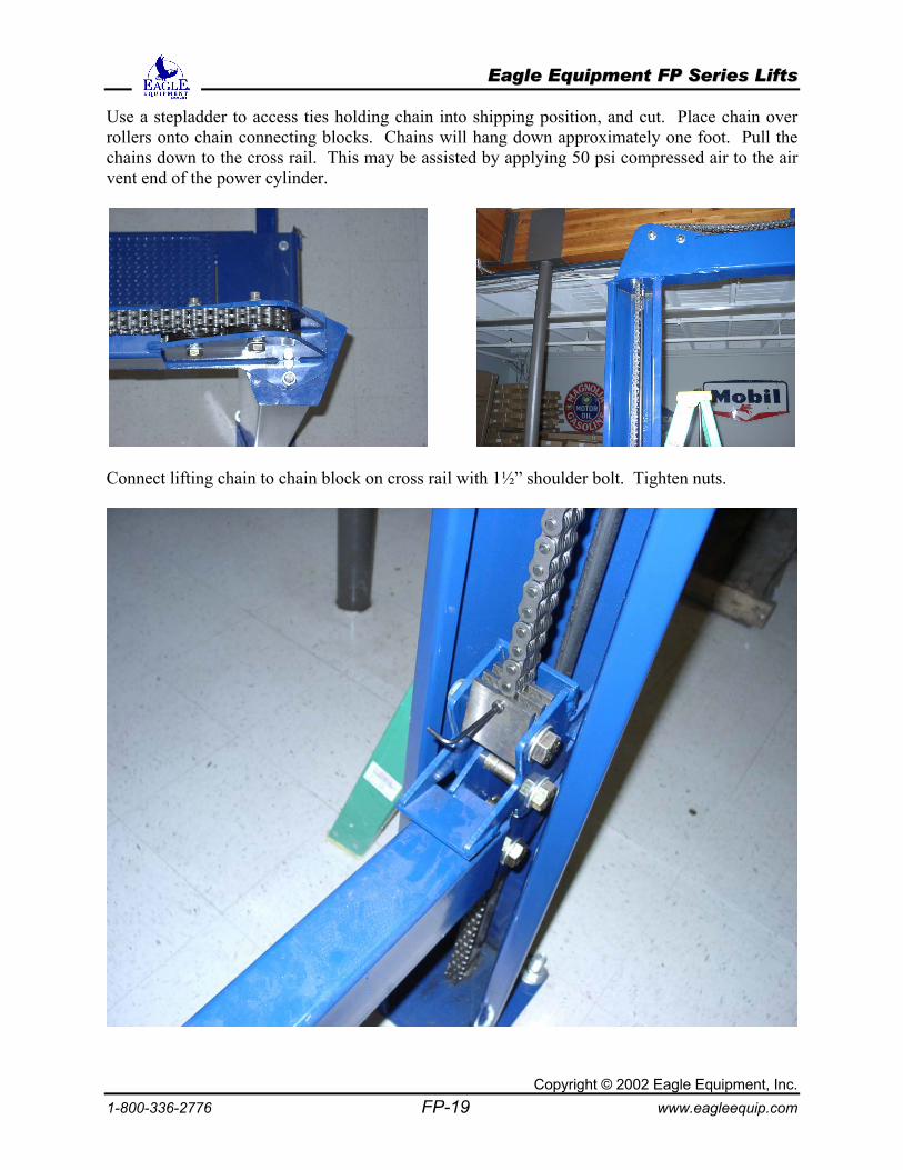
Use a stepladder to access ties holding chain into shipping position, and cut. Place chain over rollers onto chain connecting blocks. Chains will hang down approximately one foot. Pull the chains down to the cross rail. This may be assisted by applying 50 psi compressed air to the air vent end of the power cylinder.
Connect lifting chain to chain block on cross rail with 1½” shoulder bolt. Tighten nuts.
EEaaggllee EEqquuiippmmeenntt FFPP SSeerriieess LLiiffttss
Copyright © 2002 Eagle Equipment, Inc. 1-800-336-2776 FP-20 www.eagleequip.com
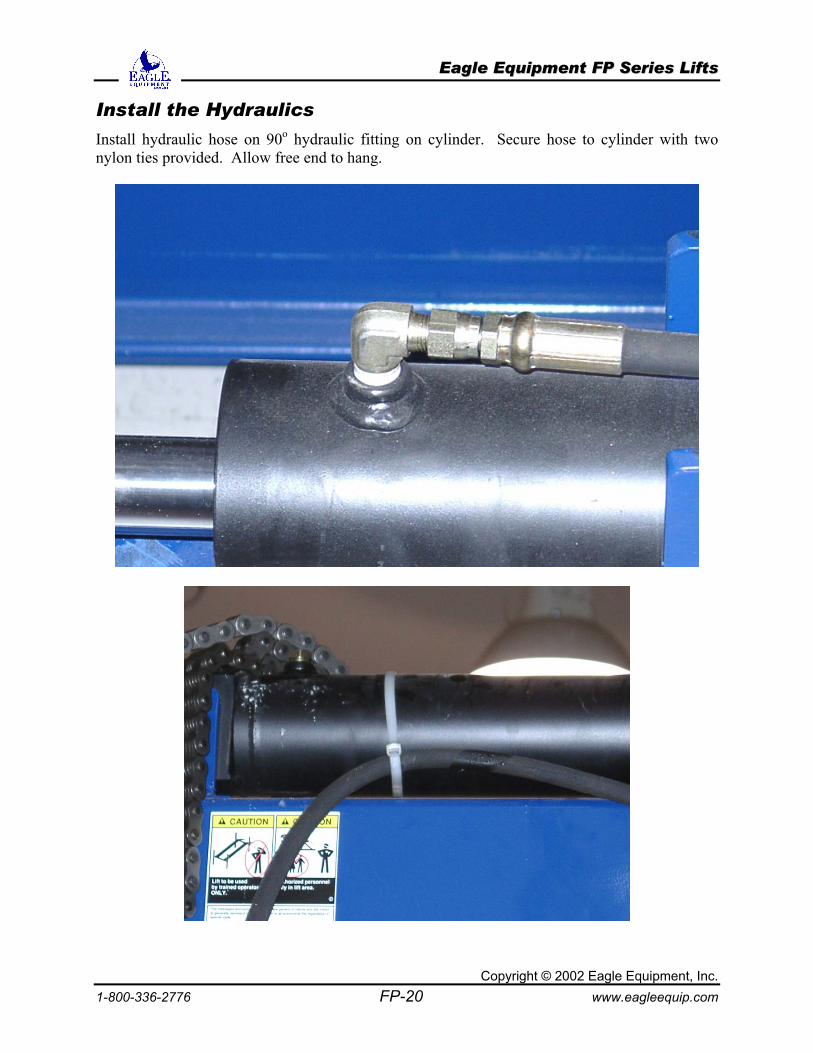
Install the Hydraulics
Install hydraulic hose on 90o hydraulic fitting on cylinder. Secure hose to cylinder with two nylon ties provided. Allow free end to hang.
EEaaggllee EEqquuiippmmeenntt FFPP SSeerriieess LLiiffttss
Copyright © 2002 Eagle Equipment, Inc. 1-800-336-2776 FP-21 www.eagleequip.com
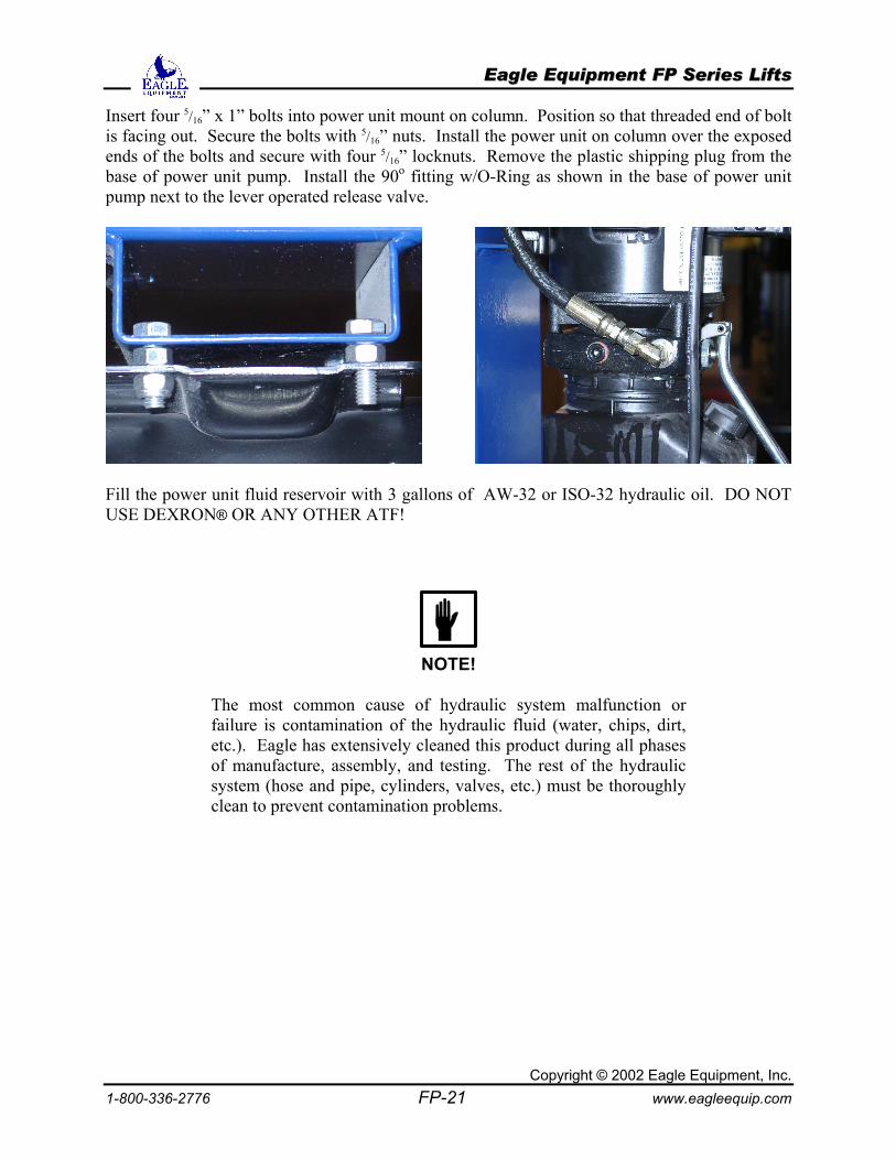
Insert four 5/16” x 1” bolts into power unit mount on column. Position so that threaded end of bolt is facing out. Secure the bolts with 5/16” nuts. Install the power unit on column over the exposed ends of the bolts and secure with four 5/16” locknuts. Remove the plastic shipping plug from the base of power unit pump. Install the 90o fitting w/O-Ring as shown in the base of power unit pump next to the lever operated release valve.
Fill the power unit fluid reservoir with 3 gallons of AW-32 or ISO-32 hydraulic oil. DO NOT USE DEXRON® OR ANY OTHER ATF!
NOTE!
The most common cause of hydraulic system malfunction or failure is contamination of the hydraulic fluid (water, chips, dirt, etc.). Eagle has extensively cleaned this product during all phases of manufacture, assembly, and testing. The rest of the hydraulic system (hose and pipe, cylinders, valves, etc.) must be thoroughly clean to prevent contamination problems.
EEaaggllee EEqquuiippmmeenntt FFPP SSeerriieess LLiiffttss
Copyright © 2002 Eagle Equipment, Inc. 1-800-336-2776 FP-22 www.eagleequip.com
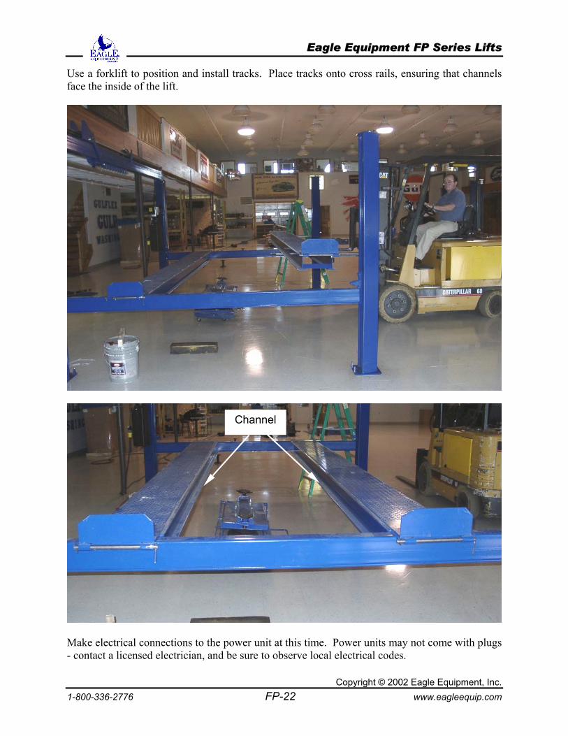
Use a forklift to position and install tracks. Place tracks onto cross rails, ensuring that channels face the inside of the lift.
Make electrical connections to the power unit at this time. Power units may not come with plugs - contact a licensed electrician, and be sure to observe local electrical codes.
Channel
EEaaggllee EEqquuiippmmeenntt FFPP SSeerriieess LLiiffttss
Copyright © 2002 Eagle Equipment, Inc. 1-800-336-2776 FP-23 www.eagleequip.com
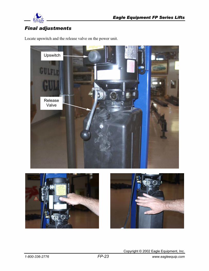
Final adjustments Locate upswitch and the release valve on the power unit.
Upswitch
Release Valve
EEaaggllee EEqquuiippmmeenntt FFPP SSeerriieess LLiiffttss
Copyright © 2002 Eagle Equipment, Inc. 1-800-336-2776 FP-24 www.eagleequip.com
Bleed the Hydraulic System
Press the upswitch and run for approximately 15 seconds, or until the ram just begins to move. Depress release valve. Air should be audibly escaping into reservoir (bubbling sound). Repeat this process twice more to finish bleeding air from system. Level the Lift
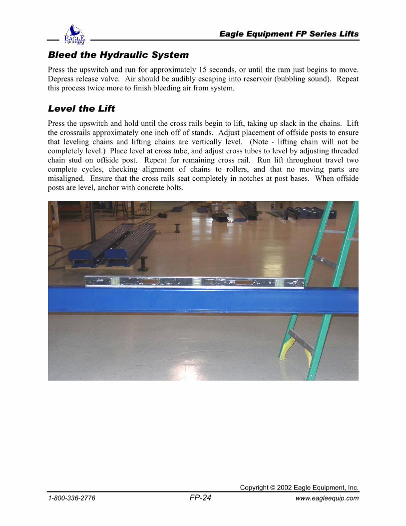
Press the upswitch and hold until the cross rails begin to lift, taking up slack in the chains. Lift the crossrails approximately one inch off of stands. Adjust placement of offside posts to ensure that leveling chains and lifting chains are vertically level. (Note - lifting chain will not be completely level.) Place level at cross tube, and adjust cross tubes to level by adjusting threaded chain stud on offside post. Repeat for remaining cross rail. Run lift throughout travel two complete cycles, checking alignment of chains to rollers, and that no moving parts are misaligned. Ensure that the cross rails seat completely in notches at post bases. When offside posts are level, anchor with concrete bolts.
EEaaggllee EEqquuiippmmeenntt FFPP SSeerriieess LLiiffttss
Copyright © 2002 Eagle Equipment, Inc. 1-800-336-2776 FP-25 www.eagleequip.com
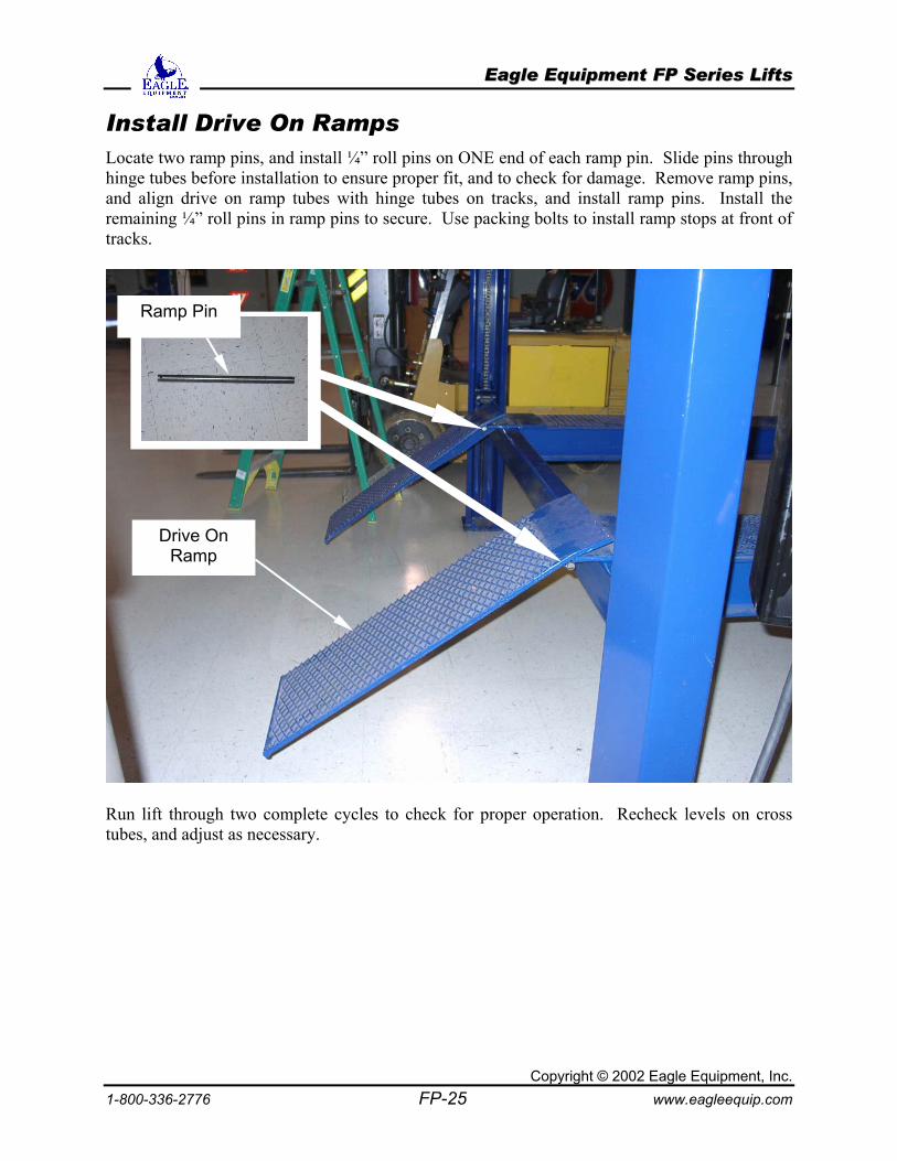
Install Drive On Ramps Locate two ramp pins, and install ¼” roll pins on ONE end of each ramp pin. Slide pins through hinge tubes before installation to ensure proper fit, and to check for damage. Remove ramp pins, and align drive on ramp tubes with hinge tubes on tracks, and install ramp pins. Install the remaining ¼” roll pins in ramp pins to secure. Use packing bolts to install ramp stops at front of tracks.
Run lift through two complete cycles to check for proper operation. Recheck levels on cross tubes, and adjust as necessary.
Ramp Pin
Drive On Ramp
EEaaggllee EEqquuiippmmeenntt FFPP SSeerriieess LLiiffttss
Copyright © 2002 Eagle Equipment, Inc. 1-800-336-2776 FP-26 www.eagleequip.com
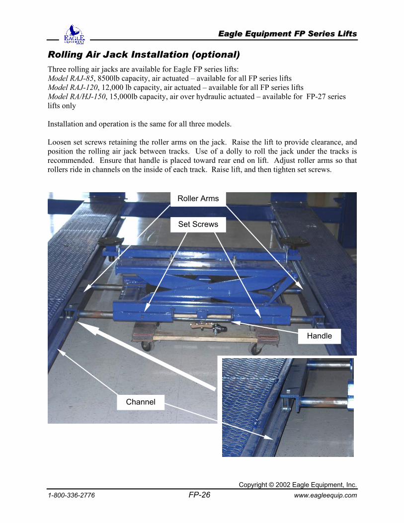
Rolling Air Jack Installation (optional)
Three rolling air jacks are available for Eagle FP series lifts: Model RAJ-85, 8500lb capacity, air actuated – available for all FP series lifts Model RAJ-120, 12,000 lb capacity, air actuated – available for all FP series lifts Model RA/HJ-150, 15,000lb capacity, air over hydraulic actuated – available for FP-27 series lifts only Installation and operation is the same for all three models. Loosen set screws retaining the roller arms on the jack. Raise the lift to provide clearance, and position the rolling air jack between tracks. Use of a dolly to roll the jack under the tracks is recommended. Ensure that handle is placed toward rear end on lift. Adjust roller arms so that rollers ride in channels on the inside of each track. Raise lift, and then tighten set screws.
Set Screws
Roller Arms
Handle
Channel
EEaaggllee EEqquuiippmmeenntt FFPP SSeerriieess LLiiffttss
Copyright © 2002 Eagle Equipment, Inc. 1-800-336-2776 FP-27 www.eagleequip.com
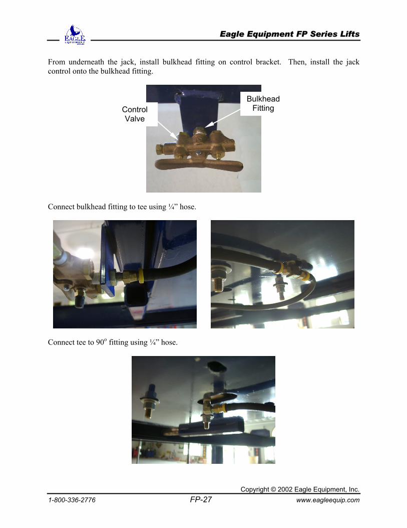
From underneath the jack, install bulkhead fitting on control bracket. Then, install the jack control onto the bulkhead fitting.
Connect bulkhead fitting to tee using ¼” hose.
Connect tee to 90o fitting using ¼” hose.
Bulkhead Fitting Control
Valve
EEaaggllee EEqquuiippmmeenntt FFPP SSeerriieess LLiiffttss
Copyright © 2002 Eagle Equipment, Inc. 1-800-336-2776 FP-28 www.eagleequip.com
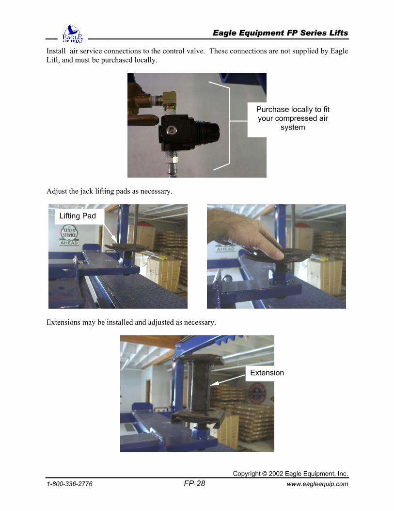
Install air service connections to the control valve. These connections are not supplied by Eagle Lift, and must be purchased locally.
Adjust the jack lifting pads as necessary.
Extensions may be installed and adjusted as necessary.
Purchase locally to fit your compressed air
system
Lifting Pad
Extension
EEaaggllee EEqquuiippmmeenntt FFPP SSeerriieess LLiiffttss
Copyright © 2002 Eagle Equipment, Inc. 1-800-336-2776 FP-29 www.eagleequip.com
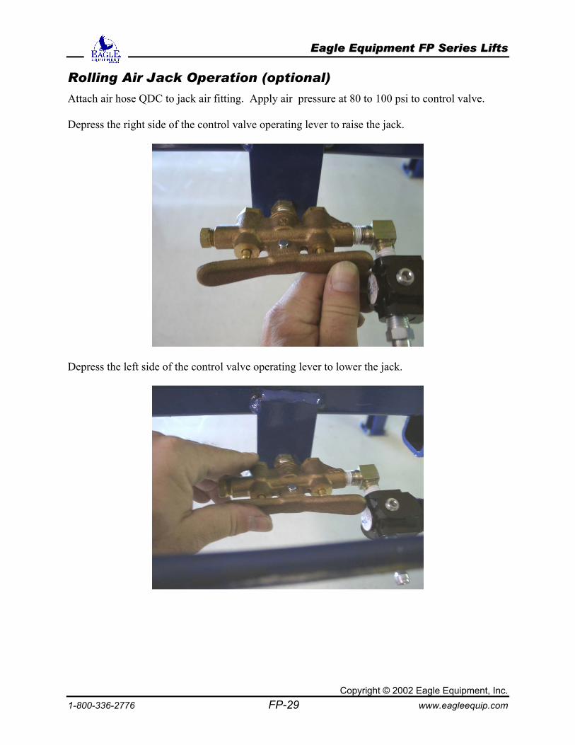
Rolling Air Jack Operation (optional)
Attach air hose QDC to jack air fitting. Apply air pressure at 80 to 100 psi to control valve. Depress the right side of the control valve operating lever to raise the jack.
Depress the left side of the control valve operating lever to lower the jack.
EEaaggllee EEqquuiippmmeenntt FFPP SSeerriieess LLiiffttss
Copyright © 2002 Eagle Equipment, Inc. 1-800-336-2776 FP-30 www.eagleequip.com
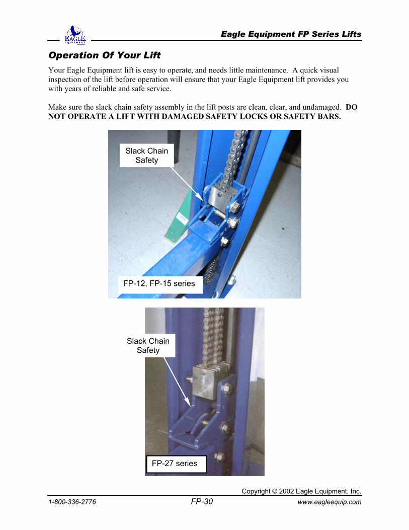
Operation Of Your Lift
Your Eagle Equipment lift is easy to operate, and needs little maintenance. A quick visual inspection of the lift before operation will ensure that your Eagle Equipment lift provides you with years of reliable and safe service. Make sure the slack chain safety assembly in the lift posts are clean, clear, and undamaged. DO NOT OPERATE A LIFT WITH DAMAGED SAFETY LOCKS OR SAFETY BARS.
FP-12, FP-15 series
FP-27 series
Slack Chain Safety
Slack Chain Safety
EEaaggllee EEqquuiippmmeenntt FFPP SSeerriieess LLiiffttss
1-800-336-2776
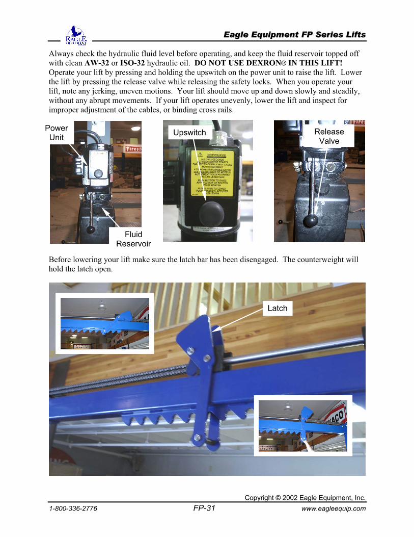
Always check the hydraulic fluid level before operating, and keep the fluid reservoir topped off with clean AW-32 or ISO-32 hydraulic oil. DO NOT USE DEXRON® IN THIS LIFT! Operate your lift by pressing and holding the upswitch on the power unit to raise the lift. Lower the lift by pressing the release valve while releasing the safety locks. When you operate your lift, note any jerking, uneven motions. Your lift should move up and down slowly and steadily, without any abrupt movements. If your lift operates unevenly, lower the lift and inspect for improper adjustment of the cables, or binding cross rails.
Before lowering your lift make suhold the latch open.
R
CopyrighFP-31
re the latch bar has been disengage
L
Upswitcht © 2002 Eagww
d. The coun
atch
ReleaseValve
Power Unit
Fluid eservoir
terweight will
le Equipment, Inc. w.eagleequip.com
EEaaggllee EEqquuiippmmeenntt FFPP SSeerriieess LLiiffttss
Copyrigh1-800-336-2776 FP-32
Maintenance
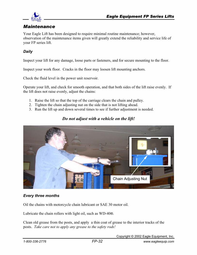
Your Eagle Lift has been designed to require minimal routine maintenance; however, observation of the maintenance items given will greatly extend the reliability and service life of your FP series lift. Daily Inspect your lift for any damage, loose parts or fasteners, and for secure mounting to the floor. Inspect your work floor. Cracks in the floor may loosen lift mounting anchors. Check the fluid level in the power unit reservoir. Operate your lift, and check for smooth operation, and that both sides of the lift raise evenly. If the lift does not raise evenly, adjust the chains:
1. Raise the lift so that the top of the carriage clears the chain and pulley. 2. Tighten the chain adjusting nut on the side that is not lifting ahead. 3. Run the lift up and down several times to see if further adjustment is needed.
Do not adjust with a vehicle on the lift!
Every three months Oil the chains with motorcycle chain lubricant or SAE 30 motor oil. Lubricate the chain rollers with light oil, such as WD-40®. Clean old grease from the posts, and apply a thin coat of grease to thposts. Take care not to apply any grease to the safety rods!
Chain Adj
t © 2002 Eagle Equipment, Inc. www.eagleequip.com
e interior tracks of the
usting Nut
EEaaggllee EEqquuiippmmeenntt FFPP SSeerriieess LLiiffttss
Copyright © 2002 Eagle Equipment, Inc. 1-800-336-2776 FP-33 www.eagleequip.com
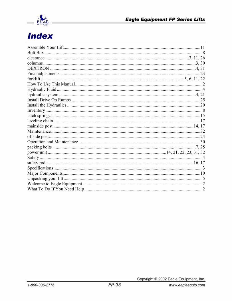
Index Assemble Your Lift........................................................................................................................11 Bolt Box...........................................................................................................................................8 clearance ..............................................................................................................................3, 11, 26 columns ......................................................................................................................................3, 30 DEXTRON ................................................................................................................................4, 31 Final adjustments ...........................................................................................................................23 forklift ..............................................................................................................................5, 6, 11, 22 How To Use This Manual................................................................................................................2 Hydraulic Fluid ................................................................................................................................4 hydraulic system ........................................................................................................................4, 21 Install Drive On Ramps .................................................................................................................25 Install the Hydraulics .....................................................................................................................20 Inventory ..........................................................................................................................................8 latch spring.....................................................................................................................................15 leveling chain .................................................................................................................................17 mainside post ...........................................................................................................................14, 17 Maintenance...................................................................................................................................32 offside post.....................................................................................................................................24 Operation and Maintenance ...........................................................................................................30 packing bolts ..............................................................................................................................7, 25 power unit ........................................................................................................14, 21, 22, 23, 31, 32 Safety ...............................................................................................................................................4 safety rod..................................................................................................................................16, 17 Specifications...................................................................................................................................3 Major Components.........................................................................................................................10 Unpacking your lift ..........................................................................................................................5 Welcome to Eagle Equipment .........................................................................................................2 What To Do If You Need Help........................................................................................................2

EEaaggllee EEqquuiippmmeenntt FFPP SSeerriieess LLiiffttss
Copyright © 2002 Eagle Equipment, Inc. 1-800-336-2776 FP-34 www.eagleequip.com
Notes
EEaaggllee EEqquuiippmmeenntt FFPP SSeerriieess LLiiffttss
Copyright © 2002 Eagle Equipment, Inc. 1-800-336-2776 FP-35 www.eagleequip.com
Eagle Equipment, Inc. provides this publication “as is” without warranty of any kind, either expressed or implied, including but not limited to the implied warranties of merchantability or fitness for a particular purpose. Some states or jurisdictions do not allow disclaimer of express or implied warranties in certain transactions; therefore, this statement may not apply to you. Eagle Equipment reserves the right to revise this publication and to make changes from time to time in the content hereof without obligation of Eagle Equipment to notify any person of such revision or changes. Copyright © 2002 by Eagle Equipment, Inc. All rights reserved. No part of this publication may be transmitted, transcribed, reproduced, stored in any retrieval system or translated into any language or computer language in any form or by any means, mechanical, electronic, magnetic, optical, chemical, manual, or otherwise, without the prior written consent of Eagle Equipment, Inc., P.O. Box 420, Chartley MA 02712-0420. Printed in the United States of America. Trademarks And Credits Dexron™ is a registered trademark of General Motors Corporation. WD-40™ is a registered trademark of WD-40 Company. Other terms used in this manual are the trademarks of their respective holders.