Embed Size (px)
Citation preview
PAGE 1 OF 28EDITION 1 Z Z JANUARY 1995
EAL-G17 Z CMM CALIBRATION
Coordinate Measuring Machine
Calibration
EAL European cooperation forAccreditation of Laboratories
Publication ReferenceWELAC Guidance Document WGD 8 EAL-G17
PURPOSE
This document has been produced by EAL to provide information on the measurementcapabilities of coordinate measuring machines (CMMs) and the treatment of measureddata, and to provide guidance to national accreditation bodies accrediting laboratoriesto perform task-related calibrations of CMMs, or to use CMMs for the calibration ofcomponents.
EAL-G17 Z CMM CALIBRATION
EDITION 1 Z Z JANUARY 1995PAGE 2 OF 28
Authorship
This publication has been written by the EAL Expert Group Dimensional Metrology working groupon CMMs.
Official language
The text may be translated into other languages as required. The English language version remainsthe definitive version.
Copyright
The copyright of this text is held by EAL. The text may not be copied for resale.
Further informationFor further information about this publication, contact your National member of EAL, whose telephoneand facsimile numbers are given below:
Calib National member Testing Nationalmember
Austria BMwA BMwATel: +431 711 02 233 Tel: +431 711 02 249Fax: +431 714 35 82 Fax: +431 714 35 82
Belgium BKO/OBE BELTESTTel: +322 233 6111 Tel: +32 2 548 15 11Fax: +322 230 8300 Fax: +32 2 514 47 56
Denmark DANAK DANAKTel: +45 35 86 86 86 Tel: +45 35 86 86 86Fax: +45 35 86 86 87 Fax: +45 35 86 86 87
Finland FINAS FINASTel: +358 0 61671 Tel: +358 0 61671Fax: +358 0 6167 467 Fax: +358 0 6167 467
France COFRAC COFRACTel: +33 1 44 68 82 20 Tel: +33 1 44 68 82 20Fax: +33 1 44 68 82 21 Fax: +33 1 44 68 82 21
Germany DKD DARTel: +49 531 592 8320 Tel: +49 30 8104 1710Fax: +49 531 592 9292 Fax: +49 30 8104 1717
Greece Ministry of Commerce ELOTTel: +30 1 36 14 168 Tel: +30 1 201 5025Fax: +30 1 36 42 642 Fax: +30 1 202 0776
Iceland ISAC ISACTel: +354 1 681 122 Tel: +354 1 681 122Fax: +354 1 685 998 Fax: +354 1 685 998
Ireland ICLAB ICLABTel: +353 1 370 101 Tel: +353 1 370 101
Calib National member Testing Nationalmember
Fax: +353 1 368 738 Fax: +353 1 368 738
Italy SIT SINALTel: +39 11 348 8933 Tel: +39 6 487 1176Fax: +39 11 34 6384 Fax: +39 6 481 4563
Netherlands NKO/STERIN/STERLAB NKO/STERIN/STERLABTel: +31 10 413 6011 Tel: +31 10 413 6011Fax: +31 10 413 3557 Fax: +31 10 413 3557
Norway NA NATel: +47 22 20 0226 Tel: +47 22 20 0226Fax: +47 22 20 7772 Fax: +47 22 20 7772
Portugal IPQ IPQTel: +351 1 52 3978 Tel: +351 1 52 3978Fax: +351 1 3153676 Fax: +351 1 3153676
Spain SCI RELETel: +34 1 349 4711 Tel: +34 1 564 96 87Fax: +34 1 457 8066 Fax: +34 1 563 04 54
Sweden SWEDAC SWEDACTel: +46 33 17 7700 Tel: +46 33 17 7700Fax: +46 33 10 1392 Fax: +46 33 10 1392
Switzerland SAS SASTel: +41 31 963 3111 Tel: +41 31 963 3412Fax: +41 31 963 3210 Fax: +41 31 963 3210
United Kingdom NAMAS NAMASTel: +44 181 943 7068 Tel: +44 181 943 6266Fax: +44 181 943 7134 Fax: +44 181 943 7134
PAGE 3 OF 28EDITION 1 Z Z JANUARY 1995
EAL-G17 Z CMM CALIBRATION
Section Page
Contents
1 Summary 4
2 Introduction 4
3 Calibration and performance verification of CMMs 5
4 Accreditation of calibration laboratories 6
5 Calibration procedures 7
6 Calibration certificates 10
7 Future 11
8 References 11
Appendix A Terms and definitions 13
Appendix B Accreditation of laboratories for the calibration of CMMs 16
Appendix C Accreditation of laboratories for calibration of artefactsusing CMMs 17
Appendix D Comparator approach 18
Appendix E Error synthesis approach 20
Appendix F Recommendations for future developments 27
EAL-G17 Z CMM CALIBRATION
EDITION 1 Z Z JANUARY 1995PAGE 4 OF 28
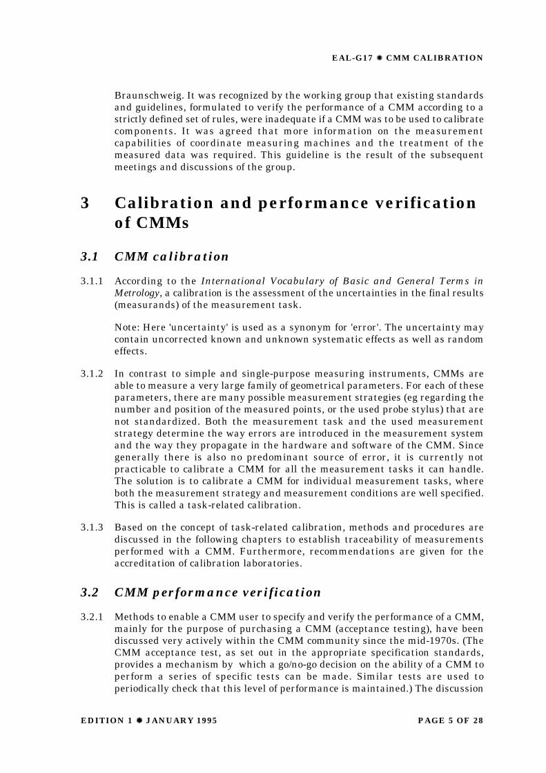
1 Summary
1.1 The aim of this guideline is to demonstrate the ways in which traceability formeasurements using a coordinate measuring machine (CMM) can be achieved.
1.2 Coordinate metrology has become essential for industrial dimensional metrology.In recent years, standards and guidelines have been developed to harmonizethe performance specification of a CMM for a user when purchasing a machineand, once purchased, to provide a well-defined way in which the specifiedperformance can be verified.
1.3 A further step in the harmonization process is to establish ways of calibratingcomponents with a CMM, i.e. measuring a component, assessing theuncertainties of the respective measurands, and issuing a certificate, theauthenticity of which would be recognised throughout the Western EuropeanCalibration Cooperation (WECC). However, due to the complex errors andversatility of a CMM, it is difficult to specify and verify the uncertainty of allmeasurement tasks that can be executed by a CMM, in any position within itsworking volume, using any measurement strategy.
1.4 The solution suggested in this guideline is for a laboratory to demonstrate itsability to assess the uncertainty of those measurement tasks for whichaccreditation is desired. This leads to the concept of task-related calibration,where only those error sources are analysed that affect the particularmeasurement task and associated measurement procedure specified in thecertificate. For some tasks, this will be relatively easy to achieve.
1.5 This guideline describes two basic principles of CMM task-related calibration:the comparator principle and the error synthesis principle. It further summarisesthe views of experts about the related calibration techniques.
1.6 The functions of this document are to:
W emphasise the difference between CMM performance verification and CMMcalibration,
W define CMM task-related calibration and to describe the problems involved,
W provide guidance to the various national accreditation bodies accreditinglaboratories to perform task-related calibrations of CMMs and/or to useCMMs for the calibration of components.
2 Introduction
2.1 In response to requests from firms and organisations, various nationalcalibration organisations are studying the calibration of Coordinate MeasuringMachines (CMMs) and the use of CMMs to calibrate components. Someorganisations have issued accreditations for the calibration of componentsalready. In order to harmonize these efforts, a WECC working group wasestablished, which held its first meeting on 4 April 1990 at the PTB,
PAGE 5 OF 28EDITION 1 Z Z JANUARY 1995
EAL-G17 Z CMM CALIBRATION
Braunschweig. It was recognized by the working group that existing standardsand guidelines, formulated to verify the performance of a CMM according to astrictly defined set of rules, were inadequate if a CMM was to be used to calibratecomponents. It was agreed that more information on the measurementcapabilities of coordinate measuring machines and the treatment of themeasured data was required. This guideline is the result of the subsequentmeetings and discussions of the group.
3 Calibration and performance verificationof CMMs
3.1 CMM calibration
3.1.1 According to the International Vocabulary of Basic and General Terms inMetrology, a calibration is the assessment of the uncertainties in the final results(measurands) of the measurement task.
Note: Here 'uncertainty' is used as a synonym for 'error'. The uncertainty maycontain uncorrected known and unknown systematic effects as well as randomeffects.
3.1.2 In contrast to simple and single-purpose measuring instruments, CMMs areable to measure a very large family of geometrical parameters. For each of theseparameters, there are many possible measurement strategies (eg regarding thenumber and position of the measured points, or the used probe stylus) that arenot standardized. Both the measurement task and the used measurementstrategy determine the way errors are introduced in the measurement systemand the way they propagate in the hardware and software of the CMM. Sincegenerally there is also no predominant source of error, it is currently notpracticable to calibrate a CMM for all the measurement tasks it can handle.The solution is to calibrate a CMM for individual measurement tasks, whereboth the measurement strategy and measurement conditions are well specified.This is called a task-related calibration.
3.1.3 Based on the concept of task-related calibration, methods and procedures arediscussed in the following chapters to establish traceability of measurementsperformed with a CMM. Furthermore, recommendations are given for theaccreditation of calibration laboratories.
3.2 CMM performance verification
3.2.1 Methods to enable a CMM user to specify and verify the performance of a CMM,mainly for the purpose of purchasing a CMM (acceptance testing), have beendiscussed very actively within the CMM community since the mid-1970s. (TheCMM acceptance test, as set out in the appropriate specification standards,provides a mechanism by which a go/no-go decision on the ability of a CMM toperform a series of specific tests can be made. Similar tests are used toperiodically check that this level of performance is maintained.) The discussion
EAL-G17 Z CMM CALIBRATION
EDITION 1 Z Z JANUARY 1995PAGE 6 OF 28
has resulted in the publication of several national and international standardsand guidelines describing the requirements for the performance verification,periodic reverification and interim checking of CMMs. Furthermore,supplementary documents have been prepared to help the CMM user with theinterpretation of the requirements of particular specification standards.
3.2.2 Most CMM performance verification standards and guidelines are based onsampling the length-measurement capability of a CMM, to decide whether itsperformance conforms to the specification. However from such a sample, it isnot possible to make an accurate statement about the overall length-measurement capability of a performance-verified CMM. This is due mainly tothe complicated ways in which errors combine within a CMM, which do notpermit statements about the uncertainty of its measurements anywhere in itsworkspace to be directly derived from such a limited sample. Furthermore, thereare no methods specified by which the uncertainty of other measurands can becalculated using only the length-measurement capability of a CMM.
3.2.3 Thus the sampled length-measurement uncertainty alone cannot be consideredas representative of all possible measurement tasks performed by a CMM.Therefore, performance verification does not guarantee traceability ofmeasurements performed with a CMM for all measurement tasks.
3.2.4 However, it is recognized by the working group that in an industrial environmentthe currently practised performance verifications and regular interim checks ofCMMs are the state of the art to approximate traceability in case no calibrationcertificate of the measured components is required.
4 Accreditation of calibration laboratories
4.1 The calibration of a mechanical component with a CMM is a complexmeasurement problem which involves many factors. Each requirement for eachgeometrical feature, or relationship between features, of the component undertest represents a separate measurement task for the CMM. Each measurementtask and measurement strategy used to solve it involves a different combinationof sources of uncertainties associated with the coordinate measuring system,i.e. the CMM and the environment in which the CMM is sited. Thus a generalcalibration of CMMs for all the measurement tasks it can handle is not practical.Hence the concept of task-related calibration is introduced where:
W accreditation can be granted only for precisely specified measurement tasks,conditions, and measurement strategies, according to one of the methodsdescribed in Section 5,
W only the sources of uncertainty contributing to the final uncertaintyassociated with the measurement task need to be identified and estimated,and
PAGE 7 OF 28EDITION 1 Z Z JANUARY 1995
EAL-G17 Z CMM CALIBRATION
W the accreditation bodies are responsible for harmonizing the measurementtasks, including measurement strategies, and the calibration procedures withthe requirements of this guideline, especially to analyse systematically theprecise nature of the measurement tasks required for the accreditation.
4.2 There are basically two types of technical solutions to accredit the use of CMMsto calibrate components:
W the use according to the comparator principle, and
W the use according to the 'error synthesis' technique (sometimes referred toas the parametric technique).
4.3 Regarding the task-related calibration of CMMs according to the error-synthesistechnique, additional accreditations are possible for:
W the measurement of the parametric errors of a CMM, and
W the evaluation of the uncertainty of a measurement task from the parametricerror data of the CMM, according to a specified, task related, procedure.This evaluation may be implemented in software.
4.4 Appendixes B and C give general rules which shall help to setup accreditationcontracts for the calibration of CMMs and the use of CMMs to calibratecomponents.
5 Calibration procedures
5.1 Comparator approach (see Appendix D)
5.1.1 The measurement of traceable reference objects yields directly the errorsassociated with specific measurement tasks. Thus the errors associated withthe parameters of the measured object due to the accuracy of the CMM (includingits software) can be determined directly. In view of the complex error structureof CMMs, calibrations of this kind are only valid for objects with essentially thesame geometrical form and size as the reference object used, measured in thesame location and using the same measurement strategy. Provided that suitablereference artefacts are available, this type of calibration procedure can achievehigh accuracy with relatively little effort.
5.1.2 Performing a comparator-type calibration is relatively straightforward. Thereference object is measured several times by the CMM. Here it is good practiceto make small changes in the location of the object and the measurementstrategy to establish the sensitivity of the measurements to small differencesbetween the final application of the measurement and such a calibration. Ingeneral, no analysis of errors associated with the CMM is required.
EAL-G17 Z CMM CALIBRATION
EDITION 1 Z Z JANUARY 1995PAGE 8 OF 28
5.1.3 Table D1.1 in Appendix D presents a list of requirements for a CMM task-relatedcalibration using the comparator principle. Due to the large variety ofmeasurement tasks which can be performed using a CMM, the list of theserequirements has been limited to the more important ones.
5.1.4 As an example of the way this method can be extended to meet practicalrequirements the following examples are given:
Example 1: In the simplest case, a firm or organisation might choose to use aCMM purely as a mechanical comparator. Despite this being a veryrestrictive use of the capabilities of the CMM, the comparator approach isoften an uncomplicated technique to ensure the traceability ofmeasurements.
Example 2: In a more complex case, there may be a significant time intervalbetween the measurement of an object and that of the related referenceobject. In this case the added uncertainty of the measurands due tovariations in the environmental conditions (especially temperature) wouldneed to be thoroughly investigated (see Appendix D). This may be done bymeasuring the reference artifact under typical environmental conditions orby means of uncertainty budgets (eg by analysis of the respective errorsources as explained in Section 4.2). In some cases it also may be necessaryto verify the stability of the CMM readings in time.
Example 3: In a yet more complex case, the objects may need to be measuredat different locations in the working volume of the CMM, for example forthe measurement of large batches of gauges. In this case, a much morerigorous evaluation of the variation in measurement capability of a CMMwith position within its working volume would be necessary in order to checkhow the geometrical errors of the CMM influence the measured values ofthe object.
5.2 Error synthesis method (parametric approach)(see Appendix E)
5.2.1 In this section the task-related calibration of CMMs is considered based on ananalysis of the errors introduced in the various components of a CMM ( the so-called parametric errors ) and their effect on the errors in the measurand.Although such an analysis is considerably more complex than the comparatorapproach explained in the preceding section, it can be used to calculate theuncertainty of almost any measurement task without using task-relatedreference artefacts.
5.2.2 A task-related calibration according to the error synthesis approach usuallyconsists of the following three steps:
(1) Assessment of the CMM’s parametric errors. Here only those error sourcesneed to be estimated that are active for the specific measurement task underconsideration. Usually this involves the assessment of the geometric andprobing errors of the CMM and their response to variations in theenvironmental conditions as specified in the certificate.
PAGE 9 OF 28EDITION 1 Z Z JANUARY 1995
EAL-G17 Z CMM CALIBRATION
(2) Calculation of the errors in the measured coordinates of each measured pointspecified in the measurement strategy, as obtained using a particularprobing strategy, under specified environmental conditions. These errors areobtained by superposition of the parametric errors.
(3) Combination of the errors in the measured coordinates of the measuredpoints to the errors in the measurands taking into account the estimationsoftware of the CMM.
5.2.3 Step 2 and 3 may be performed by a so-called virtual CMM. A virtual CMM is amodel of sufficient complexity to simulate the propagation of the parametricerrors to errors in the measurands, as determined by the measurement taskand measurement strategy. It enables the simulation of many measurementstrategies, eg to determine the best measurement capability.
5.2.4 To illustrate the different levels of complexity of this approach to task relatedcalibration the following examples are given:
Example 1: In a simple case, a firm or organisation might want to measuredifferent lengths (eg, the distance between two plain parallel faces of anobject), aligned along a particular CMM axis, in a fixed position in the CMM’sworkspace. In this case only the position error of the respective CMM axisneeds to be determined at the positions where the lengths will be measured.The probing errors need only be assessed for one axis direction.
Example 2: In a more complex case, the length measurements are to be madein different positions in the CMM’s workspace. In this case also the pitchand yaw errors of the CMM axis along which the object is aligned need tobe considered.
Example 3: In a yet more complex case, measurements are to be made forlengths in various orientations. In this case the geometric errors of all CMMaxes need to be considered as well as probing errors in various directions.
Example 4: A length can be a distance between two points that are notmeasured but defined as the intersection of measured geometrical elements(eg, as the intersection of a cylinder axis with a plane). In this case theintroduction and propagation of errors by the CMM software has to beconsidered in more detail.
5.2.5 These examples illustrate that the error sources to be addressed in a task relatedcalibration are affected by the chosen measurement strategy. Often a significantreduction of the required calibration effort can be achieved by choosing a suitablemeasurement strategy. Especially reversal or 'swing-round' methods arepowerful techniques to reduce or eliminate the effects of certain error sourcesand thus simplify the respective task-related calibration.

EAL-G17 Z CMM CALIBRATION
EDITION 1 Z Z JANUARY 1995PAGE 10 OF 28
5.3 Hybrid approach
5.3.1 There may be applications where a combination of the comparator method andthe parametric method are appropriate.:
Example 1: As an example of the hybrid approach we consider the calibrationof a cylinder aligned with the Z-axis of a CMM. Here a ring gauge is used toestablish traceability of the roundness and diameter of a cross-section (ieusing a comparator approach). A complete calibration of the cylinder canbe achieved if also the straightness of the Z-movement and the pitch errorsof the X- and Y-movements are known.
5.4 Choice of appropriate approach
5.4.1 Calibration using the comparator approach is a simple yet reliable and accuratetechnique. The comparator approach is recommended for all those measurementswhere calibrated reference artefacts are available economically. The errorsynthesis approach enables the user to assess the different calibration tasksusing the same primary error data. It is recommended for all those cases whereno comparator approach is possible due to financial or logistic problems. It is aparticularly versatile approach.
5.4.2 Further criteria for the method to be adopted are:
W the overall cost of the calibration procedure;
W availability of error analysis software;
W availability of task-related reference artifacts;
W availability of artifacts or measurement equipment to assess parametricerrors;
W the speed of the calibration procedure;
W the size of the CMMs covered by the technique;
W the frequency of use of the CMM;
W the accuracy of the method; and,
W the spectrum of calibration tasks to be performed on the CMM.
6 Calibration certificates
6.1 It is recommended that, in the first instance, advice is sought from accreditationbodies already involved with issuing certificates for CMM task-relatedcalibration.
PAGE 11 OF 28EDITION 1 Z Z JANUARY 1995
EAL-G17 Z CMM CALIBRATION
7 Future
7.1 The task-related calibration of CMMs is a relatively new field. A brief survey ofrecommended research projects is presented in Appendix F.
8 References
1 International Vocabulary of Basic and General Terms in Metrology.
2 ANSI/ASME B89.1.12M1990, Methods for performance evaluation of coordinatemeasuring machines. The American Society of Mechanical Engineers, New York,USA.
3 BS 6808 Coordinate measuring machines, Parts 13, BSI, London, l987, l989.
4 E 11150 Instruments de mesurage dimensionnel: machines a mesurer. AFNOR,Paris, October 1986.
5 ISO 10360 Coordinate metrology; Part 1: Definition and fundamentalgeometrical principles, Part 2: Methods for the assessment of the performanceand verification of coordinate measuring machines.
6 JIS B 74401987, Test code for accuracy of coordinate measuring machines.Japanese Standards Association, Japan, 1987.
7 NKO TCGM/8809, Afnameprocedures voor Coordinatenmeetmachines(Performance verification of coordinate measuring machines). The Netherlands,1988.
8 Ö-Norm M 1385, Österreichisches Normungsinstitut, Vienna, Austria, 1988.
9 VDI/VDE 2617 Accuracy of coordinate measuring machines; Part 1 :Characteristics and their checking (generalities); Part 2: Characteristicparameters and their checking, measurement task specific measurementuncertainty, length measurement uncertainty; Part 3: Characteristic parametersand their checking, components of measurement error of the machine; Part 4:characteristic parameters and their checking, rotary tables on coordinatemeasuring machines. 1986-1991. VDIVerlag, Düsseldorf, Germany.
10 B 0419 The performance verification of coordinate measuring machines toBS 6808: General guidance for accreditation, NAMAS, June 1991.
11 DKD accreditation of a calibration laboratory to calibrate reference cubes on aCMM, using a substitution method and a PTB-calibrated master cube.
12 Hüser-Teuchert, Trapet, Wäldele, Wiegand: Kalibrierung vonKoordinatenmeßgeräten, an instruction for accredited CMM calibrationlaboratories within the DKD, 1992.
EAL-G17 Z CMM CALIBRATION
EDITION 1 Z Z JANUARY 1995PAGE 12 OF 28
13 Drieschner, et al., Testing of Coordinate Measuring Machine Algorithms, PhaseII, BCR information EUR 13417EN, Brussels-Luxemburg, 1991.
14 LGSE package (for more details contact Prof. Dr. M. G. Cox at NPL, Teddington).
15 WECC Doc.19/1990 Guideline for the expression of the uncertainty ofmeasurement in calibrations, 1990.
16 ISO/TAG 4/WG 3, Guide to the expression of uncertainty in measurement, Draftproposal, January 1993.
17 Auge, Eversheim, Wartmann: Meßaufgaben für Koordinatenmeßgeräte, QZ, Vol34, No 5, 1989, pages 233-237.
18 Belforte, Bona, Canuto, Ferraris, Gorini, Morei, Peisino, Sartori: CoordinateMeasuring Machines and Machine Tools Selfcalibration and Error Corrections,Annals of the CIRP, Vol 36, No 1, 1987, pages 359-364.
19 Butler: An investigation into the performance of probes on coordinate measuringmachines, Industrial Metrology, Vol 1, No 2, 1991, pages 59-70.
20 Kunzmann, Trapet, Wäldele: Concept for the Traceability of Measurements withCoordinate Measuring Machines, 7th International Precision EngineeringSeminar, Kobe, Japan, May 1993.
21 Lotze, Krauß: Fehlertheorie zur Koordinatenmessung als Grundlageverallgemeinerter Auswerteprogramme, Feingerätetechnik, Vol 29, No. 3, 1980,pages 108-110.
22 Peggs: But what does your coordinate measuring machine actually measure?,NPL measurement services, 1992.
23 Pfeifer, Bambach, Fürst: Determination of the measuring error of 3D-sensingsystems (in 2 parts), Technisches Messen, No.2 and No.4, 1979.
24 Soons, Schellekens: On the calibration of CMMs using distance measurements,proceedings of the 4th ISMQC, 1992, pages 321-340.
25 Trapet, Wäldele: A reference artefact based method to determine the parametricerror components of coordinate measuring machines and machine tools,Measurement, No.1, 1991.
PAGE 13 OF 28EDITION 1 Z Z JANUARY 1995
EAL-G17 Z CMM CALIBRATION
Appendix A
Terms and definitions
Terms defined in the VIM (International Vocabulary of Basic and General Terms inMetrology) and ISO 10360 Parts 1 and 2 are adopted, where possible.
A.1 Coordinate measuring machine (CMM) A measuring system, fixed inplace during use, designed to take measurements from at least two linear and/or angular displacements generated by the CMM. At least one of thedisplacements shall be a linear measurement.
A.2 Indication of a CMM The value of a measurand provided by the CMM.
Note 1: In general a CMM is equipped with a computer and associated softwareto estimate geometrical properties from the measured coordinates of a setof points. In these cases both computer and software are considered part ofthe CMM and the estimated geometrical properties constitute its indication.
Note 2: Examples of measurands are diameter, length and squareness.
A.3 Error of indication of a CMM The indication of a CMM minus the(conventional) true value of the measurand.
Note: The (conventional) true value is dependent on related definitions innational and international standards.
A.4 Task-related calibration of a CMM The set of operations which establish,under specified conditions, the relationship between values indicated by a CMMand the corresponding known values of a limited family of precisely definedmeasurands which constitute a subset of the measurement capabilities of aCMM.
Note 1: The result of a task-related calibration is recorded in a document, calleda calibration certificate.
Note 2: The result of a task-related CMM calibration permits the estimationof errors of indication of the CMM for the limited family of precisely definedmeasurement tasks specified in the calibration certificate.
Note 3: The result of a task-related calibration is limited to the preciselydefined measurement strategy(s) (eg, the number and position of themeasured points) used to solve the measurement task(s) and specified inthe certificate.
A.6 Performance verification of a CMM (acceptance test) The set ofoperations agreed upon by CMM manufacturer and user to verify theperformance of a CMM as stated by the manufacturer.
Note 1: Performance verification does not ensure traceability.
Note 2: There are various national and international guidelines and standardswhich describe these operations.
EAL-G17 Z CMM CALIBRATION
EDITION 1 Z Z JANUARY 1995PAGE 14 OF 28
A.7 Inspection of a CMM (interim check) Set of operations specified by theuser to test the accuracy of a CMM.
Note 1: Usually performed in regular intervals in order to increase the levelof confidence in the measurements taken with a CMM.
Note 2: There exist various national and international guidelines andstandards which describe these tests.
A.8 Accreditation The formal recognition that a calibration laboratory iscompetent to carry out specific calibrations.
Note 1: EN 45001, EN 45002 and various WECC interpretation documentsare available which describe the requirements needed to obtain anaccreditation.
A.9 Best measurement capability The smallest uncertainty of measurement fora certain measurement quantity within a specified range, assigned to anaccredited laboratory.
Note 1: The best measurement capability is determined either by assessing abudget of contributing uncertainty components and/or by means of an inter-laboratory comparison.
Note 2: The best measurement capability of a laboratory shall be determinedover specified ranges for each quantity for which accreditation is granted.
A.10 Virtual CMM A procedure which predicts the errors of indication of the CMMfor a number of tasks by creating a mathematical model for the introductionand propagation of errors in the CMM components and CMM software.
A.11 Geometric errors The departures from the ideal geometry caused by a lackof mechanical perfection in the moving elements of the CMM.
Note 1: The most commonly encountered geometrical errors include: roll, pitch,yaw, straightness in both the horizontal and vertical orientations andpositioning error, in each axis; there are also squareness errors betweenpairs of axes.
A.12 Probing errors Dominating errors in the measurands of small artifacts.Usually a calibrated sphere of 20 mm to 30 mm is used to assess the probingerrors: The apparent form error is usually interpreted as the probing error.
A.13 Probe errors The errors in the measurement of coordinates associated withthe probe measuring system.
Note 1: In general it is both not possible nor required to completely isolateprobe errors from probing errors.
A.14 Reversal method A method utilising the measurement of a component andsubsequent re-measurement of the component in a different orientation whichis designed to cancel out errors associated with the measurement system andreveal errors associated with the component.
PAGE 15 OF 28EDITION 1 Z Z JANUARY 1995
EAL-G17 Z CMM CALIBRATION
A.15 Parametric error analysis A method by which individual errors associatedwith specific CMM components (usually geometric and probing errors) aredetermined and then combined, using a mathematical model corresponding tothe kinematic configuration of the CMM, to calculate the errors of themeasurement task.
Note: In general only a limited number of error sources need to be considered.
EAL-G17 Z CMM CALIBRATION
EDITION 1 Z Z JANUARY 1995PAGE 16 OF 28
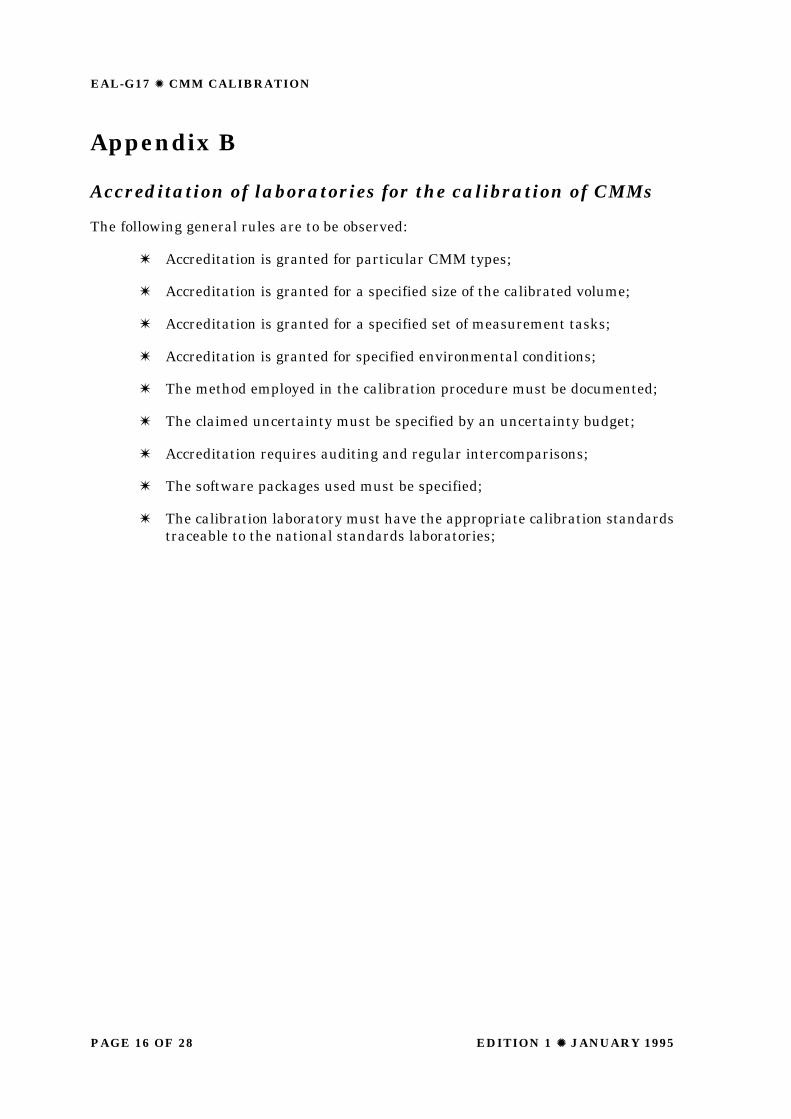
Appendix B
Accreditation of laboratories for the calibration of CMMs
The following general rules are to be observed:
W Accreditation is granted for particular CMM types;
W Accreditation is granted for a specified size of the calibrated volume;
W Accreditation is granted for a specified set of measurement tasks;
W Accreditation is granted for specified environmental conditions;
W The method employed in the calibration procedure must be documented;
W The claimed uncertainty must be specified by an uncertainty budget;
W Accreditation requires auditing and regular intercomparisons;
W The software packages used must be specified;
W The calibration laboratory must have the appropriate calibration standardstraceable to the national standards laboratories;
PAGE 17 OF 28EDITION 1 Z Z JANUARY 1995
EAL-G17 Z CMM CALIBRATION
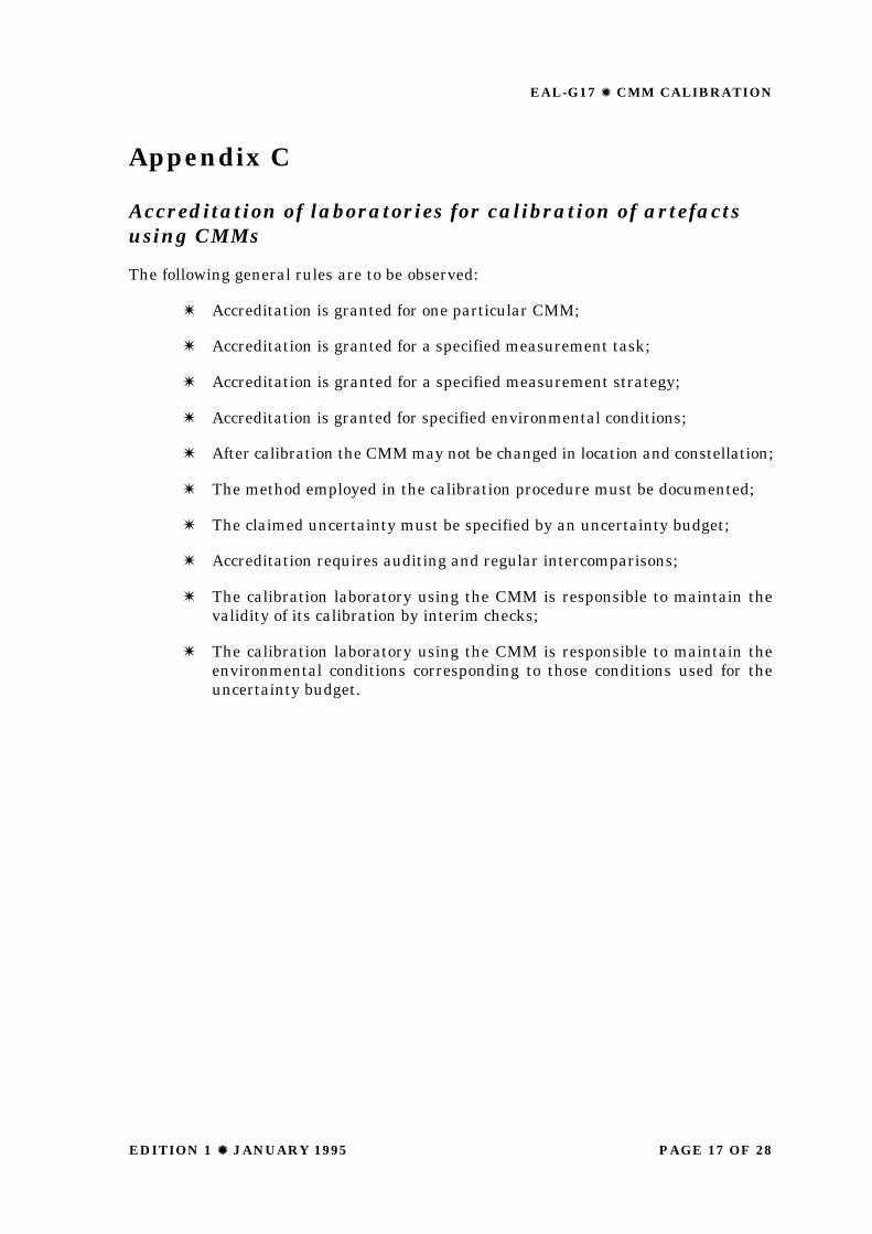
Appendix C
Accreditation of laboratories for calibration of artefactsusing CMMs
The following general rules are to be observed:
W Accreditation is granted for one particular CMM;
W Accreditation is granted for a specified measurement task;
W Accreditation is granted for a specified measurement strategy;
W Accreditation is granted for specified environmental conditions;
W After calibration the CMM may not be changed in location and constellation;
W The method employed in the calibration procedure must be documented;
W The claimed uncertainty must be specified by an uncertainty budget;
W Accreditation requires auditing and regular intercomparisons;
W The calibration laboratory using the CMM is responsible to maintain thevalidity of its calibration by interim checks;
W The calibration laboratory using the CMM is responsible to maintain theenvironmental conditions corresponding to those conditions used for theuncertainty budget.
EAL-G17 Z CMM CALIBRATION
EDITION 1 Z Z JANUARY 1995PAGE 18 OF 28
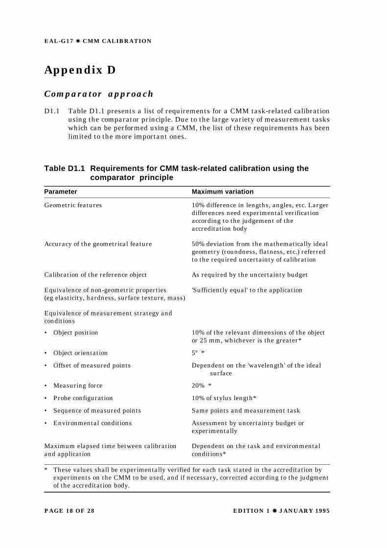
Appendix D
Comparator approach
D1.1 Table D1.1 presents a list of requirements for a CMM task-related calibrationusing the comparator principle. Due to the large variety of measurement taskswhich can be performed using a CMM, the list of these requirements has beenlimited to the more important ones.
Table D1.1 Requirements for CMM task-related calibration using thecomparator principle
Parameter Maximum variation
Geometric features 10% difference in lengths, angles, etc. Largerdifferences need experimental verificationaccording to the judgement of theaccreditation body
Accuracy of the geometrical feature 50% deviation from the mathematically idealgeometry (roundness, flatness, etc.) referredto the required uncertainty of calibration
Calibration of the reference object As required by the uncertainty budget
Equivalence of non-geometric properties 'Sufficiently equal' to the application(eg elasticity, hardness, surface texture, mass)
Equivalence of measurement strategy andconditions
• Object position 10% of the relevant dimensions of the objector 25 mm, whichever is the greater*
• Object orientation 5º *
• Offset of measured points Dependent on the 'wavelength' of the idealsurface
• Measuring force 20% *
• Probe configuration 10% of stylus length*
• Sequence of measured points Same points and measurement task
• Environmental conditions Assessment by uncertainty budget orexperimentally
Maximum elapsed time between calibration Dependent on the task and environmentaland application conditions*
* These values shall be experimentally verified for each task stated in the accreditation byexperiments on the CMM to be used, and if necessary, corrected according to the judgmentof the accreditation body.
PAGE 19 OF 28EDITION 1 Z Z JANUARY 1995
EAL-G17 Z CMM CALIBRATION
D1.2 The environmental conditions, in particular temperature, have a significantinfluence on the error sources of a CMM. The thermal conditions during themeasurement of the reference artefact are to be recorded. These conditions aredefined as the reference conditions. It is assumed that each deviation from thereference conditions adds to the measurement uncertainty of the CMM. Limitsconcerning the difference between the reference conditions and the actualconditions during the measurements shall be stated in the calibration certificate.These limits can be assessed by means of uncertainty budgets or experiments(eg, by re-measuring the reference artefacts under typical environmentalconditions). The user of a CMM is responsible to guarantee the operation of theCMM within the stated limits. Generally it is recommended to measure thereference artefact before and after the object(s) to be calibrated.
EAL-G17 Z CMM CALIBRATION
EDITION 1 Z Z JANUARY 1995PAGE 20 OF 28
Appendix E
Error synthesis approach
E1 Assessment of the CMM’s parametric errors
E1.1 Spatial errors are errors in the measured position of a point on the surface ofthe workpiece as obtained using a particular probing strategy, under specifiedenvironmental conditions. These errors are influenced by:
W the lack of perfection associated with the hardware components of the CMM,for example the CMM guideways, the angular- and linear-displacement-measuring system and the characteristics of the probe system;
W the environment within which the CMM is sited, for example the ambienttemperature, temperature gradients (both in time and space), humidity andvibrations;
W the probing strategy, which encompasses such factors as: the magnitudeand direction of the probe measuring force, the type of probe stylus andsphere used, and the measuring speed of the probe;
W the reference artefacts to qualify the probe;
W the workpiece characteristics, for example the elasticity, surface roughness,hardness and mass.
E1.2 There is no ready-to-use reference with which the errors of all positions of a 3Dmeasuring instrument can be directly determined in all the six degrees offreedom in each position of the CMM’s workspace (orientation errors have to bedetermined in order to analyse Abbé errors due to the various possibleconfigurations of the probe styli). This is why for the present one can do nothingelse except measure all the individual errors associated with each of the axes ofa CMM and the probe system. These errors are called parametric errors andare combined analytically to calculate the errors in the measured coordinatesof each measured point. The type of equations involved in such a computationcan be found in the technical literature.
E1.3 In general, for each CMM axis there are six parametric errors to be measuredas function of the axis position. Furthermore, a squareness error must bedetermined for each pair of axes, yielding an overall total of 21 parametric errorsfor a CMM with three linear axes. The techniques currently used to determinethe parametric errors can be divided into two groups:
W direct measurements which use conventional measuring equipment andartefacts, such as a laser interferometer, electronic levels, a straight edgeand a square to individually measure each parametric error;
W indirect measurements which use the differences between the indicatedvalues and the calibrated values of features on reference artefacts, such asring gauges, holeplates, space frames and step gauges in a multiplicity oflocations throughout the complete work space of the CMM. From thesedifferences the CMM’s parametric errors can be estimated. Also uncalibratedartifacts can be used for this purpose, in which case the variations in themeasurands obtained in different artifact locations are used in the
PAGE 21 OF 28EDITION 1 Z Z JANUARY 1995
EAL-G17 Z CMM CALIBRATION
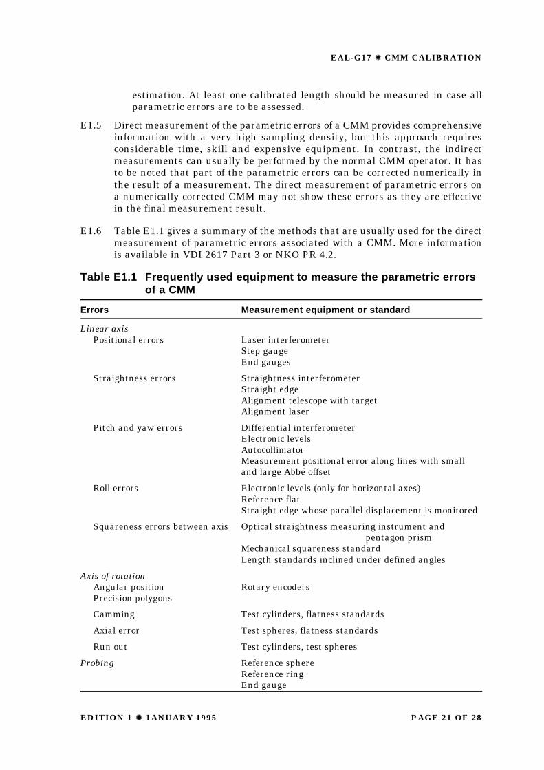
Table E1.1 Frequently used equipment to measure the parametric errorsof a CMM
Errors Measurement equipment or standard
Linear axisPositional errors Laser interferometer
Step gaugeEnd gauges
Straightness errors Straightness interferometerStraight edgeAlignment telescope with targetAlignment laser
Pitch and yaw errors Differential interferometerElectronic levelsAutocollimatorMeasurement positional error along lines with smalland large Abbé offset
Roll errors Electronic levels (only for horizontal axes)Reference flatStraight edge whose parallel displacement is monitored
Squareness errors between axis Optical straightness measuring instrument andpentagon prism
Mechanical squareness standardLength standards inclined under defined angles
Axis of rotationAngular position Rotary encodersPrecision polygons
Camming Test cylinders, flatness standards
Axial error Test spheres, flatness standards
Run out Test cylinders, test spheres
Probing Reference sphereReference ringEnd gauge
estimation. At least one calibrated length should be measured in case allparametric errors are to be assessed.
E1.5 Direct measurement of the parametric errors of a CMM provides comprehensiveinformation with a very high sampling density, but this approach requiresconsiderable time, skill and expensive equipment. In contrast, the indirectmeasurements can usually be performed by the normal CMM operator. It hasto be noted that part of the parametric errors can be corrected numerically inthe result of a measurement. The direct measurement of parametric errors ona numerically corrected CMM may not show these errors as they are effectivein the final measurement result.
E1.6 Table E1.1 gives a summary of the methods that are usually used for the directmeasurement of parametric errors associated with a CMM. More informationis available in VDI 2617 Part 3 or NKO PR 4.2.
EAL-G17 Z CMM CALIBRATION
EDITION 1 Z Z JANUARY 1995PAGE 22 OF 28
E1.7 In order to avoid misinterpretation of the translational error components dueto Abbe effects, the positional, squareness and straightness errors must bepresented along specified lines in the workspace of the CMM. This can beachieved by measuring these errors along those lines or by correcting thetranslational errors for the Abbé effect by the measured rotational errors.
E1.8 It is recommended that the probing error is assessed for each probe configurationused to carry out measurements with the calibrated CMM. Each probe tip isset up and qualified using the same procedure as when performing measure-ments with the CMM. The probing error is determined by the measurement ofat least 40 points on a calibrated reference sphere, in a nearly uniformdistribution over a full hemisphere.
E1.9 For some task related calibrations, the evaluation of the probing system mightbe limited to its 1D or 2D errors. In those cases, the probing errors can bedetermined using end standards, for example gauge blocks, and the referencesphere mentioned.
E1.10 In the calibration certificate, the measured parametric errors as well as all otherresults have to be stated with their uncertainties. These uncertainties are relatedto the repeatability of the CMM, the uncertainty of the calibration equipmentused, the sampling density, the effect of thermal errors and the effects of thefinite stiffness of components, which has an important influence on the validityof the rigid body model.
E2 Calculation of the errors in the measured position of a point
E2.1 In this section the parametric errors are combined to calculate the errors of themeasured points. Two techniques or a combination of both can be used:
W Numerical simulation: the parametric errors at the studied position ofthe CMM axes are calculated by interpolation or regression of thecorresponding measurement data. The errors in the measured coordinatesof the probe-tip of the CMM are then calculated as the sum of the varioustranslational errors and angular errors, the latter multiplied with theappropriate Abbé offsets.
W Statistical analysis: the parametric errors of a CMM are treated as randomvariables. In accordance with the WECC document 19 (EAL-G1), theuncertainty of the measured coordinates is calculated from a) the statisticaldescription of the measurement data used to derive the parametric errorsand, b) a model for their effect on the computed coordinates.
E3 Assessment of the errors in the measured feature
E3.1 One of the most important tasks for the CMM software is to determine theworkpiece geometry from a set of measured point coordinates. This processintroduces and transforms the errors in the measured point coordinates to errorsin the estimated features. In the calibration of a CMM, two effects of thistransformation have to be considered:
PAGE 23 OF 28EDITION 1 Z Z JANUARY 1995
EAL-G17 Z CMM CALIBRATION
W the (mathematically pure) propagation of errors. This results in errors inthe estimated feature that can be explained fully by the errors in themeasured coordinates of the points in association with the properties of theestimation principle used (for example, the Gaussian or Chebyshev methods),
W the introduction of errors due to the limited accuracy of the software-computer combination of the CMM. This yields errors in the estimatedgeometry of the workpiece that cannot be explained by the mathematicallypure propagation of errors.
E3.2 The following approach is suggested (although other approaches may be possible)to calculate the task-related errors of a CMM, including the above effects.
W The CMM software is tested for example using data-sets for which a provensolution is available. These tests should guarantee that the errors introducedby the respective software and computer can be neglected compared to theerrors introduced by the CMM. Data sets of this kind are available for someestimation tasks (especially to test the estimation of geometrical primitives).It is worth noting that these tests have to be performed only once for eachrevision of the software. The errors in the estimated workpiece’s geometrycan now be evaluated by comparing the geometry estimated with:
(a) the nominal point coordinates and
(b) the nominal coordinates plus the appropriate error vectors of theprobing points.
The uncertainty of the result can be evaluated using Monte Carlo techniquesto model the variation of the error vector of the measured coordinates.
E3.3 Using this approach it is possible to determine the accuracy of a certainmeasurement task. Other measurement tasks can be evaluated, usually withthe same parametric error data. Using appropriate software (eg a virtual CMM),this simulation can usually be performed by a computer. Thus it is possible toextend the application area of the calibration as described in Section 4, bysimulating many measurement tasks. A typical example of this approach is the'brute force' evaluation of the length-measurement capability of a CMM, bycalculating the accuracy of many (say, 10 000) length measurements simulatedthroughout various locations in the workspace of a CMM.
E4 Special problems of CMM calibrations
E4.1 Temperature distribution of the CMM
E4.1.1 The environmental conditions associated with CMMs, in particular temperature,significantly influence the sources of errors of a CMM.
E4.1.2 It is strongly recommended that the thermal conditions (average environmentaltemperature and spatial gradients) are recorded during the calibrationprocedure. These conditions are defined as the reference conditions, ie theconditions to which the calibration is referred.
EAL-G17 Z CMM CALIBRATION
EDITION 1 Z Z JANUARY 1995PAGE 24 OF 28
E4.1.3 It is assumed that each departure from these reference conditions adds to themeasurement uncertainty of the CMM. Hence additional margins in theuncertainty budget for each measurement task must be expected, allowing thetemperature distribution in the CMM and in its environment to vary withincertain limits, and allowing for certain errors in the CMM’s own temperaturemeasuring system (if applicable). The user of the CMM is responsible to keepthe temperature distribution inside the stated limits.
E4.2 Redundant axes
E4.2.1 Many CMMs have more than 3 linear axes, for example a rotary table, a CNC-controlled probe head, or a dual arm configuration.
E4.2.2 Purely comparator-type calibrations do not need error models of the CMM, andhence their application to component measurement is straightforward even forCMMs with redundant axes.
E4.2.3 Any simulation requires precise specification of the axes positions used to realizethe probe position, because a single point may be reached in an infinity of waysby a combination of redundant axes.. This can be illustrated by the example ofa CMM that has a high-accuracy rotary table, and a Cartesian system withlarge systematic errors but with good reproducibility. This measuring systemcan achieve excellent results as well as very poor results, depending upon themeasurement strategy employed.
E4.3 CMMs with non-rigid-body behaviour
E4.3.1 Not all mathematical models nor all assessment techniques can determine theinfluence of the errors associated with the axes of motion which depend on theposition of other axes. This typically is the case with horizontal arm CMMs.Comparator-type calibrations automatically include these effects.
E4.4 Stability
E4.4.1 A CMM’s parametric errors can change in time (eg due to collisions or wear).This requires methods for the quick, easy and hence frequently performedassessment of the CMM stability. This assessment is the responsibility of theCMM user.
E4.4.2 1D, 2D and 3D artefacts are well suited to assess CMM stability. As only changesin parametric errors have to be detected, a few datum points along each CMMaxis are sufficient to assess the stability of the CMM. The first stabilityassessment should be performed immediately after the calibration. Subsequentreassessments are compared with this result. A new calibration is required ifthe observed changes exceed those changes taken into account in the uncertaintybudget.
E4.5 Large CMMs
E4.5.1 Large CMMs pose several additional problems including:
W the use of large artefacts is a problem because of their availability, thedifficulties associated with their handling, temperature problems and theextended time needed for measurements.
PAGE 25 OF 28EDITION 1 Z Z JANUARY 1995
EAL-G17 Z CMM CALIBRATION
W changes in the foundations can limit the stability of large machines. Theseeffects are to a significant extent dependent upon the installation of a specificCMM and are therefore difficult to predict and hence to model. Anycalibration of a large CMM should therefore include long term studies of itsstability (see Section E4.4).
E4.6 CMMs with numerical error correction
E4.6.1 Not all parametric errors of CMMs with numerical error correction can beassessed by direct measurement methods, such as laser interferometry, levelmeters or autocollimators. The reason is that the correction is applied to themeasured data rather than to the geometrical form of the carriages of the CMMs.Hence the effect of an often unknown part of the measured parametric errormay be corrected in the software or controller of the CMM. For this reason oneusually has to use measurements on artefacts to extract the uncorrected, andhence effective, part of the parametric errors.
E5 Example - the PTB method of determining parametric errors frommeasurements on 2D reference artefacts
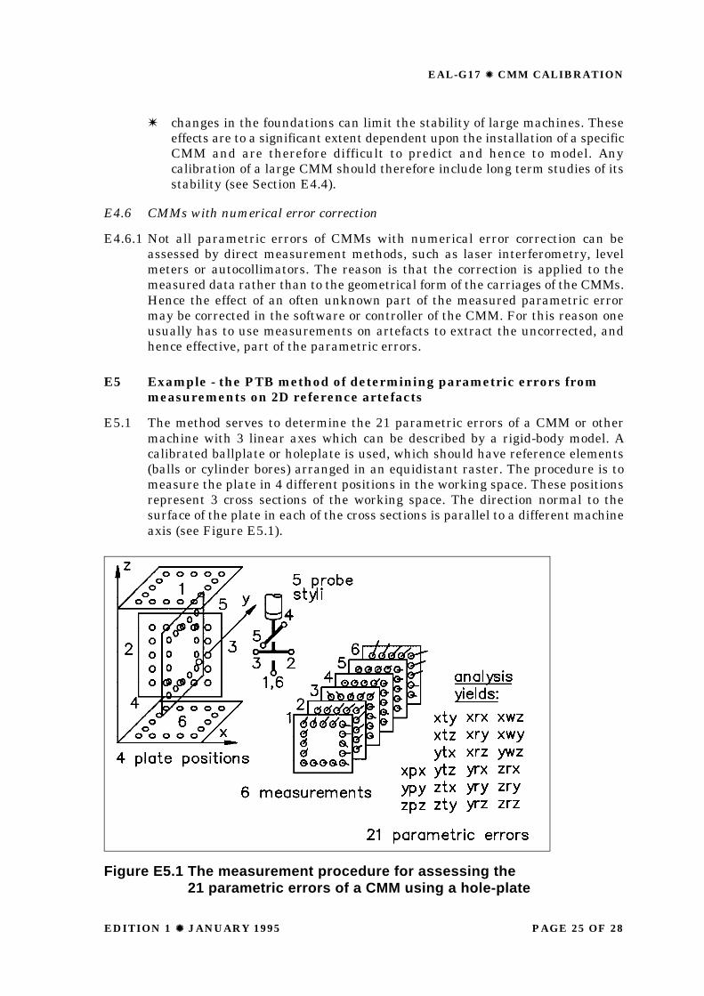
E5.1 The method serves to determine the 21 parametric errors of a CMM or othermachine with 3 linear axes which can be described by a rigid-body model. Acalibrated ballplate or holeplate is used, which should have reference elements(balls or cylinder bores) arranged in an equidistant raster. The procedure is tomeasure the plate in 4 different positions in the working space. These positionsrepresent 3 cross sections of the working space. The direction normal to thesurface of the plate in each of the cross sections is parallel to a different machineaxis (see Figure E5.1).
Figure E5.1 The measurement procedure for assessing the21 parametric errors of a CMM using a hole-plate
EAL-G17 Z CMM CALIBRATION
EDITION 1 Z Z JANUARY 1995PAGE 26 OF 28
E5.2 With the plate parallel to each coordinate plane, 2 measurements are performedso that different effective distances from the coordinate axes are obtained, eitherby shifting the plate (parallel to itself) or by using 2 different probe styli. Thisresults in 2 parallel positions which are normal to the third kinematic axis (ram),and two further positions, one where the plate is parallel to the first, and onewhere it is parallel to the second kinematic axis.
E5.3 From the 6 sets of measurements the 18 error functions, corresponding to the 3times 6 degrees of freedom of three axes of motion, are determined by a fittingalgorithm. The density of data points obtained is the same as the raster spacingon the plate. The 3 squareness errors are also estimated.
The accuracy of the method is determined by the:
W calibration uncertainty of the plate, which is currently 0.7 µm for a 0.5 m2
plate,
W stability of the CMM,
W reproducibility of the CMM,
W validity of the rigid body model for the CMM.
PAGE 27 OF 28EDITION 1 Z Z JANUARY 1995
EAL-G17 Z CMM CALIBRATION
Appendix F
Recommendations for future developments
F1 Intercomparison of methods to assess the error components of CMMs
F1.1 The availability of easy to handle and not costly methods is an indispensableprerequisite for the successful implementation of calibration methods. Theintercomparison shall compare existing 'state-of-the-art' as well as 'proven'methods. All interested European laboratories should be invited for thisintercomparison.
F2 Study about artefacts suited for the assessment of the errorcomponents of CMM
F2.1 It is often very difficult to judge the qualities of mechanical reference artefactsbecause there are so many different and often conflicting requirements, forexample:
W price;
W handling (ease, speed);
W potential accuracy of their calibration;
W calibration cost;
W suitability for other, lower level, CMM-checks to minimise investment;
W the amount of information about the CMM-errors obtained per probed point;
W mechanical long-term stability; and
W thermomechanical behaviour.
F2.2 An intercomparison of suitable artefacts is suggested. This shall serve threepurposes:
W the improvement of the laboratories’ capability for the calibration of theartefacts,
W to gain practical experience about the stability of the artefacts,
W the standardization of artefacts.
EAL-G17 Z CMM CALIBRATION
EDITION 1 Z Z JANUARY 1995PAGE 28 OF 28
F3 Development of methods for the assessment of task-related errors
F3.1 An international cooperation project on the development of methods for task-related error analysis is recommended. This project shall fulfil the followingtasks:
W study the possibility of an a priori error analysis, i.e. the analysis of task-related errors to be expected during a measurement. This analysis shall bedone when defining the measurement task.
W study the possibility of an error analysis which is integrated in the CMM’scomputer and cooperates with the CMM’s evaluation software. Thus theuncertainties of the executed measurement tasks are automatically assessed.
F4 Data bank of CMM errors
F4.1 A data bank with the errors of CMMs studied by the collaborating laboratoriesshall be set up. This will have the advantage that:
W results can be compared;
W a statistically meaningful number of CMM error sets are available to testthe error assessment methods on real data;
W information on errors and stability of a large number of CMMs will becomeavailable;
W the handling of the data bank will stimulate the exchange of experiencebetween laboratories.
F5 Development of methods for the assessment and modelling of probingerrors
F6 Development of methods for the assessment and modelling of rotarytable errors
F7 Development of methods for the assessment and modelling of theelastic behaviour of CMMs