Embed Size (px)
Citation preview
Leave footer empty – The Conference footer will be added to the first page of each paper.
EARLY PHASE RE-ENTRY ANALYSIS OF ESA EARTH
OBSERVATION MISSIONS TO ADVANCE SATELLITE DESIGN
CHOICES
Carmen Velarde(1), Charlotte Bewick(2), Mark Fittock(3), Simone Flavio Rafano Carná (4)
OHB System AG, Universitätsallee 27-29, D-28359 Bremen, Germany, (1)[email protected], (2)[email protected], (3)[email protected], (4)[email protected]
ABSTRACT
At OHB System, a large effort is invested to design
satellites which comply with the new Clean Space Policy
and Space Debris Mitigation Guidelines. This paper
provides the outcome of the re-entry analysis performed
during the early phases of satellite missions at OHB,
within the Space Systems Studies department. In
specific, the re-entry analysis of different Earth
observation satellites are presented, which have been the
drivers of design decisions between uncontrolled and
controlled deorbit strategies. In view of the system
implications, an uncontrolled re-entry strategy is often
the preferred option. In specific, the disposal strategy is
driver for the selection of the propulsion system and
launcher. Thus, an overview of the factors with greatest
impact on the demisability of the satellite components is
here presented, together with the different Design for
Demise strategies proposed to achieve compliance with
the 1/10000 casualty risk threshold. General conclusions
between the different satellite systems are drawn,
differentiating between radar and optical payloads, and
between chemical and electric propulsion systems.
Missions that cannot achieve the casualty threshold need
to plan a controlled re-entry targeting the debris impact
over unpopulated areas to minimize the casualty risk for
human population.
1 INTRODUCTION
In the early phases of Earth Observation (EO) missions,
the disposal strategy is highly interconnected with system
level trade-offs for selection of the propulsion system and
launcher. VEGA-C is the baseline launcher for the recent
ESA EO missions, which is for large satellite systems a
design driver. A higher dry mass can be achieved by
performing an electric raising manoeuvre from a low
injection orbit. However, a chemical propulsion system
is required for performing a controlled re-entry. An
uncontrolled re-entry is only possible by demonstrating
compliance with the 1/10000 threshold. In the
impossibility of compliance, a hybrid propulsion system
can be considered for satellites demanding a higher mass.
Only then, if launcher performance are not sufficient, a
different baseline launcher is considered. Chapter 3
presents the flow-diagram followed at OHB for the
selection of the disposal strategy, propulsion system and
launcher in recent ESA EO missions.
The roadmap for the selection of the disposal strategy is
presented in Chapter 2. The DRAMA tool from ESA is
the baseline software at OHB for re-entry and casualty
risk analysis. In Chapter 4, the methodology of the
computation is summarized.
The break-up altitude is a paramount design parameter
for the demisability of the components. This is retrieved
with dedicated Monte Carlo simulations, considering the
default thermal criterion as the trigger for the spacecraft
fragmentation.
Guidelines from ESA are followed for the modelling of
the spacecraft, presented in Chapter 5. However, there is
quite an uncertainty for the modelling of components
such as CFRP panels and electronic units. The default
CFRP model from DRAMA seems not representative for
structural panels, and thus material properties from
reference are considered for comparison. Casualty risk
analysis results from different EO missions analysed at
OHB are presented in Chapter 6. Surviving components
from platform and payload are highlighted,
differentiating between radar and optical missions, and
chemical and electric propulsion systems. Given the large
impact the demise of CFRP panels have on the casualty
risk budget, a research on dedicated CFRP test campaigns
is carried out to understand their demisability at
spacecraft re-entry.
Design for demise solutions (D4D) can be applied to
reduce the casualty risk. For missions at the edge of
compliance, considering containment solutions such as
tethers joining bipods, or demisable reaction wheels has
led to compliance with casualty risk threshold to perform
an uncontrolled re-entry.
Finally, in the impossibility for performing an
uncontrolled re-entry, a controlled re-entry shall be
considered. To minimize the delta-V cost for performing
the final burn, the highest perigee altitude that allows the
debris footprint area to fit within the target area (i.e.:
South Pacific Ocean Uninhabited Area) is assessed in
Chapter 8. A perigee altitude around 70km results as the
threshold value for the missions analysed.
Proc. 8th European Conference on Space Debris (virtual), Darmstadt, Germany, 20–23 April 2021, published by the ESA Space Debris Office
Ed. T. Flohrer, S. Lemmens & F. Schmitz, (http://conference.sdo.esoc.esa.int, May 2021)
Leave footer empty – The Conference footer will be added to the first page of each paper.
2 ROADMAP TO SELECTION OF
DISPOSAL STRATEGY
At the end of mission, satellites shall be placed out of the
LEO clearance region within 25 years, in compliance
with ISO 24113 and ESA Space Debris Mitigation
(SDM) requirements defined by the ESA policy
ESA/ADMIN/IPOL(2014)2 [1].
The end of life assessment aims to identify the most
suitable de-orbiting solution for the mission. In order to
avoid the need to rely on de-orbiting services (i.e. space
tugs), the satellite will have to de-orbit by its own means.
Different de-orbiting solutions exist, mainly the satellite
can be de-orbited with a controlled or an uncontrolled re-
entry. With the update in 2019 of the ISO 24113, the
disposal to a graveyard orbit above the LEO region is no
longer permitted. The selection driver between a
controlled or uncontrolled disposal strategy is the
resulting casualty risk, which shall comply with the
1/10000 threshold. The trade on the disposal scenario is
driver for the mission, as strongly impacts the required
propellant to be stored on-board, as well as the required
propulsion system, and consequently, the launcher
selection.
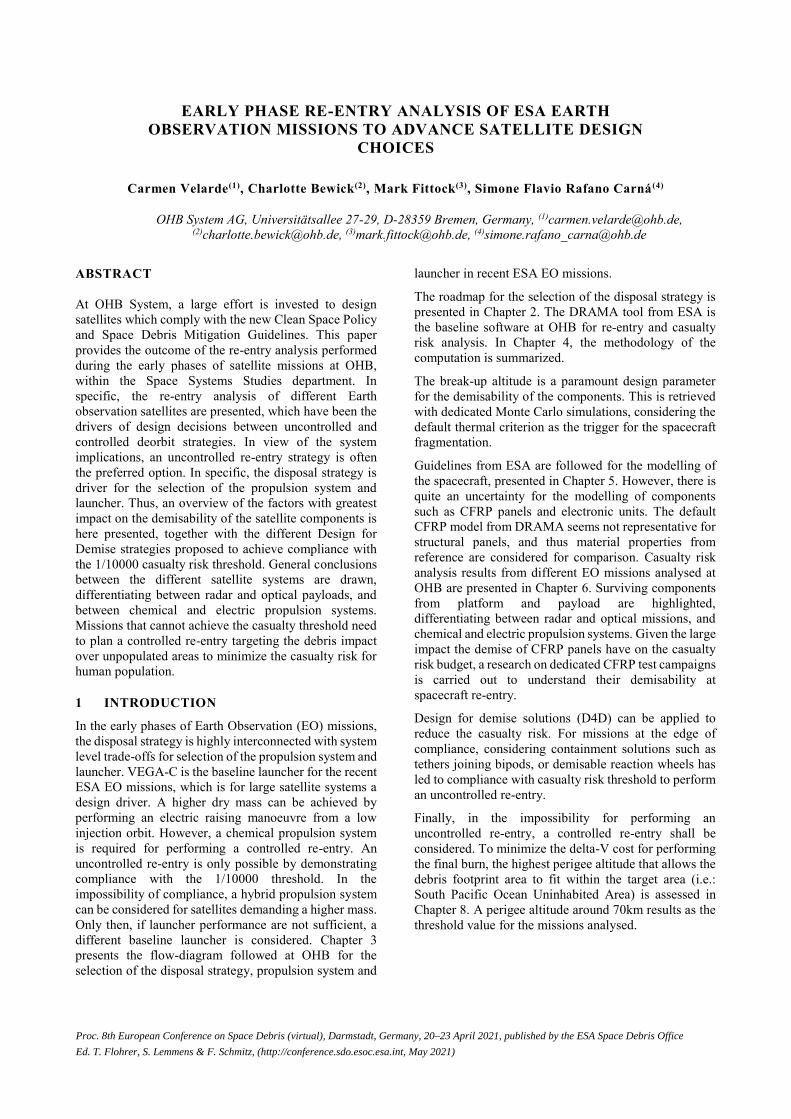
The following diagram shows the common process
followed for disposal manoeuvre selection of LEO
satellites. The atmospheric re-entry is achievable through
either propulsive means or passively through
atmospheric drag. The satellite decay period and the
compliance to casualty risk are the deciding factors.
Figure 1. Process for selection of orbital disposal
strategy for LEO spacecraft
The DRAMA-SARA tool from ESA is used to calculate
the satellite components which may survive and to
compute the casualty risk for both the controlled and
uncontrolled scenarios. The casualty risk is highly
impacted by the re-entry year. It increases with the world
population. The survivability of the components is
significantly related to the break-up altitude of the main
parent. A 78km is commonly approved by the Agency,
however, following the ESA Space Debris Mitigation
Guidelines [1], the prediction of the break-up altitudes
can be based on valid physical considerations, similitudes
or probabilistic assessments. Dedicated analysis are
performed for this purpose (Chapter 6).
Mainly large and high melting temperature components
survive re-entry. Design for demise solutions (D4D) can
be applied to reduce the casualty risk. There exist
different solutions, with the aim of reducing the casualty
area (e.g.: containment tethers), accelerating the break-up
altitude (e.g.: new structural joining technologies) or
replacing components with other of higher demisability
materials.
In case of compliance with the 1/10000 threshold, the
orbit decay is analysed to assure the satellite re-enters
within 25 years. The satellite is manoeuvred down to a
perigee altitude from which, after 25 years, it will re-enter
into the atmosphere.
On the other hand, in the impossibility to comply with
casualty risk requirement by means of an uncontrolled
disposal strategy, a controlled re-entry scenario shall be
planned to target the debris impact over unpopulated
areas (i.e. SPOUA: South Pacific Ocean Uninhabited
Area). A controlled re-entry scenario requires a larger
Delta-V demand and therefore higher propellant mass.
Moreover, the final boost will require a high thrust not
achievable by means of electric propulsion.
In a controlled re-entry scenario, a Monte Carlo
campaign is conducted to simulate the uncertainties of
the final boost and estimate debris footprint area. In
Chapter 8, targeting a perigee altitude around 60km is
shown to guarantee the footprint size to fit within the
SPOUA.
3 SYSTEM IMPACTS OF DISPOSAL
STRATEGY SELECTION
In the early phases of Earth Observation satellite
missions, the disposal strategy is highly interconnected
with system trade-offs for selection of the propulsion
system and launcher.
As required by the Agency in most cases of the recent EO
missions, VEGA-C shall be the baseline launcher.
Examples are the Copernicus expansion missions like
CO2M, LSTM and PICE satellites, Earth Explorer
missions as SKIM, Harmony, Forum, Hydroterra and the
Next Generation Sentinel satellites. For large satellite
systems, this might be a challenging requirement given
the performance of the launcher.
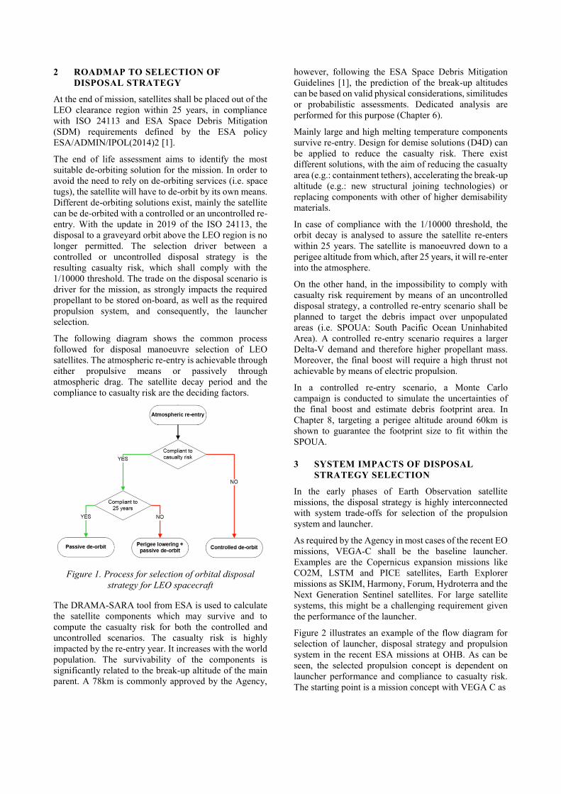
Figure 2 illustrates an example of the flow diagram for
selection of launcher, disposal strategy and propulsion
system in the recent ESA missions at OHB. As can be
seen, the selected propulsion concept is dependent on
launcher performance and compliance to casualty risk.
The starting point is a mission concept with VEGA C as
Leave footer empty – The Conference footer will be added to the first page of each paper.
Figure 2. Impact of Disposal Strategy on Launcher and Propulsion System Selection (Example from recent ESA mission
at OHB)
baseline launcher, and a chemical system with
uncontrolled re-entry to simplify the satellite system.
However, an uncontrolled manoeuvre is only possible by
demonstrating the casualty risk at impact is less than
1/10000. With the required propellant mass for
performing a controlled manoeuvre, the remaining
satellite dry mass with a VEGA-C launch might be
compromised. For instance, an estimation of the top-
down mass breakdown for a representative SSO at
800km, with VEGA-C performance of 2080kg [2], is
provided in Table 1. This shows the remaining satellite
dry mass is ~1790 kg.
For large satellite systems requesting higher launch mass,
changing the baseline launcher is left as the very last
option. Instead, a full-electric propulsion system is first
analysed. With a launch to a low SSO orbit at 500km
altitude, VEGA-C performance is of 2.4 tones [2]. With
a full-EP system, the spacecraft will then perform an
electric orbit raising up to the nominal orbit. Following
with the previous example of the representative SSO orbit
at 800km, Table 1 shows the remaining satellite dry mass
can be increased up to 2240kg. In the impossibility of
compliance with the casualty risk threshold, a hybrid
propulsion system for performing the final burn is
considered. Finally, missions requiring larger satellite
dry masses, a launcher offering higher performance shall
be considered.
Table 1. Top down mass breakdown for best and worst
case dry mass scenarios for a SSO at 800km
Top-down mass
breakdown
Mass [kg]
Chemical
Controlled
Mass [kg]
EP
Uncontrolled
Launcher
performance
2080
(@800km) 2380 (@500km)
LVA 95 95
Spacecraft wet
mass 1985 2285
Propellant
mass 197* 46**
Spacecraft dry
mass 1788 2239
( *) Launcher dispersions + 60km targeted perigee, 220s Isp
( **) Raising and lowering manoeuvre to 800km, 1600s Isp
Mission Concept:
Chemical Propulsion
Uncontrolled Reentry
S/C dry mass
Launcher performance sufficient for full chemical
solution?
Uncontrolled reentry
Mission Concept:
Hybrid Propulsion
Controlled Reentry
Full E
P
Full ch
em
ical
Mission Concept:
Electrical Propulsion
Uncontrolled Reentry
Mission Concept:
Chemical Propulsion
Controlled Re-entry
No
Controlled reentry No
Launcher performance sufficient for full chemical
solution?
Full ch
em
ical
No
Hybrid:Change to EP and use CP only for final burn
Yes
Compliance to casualty risk of 10^-4?
Yes
Chemical Propulsion
Uncontrolled reentry
Launcher: Vega-C
Yes
Launcher performance sufficient for hybrid
solution?
Yes
No Launcher performance sufficient for full electrical
solution?
Yes
Backup Launcher: Ariane 6.2
or Ariane 6.4
Iteration
No
Still compliance to casualty risk of 10^-4?
Yes
Hybrid: Add CP for final burn
No
Leave footer empty – The Conference footer will be added to the first page of each paper.
4 CASUALTY RISK ANALYSIS
METHODOLOGY AT OHB
The DRAMA tool from ESA is used to calculate the
components of satellite models which may survive the re-
entry and to compute the casualty risk for an uncontrolled
and a controlled scenario. The SARA module of
DRAMA executes the re-entry survival and risk analyses
in two steps using the following tools: SESAM (to assess
re-entry survival) and SERAM (to assess re-entry risk).
The updated version of DRAMA allows defining
relationships between the spacecraft components. A main
parent has to be defined, then the rest of components can
be included in or connected to it. The main parent is
defined as Platform Module, which has an equivalent box
shape to the external shape of the spacecraft structure. All
units contained in the spacecraft bus will be included and
the external units will be connected to it, as the payload
housing (with connected and included payload children),
antennas and the launcher adapter.
Components are modelled with simplified shapes (boxes,
spheres, cylinders and cones), each composed of a single
material characterised by density, melting point, specific
heat capacity, heat of fusion and emissivity. Default
properties from DRAMA database are used when
available.
Surviving fragments are identified and added to the
casualty area budget. The kinetic energy threshold
criterion of 15-Joules (accepted as the minimum level for
potential injury to an unprotected person) is applied to
filter surviving components in the casualty risk budget.
The survivability of the components is significantly
related to the break-up altitude of the main parent. The
higher the break-up altitude, the earlier the exposure of
the children to the flow and the longer the time these have
to reach a higher temperature. In previous versions of
DRAMA, the break-up altitude was fixed at 78 km. In
this updated version of DRAMA (version 3.0.3) the
break-up altitude can be triggered based on the integrated
time histories of the aerothermodynamics of the fragment
model along the propagated trajectory [3]. The thermal
criterion is the default trigger for the spacecraft
fragmentation. Following the ESA Space Debris
Mitigation Guidelines [1], the prediction of the break-up
altitudes can be based on valid physical considerations,
similitudes or probabilistic assessments.
The re-entry analysis at OHB is performed in two phases.
Based on the default criterion of DRAMA (total demise
of the parent primitive), a first analysis is performed to
estimate the worst-case break-up altitude of the main
parent. The survivability and casualty risk analysis is then
performed in a second simulation forcing the break-up of
the main parent at the pre-determined break-up altitude.
The worst-case (i.e.: latest break-up) corresponds to the
mean-3σ altitude resulting from a Monte Carlo campaign
on a simplified model of the spacecraft, with the
uncertainties impacting the spacecraft trajectory.
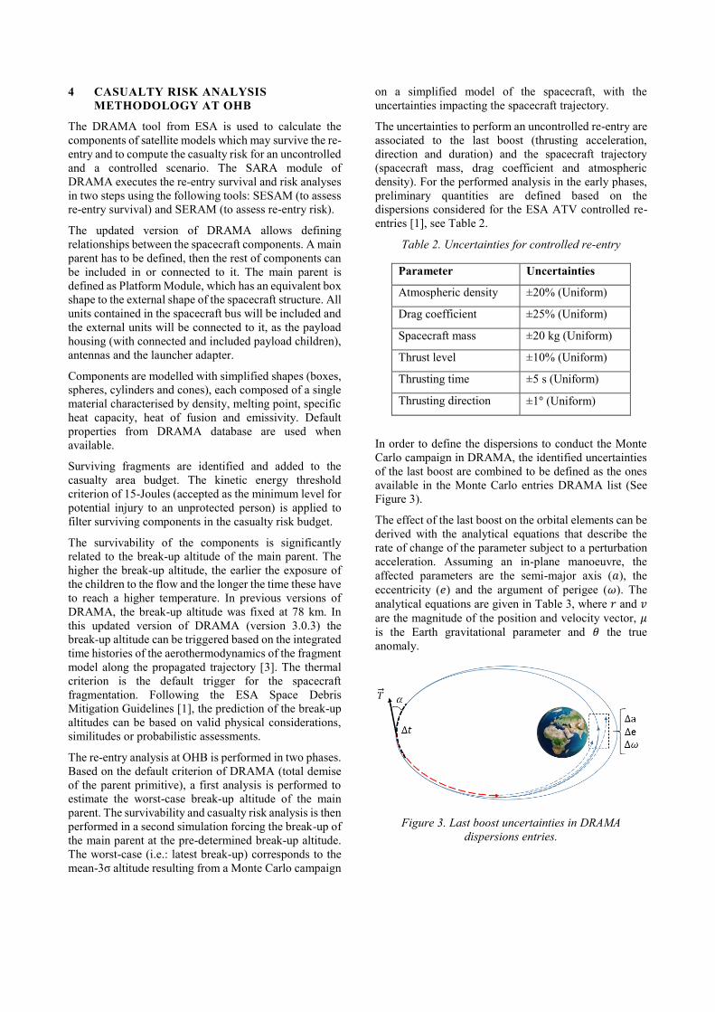
The uncertainties to perform an uncontrolled re-entry are
associated to the last boost (thrusting acceleration,
direction and duration) and the spacecraft trajectory
(spacecraft mass, drag coefficient and atmospheric
density). For the performed analysis in the early phases,
preliminary quantities are defined based on the
dispersions considered for the ESA ATV controlled re-
entries [1], see Table 2.
Table 2. Uncertainties for controlled re-entry
Parameter Uncertainties
Atmospheric density ±20% (Uniform)
Drag coefficient ±25% (Uniform)
Spacecraft mass ±20 kg (Uniform)
Thrust level ±10% (Uniform)
Thrusting time ±5 s (Uniform)
Thrusting direction ±1° (Uniform)
In order to define the dispersions to conduct the Monte
Carlo campaign in DRAMA, the identified uncertainties
of the last boost are combined to be defined as the ones
available in the Monte Carlo entries DRAMA list (See
Figure 3).
The effect of the last boost on the orbital elements can be
derived with the analytical equations that describe the
rate of change of the parameter subject to a perturbation
acceleration. Assuming an in-plane manoeuvre, the
affected parameters are the semi-major axis (𝑎), the
eccentricity (𝑒) and the argument of perigee (𝜔). The
analytical equations are given in Table 3, where 𝑟 and 𝑣
are the magnitude of the position and velocity vector, 𝜇
is the Earth gravitational parameter and 𝜃 the true
anomaly.
Figure 3. Last boost uncertainties in DRAMA
dispersions entries.
Leave footer empty – The Conference footer will be added to the first page of each paper.
Table 3. Rate of change of orbital elements with in-
plane perturbations.
Parameter 𝒇𝒕 𝒇𝒏
𝒅𝒂
𝒅𝒕
2𝑎2
𝜇𝜈 0
𝒅𝒆
𝒅𝒕
2𝑎𝜈𝑟(𝑒 + 𝑐𝑜𝑠𝜃)
𝜇(2𝑎 − 𝑟)
𝑟𝑠𝑖𝑛𝜃
2𝑎𝜈
𝒅𝝎
𝒅𝒕
2𝑎2
𝜇𝜈
2𝑎𝑒 + 𝑟𝑐𝑜𝑠𝜃
2𝑎𝑒𝜈
Given representative characteristics for the last burn, the
dispersions of the three orbital parameters are defined as
the rate of change for the resulting thrusting acceleration,
integrated over the region bounded by the thrusting arc
centered at the apogee. The estimated dispersions are
given in Table 4.
Table 4. Monte Carlo dispersion entries for controlled
re-entry analysis based on representative last burn
characteristics
Parameter Value
Second-to-last Perigee 250 km
Δ𝑉 60 m/s
Duration 26 min
Mean Thrust 50 N
Parameter Uncertainties
Semi-major Axis ±10 km (Uniform)
Eccentricity ± 0.001 (Uniform)
Argument of Perigee ±1° (Uniform)
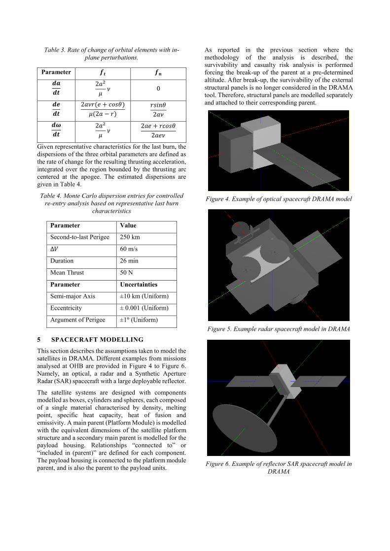
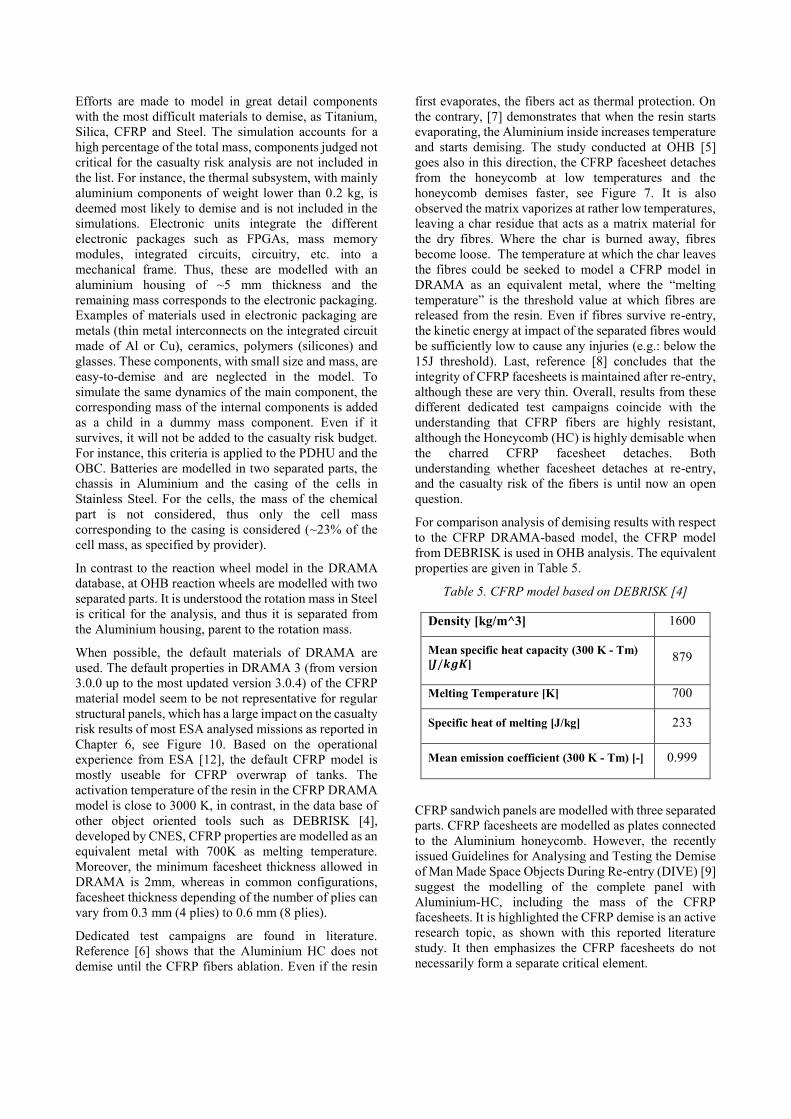
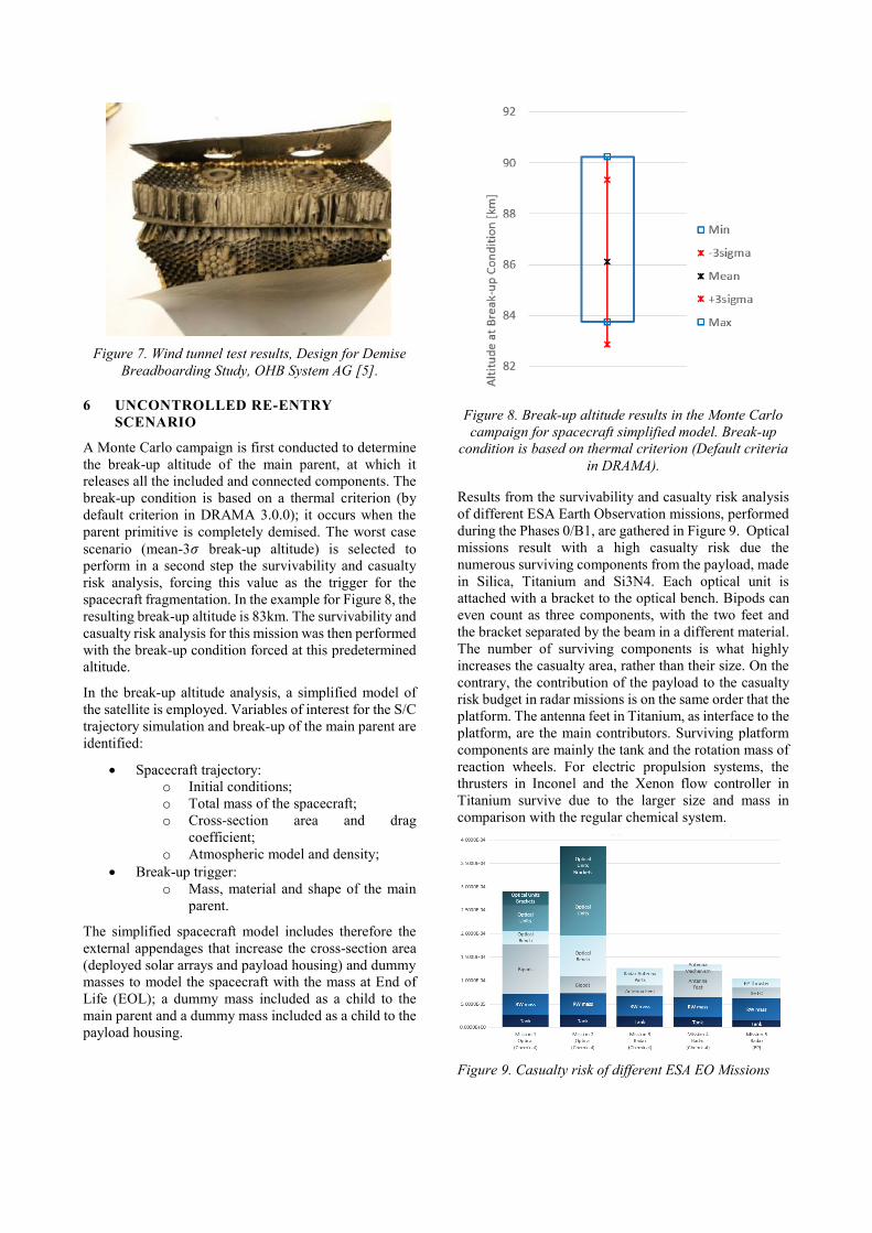
5 SPACECRAFT MODELLING
This section describes the assumptions taken to model the
satellites in DRAMA. Different examples from missions
analysed at OHB are provided in Figure 4 to Figure 6.
Namely, an optical, a radar and a Synthetic Aperture
Radar (SAR) spacecraft with a large deployable reflector.
The satellite systems are designed with components
modelled as boxes, cylinders and spheres, each composed
of a single material characterised by density, melting
point, specific heat capacity, heat of fusion and
emissivity. A main parent (Platform Module) is modelled
with the equivalent dimensions of the satellite platform
structure and a secondary main parent is modelled for the
payload housing. Relationships “connected to” or
“included in (parent)” are defined for each component.
The payload housing is connected to the platform module
parent, and is also the parent to the payload units.
As reported in the previous section where the
methodology of the analysis is described, the
survivability and casualty risk analysis is performed
forcing the break-up of the parent at a pre-determined
altitude. After break-up, the survivability of the external
structural panels is no longer considered in the DRAMA
tool. Therefore, structural panels are modelled separately
and attached to their corresponding parent.
Figure 4. Example of optical spacecraft DRAMA model
Figure 5. Example radar spacecraft model in DRAMA
Figure 6. Example of reflector SAR spacecraft model in
DRAMA
Leave footer empty – The Conference footer will be added to the first page of each paper.
Efforts are made to model in great detail components
with the most difficult materials to demise, as Titanium,
Silica, CFRP and Steel. The simulation accounts for a
high percentage of the total mass, components judged not
critical for the casualty risk analysis are not included in
the list. For instance, the thermal subsystem, with mainly
aluminium components of weight lower than 0.2 kg, is
deemed most likely to demise and is not included in the
simulations. Electronic units integrate the different
electronic packages such as FPGAs, mass memory
modules, integrated circuits, circuitry, etc. into a
mechanical frame. Thus, these are modelled with an
aluminium housing of ~5 mm thickness and the
remaining mass corresponds to the electronic packaging.
Examples of materials used in electronic packaging are
metals (thin metal interconnects on the integrated circuit
made of Al or Cu), ceramics, polymers (silicones) and
glasses. These components, with small size and mass, are
easy-to-demise and are neglected in the model. To
simulate the same dynamics of the main component, the
corresponding mass of the internal components is added
as a child in a dummy mass component. Even if it
survives, it will not be added to the casualty risk budget.
For instance, this criteria is applied to the PDHU and the
OBC. Batteries are modelled in two separated parts, the
chassis in Aluminium and the casing of the cells in
Stainless Steel. For the cells, the mass of the chemical
part is not considered, thus only the cell mass
corresponding to the casing is considered (~23% of the
cell mass, as specified by provider).
In contrast to the reaction wheel model in the DRAMA
database, at OHB reaction wheels are modelled with two
separated parts. It is understood the rotation mass in Steel
is critical for the analysis, and thus it is separated from
the Aluminium housing, parent to the rotation mass.
When possible, the default materials of DRAMA are
used. The default properties in DRAMA 3 (from version
3.0.0 up to the most updated version 3.0.4) of the CFRP
material model seem to be not representative for regular
structural panels, which has a large impact on the casualty
risk results of most ESA analysed missions as reported in
Chapter 6, see Figure 10. Based on the operational
experience from ESA [12], the default CFRP model is
mostly useable for CFRP overwrap of tanks. The
activation temperature of the resin in the CFRP DRAMA
model is close to 3000 K, in contrast, in the data base of
other object oriented tools such as DEBRISK [4],
developed by CNES, CFRP properties are modelled as an
equivalent metal with 700K as melting temperature.
Moreover, the minimum facesheet thickness allowed in
DRAMA is 2mm, whereas in common configurations,
facesheet thickness depending of the number of plies can
vary from 0.3 mm (4 plies) to 0.6 mm (8 plies).
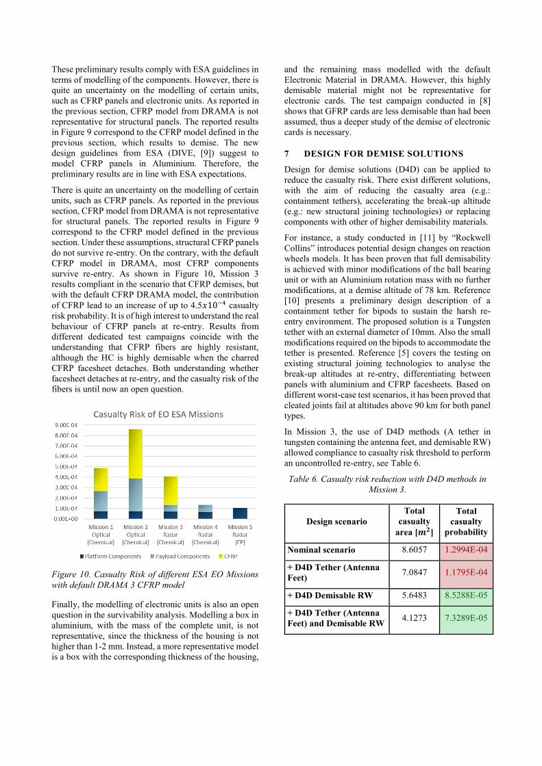
Dedicated test campaigns are found in literature.
Reference [6] shows that the Aluminium HC does not
demise until the CFRP fibers ablation. Even if the resin
first evaporates, the fibers act as thermal protection. On
the contrary, [7] demonstrates that when the resin starts
evaporating, the Aluminium inside increases temperature
and starts demising. The study conducted at OHB [5]
goes also in this direction, the CFRP facesheet detaches
from the honeycomb at low temperatures and the
honeycomb demises faster, see Figure 7. It is also
observed the matrix vaporizes at rather low temperatures,
leaving a char residue that acts as a matrix material for
the dry fibres. Where the char is burned away, fibres
become loose. The temperature at which the char leaves
the fibres could be seeked to model a CFRP model in
DRAMA as an equivalent metal, where the “melting
temperature” is the threshold value at which fibres are
released from the resin. Even if fibres survive re-entry,
the kinetic energy at impact of the separated fibres would
be sufficiently low to cause any injuries (e.g.: below the
15J threshold). Last, reference [8] concludes that the
integrity of CFRP facesheets is maintained after re-entry,
although these are very thin. Overall, results from these
different dedicated test campaigns coincide with the
understanding that CFRP fibers are highly resistant,
although the Honeycomb (HC) is highly demisable when
the charred CFRP facesheet detaches. Both
understanding whether facesheet detaches at re-entry,
and the casualty risk of the fibers is until now an open
question.
For comparison analysis of demising results with respect
to the CFRP DRAMA-based model, the CFRP model
from DEBRISK is used in OHB analysis. The equivalent
properties are given in Table 5.
Table 5. CFRP model based on DEBRISK [4]
Density [kg/m^3] 1600
Mean specific heat capacity (300 K - Tm)
[𝑱/𝒌𝒈𝑲] 879
Melting Temperature [K] 700
Specific heat of melting [J/kg] 233
Mean emission coefficient (300 K - Tm) [-] 0.999
CFRP sandwich panels are modelled with three separated
parts. CFRP facesheets are modelled as plates connected
to the Aluminium honeycomb. However, the recently
issued Guidelines for Analysing and Testing the Demise
of Man Made Space Objects During Re-entry (DIVE) [9]
suggest the modelling of the complete panel with
Aluminium-HC, including the mass of the CFRP
facesheets. It is highlighted the CFRP demise is an active
research topic, as shown with this reported literature
study. It then emphasizes the CFRP facesheets do not
necessarily form a separate critical element.
Leave footer empty – The Conference footer will be added to the first page of each paper.
Figure 7. Wind tunnel test results, Design for Demise
Breadboarding Study, OHB System AG [5].
6 UNCONTROLLED RE-ENTRY
SCENARIO
A Monte Carlo campaign is first conducted to determine
the break-up altitude of the main parent, at which it
releases all the included and connected components. The
break-up condition is based on a thermal criterion (by
default criterion in DRAMA 3.0.0); it occurs when the
parent primitive is completely demised. The worst case
scenario (mean-3𝜎 break-up altitude) is selected to
perform in a second step the survivability and casualty
risk analysis, forcing this value as the trigger for the
spacecraft fragmentation. In the example for Figure 8, the
resulting break-up altitude is 83km. The survivability and
casualty risk analysis for this mission was then performed
with the break-up condition forced at this predetermined
altitude.
In the break-up altitude analysis, a simplified model of
the satellite is employed. Variables of interest for the S/C
trajectory simulation and break-up of the main parent are
identified:
Spacecraft trajectory:
o Initial conditions;
o Total mass of the spacecraft;
o Cross-section area and drag
coefficient;
o Atmospheric model and density;
Break-up trigger:
o Mass, material and shape of the main
parent.
The simplified spacecraft model includes therefore the
external appendages that increase the cross-section area
(deployed solar arrays and payload housing) and dummy
masses to model the spacecraft with the mass at End of
Life (EOL); a dummy mass included as a child to the
main parent and a dummy mass included as a child to the
payload housing.
Figure 8. Break-up altitude results in the Monte Carlo
campaign for spacecraft simplified model. Break-up
condition is based on thermal criterion (Default criteria
in DRAMA).
Results from the survivability and casualty risk analysis
of different ESA Earth Observation missions, performed
during the Phases 0/B1, are gathered in Figure 9. Optical
missions result with a high casualty risk due the
numerous surviving components from the payload, made
in Silica, Titanium and Si3N4. Each optical unit is
attached with a bracket to the optical bench. Bipods can
even count as three components, with the two feet and
the bracket separated by the beam in a different material.
The number of surviving components is what highly
increases the casualty area, rather than their size. On the
contrary, the contribution of the payload to the casualty
risk budget in radar missions is on the same order that the
platform. The antenna feet in Titanium, as interface to the
platform, are the main contributors. Surviving platform
components are mainly the tank and the rotation mass of
reaction wheels. For electric propulsion systems, the
thrusters in Inconel and the Xenon flow controller in
Titanium survive due to the larger size and mass in
comparison with the regular chemical system.
Figure 9. Casualty risk of different ESA EO Missions
Leave footer empty – The Conference footer will be added to the first page of each paper.
These preliminary results comply with ESA guidelines in
terms of modelling of the components. However, there is
quite an uncertainty on the modelling of certain units,
such as CFRP panels and electronic units. As reported in
the previous section, CFRP model from DRAMA is not
representative for structural panels. The reported results
in Figure 9 correspond to the CFRP model defined in the
previous section, which results to demise. The new
design guidelines from ESA (DIVE, [9]) suggest to
model CFRP panels in Aluminium. Therefore, the
preliminary results are in line with ESA expectations.
There is quite an uncertainty on the modelling of certain
units, such as CFRP panels. As reported in the previous
section, CFRP model from DRAMA is not representative
for structural panels. The reported results in Figure 9
correspond to the CFRP model defined in the previous
section. Under these assumptions, structural CFRP panels
do not survive re-entry. On the contrary, with the default
CFRP model in DRAMA, most CFRP components
survive re-entry. As shown in Figure 10, Mission 3
results compliant in the scenario that CFRP demises, but
with the default CFRP DRAMA model, the contribution
of CFRP lead to an increase of up to 4.5𝑥10−4 casualty
risk probability. It is of high interest to understand the real
behaviour of CFRP panels at re-entry. Results from
different dedicated test campaigns coincide with the
understanding that CFRP fibers are highly resistant,
although the HC is highly demisable when the charred
CFRP facesheet detaches. Both understanding whether
facesheet detaches at re-entry, and the casualty risk of the
fibers is until now an open question.
Figure 10. Casualty Risk of different ESA EO Missions
with default DRAMA 3 CFRP model
Finally, the modelling of electronic units is also an open
question in the survivability analysis. Modelling a box in
aluminium, with the mass of the complete unit, is not
representative, since the thickness of the housing is not
higher than 1-2 mm. Instead, a more representative model
is a box with the corresponding thickness of the housing,
and the remaining mass modelled with the default
Electronic Material in DRAMA. However, this highly
demisable material might not be representative for
electronic cards. The test campaign conducted in [8]
shows that GFRP cards are less demisable than had been
assumed, thus a deeper study of the demise of electronic
cards is necessary.
7 DESIGN FOR DEMISE SOLUTIONS
Design for demise solutions (D4D) can be applied to
reduce the casualty risk. There exist different solutions,
with the aim of reducing the casualty area (e.g.:
containment tethers), accelerating the break-up altitude
(e.g.: new structural joining technologies) or replacing
components with other of higher demisability materials.
For instance, a study conducted in [11] by “Rockwell
Collins” introduces potential design changes on reaction
wheels models. It has been proven that full demisability
is achieved with minor modifications of the ball bearing
unit or with an Aluminium rotation mass with no further
modifications, at a demise altitude of 78 km. Reference
[10] presents a preliminary design description of a
containment tether for bipods to sustain the harsh re-
entry environment. The proposed solution is a Tungsten
tether with an external diameter of 10mm. Also the small
modifications required on the bipods to accommodate the
tether is presented. Reference [5] covers the testing on
existing structural joining technologies to analyse the
break-up altitudes at re-entry, differentiating between
panels with aluminium and CFRP facesheets. Based on
different worst-case test scenarios, it has been proved that
cleated joints fail at altitudes above 90 km for both panel
types.
In Mission 3, the use of D4D methods (A tether in
tungsten containing the antenna feet, and demisable RW)
allowed compliance to casualty risk threshold to perform
an uncontrolled re-entry, see Table 6.
Table 6. Casualty risk reduction with D4D methods in
Mission 3.
Design scenario
Total
casualty
area [𝒎𝟐]
Total
casualty
probability
Nominal scenario 8.6057 1.2994E-04
+ D4D Tether (Antenna
Feet) 7.0847 1.1795E-04
+ D4D Demisable RW 5.6483 8.5288E-05
+ D4D Tether (Antenna
Feet) and Demisable RW 4.1273 7.3289E-05
Leave footer empty – The Conference footer will be added to the first page of each paper.
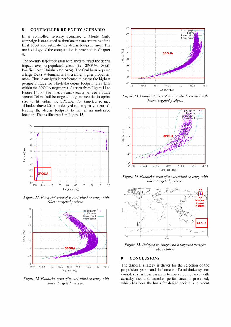
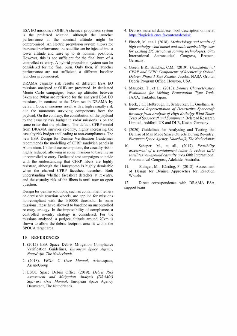
8 CONTROLLED RE-ENTRY SCENARIO
In a controlled re-entry scenario, a Monte Carlo
campaign is conducted to simulate the uncertainties of the
final boost and estimate the debris footprint area. The
methodology of the computation is provided in Chapter
4.
The re-entry trajectory shall be planed to target the debris
impact over unpopulated areas (i.e. SPOUA: South
Pacific Ocean Uninhabited Area). The final burn requires
a large Delta-V demand and therefore, higher propellant
mass. Thus, a analysis is performed to assess the highest
perigee altitude for which the debris footprint area falls
within the SPOUA target area. As seen from Figure 11 to
Figure 14, for the mission analysed, a perigee altitude
around 70km shall be targeted to guarantee the footprint
size to fit within the SPOUA. For targeted perigee
altitudes above 80km, a delayed re-entry may occurred,
leading the debris footprint to fall at an undesired
location. This is illustrated in Figure 15.
Figure 11. Footprint area of a controlled re-entry with
90km targeted perigee.
Figure 12. Footprint area of a controlled re-entry with
80km targeted perigee.
Figure 13. Footprint area of a controlled re-entry with
70km targeted perigee.
Figure 14. Footprint area of a controlled re-entry with
60km targeted perigee.
Figure 15. Delayed re-entry with a targeted perigee
above 80km
9 CONCLUSIONS
The disposal strategy is driver for the selection of the
propulsion system and the launcher. To minimize system
complexity, a flow diagram to assure compliance with
casualty risk and launcher performance is presented,
which has been the basis for design decisions in recent
Leave footer empty – The Conference footer will be added to the first page of each paper.
ESA EO missions at OHB. A chemical propulsion system
is the preferred solution, although the launcher
performance at the nominal altitude might be
compromised. An electric propulsion system allows for
increased performance, the satellite can be injected into a
lower altitude and raise up to its nominal positions.
However, this is not sufficient for the final burn of a
controlled re-entry. A hybrid propulsion system can be
considered for the final burn. Only then, if launcher
performance are not sufficient, a different baseline
launcher is considered.
DRAMA casualty risk results of different ESA EO
missions analysed at OHB are presented. In dedicated
Monte Carlo campaigns, break up altitudes between
84km and 90km are retrieved for the analysed ESA EO
missions, in contrast to the 78km set in DRAMA by
default. Optical missions result with a high casualty risk
due the numerous surviving components from the
payload. On the contrary, the contribution of the payload
to the casualty risk budget in radar missions is on the
same order that the platform. The default CFRP model
from DRAMA survives re-entry, highly increasing the
casualty risk budget and leading to non-compliances. The
new ESA Design for Demise Verification Guidelines
recommends the modelling of CFRP sandwich panels in
Aluminium. Under these assumptions, the casualty risk is
highly reduced, allowing in some missions to baseline an
uncontrolled re-entry. Dedicated test campaigns coincide
with the understanding that CFRP fibers are highly
resistant, although the Honeycomb is highly demisable
when the charred CFRP facesheet detaches. Both
understanding whether facesheet detaches at re-entry,
and the casualty risk of the fibers is until now an open
question.
Design for demise solutions, such as containment tethers
or demisable reaction wheels, are applied for missions
non-compliant with the 1/10000 threshold. In some
missions, these have allowed to baseline an uncontrolled
re-entry strategy. In the impossibility of compliance, a
controlled re-entry strategy is considered. For the
missions analysed, a perigee altitude around 70km is
shown to allow the debris footprint area fit within the
SPOUA target area.
10 REFERENCES
1. (2015) ESA Space Debris Mitigation Compliance
Verification Guidelines, European Space Agency,
Noordwijk, The Netherlands.
2. (2018). VEGA C User Manual, Arianespace,
ArianeGroup
3. ESOC Space Debris Office (2019). Debris Risk
Assessment and Mitigation Analysis (DRAMA)
Software User Manual, European Space Agency
Darmstadt, The Netherlands.
4. Debrisk material database. Tool description online at
https://logiciels.cnes.fr/content/debrisk.
5. Fittock, M. et all. (2018). Methodology and results of
high enthalpy wind tunnel and static demisability tests
for existing S/C structural joining technologies, 69th
International Astronautical Congress, Bremen,
Germany.
6. Green, B.R., Sanchez, C.M., (2019). Demisability of
GFRP and CFRP Components of Reentering Orbital
Debris: Phase I Test Results, Jacobs, NASA Orbital
Debris Program Office, Houston, USA.
7. Masuoka, T., et all. (2013). Demise Characteristics
Evaluation for Melting Promototion Type Tank,
JAXA, Tsukuba, Japan.
8. Beck, J.C., Holbrough, I., Schleutker, T., Guelhan, A.
Improved Representation of Destructive Spacecraft
Re-entry from Analysis of High Enthalpy Wind Tuner
Tests of Spacecraft and Equipment. Belstead Research
Limited, Ashford, UK and DLR, Koeln, Germany.
9. (2020) Guidelines for Analysing and Testing the
Demise of Man Made Space Objects During Re-entry,
European Space Agency, Noordwijk, The Netherlands
10. Scheper, M., et all., (2017). Feasibility
assessment of a containment tether to reduce LEO
satellites’ on-ground casualty area, 68th International
Astronautical Congress, Adelaide, Australia.
11. Ehinger, M., Kärräng, P., (2018). Assessment
of Design for Demise Approaches for Reaction
Wheels.
12. Direct correspondence with DRAMA ESA
support team


![Simon Pinnock ESA Technical Officer. GlobColour: Context and Motivation ESA Earth Observation Envelope Programme ESA EOEP-3 Declaration: Specific Objectives...[abridged]…](https://img.pdfslide.net/doc/110x75/551518e055034673228b4d4d/simon-pinnock-esa-technical-officer-globcolour-context-and-motivation-esa-earth-observation-envelope-programme-esa-eoep-3-declaration-specific-objectivesabridged.jpg)