Embed Size (px)
Citation preview

Analog Monitor Project User Manual
Page 1
EARTH PEOPLE TECHNOLOGY, Inc
ANALOG MONITOR PROJECT FOR THE ARDUINO UNO
User Manual
The Analog Monitor Project is designed for EPT USB CPLD Development System. It
samples all six of the analog inputs of the Arduino Uno and displays each of the values
on the PC in real time.
Circuit designs, software and documentation are copyright © 2012-2013, Earth People
Technology, Inc
Microsoft and Windows are both registered trademarks of Microsoft Corporation.
Altera is a trademark of the Altera Corporation. All other trademarks referenced herein
are the property of their respective owners and no trademark rights to the same are
claimed.

Analog Monitor Project User Manual
Page 2
Table of Contents 1 Analog Monitor Project Introduction ........................................................................ 4
1.1 Driver Installation ............................................................................................... 4 1.2 Software Installation ........................................................................................... 5
1.3 Active Host EndTerms ....................................................................................... 5 1.4 Active Transfer Library EndTerms .................................................................... 6
2 The Development Process ......................................................................................... 7 2.1 Designing a Simple Analog Monitor Project ..................................................... 8 2.2 Analog Monitor Project Equipment Needed ...................................................... 8 2.3 Analog Monitor Data Flow ................................................................................ 9
3 Arduino Analog Monitor Code ............................................................................... 11
Create Data Sampler ............................................................................................... 11
3.1 ................................................................................................................................ 11 3.1.1 Select I/O’s for Fast Throughput on Arduino ........................................... 11 3.1.2 Control Signals for the Analog Monitor ................................................... 13
3.2 Coding the Arduino Analog Monitor ............................................................... 15 3.3 Building Arduino Project ................................................................................. 20
3.4 Programming the Arduino ................................................................................ 23 4 CPLD Active Transfer EndTerms Coding .............................................................. 25
4.1 Define the User Design. ................................................................................... 25 4.2 Select the Input/Outputs ................................................................................... 27 4.3 Registers and Parameters .................................................................................. 29
4.4 Assignments ..................................................................................................... 32 4.5 Reset Circuit ..................................................................................................... 32
4.6 Input Registers .................................................................................................. 33 4.7 Start/Stop and Write Enable detection ............................................................. 34 4.8 EndTerm Selection ........................................................................................... 36
4.9 Upper/Lower Byte Selection ............................................................................ 38 4.10 Transfer Control Register State Machine ..................................................... 40 4.11 USB Transfer State Machine ........................................................................ 43 4.12 EndTerm Instantiation .................................................................................. 46
4.13 Compile/Synthesize the Project .................................................................... 50 4.14 Synthesizing .................................................................................................. 54 4.15 Program the CPLD........................................................................................ 57
5 PC: C# Project Design ............................................................................................ 61 5.1 Coding the C# Project ...................................................................................... 62
C# Project Creation .......................................................................................... 62 5.1.1 ......................................................................................................................... 62
5.1.2 C# Project Environment Setup .................................................................. 65 5.1.3 C# Object Initialization ............................................................................. 70 5.1.4 C# Project ListDevices .............................................................................. 70
5.1.5 C# Project Open Device ............................................................................ 72

Analog Monitor Project User Manual
Page 3
5.1.6 C# Project Callback Initialization ............................................................. 73
5.1.7 C# Project Controls ................................................................................... 74 5.1.8 C# Project Buttons .................................................................................... 75 5.1.9 C# Project EPTReadFunction Callback .................................................... 81 5.1.10 C# Project Scale Factor Selection ............................................................. 91 5.1.11 C# Project Completion .............................................................................. 95
5.2 PC: Compiling the Active Host Application .................................................... 95
6 Connecting the Project Together ............................................................................. 97
6.1 Testing the Project .......................................................................................... 100

Analog Monitor Project User Manual
Page 4
1 Analog Monitor Project Introduction The Analog Monitor Project uses the Earth People Technology USB-CPLD
development system hardware and the Arduino Uno connected to a Windows PC. The
project software uses the Microsoft C# Express in conjunction with the Active Host dll.
This User Manual will guide the user to create the Arduino code that will sample each
of the Analog inputs and transfer the digitally converted sample to the CPLD. The user
will be given instructions on creating the CPLD code that accepts each sample from the
Arduino and transmits it via USB to the PC. The manual completes with instruction of
how to create the C# application that will decode each sample and display on the screen
along with the other five analog input samples.
This is an advanced project and not for beginners to the Arduino family. However, it
does serve as an introduction to advanced programming techniques using Verilog for
programming the CPLD and C# for programming the user interface on the PC. The first
two sections provide a background for the PC and CPLD libraries.
1.1 Driver Installation Follow the instructions in the EPT USB CPLD Development System User Manual to
install all of the software and drivers for use with the hardware.

Analog Monitor Project User Manual
Page 5
If the driver has been installed correctly, you can go to the Device Manager and click on
the Universal Serial Bus controllers and see “USB Serial Converter A” and “USB Serial
Converter B”.
1.2 Software Installation Follow the the instructions in the EPT USB CPLD Development System User Manual
to install the following software:
Altera Quartus II
Microsoft C# Express
Arduino Wiring IDE
1.3 Active Host EndTerms The Active Host SDK is provided as a dll which easily interfaces to application
software written in C#, C++ or C. It runs on the PC and provides transparent connection
from PC application code through the USB driver to the user CPLD code. The user code
connects to “Endterms” in the Active Host dll. These Host “Endterms” have

Analog Monitor Project User Manual
Page 6
complementary HDL “Endterms” in the Active Transfer Library. Users have seamless
bi-directional communications at their disposal in the form of:
Trigger Endterm
Transfer Endterm
Block Endterm
User code writes to the Endterms as function calls. Just include the address of the
individual module (there are eight individually addressable modules of each Endterm).
Immediately after writing to the selected Endterm, the value is received at the HDL
Endterm in the CPLD.
Receiving data from the CPLD is made simple by Active Host. Active Host transfers
data from the CPLD as soon as it is available. It stores the transferred data into circular
buffer. When the transfer is complete, Active Host invokes a callback function which is
registered in the users application. This callback function provides a mechanism to
transparently receive data from the CPLD. The user application does not need to
schedule a read from the USB or call any blocking threads.
1.4 Active Transfer Library EndTerms The Active Transfer Library is a portfolio of HDL modules that provides an easy to use
yet powerful USB transfer mechanism. The user HDL code communicates with
EndTerms in the form of modules. These EndTerm modules are commensurate with the
Active Host EndTerms. There are three types of EndTerms in the Active Transfer
Library:
Trigger Endterm
Transfer Endterm
Block Endterm
They each have a simple interface that the user HDL code can use to send or receive
data across the USB. Writing to an EndTerm will cause the data to immediately arrive

Analog Monitor Project User Manual
Page 7
ACTIVE TRANSFER LIBRARY
TRIGGER ENDTERM
SINGLE TRANSFER ENDTERM
BLOCK ENDTERM
USER CODE
at the commensurate EndTerm in the Active Host/user application. The transfer through
the USB is transparent. User HDL code doesn’t need to set up Endpoints or respond to
Host initiated data requests. The whole process is easy yet powerful.
2 The Development Process The development of the Analog Monitor Project starts with the Arduino. The user will
write the code to sample each Analog input using the 10 bit ADC, then assert the write
enable which initiates the read cycle on the EPT-570-AP board. The user will write the
Verilog code for the CPLD which stores each sample from the Arduino board, then

Analog Monitor Project User Manual
Page 8
initiates the write cycle to PC. Finally, the user will write the C# code to accept each
byte from the EPT-570-AP board and assemble the bytes into the original 10 bit word
and display it in the requisite textbox in a Windows Form.
2.1 Designing a Simple Analog Monitor Project The Analog Monitor is an advanced project and not for beginners to the Arduino
family. However, it does serve as an introduction to advanced programming techniques
using Verilog for programming the CPLD and C# for programming the user interface
on the PC. The user should be familiar with the beginners projects for the Arduino Uno.
For an introduction to Verilog, go to:
www.asic-world.com/verilog/intro1.html#Introduction
For an introduction to C#, go to:
http://www.homeandlearn.co.uk/csharp/csharp.html
2.2 Analog Monitor Project Equipment Needed The equipment you will need for the Analog Monitor project is

Analog Monitor Project User Manual
Page 9
Earth People Technology EPT-570-AP-U2 board
Arduino Uno Board
PC running Windows 7 or equivalent, with 2 USB ports
USB cable Type B
USB cable Type Mini B
6 pin 2.54 mm Male Header
10 pin 2.54 mm Male Header
12 inches of 18 guage Wire
1 to 6 5VDC Power Supplies
Six 1 to 2 Foot Red Banana to Clip Leads
One 1 to 2 Foot Black Banana to Clip Lead
Five Six Inch Red Banana to Banana Lead
Five Six Inch Black Banana to Banana Lead
2.3 Analog Monitor Data Flow The data flow for the Analog Monitor project is shown below. The Arduino initializes
its ports and variables then enters the main loop() function. In the main loop, each
analog channel is converted into a 10 bit word. The digitized value is set on the PORT
B & D pins. Next, the EndTerm address is set and the Write Enable signal is asserted.
The next instruction de-asserts the Write Enable and the next analog channel goes
through the same process. At the end of the loop, all six channels have been digitized
and the data sent to the CPLD

Analog Monitor Project User Manual
Page 10
The CPLD does not need any initialization as the device is ready to operate soon after the power
is applied. The data flow in the EPT-570-AP starts with a wait loop for the Start_Stop_Control
signal to be asserted from the Control Register. Once this happens, the data flow will fall into the
wait loop for the Write Enable. When the Write Enable asserts, the State Machine leaves the
IDLE state and enters the START_TRANSFER state. In this state the EndTerm address will be
selected and the 10 bit digitized value is stored locally. The state machine will immediately
enter the FIRST_BYTE_EN state and initiate the lower byte (of the digitized value) transfer
across the USB. This state will wait for this first byte to be accepted by the Active Transfer
Library. Next, the FIRST_BYTE_RDY state is entered. In this state, the state machine will wait
for the Active Transfer Library to complete the transfer. Next, the upper byte of the digitized
value is transmitted across the USB in the same way as the lower byte in the
SECOND_BYTE_EN and SECOND_BYTE_RDY states. When the upper byte transfer is
complete, the state machine goes back into the IDLE state. The data flow waits in a loop for the
Write Enable to assert again and start the process again.
The C# data flow on the PC starts with the initialization of variables, controls, events, and read
callback functions. The Windows Form is displayed on the PC and the system registry is scanned
for any Earth People Technology devices. Any devices that are found are added to the drop down
box. The user must then select the available EPT device and click the Open control. This will
select the device and allocate all memory needed for the Active Host EndTerms. Next, the user
must click on the Start button. Clicking this button will send the control register value to the
EPT-570-AP board. This value is sent in a message. The CPLD Control Register State Machine
will decode this message and read the control register and assert the Start_Stop_Control signal.
Once this signal is asserted, the CPLD will send the lower byte and upper byte messages to the

Analog Monitor Project User Manual
Page 11
Active Host EndTerms. When bytes are received, the read callback function is called. The read
callback will call the EPTParseReceive() function which calls the TransferOutReceive()
function. In this function, the EndTerm address is selected and the upper byte is stored in the
upper portion of a local variable. The next time the TransferOutReceive() is called, from the read
callback, the EndTerm is selected and the lower byte is stored into the local variable. At this
point the full digitized value is transferred from the CPLD EndTerm and is ready for display.
The textbox is selected by the EndTerm address and is updated with the collected digitized value.
The cycle repeats until the Stop button is pressed.
3 Arduino Analog Monitor Code The first order of business is to layout the design. Start with the Arduino, and create a
simple analog signal sampler using the “analogRead()” function. Send the sampled
analog signal to the EPT-570_AP board using an address and an enable signal.
3.1 Select I/O’s for Fast Throughput on Arduino PORTD is an 8 bit port that is used to connect the lower 8 bits of the sample to the input
of the EPT-570-AP. Bits 8 and 9 of the sample are connected to bits 4 and 5 of PORTB.
The address for the EndTerms is three bits and occupies bits 1, 2 and 3 of PORTB.
There is also a one bit control line which will be used to inform the CPLD that a byte is
ready to be written to the USB. This is bit 0 of PORTB.
Arduino Uno
Connects
To
EPT-570-AP
Signal Port Pin Connector Connector Pin Port Signal
ADC
Bits 7 to 0
D 7 to 0 IOL J8 7 to 0 LB_IOL analog_monitor_
lower_byte
ADC Bit 9 B 5 IOH J10 4 LB_IOH analog_monitor_
upper_byte(1)
ADC Bit 8 B 4 IOH J10 1 LB_SER analog_monitor_
upper_byte(0)
EndTerm
Address Bit 2
B 3 IOH J10 3 LB_IOH analog_monitor_
address(2)
EndTerm B 2 IOH J10 2 LB_IOH analog_monitor_

Analog Monitor Project User Manual
Page 12
Address Bit 1 address(1)
EndTerm
Address Bit 0
B 1 IOH J10 1 LB_IOH analog_monitor_
address(0)
Write Enable B 0 IOH J10 0 LB_IOH analog_monitor_
en
Each port on the Arduino is controlled by three registers, which are also defined
variables in the Arduino language. The DDR register, determines whether the pin is an
INPUT or OUTPUT. The PORT register controls whether the pin is HIGH or LOW,
and the PIN register reads the state of INPUT pins set to input with pinMode(). The
maps of the ATmega328 chips show the ports.
DDR and PORT registers may be both written to, and read. PIN registers correspond to
the state of inputs and may only be read.
PORTD maps to Arduino digital pins 0 to 7
DDRD - The Port D Data Direction Register - read/write
PORTD - The Port D Data Register - read/write
PIND - The Port D Input Pins Register - read only
The ports and pins for the Analog Monitor Project project must be initialized in the
setup() function. The setup function will only run once, after each powerup or reset of
the Arduino board.
After the setup() function executes, the Arduino will enter the Loop() function and start
to perform the reading of the analog signals. And the PORTB bit 0 pin will be used to
latch the value on PORTD and PORTB pins into the CPLD.

Analog Monitor Project User Manual
Page 13
3.1 Create Data Sampler The analogRead() function is called to convert the analog signal on the given pin into a
10 bit digital word. The selections for the pin range from 0 to 5 for a total of six analog
inputs. These analog inputs are accessible from the AD connector on the UNO.
Calling the function analogRead(0) will convert the analog signal on the AD0 net into a
10 bit digital word. This word will be stored in a local variable in the Arduino code.
The next section will show the transmission of this value to the EPT-570-AP board.
Note that the ADC output can be selected to be either 8 bits or 10 bits. The ADLAR bit
in the ADMUX register will select if 10 bit or 8 bit precision is used. The ADC defaults
to 10 bit precision.
3.1.1 Control Signals for the Analog Monitor
The 10 bit digitized value from the analogRead() function is applied to the PORT B &
D pins. We will focus on keeping things fast on the Arduino. In order to do this, we will
use the port write function to transmit the sample to the EPT-570-AP.

Analog Monitor Project User Manual
Page 14
Using port writes is faster than using the built in functions in Arduino Processing. We
will use the port write to transfer the 10 bit ADC sample and use it to set the address for
the Active Transfer Library EndTerm and for the write enable.
Here, notice that the PORTD is set to the value of AdcValue. This will naturally set the
the bottom 8 bits of AdcValue to PORTD. To set the bits 8 and 9 of AdcValue to
PORTB bits 4 and 5, we use a left shift of four bits. The left shift operator >> will shift
everything in AdcValue to the left by four bits. We only want bits 8 and 9, so we mask
off everything but bits 8 and 9, (AdcValue & 0x0300). Then apply the shift.
The Analog Monitor must assert an EndTerm Address and the Write Enable to cause
the EPT-570-AP to process the digitized value.
We will do this by first setting the address and the upper 2 bits of the digitized value on
the output pins of PORTB. Then set Write Enable high. Finally, set Write Enable low.
The signal timing shows the ADC Conversion Start for each ADC channel followed by
setting the control signals.

Analog Monitor Project User Manual
Page 15
Each time the Write Enable asserts and de-asserts, the cycle repeats with the next
analogRead().
This continues for all six channels. The end of the loop() is reached, and the process
starts all over again.
3.2 Coding the Arduino Analog Monitor Now that we have the Analog Monitor ports, analog read, address selection and write
enable defined , we can add all six channels in the loop() function and complete the
Analog Monitor. The first instruction in the loop() is a delay. This delay is useful
because the display to screen on the C# side takes several milliseconds. Because we are
using a high speed USB, the Arduino takes only a few instructions to write to the EPT-
570-AP. It will easily over fill the memory buffers in the C#. So, some delay is
necessary.
The next instructions are to read the analogRead(0) function using channel 0 and store
the value in the integer, AdcValue. The analogRead() function defaults to 10 bits. For
the Arduino, we want to transmit the AdcValue in the fewest instructions possible. So,

Analog Monitor Project User Manual
Page 16
we will add the bottom byte of AdcValue to PORTD and the top two bits to pins 4 and
5 of PORTB. To do this, we have to shift bits 8 and 9 of AdcValue to bit 4 and 5 of
PORTB. The code requires the right shift by 4.
With PORTD set to the lower byte of AdcValue and the upper two bits shifted into
position, we will set PORTB to the address of the channel to transmit along with the
upper bits. At this point we will keep Write Enable low.
In the next instruction, we set the Write Enable high. Immediately following this
instruction, we set the Write Enable low. This will cause the entire 10 bit AdcValue to
transmit in the fewest instructions. The CPLD is clocked at 66 MHz which allows it to
transmit two bytes over the USB in less time than the Arduino. So, we let the CPLD do
the heavy lifting.
The Analog Monitor code will continue with samling the next channel and transmitting
its digitized value to the CPLD. Each iteration of the loop() function, samples all six
Uno analog channels and transmits them to the CPLD. The delay of 10 milliseconds
pauses the program each iteration.

Analog Monitor Project User Manual
Page 17
So, the code looks like this:

Analog Monitor Project User Manual
Page 18

Analog Monitor Project User Manual
Page 19

Analog Monitor Project User Manual
Page 20
The Arduino code runs open loop. This means that the C# code and the CPLD cannot
control or delay it. As soon as the code is loaded from flash, it initializes local variables,
ports, and registers and starts running the instructions in the loop() function. The loop
will continue to sample analog channels and transmit them to the EPT-570-AP until the
power is removed.
3.3 Building Arduino Project Building the Arduino project is the process of converting (compiling) the code you just
wrote into machine level code that the processor can understand. The Arduino IDE is
the software tool that does the compiling. The machine level code is a set of basic
instructions that the processor uses to perform the functions the user code. Browse to
the \Projects_Arduino\Arduino_Analog_Monitor\ Arduino_Analog_Monitor_Code_U2\
folder of the UNO_ANALOG_MONITOR_PROJECT_CD. Locate the Arduino_
Analog_Monitor_Code_U2.ino file.
To compile your code,
Open up the Arduino IDE

Analog Monitor Project User Manual
Page 21
Load your code into the Sketch.

Analog Monitor Project User Manual
Page 22
Click the Verify button

Analog Monitor Project User Manual
Page 23
The sketch will compile
If there are no errors, the compiling will complete successfully
Now we are done with compiling and ready to program the Arduino
3.4 Programming the Arduino Programming the Arduino is the process of downloading the user’s compiled code into
the Flash memory of the Atmel ATMega328 chip. Once the code is downloaded, the
Arduino IDE resets the chip and the processor starts executing out of Flash memory.
To program the Arduino
Connect the USB cable from PC to Arduino

Analog Monitor Project User Manual
Page 24
Plug in your board and wait for Windows complete the driver installation
process.
Next, click on Tools and select Serial Port, then click the available port.
To load the code, click on the Upload button.

Analog Monitor Project User Manual
Page 25
When the code has completed loading, the Arduino IDE will automatically command
the processor to start executing the code. The Arduino is now ready for the EPT-570-
AP.
4 CPLD Active Transfer EndTerms Coding The EPT-570-AP will accept the digitized data sampled by the Arduino and transfer it
to the PC. It is designed to plug directly into the Arduino Uno and there is no need for
external wires to be added. The Active Transfer Library is used to send the data to the
PC. The Active Transfer EndTerms are used to connect the Active Transfer Library to
the user code. This makes it easy to transfer data to and from the PC via the USB. The
user needs to create a state machine to control the transfer between the incoming data
and the Active Transfer EndTerms.
4.1 Define the User Design. In this step we will define the user’s code and include EndTerms and the EPT Active
Transfer Library. The Active Transfer Library contains a set of files with a “.vqm”
name extension which select particular operations to perform (e.g., byte transfer, block
transfer, trigger).. The active_transfer_library.vqm file must be included in the top level
file of the project. The EndTerms will connect to the active_transfer_library and
provide a path to connect user code to the library. All of these files are available on the
Earth People Technology Project CD.

Analog Monitor Project User Manual
Page 26
ACTIVE TRANSFER LIBRARY
TRIGGER ENDTERM
SINGLE TRANSFER ENDTERM
BLOCK ENDTERM
USER CODE
We will build our CPLD project using Quartus II software from Altera. The primary file
defining the user’s CPLD project is named “EPT_570_AP_U2_Top.v”. It defines the
user code and connects the active_transfer_library and Endterms.
The Analog Monitor project needs to accept a 10 bit value that spans the J8 connector
and the J10 connector. Three bits select the Transfer EndTerm to transmit on and a
write enable bit is used to start a state machine which latches all values and transmits
the digitized value. Because the active_transfer_library runs at 66 MHz we will need to
add some code ensure that the slower Write Enable signal from the Arduino can latch
the data into the Transfer EndTerm.

Analog Monitor Project User Manual
Page 27
The first thing to do is to create a top level file for the project. The top level file will
include the input and outputs for the CPLD. These are declared according to the Verilog
syntax rules. We won’t go through all the rules of Verilog here, but feel free to explore
the language more thoroughly at:
www.asic-world.com/verilog/intro1.html#Introduction
4.2 Select the Input/Outputs We need to set the inputs and outputs for EPT_570_AP_U2_Top.v. The I/O nets will
stay the same for all EPT projects. All of the usable pins are connected to traces on the
EPT-570-AP board and serve specific functions. However, the pins that connect to the
Arduino can be set to either inputs or outputs. It is in the port section of the Verilog
module that the Arduino pins can be set. For the Analog Monitor project, we will read
from the J8 and J10 connectors. So, we set these as inputs. Since the analog inputs to
the Arduino are on the J9 connector, we will set it up as inputs. The following nets are
used to connect to the EPT-570-AP connectors.
Arduino Uno
Connects
To
EPT-570-AP
Signal Port Pin Connector Connector Pin Port Signal
ADC
Bits 7 to 0
D 7 to 0 IOL J8 7 to 0 LB_IOL analog_monitor_
lower_byte
ADC Bit 9 B 5 IOH J10 4 LB_IOH analog_monitor_
upper_byte(1)
ADC Bit 8 B 4 IOH J10 1 LB_SER analog_monitor_
upper_byte(0)
EndTerm
Address Bit 2
B 3 IOH J10 3 LB_IOH analog_monitor_
address(2)
EndTerm
Address Bit 1
B 2 IOH J10 2 LB_IOH analog_monitor_
address(1)
EndTerm
Address Bit 0
B 1 IOH J10 1 LB_IOH analog_monitor_
address(0)
Write Enable B 0 IOH J10 0 LB_IOH analog_monitor_
en
Each net is followed by the net type wire or reg. If it is a vector, the array description
must be added.

Analog Monitor Project User Manual
Page 28

Analog Monitor Project User Manual
Page 29
4.3 Registers and Parameters Next, the parameter’s are defined. These are used as constants in the user code.

Analog Monitor Project User Manual
Page 30
Next is the Internal Signal and Register Declarations.

Analog Monitor Project User Manual
Page 31

Analog Monitor Project User Manual
Page 32
4.4 Assignments Next, add the assignments. These assignments will set the direction of the bus
transceivers that interface to the Arduino I/O’s. The transceivers also include an output
enable bit.
4.5 Reset Circuit The reset signal is generated by a counter that starts counting upon power up. When the
counter reaches GLOBAL_RESET_COUNT.

Analog Monitor Project User Manual
Page 33
4.6 Input Registers The section labled “Register the Inputs” applies the inputs from the Arduino to clocked
registers. This will eliminate any noise on these inputs from propagating through to the
state machines of the CPLD.

Analog Monitor Project User Manual
Page 34
4.7 Start/Stop and Write Enable detection Next, we will add the transfer detection signal from the Arduino. This block will sample
the Write Enable signal and wait for it to go high.
It is also used to provide start/stop control for the CPLD code. This block will use four
registers to control the data and starting the state machine.
transfer_write_reg –This is a latch register to hold the state of the Write Enable.
transfer_write –This register is used to start the state machine and initiate the
multi byte write to the PC.
transfer_write_data –This is a 10 bit register to hold the value of the analog
sample from the Arduino.
transfer_address – 8 bit register to hold the EndTerm address from the Arduino.
The start_stop_cntrl signal is monitored every clock cycle. If it is sampled high, the
output enables of the 74LVC4245 transceivers are set low and the outputs become

Analog Monitor Project User Manual
Page 35
active. When start_stop_cntrl goes low, the output enables of the 74LVC4245
transceivers are set high and sets the outputs to inactive.
This block will compare the input signal on analog_monitor_en to a high. The
analog_monitor_en is the registered version of LB_IOH[0]. When bit goes high, the
priority encoder goes into statement 1 and sets transfer_write_reg and transfer_write
high and latches the value on the analog_monitor_upper_byte and
analog_monitor_lower_byte to the transfer_write_data register. The
analog_monitor_address will be set to transfer_address. By setting transfer_write_reg
high, the priority encoder goes into statement 2 which will set transfer_write register to
low and stay in statement 2 of the priority encoder. When the analog_monitor_en
signal goes low, the encoder will reset transfer_write_reg and transfer_write to low. The
encoder goes back to waiting for the analog_monitor_en to assert high.

Analog Monitor Project User Manual
Page 36
4.8 EndTerm Selection The Analog Monitor Project includes the use of six Active Transfer EndTerms. Each
EndTerm must have an address.
When the user code is ready to transmit a byte to the EndTerm, he must assert the
start_transfer port of the module. Each of Active_Transfer EndTerms has its own
dedicated net to pass to the start_transfer port. These nets are:

Analog Monitor Project User Manual
Page 37
This s a vector register with a range of 5 to 0. So, six individual signals can be asserted
to start the transfer to any of six Active_Transfer EndTerms. These nets are exclusively
selected by using the address passed from the Arduino. This selection is performed
using a case statement. We use an intermediate register vector to capture the address,
then later apply the storage vector results to the start_transfer_array. The
transfer_address vector is stored in the Transfer Detection block above. The EndTerm
selection is only performed when the USB Transfer state machine is in the
START_TRANSFER state.

Analog Monitor Project User Manual
Page 38
4.9 Upper/Lower Byte Selection The “Transfer Upper/Lower byte using selected Active Transfer EndTerm” block
selects the appropriate byte from the stored digitized sample and asserts the
start_transfer_array index. The EndTerm address was selected in the “Select the
Transfer EndTerm…” block.
This block will require three registers:
first_byte_complete – used to indicate to the USB Transfer state machine that
the upper byte has been transferred to the Active Transfer EndTerm.
second_byte_complete– used to indicate to the USB Transfer state machine that
the lower byte has been transferred to the Active Transfer EndTerm.
start_transfer_array – this is a six bit vector used to accept the address of the
EndTerm selected in the “Select the Transfer EndTerm…” block (transfer_out).

Analog Monitor Project User Manual
Page 39
The block is a conditional branch statement that uses the following states from the USB
Transfer state machine to branch:
1. After analog_monitor_en is asserted, the state machine will reach
state[FIRST_BYTE_EN]. In this state the signal, first_byte_complete, will go
high and the start_transfer_array is set to the EndTerm selected in the “Select
the Transfer EndTerm…” block. This is the transfer_out vector.
Each bit of start_transfer_array will coorespnd to exactly one EndTerm and keep
the rest de-asserted. In this conditional branch the selected EndTerm will
transfer the lower byte on its transfer_to_host port. The second_byte_complete
signal is used as a conditional branch to leave state[SECOND_BYTE_EN] and
enter state[SECOND_BYTE_RDY]. Byte selection is performed using an assign
statement to the transfer_out_byte:
2. EndTerm selection of transfer_out. The start_transfer_array allows only one bit
to be high at one time. This will allow only one EndTerm to transfer the upper
byte on its transfer_to_host port. The first_byte_complete signal is used as a
conditional branch to leave state[FIRST_BYTE_EN] and enter
state[FIRST_BYTE_RDY] in the USB Transfer state machine.
3. The next conditional branch is reached when first_byte_complete goes high and
state[FIRST_BYTE_EN] is high. In this state, the start_transfer_array is set to
zero.
4. The third conditional branch is reached when state[FIRST_BYTE_EN] is low
and signals that the upper byte transfer is complete and the state machine has
moved to another state.

Analog Monitor Project User Manual
Page 40
5. The next conditional branch is reach when second_byte_complete is low and
state[SECOND_BYTE_EN] is high. In this state the signal
second_byte_complete will go high and the start_transfer_array will transfer the
lower byte on its transfer_to_host port. The second_byte_complete signal is
used as a conditional branch to leave state[SECOND_BYTE_EN] and enter
state[SECOND_BYTE_RDY].
6. The next conditional branch is reached when second_byte_complete goes high
and state[SECOND_BYTE_EN] is high. In this state, the start_transfer_array is
set to zero.
7. The third conditional branch is reached when state[SECOND_BYTE_EN] is
low and signals that the upper byte transfer is complete and the state machine
has moved to another state.
4.10 Transfer Control Register State Machine The start_stop_cntrl signal is set by using the TRANSFER_CONTROL state machine
in the following section. So, if the start_stop_cntrl signal is set, the CPLD code will
enter the conditional branch code and wait for the Write Enable signal to assert.
Next, we add the TRANSFER_CONTROL state machine to read the Control Register
from the Host PC using the active_transfer EndTerm. This state machine will decode
the 8 bit control register only after a sequence of three 8 bit bytes in the order of 0x5a,
0xc3, 0x7e. The operation of the state machine is as follows.
1. The TRANSFER_CONTROL state machine will stay in the idle state of the
parallel encoder until a byte from the active_transfer transfer_to_device register
receives a 0x5a.
2. This will cause the transfer_control_state to be changed to
TRANSFER_CONTROL_HDR1.
3. The state machine will stay in the TRANSFER_CONTROL_HDR1 state until
the next byte is read from the active_transfer.
4. If the byte from transfer_to_device is a 0xc3, the transfer_control_state will be
changed to TRANSFER_CONTROL_HDR2.
5. If the byte from transfer_to_device is not a 0xc3, the transfer_control_state will
go back to idle.

Analog Monitor Project User Manual
Page 41
6. In the TRANSFER_CONTROL_HDR2 state , the state machine will stay in this
state until the next byte from the active_transfer is received.
7. If the byte from transfer_to_device is a 0x7e, the transfer_control_state will be
changed to TRANSFER_DECODE_BYTE.
8. If the byte from transfer_to_device is not a 0x7e, the transfer_control_state will
go back to idle.
9. In the TRANSFER_DECODE_BYTE state , the state machine will stay in this
state until the next byte from the active_transfer.
10. The next byte transferred from active_transfer will be decoded as the Control
Register.
The bits of the Control Register are defined below.
Register Bits Description Assertion
Control 0 Start Stop Cntrl High
1 Not Used
2 LED Reset High
3 Switch Reset High
4 Transfer In Loop Back High
5 Not Used
6 Not Used
7 Not Used
7 Not Used

Analog Monitor Project User Manual
Page 42

Analog Monitor Project User Manual
Page 43
4.11 USB Transfer State Machine The USB Transfer State Machine is quite a bit different than the Transfer Control state
machine. It is two always statement one-hot finite state machine. It is used here because
it provides high speed glitch free operation. One hot means that it has one register for
each state. The two always block setup allows a synchronous operation to be relegated
to moving the state machine to the next state.

Analog Monitor Project User Manual
Page 44
An asynchronous always block is used to select which state will be the next state. All of
the outputs are handled in their own always blocks and separate from the state machine.
This asynchronous always block is the one which causes the state machines conditional
branches to update. If the conditional branches are not updated with the correct inputs,
then the next[…] statement will not get updated with the correct state and the state
machine could get stuck in the wrong state. So, each input into the state machine MUST
be entered into the sensitivity list of the “State Defiinitions” always block.
1. The state machine stays in state[IDLE] until the analog_monitor_en goes high.
When this signal goes high, the state machine goes into

Analog Monitor Project User Manual
Page 45
state[START_TRANSFER]. This state causes the transfer_out to latch an
EndTerm selection based on the transfer_address. This state does not have a
conditional branch, so it immediately proceeds to state[FIRST_BYTE_EN].
2. In state[FIRST_BYTE_EN], the “Transfer Upper/Lower byte using selected
Active Transfer EndTerm” block will select the upper byte to transfer over the
USB. A conditional branch causes the state machine to stay in this state until
first_byte_complete goes high.
3. The next state is state[FIRST_BYTE_RDY]. Here the byte has been transferred
into the Active Transfer EndTerm selected by start_transfer_array. This state has
a conditional branch that waits until the byte has been transferred across the
USB and the Active Transfer Library is ready. It waits for transfer_busy_array
to be zero.
4. The state machine progresses to state[SECOND_BYTE_EN] and causes the
“Transfer Upper/Lower byte using selected Active Transfer EndTerm” block to
select the lower byte to transfer over the USB. A conditional branch causes the
state machine to stay in this state until second_byte_complete goes high. Upon
its assertion, the state machine proceeds to state[SECOND_BYTE_RDY].
5. In state[SECOND_BYTE_RDY] the byte has been transferred into the Active
Transfer EndTerm selected by start_transfer_array. This state has a conditional
branch that waits until the byte has been transferred across the USB and the
Active Transfer Library is ready. It waits for transfer_busy_array to be zero.
6. Upon successful completion of the second byte transfer, the state machine goes
back to the state[IDLE] and waits for analog_monitor_en to go high and start the
process over again.

Analog Monitor Project User Manual
Page 46
4.12 EndTerm Instantiation Next, up is the instantiation for the active_transfer_library. The ports include the input
and output pins and the two buses that connect the active modules. These buses are the
input UC_IN[23:0] and output UC_OUT[21:0].

Analog Monitor Project User Manual
Page 47
Finally, we instantiate the EndTerms. For the Analog Monitor project, we only need
active_transfer and active_trigger EndTerms. The uc_out port for both modules must be
shared. Since they both drive this bus, a bus wide wired-or circuit is used so that they
don’t drive each other. The active_transfer EndTerm has a port for the address
(uc_addr). This allows the PC to address up to 8 different modules. Just add a three bit
address to this port and the PC must add this same address to communicate with this
module.
Next, we will instantiate six Active Transfer EndTerms. So, add the leaf instantiation
with the address fixed 1, 2, 3, 4, 5, 6, for each EndTerm. Add the start_transfer_array,

Analog Monitor Project User Manual
Page 48
transfer_busy_array and transf_out_byte to control the transmission of the digitized
value across the USB.

Analog Monitor Project User Manual
Page 49

Analog Monitor Project User Manual
Page 50
The “endmodule” signifies the module is done and no more code is allowed beyond that
point.
Next, we are ready to compile and synthesize.
4.13 Compile/Synthesize the Project The Quartus II application will compile/ synthesize the user code,
active_transfer_library, and the Active EndTerms. The result of this step is a file
containing the CPLD code with “*.pof”. First, we need to create a project in the
Quartus II environment. Follow the directions in the section: “Compiling, Synthesizing,
and Programming CPLD” of the User Manual.

Analog Monitor Project User Manual
Page 51
Bring up Quartus II, then use Windows Explorer to browse to
c:/altera/xxx/quartus/qdesigns create a new directory called: “EPT_Analog_Monitor”.
Open Quartus II by clicking on the icon .
Under Quartus, Select File->New Project Wizard. The Wizard will walk you through
setting up files and directories for your project.

Analog Monitor Project User Manual
Page 52

Analog Monitor Project User Manual
Page 53
At the Top-Level Entity page, browse to the
c:\altera\xxx\quartus\qdesigns\EPT_Analog_Monitor directory to store your project.
Type in a name for your project “EPT_570_AP_U2_Top”.
Follow the steps up to Add Files. At the Add Files box, click on the Browse button and
navigate to the project Analog Monitor install folder in the dialog box. Browse to the
\Projects_HDL\EPT_ Analog_Monitor \EPT_570_AP_U2_Top folder of the EPT USB-
CPLD Development System CD. Copy the files from the \src directory.
Active_transfer.vqm
Active_trigger.vqm
Active_transfer_library.vqm
eptWireOr.v
ETP_570_AP_U2_Top.v
Add the files:
Select Next, at the Device Family group, select MAX II for Family. In the Available
Devices group, browse down to EPM570T100C5 for Name.

Analog Monitor Project User Manual
Page 54
Select Next, leave defaults for the EDA Tool Settings.
Select Next, then select Finish. You are done with the project level selections.
4.14 Synthesizing With the project created, we need to assign pins to the project. The signals defined in
the top level file (in this case: EPT_570_AP_U2_Top.v) will connect directly to pins on
the CPLD. The Pin Planner Tool from Quartus II will add the pins and check to verify
that our pin selections do not violate any restrictions of the device. In the case of this
example we will import pin assignments that created at an earlier time. Under
Assignments, Select Import Assignments.
At the Import Assignment dialog box, Browse to the
\Projects_HDL\EPT_Transfer_Test \Altera_EPM570_U2 folder of the EPT
ANALOG_MONITOR_PROJECT CD. Select the “EPT_570_AP_U2_Top.qsf” file.

Analog Monitor Project User Manual
Page 55
Next, we need to add the Synopsys Design Constraint file. This file contains timing
constraints which forces the built in tool called TimeQuest Timing Analyzer to analyze
the path of the synthesized HDL code with setup and hold times of the internal registers.
It takes note of any path that may be too long to appropriately meet the timing
qualifications. For more information on TimeQuest Timing Analyzer, see
http://www.altera.com/literature/hb/qts/qts_qii53018.pdf?GSA_pos=1&WT.oss_r=1&
WT.oss=TimeQuest Timing Analyzer
Browse to the \Projects_HDL\EPT_ Analog_Monitor \Altera_EPM570_U2 folder of the
EPT USB-CPLD Development System CD. Select the “EPT_570_AP_U2_Top.sdc”
file.
Copy the file and browse to c:\altera\xxx\quartus\qdesigns\EPT_Analog_Monitor
directory. Paste the file.

Analog Monitor Project User Manual
Page 56
and select the Start Compilation button.
This will cause the compile and synthesization process. After successful completion, the
screen should look like the following:

Analog Monitor Project User Manual
Page 57
If the synthesis fails, you will see the failure message in the message window. Note that
in addition to fatal errors, the compile process can produce “warnings” which do not
necessarily prevent execution of the code but which should be corrected eventually.
At this point the project has been successfully compiled, synthesized and a
programming file has been produced. See the next section on how to program the
CPLD.
4.15 Program the CPLD The final step is programming the “*.pof” file into the CPLD.
Connect the EPT-570-AP to the PC,
Open up Quartus II,
Open the programmer tool
If the project created in the previous sections is not open, open it. Click on the
Programmer button.

Analog Monitor Project User Manual
Page 58
The Programmer Window will open up with the programming file selected. Click on the
Hardware Setup button in the upper left corner.
The Hardware Setup Window will open. In the “Available hardware items”, double
click on “EPT-Blaster v1.3b”.

Analog Monitor Project User Manual
Page 59
If you successfully double clicked, the “Currently selected hardware:” dropdown box
will show the “EPT-Blaster v1.3b”.
Click the “Close” button.
Next, selet the checkbox under the “Program/Configure” of the Programmer Tool. The
checkboxes for the CFM and UFM will be selected automatically.

Analog Monitor Project User Manual
Page 60
Click on the Start button to to start programming the CPLD. The Progress bar will
indicate the progress of programming.
When the programming is complete, the Progress bar will indicate success.

Analog Monitor Project User Manual
Page 61
At this point, the EPT-570-AP is programmed and ready for use.
5 PC: C# Project Design The final piece of the Analog Monitor Project is the PC application. This application
will fetch the data from the CPLD of the EPT-570-AP and display it on the screen. It
includes user code, windows form, and the Active_Host DLL.
The Active_Host DLL is designed to transfer data from the CPLD when it becomes
available. The data will be stored into local memory of the PC, and an event will be
triggered to inform the user code that data is available from the addressed module of the
CPLD. This method, from the user code on the PC, makes the data transfer transparent.
The data just appears in memory and the user code will direct the data to a textbox on
the Windows Form.
The Analog Monitor project will perform the following functions.
Find EPT-570-AP Device.
Open EPT-570-AP Device.
Start the Arduino data collection process.
Wait for data from EPT-570-AP.
Decode byte position, upper or lower.
Display data from EPT-570-AP in textbox.

Analog Monitor Project User Manual
Page 62
5.1 Coding the C# Project The user code is based on the .NET Framework and written in C#. The language is great
for beginners as it is a subset of the C++ language. It has the look and feel of the
familiar C language but adds the ease of use of classes, inheritance and method
overloading. C# is an event based language which changes the method of writing code
for this project. You will need to get some background knowledge in coding with C#
and the .NET Framework on the PC. For a better description of event based language
programming and C#, see the following for a turtorial
http://www.homeandlearn.co.uk/csharp/csharp.html
5.1.1 C# Project Creation
To start the project, use the wizard to create project called “EPT_Analog_Monitor”.
When the wizard completes, the C# Express main window will look like the following.

Analog Monitor Project User Manual
Page 63
The setup statements create the namespace and the class for the project. There are
several other files that are created by the wizard such as Form1.Designer.cs,
Program.cs, Form1.resx. We don’t need to go into these support files, we will just focus
on the Form1.cs as this is where all the user code goes.
Click on File->Save Project as. Browse to C:\Users\<user name>\Documents\Visual
Studio 2010\Projects, and click Select Folder. Click the Save button.
Locate the \Projects_ActiveHost_64Bit\EPT_Analog_Monitor\ folder in the
UNO_ANALOG_MONITOR_PROJECT_CD. Copy the following files:
active_transfer_x64.cs
Form1.cs

Analog Monitor Project User Manual
Page 64
Form1.Designer.cs
Form1.resx
Program.cs
ScaleFactorMenu.cs
Open a Windows Explorer window and browse to
C:\Users\NelsonsTrfgr\Documents\Visual Studio 2010 \Projects \EPT_Analog_Monitor
\EPT_Analog_Monitor. Paste the files to this folder.
In the Solution Explorer Window, right click on the project name,
EPT_Analog_Monitor and select Add->Existing Item
Select the following files:
active_transfer_x64.cs
ScaleFactorMenu.cs

Analog Monitor Project User Manual
Page 65
Click Add.
5.1.2 C# Project Environment Setup
The project environment must be set up correctly in order to produce an application that
runs correctly on the target platform. Visual C# Express defaults new projects to 32 bits.
If your OS is a 64 bit platform, use the following directions to set up a 64 bit project.
First, we need tell C# Express to produce 64 bit code if we are running on a x64
platform. Go to Tools->Settings and select Expert Settings
Go to Tools->Options, locate the “Show all settings” check box. Check the box.

Analog Monitor Project User Manual
Page 66
In the window on the left, go to “Projects and Solutions”. Locate the “Show advanced
build configurations” check box. Check the box.
Go to Build->Configuration Manager.

Analog Monitor Project User Manual
Page 67
In the Configuration Manager window, locate the “Active solution platform:” label,
select “New” from the drop down box.
In the New Solution Platform window, click on the drop down box under “Type or
select the new platform:” and select “x64”.

Analog Monitor Project User Manual
Page 68
Click the Ok button. Verify that the “Active Solution Platform” and the “Platform” tab
are both showing “x64”.
Click Close.
Then, using the Solution Explorer, you can right click on the project, select Properties
and click on the Build tab on the right of the properties window.

Analog Monitor Project User Manual
Page 69
Verify that the “Platform:” label has “Active (x64)” selected from the drop down box.
Next, unsafe code needs to be allowed so that C# can be passed pointer values from the
Active Host.
Locate the “Allow unsafe code” check box. Check the box

Analog Monitor Project User Manual
Page 70
5.1.3 C# Object Initialization
Now we are ready to start coding.
Next, we add two classes for our device. One class stores the information useful for our
device for Transmit to the EndTerms such as, address of module, length of transfer etc.
The next class is used to store parameters for receiving data from the device.
The first function called when the Windows Form loads up is the EPT_Analog_Monitor
_Load(). This function is called automatically upon the completion of the Windows
Form, so there is no need to do anything to call it. Once this function is called, it in turn
calls the ListDevices().
5.1.4 C# Project ListDevices
The ListDevices() function calls the EPT_AH_Open() function to load up the

Analog Monitor Project User Manual
Page 71
ActiveHost Dll. Next, it calls EPT_AH_QueryDevices() which searches through the
registry files to determine the number of EPT devices attached to the PC. Next,
EPT_AH_GetDeviceName() is called inside a for loop to return the ASCII name of
each device attached to the PC. It will automatically populate the combo box,
cmbDevList with all the EPT devices it finds.

Analog Monitor Project User Manual
Page 72
5.1.5 C# Project Open Device
The user will select the device from the drop down combo box. This value can be sent
to the OpenDevice() function using the button Click of the Open button.
The device_index variable is used to store the index of the device selected from the
combo box. This variable is passed into the EPT_AH_OpenDeviceByIndex(). This
process is started by the user clicking on the “Open” button. If the function is
successful, the device name is displayed in the label, labelDeviceCnt. Next, the device
is made the active device and the call back function is registered using the
RegisterCallBack() function. Finally, the Open button is grayed out and the Close
button is made active.

Analog Monitor Project User Manual
Page 73
5.1.6 C# Project Callback Initialization
Next, the callback function is populated. This function will be called from the Active
Host dll. When the EPT Device has transferred data to the PC, the callback function
will do something with the data and command.

Analog Monitor Project User Manual
Page 74
Because the callback function communicates directly with the dll and must pass
pointers from the dll to the C#, marshaling must be used. Marshaling is an advanced C#
topic and will not be covered in this manual. We will let the callback function work in
the background and we only need to use the EPTParseReceive() function to handle
incoming data.
5.1.7 C# Project Controls
Controls such as buttons are added to the Form1.cs[Design] window which allow
turning on and off signals. These include
btnOk
btnCancel
btnOpenDevice
btnCloseDevice
btnStart
btnStop
btnSetScaleFactor
btnResetBlock1 .. 6
Textboxes are used to display information on the Windows form. These textboxes are:

Analog Monitor Project User Manual
Page 75
cmbDevList
tbMonitor1
tbMonitor2
tbMonitor3
tbMonitor4
tbMonitor5
tbMonitor6
5.1.8 C# Project Buttons
Although, the C# language is very similar to C Code, there are a few major differences.
The first is C# .NET environment is event based. A second is C# utilizes classes. This
guide will keep the details of these items hidden to keep things simple. However, a brief
introduction to events and classes will allow the beginner to create effective programs.
Event based programming means the software responds to events created by the user, a
timer event, external events such as serial communication into PC, internal events such
as the OS, or other events. The events we are concerned with for our example program
are button clicks or dropdown box clicks. The user events occur when the user clicks on
a button on the Windows Form or selects a radio button. We will add a button to our
example program to show how the button adds an event to the Windows Form and a
function that gets executed when the event occurs.
The easiest way to add a button to a form is to double click the Form1.cs in the Solution
Explorer. Click on the button to launch the Toolbox.

Analog Monitor Project User Manual
Page 76
Locate the button on the Toolbox, grab and drag the button onto the Form1.cs [Design]
and drop it near the top.

Analog Monitor Project User Manual
Page 77
Go to the Properties box and locate the (Name) cell. Change the name to
“btnOpenDevice”. Locate the Text cell, and change the name to Open.

Analog Monitor Project User Manual
Page 78
Double click on the Open button. The C# Explorer will automatically switch to the
Form1.cs code view. The callback function will be inserted with the name of the button
along with “_click” appended to it. The parameter list includes (object sender,
System.EventArgs e). These two additions are required for the callback function to
initiate when the “click” event occurs.
Private void btnOpenDevice_click(object sender, System.EventArgs e)
There is one more addition to the project files. Double click on the Form1.Designer.cs
file in the Solution Explorer. Locate the following section of code.
This code sets up the button, size, placement, and text. It also declares the
“System.EventHandler()”. This statement sets the click method (which is a member of

Analog Monitor Project User Manual
Page 79
the button class) of the btnOpenDevice button to call the EventHandler –
btnOpenDevice_Click. This is where the magic of the button click event happens.
When btnOpenDevice_Click is called, it calls the function “OpenDevice()”. This
function is defined in the dll and will connect to the device selected in the combo box.
This is a quick view of how to create, add files, and add controls to a C# project. The
user is encouraged to spend some time reviewing the online tutorial at
http://www.homeandlearn.co.uk/csharp/csharp.html to become intimately familiar with
Visual C# .NET programming. In the meantime, follow the examples from the Earth
People Technology to perform some simple reads and writes to the EPT USB-CPLD
Development System.
The btnOk and btnClose buttons are used to end the application. It calls the function
EPT_AH_CloseDeviceByIndex() to remove the device from the Active Host dll. The
buttons btnOpen and btnClose have their Enabled parameter set to true and false
respectively. The Enabled parameter controls whether the button is allowed to launch an
event or not. If it is not enabled, the button is grayed out. At the end of each click event,
the Application.Exit() method is called. This exits the form.

Analog Monitor Project User Manual
Page 80
The btnStart and btnStop buttons are used to start and stop the EPT-570-AP USB
Trasnfer. They call the function EPT_AH_SendTransferControlByte() to set the bit 0 in
the control register. The function passes the control byte to the Active Host dll. They
both operate on the click event, which are setup in the Form1.Designer.cs file
The EPT_AH_SendTransferControlByte() requires two parameters, address and control
register. The address must correspond to the correct EndTerm in the EPT-570-AP code.
The button SetScaleFactor will call the ScaleFactorMenuOpenWindow(). This code is
explained later. It will set up textboxes, buttons, and labels at runtime for use in
retreiving the scale factors for each analog channel.
The buttons RstMonitorX (X = 1 to 6) are used to call the textbox clear method. When
this is envoked the text in the textbox will be cleared.

Analog Monitor Project User Manual
Page 81
5.1.9 C# Project EPTReadFunction Callback
When EPTReadFunction() callback is called and passed parameters from the Active
Host dll, it populates the EPTReceiveData object. It then calls EPTParseReceive()
function. This function uses a case statement to call the TransferOutReceive() function.
TransferOutReceive() is the function that decodes the message, selects the EndTerm
address, reads and stores the upper byte, reads and stores the lower byte, and updates
the textboxes with the digitized values from the Arduino analog conversion. When a
transfer message has been received from the EPT-570-AP, the TransferOutReceive()
function uses the EPTReceiveData object address to conditionally branch to a set of
statements. This is done using a switch/case statement.

Analog Monitor Project User Manual
Page 82
The switch will select one of the case statements based on the following collection of
address’s:
TRANSFER_OUT_ADDRESS_1
TRANSFER_OUT_ADDRESS_2
TRANSFER_OUT_ADDRESS_3
TRANSFER_OUT_ADDRESS_4
TRANSFER_OUT_ADDRESS_5
TRANSFER_OUT_ADDRESS_6
When the code enters the TRANSFER_OUT_ADDRESS_x case statement for the first
time, the DisplayAddress_x should be set to the same address as
EPTReceiveData.Address. The FirstDisplayByte should be high. This will cause the
first if statement to be entered.

Analog Monitor Project User Manual
Page 83
When it is entered, three things happen:
1. the AnalogValue is cleared to zero. This is done to clear out any value that was
previously in there.
2. The FirstDisplayByte is set to false so that the next time the case statement
TRANSFER_OUT_ADDRESS_x is entered, the lower byte will be added to the
first 8 bits of AnalogValue.
3. The byte buffer EPTReceiveData.cBlockBuf[0] is right shifted by eight bits. It is
then added to AnalogValue. This will store the upper byte from the EPT-570-AP
to the upper 8 bits of AnalogValue.
When the third statement in the if statement has completed, the case statement is exited
and the thread is ended.
The next time the ReadCallback is called, the switch conditional is entered again.
Analog Monitor Project User Manual
Page 84
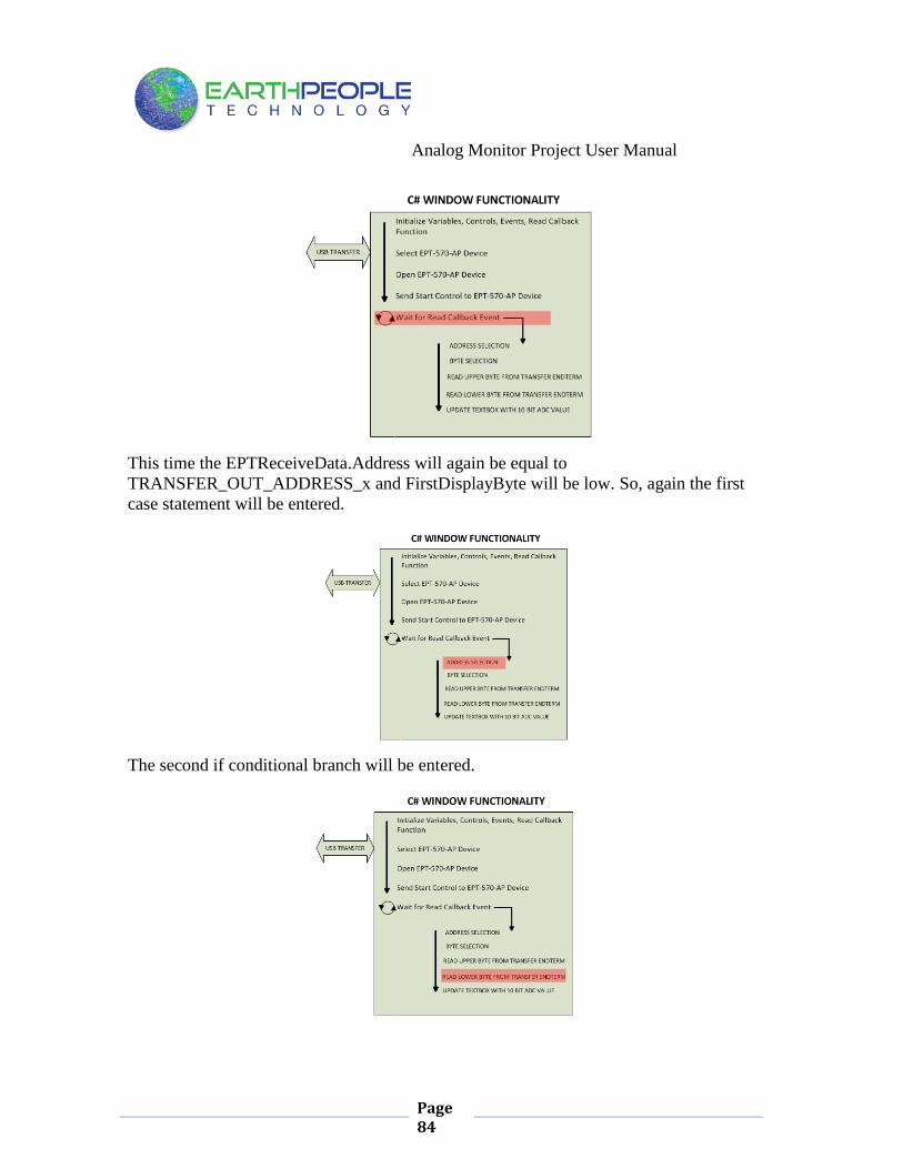
This time the EPTReceiveData.Address will again be equal to
TRANSFER_OUT_ADDRESS_x and FirstDisplayByte will be low. So, again the first
case statement will be entered.
The second if conditional branch will be entered.

Analog Monitor Project User Manual
Page 85
When it is entered, the following occurs:
1. The WriteRcvChar is cleared to zero. This is done to clear out any value that
was previously in there. This variable is used to collect the modified
AnalogValue and send it a thread to be written to the Textbox.
2. The FirstDisplayByte is set to true so that the next time the case statement
TRANSFER_OUT_ADDRESS_x is entered, the upper byte will be added to the
first 8 bits of AnalogValue.
3. The byte buffer EPTReceiveData.cBlockBuf[0] is added to AnalogValue. This
will store the lower byte from the EPT-570-AP to the lower 8 bits of
AnalogValue.
4. The ScaleFactorx variable is checked for nonzero value. If is zero, the
AnalogValue is converted to a string and stored in WriteRcvChar. This will pass
the raw counts from the output of the Arduino ADC channel into WriteRcvChar.
If the ScaleFactorx is nonzero, that tells the code that a scale factor is present
and the code must multiply this value by the raw counts from the Arduino ADC
channel. This is done by using a float value labeled: FloatValue. This value is
set to the result of AnalogValue multiplied by the ScaleFactorx.
5. The results of the scalefactor conditional branch is converted to a string then
stored in WriteRcvChar.

Analog Monitor Project User Manual
Page 86
6. The next several statements update the DisplayAddress_x variables. It sets the
current DisplayAddress_x to false and sets the next incremented
DisplayAddress_x to true. This is done so that the C# code can be synchronized
with the code on the Arduino.
7. Next, the WriteRcvChar value is sent to the thread that will populate the
textbox. Calling a thread is similar to calling a function. However, when you call
a function in the traditional C language, the calling instruction is halted while
the function instructions are executed. When the function is complete, the
execution is handed back to the calling instruction and it continues to execute
and the next instruction after that is executed and so on. When a thread is
commanded to execute, the Windows OS will execute instructions for the
function in the thread and simultaneously continue execution of instructions in
the calling code. The Windows OS allows hundreds of threads to execute
simultaneously. It maintains the memory and execution requirements for each
thread transparently to the user. C# is brilliant because you can easily call a
thread and forget about it. It handles everything for you, it even cleans up the
memory after the thread has completed. So, to launch our “write to textbox”
thread, use the ParameterizedThreadStart() function. This allows us to pass an
object, “WriteRcvChar” to the function.
8. Finally, the textbox, “tbMonitor_x” is updated. This is done by using the
Invoke-Method instruction. A method is a function in a class. In winforms,
Invoke is used to call a method on the UI thread – without it can cause an
exception by updating the UI from another thread. Effectively, what Invoke does
is ensure that the code you are calling occures on the thread that the control
“lives on” effectively preventing cross threaded exceptions. Further, the .NET
framework creates multiple threads when using winforms. The textboxes “live”
on a controls thread, while your code to update the textbox “lives” on a user-
background thread. These two threads are not synchronized. So, your code must
ask the textbox thread (called the UI thread) politely if it could update the text

Analog Monitor Project User Manual
Page 87
characters in the box. The UI thread will decide when it is ready to stop and
handle the request from the background thread.
Once the Invoke—Method has been called the EPTTransferOut thread is complete and
the textbox will be updated with the 10 bit digitized sample from the Arduino selected
channel.
Then repeat the above steps for the rest of the five channels.
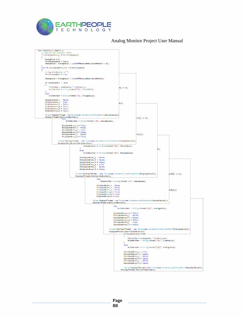
Analog Monitor Project User Manual
Page 88

Analog Monitor Project User Manual
Page 89
Now that we have the code to perform the decode, store the digitized value and display
to textbox, we need to add error correction code. This code is added to handle the case
in which we start up the Analog Monitor C# code and we don’t know what channel or
which byte (upper/lower) is being received.
We add two conditional branches to the case statement of
TRANSFER_OUT_ADDRESS_x. These two branches will handle the case when
DisplayAddress_x is low. This means that for the EPTReceiveData.Address received,
the DisplayAddress_x was not set to the correct address previously.
We will need several variables to accomplish error correction. These variables are:

Analog Monitor Project User Manual
Page 90
The DisplayAddress_x variables are used to check whether the Arduino channel
number and the C# code are in sync. The FirstPreviousActualAddr and
SecondPreviousActualAddr are used to record the previous two Arduino channel
selections. The FirstPreciousCalcAddr and SecondPreviousCalcAdddr are used to
record the address’s that the C# code calculates in response to
EPTReceiveData.Address and conditional branches.
In the first error correction branch, EPTReceiveData.Address will select a case
statement with TRANSFER_OUT_ADDRESS_x but the DisplayAddress_y is not the
same value. The FirsDisplayByte is high, so the following happens.
1. Each time a byte is received, SecondPreviousActualAddr is set to
FirstPreviousActualAddr. Also, FirstPreviousActualAddr is set to
EPTReceiveData.Address. This ensures that the older address is in the Second…
and the newest address is in First…
2. Set FirstPreviousCalcAddr to EPTReceiveData.Address.
3. Set FirstDisplayByte to false or low.
4. Set AnalogValue to zero
5. Set DisplayAddress_x to high. This will select the current address of
EPTReceiveData.Address. This assumes that the current selection of
EPTReceiveData.Address is the upper byte of the digitized value and the
following selection of EPTReceiveData.Address will be the lower byte. If that is
the case then we will be in sync with the Arduino channel selection and no
further error correction will be needed.
In the second error correction branch, EPTReceiveData.Address will select a case
statement with TRANSFER_OUT_ADDRESS_x but the DisplayAddress_y is not the
same value. The FirsDisplayByte is low, so the following happens.
1. Set SecondPreviousCalcAddr equal to the incremetn of
EPTReceiveData.Address. This makes the assumption that the next byte
transferred will be the upper byte of the digitized value and that means that the
address will be incremented.

Analog Monitor Project User Manual
Page 91
2. FirstDisplayByte is set to true.
3. AnalogValue is set to zero.
4. A conditional branch is used to check if the FirstPreviousActualAddr is equal to
FirstPreviousCalcAddr. Also SecondPreviousActualAddr is checked for
equivalency with SecondPreviousCalcAddr. This is done to check the history of
the address’s that have been used to get to this conditional branch. If the history
is congruent, then the DisplayAddress_x will be set to the next address. If the
history is not congruent, DisplayAddress_x will be set to the current address.
This is all that is necessary to synchronize the Arudino channel selection and the C#
display functions. Use the table below to verify that the error correction code will
synchronize with the Arduino channel no matter what the channel is or whether the C#
code is receiving the upper digitized byte or lower digitized bye.
5.1.10 C# Project Scale Factor Selection
When both the upper and lower bytes have been received from the EPT-570-AP, the
AnalogValue has the ADC counts from the Arduino channel. But this is just a digital
representation of the analog signal sampled at the ADC input. To convert this into a real
voltage, we have to multiply the raw counts by the scale factor. First we need to
calculate what the scale factor should be. This is accomplished by taking the full scale
deflection of the ADC, this means the maximum voltage the ADC can take, for the
Arduino Uno it is 5 Volts. Then divide this number by the total number of counts of the
ADC, for the Arduino Uno’s 10 bit ADC, this is 210
= 1024. So, the scale factor is
5V/1024Counts. Our scale factor is 0.0048828 Volts/Counts. To set the scale factor for
each Arduino channel digitized value, we added all the code to file ScaleFactorMenu.cs.
The top of the file declares the namespace to add the code to, and the class that is
belongs to.

Analog Monitor Project User Manual
Page 92
This code is activated when the
button is clicked. It calls the ScaleFactorMenuOpenWindow() function.
The code will expand the WinForm and add textboxes, buttons, and labels at run time.
The code looks the same as if we used the ‘drag and drop’ method from the Visual
Studio Toolbox.
Each textbox is setup with the following code.
Each button and label is setup with the following code.

Analog Monitor Project User Manual
Page 93
When all of the textboxes, buttons, and lables are set up, the
ScaleFactorMenuSetAnchor() function is called. This makes sure that all controls are
pinned to the top left corner of the Winform. If the user resizes the window, all of the
controls: textboxes, buttons, and labels will get resized along with the main Winform.
When the window is complete at runtime it will look like:
To add a value to the ScaleFactor_x textbox, just type in the number. The “KeyPress”
event will be raised by typing in the textbox. We add a subsctiption to this event. When
the event occurs, we execute our code to retreive the scale factor value.
For more information about events and how to subscribe to them, see this web page.
http://www.homeandlearn.co.uk/csharp/csharp_s9p1.html

Analog Monitor Project User Manual
Page 94
When we execute our code, the ScaleFactorX is set equal to the string value of the
textbox, ScaleFactorXTextBox.Text. This means the number retrieved from the textbox
is in the wrong format, ie a string. So, we need to convert the string into a float value for
use as a scale factor. To do this, use the “Convert.ToDouble” method. Then recast the
double as a float, ScaleFactorX =
(float)Convert.ToDouble(ScaleFactorXTextBox.Text);
Repeat this KeyPress event for all six ScaleFactor textboxes.
Once the ScaleFactor is updated, it will be multiplied by the AnalogValue for the
appropriate channel on the next display textbox update for the given channel.

Analog Monitor Project User Manual
Page 95
The ScaleFactorExitButton_Click event calls the shutdown of the ScaleFactor Menu. It
disposes of textboxes, buttons, and labels and resets the Winform to its original
dimensions.
5.1.11 C# Project Completion
This is all that is needed for the Analog Monitor project. The Arduino will generate a 10
bit digitized word for each channel. It then transmits that word to the CPLD using the
Write_Enable, Address and data pins. The CPLD transmits each 10 bit word to the PC
using the Active_Transfer EndTerm, Active_Transfer Library, and One Hot State
Machine. The dll reads the 10 bit word into local memory. It then calls the Callback
function, EPTReadFunction. Each 10 bit value is finally displayed to screen using the
TransferOutReceive() function.
5.2 PC: Compiling the Active Host Application Building the Analog_Monitor project will compile the code in the project and produce
an executable file. It will link all of the functions declared in the opening of the
Analog_Monitor Class with the Active Host dll. The project will also automatically link
the FTD2XX.dll to the object code.
To build the project, go to Debug->Build Solution.

Analog Monitor Project User Manual
Page 96
The C# Express compiler will start the building process. If there are no errors with code
syntax, function usage, or linking, then the environment responds with “Build
Succeeded”.
If the build fails, you will have to examine each error in the “Error List” and fix it
accordingly. If you cannot fix the error using troubleshooting methods, post a topic in
the Earth People Technology Forum. All topics will be answered by a member of the
technical staff as soon as possible.
5.2.1 Adding the DLL’s to the Project
Locate the UNO_ANALOG_MONITOR_PROJECT_CD installed on your PC. Browse
to the Projects_ActiveHost folder (choose either the 32 bit or 64 bit version, depending
on whether your OS is 32 or 64 bit). Open the Bin folder, copy the following files:
ActiveHostXX.dll
ftd2xxXX.dll
and paste them in the EPT_Analog_Monitor\EPT_Analog_Monitor\bin\x64\Release
folder of your EPT_Analog_Monitor project.

Analog Monitor Project User Manual
Page 97
At this point, the environment has produced an executable file and is ready for testing.
Next, we will connect everything together and see it collect data and display it.
6 Connecting the Project Together Now we will connect the Arduino, EPT 570-AP-U2, and the PC to make an Analog
Monitor. First, connect a USB cable from a USB port on the PC to the Arduino. Second,
connect a USB cable from a open USB port on the PC to the EPT 570-AP-U2.
Next, let’s connect the Six 5VDC Power Supplies to the analog inputs of the Arduino.
We will do the by using the following parts:
6 Pin 2.54 mm Male Header
10 Pin 2.54 mm Male Header
Six 5VDC Power Supplies
Five Black Banana Lead jumpers to connect the Power Supplies together
One Black Banana Clip Lead to connect the Power Supplies to the Arduino
Six Red Banana Clip Leads to connect the Power Supplies to the Arduino
Connect the 10 Pin 2.54 mm Male Header into the J12 connector of the EPT-570-AP
board. Next, connect the 6 Pin 2.54 mm Male Header into the J9 connector of the EPT-
570-AP board. Connect the black banana jumpers between the grounds of all the
supplies. Connect the black banana clip lead to one of the power supply grounds and
Pin 7 of J12. Connect one red banana clip lead to each of the power supply positive
outputs and connect to one of the pins on the J9 connector.
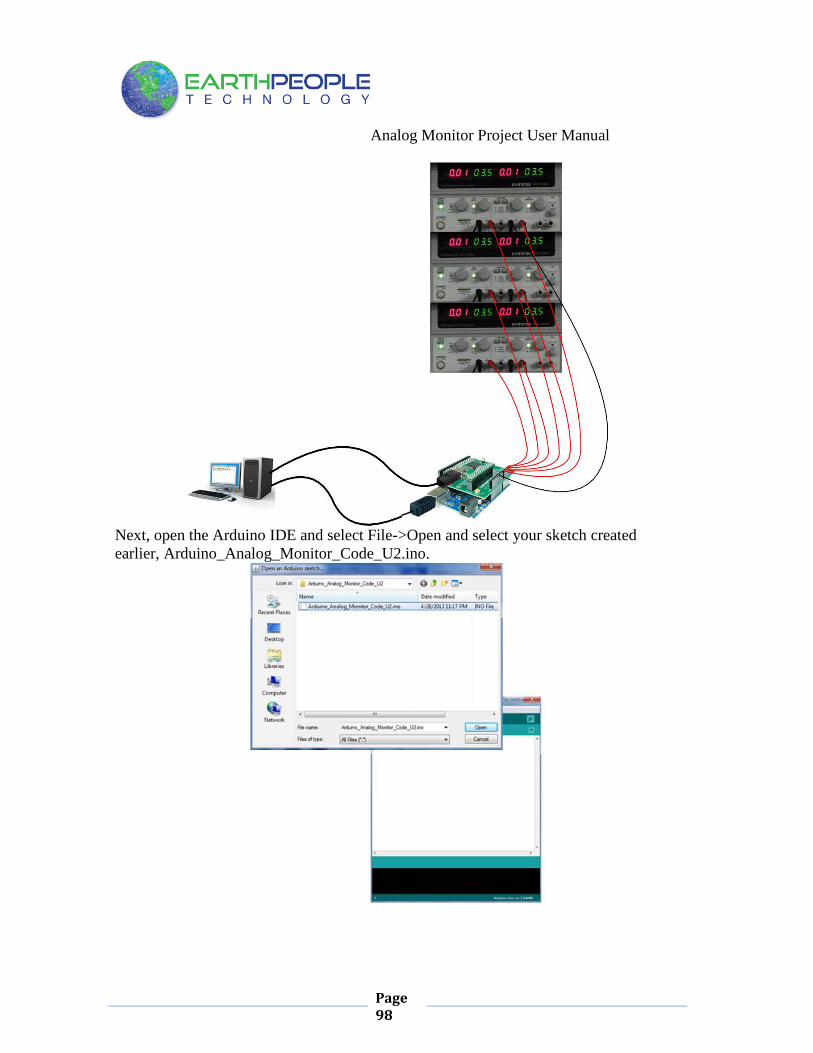
Analog Monitor Project User Manual
Page 98
Next, open the Arduino IDE and select File->Open and select your sketch created
earlier, Arduino_Analog_Monitor_Code_U2.ino.

Analog Monitor Project User Manual
Page 99
Select the file and click Open. The sketch will now populate the Arduino IDE window.
Compile and Download the sketch into the Arduino microcontroller using the Upload
button.
The Arduino IDE will compile the project, then transmit the machine level code into the
ATMega328 SRAM to start the program.
The CPLD should already be programmed with its Analog Monitor Project.
Open the EPT Analog Monitor on the PC by browsing to the Analog Monitor project
folder. Locate the executable in the \bin\x64\Release folder.
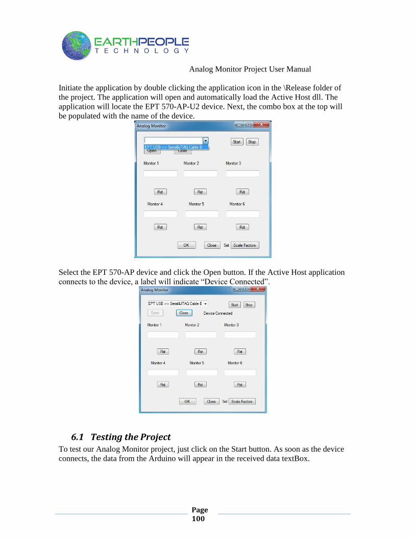
Analog Monitor Project User Manual
Page 100
Initiate the application by double clicking the application icon in the \Release folder of
the project. The application will open and automatically load the Active Host dll. The
application will locate the EPT 570-AP-U2 device. Next, the combo box at the top will
be populated with the name of the device.
Select the EPT 570-AP device and click the Open button. If the Active Host application
connects to the device, a label will indicate “Device Connected”.
6.1 Testing the Project To test our Analog Monitor project, just click on the Start button. As soon as the device
connects, the data from the Arduino will appear in the received data textBox.

Analog Monitor Project User Manual
Page 101
Turn on all six of the 5VDC Power Supplies. Click on the “Set Scale Factors” button.
Type the scale factor for each Monitor textbox in the corresponding ScaleFactor
textbox. The scale factor is 5V/1024Counts. Our scale factor is 0.0048828
Volts/Counts.

Analog Monitor Project User Manual
Page 102
And that’s all there is to the Analog Monitor Project. It’s up to the user to use this
project as a base to create much larger projects. You can easily make a volt meter using
this project by turning off the Random number generator in the Arduino and reading the
Analog Pins. Also, reformat the textBox display that it shows in decimal instead of the
Hexadecimal display.


![Jisc Monitor Pilot Project Proposal Final 14032014[4]€¦ · Jisc%Monitor%Pilot%Project%Proposal%from%Mimas% " " " " " " "](https://img.pdfslide.net/doc/110x75/5f13202bcd0570065163318e/jisc-monitor-pilot-project-proposal-final-140320144-jiscmonitorpilotprojectproposalfrommimas.jpg)