Embed Size (px)
Citation preview

1
Earth Station Equipment
Cyril Sayegh
Customer Solutions Engineer
ITSO Cairo
Sept 2014
2
RF Chain diagram

3
Uplink and Downlink path
4
Flexible Waveguide OMT Feed
RX output,horizontal
LNB
Outdoor units
TRF
TX input,vertical

5
Uplink Block Diagram• Modulator / Modem
• Up-Converter
• Power Amplifier
• Antenna
• Inter Facility Link (IFL)
• Fiber Optics
• Co-axial cable Combiners / Splitters
• Waveguide

6
Uplink Block Diagram• Modulator / Modem
• Up-Converter
• Power Amplifier
• Antenna
• Inter Facility Link (IFL)
• Fiber Optics
• Co-axial cable Combiners / Splitters
• Waveguide

7
Modems - Selection• SCPC
• Low Throughput 64Kbps
• High Throughput >300Mbps
• Carrier Cancellation
• TDM/TDMA
• Simple Hubless solution
• Star Network
• Mesh network
• Advanced features
• Roll Off

8
Modem Interfaces
• RS232/RS422
• HSSI/G703/Ethernet
• D-Type connector, BNC, Ethernet
• IDR G703 E1/T1
• IBS: RS422/RS232/ITU.V35
• ASI
• Ethernet
• SDI

9
Common Modulation TechniquesA sinusoid has 3 different parameters that can be varied. These are amplitude,
phase and frequency.
The three basic types of digital modulation are :
• Amplitude Shift Keying (ASK)
• Frequency Shift Keying (FSK)
• Phase Shift Keying (PSK)
Some Old analog modulations: AM, FM..
Popular modulation types used for satellite communications:
(BPSK) Binary; (QPSK) Quadrature; 8PSK; (QAM)especially 16QAM

10
Amplitude Modulation (AM)
Vary the Amplitude
In AM modulation, the voltage (amplitude) of the carrier is varied by the incoming signal. In this example, the modulating wave implies an analog signal.
AM is also used for digital data. In quadrature amplitude modulation (QAM), both amplitude and phase modulation are used to create different binary states for transmission.

11
Digital 8QAM
In this 8QAM example, three bits of input generate eight different modulation states (0-7) using four phase angles on 90 degree boundaries and two amplitudes: one at 50% modulation; the other at 100% (4 phases X 2 amplitudes = 8 modulation states). QAM examples with more modulation states become extremely difficult to visualize.

12
Digital Amplitude Shift Keying (ASK)
For digital signals, amplitude shift keying (ASK) uses two voltage levels for 0 and 1 as in this example.

13
Frequency Shift Keying (FSK)
FSK is a simple technique that uses two frequencies to represent 0 and 1.

14
Phase Shift Keying (PSK)
For digital signals, phase shift keying (PSK) uses two phases for 0 and 1 as in this example.
PSK offers excellent performance and makes multi-phase modulation available. PSK is the method most commonly used in digital satellite communication systems.

15
Quadrature Phase Shift Keying (QPSK)
QPSK uses four phase angles to represent each two bits of input; however, the amplitude remains constant.

16
Phase Shift Key
• QPSK – 2 bits per symbol
• 8PSK – 3 bits per symbol
• 16APSK – 4 bits per symbol
• 32APSK – 5 bits per symbol
• etc

17
Uplink Block Diagram• Modulator / Modem
• Up-Converter
• Power Amplifier
• Antenna
• Inter Facility Link (IFL)
• Fiber Optics
• Co-axial cableCombiners / Splitters
• Waveguide

18
Up-Converter (U/C)
•The method used to achieve the conversion is heterodyning. That is the mixing of two different frequencies into a non-linear device ( mixer ) to produce two other frequencies equal to the sum or difference of the first two, while maintaining it’s characteristics
� A device that converts an input signal known as the intermediate frequency (IF) to a desired higher frequency without disturbing the intelligence (modulation) on the incoming signal

19
Up-Converter (U/C)
• 140 MHz to L-Band
• 140 ±72 MHz input
• 950 – 1450 MHz output
• Non inverting
• 72 MHz bandwidth
� 70 / 140 MHz IF to L-Band
– 70 MHz to L-Band• 70 ±18 MHz input
• 950 – 1450 MHz output
• Non inverting
• 36 MHz bandwidth

20
Up-Converter (U/C)
•L-Band to C-Band• 950 - 1450 MHz input
• 5.925 – 6.425 GHz output
• Non inverting (4.900 GHz LO)
• Inverting (7.375 GHz LO)
• 500 MHz bandwidth
� L-Band to Ku-Band– 950 - 1450 MHz input
– 14.00 – 14.50 GHz output
– Non inverting (LO = 13.050 GHz)
– Inverting (LO = 15.450 GHz)
– 500 MHz bandwidth

21
Up-Converter (U/C)
•70 MHz to C-Band• 70 ±18 MHz input
• 5.850 – 6.425 GHz output
• Non inverting
• 36 MHz bandwidth
• 140 MHz to C-Band• 140 ± 36 MHz input
• 5.850 – 6.425 GHz output
• Non inverting
• 72 MHz bandwidth

22
Up-Converter (U/C)
•70 MHz to Ku-Band• 70 ±18 MHz input
• 14.00 – 14.50 GHz output
• Non inverting
• 36 MHz bandwidth
� 140 MHz to Ku-Band– 140 ± 36 MHz input– 14.00 – 14.50 GHz output– Non inverting– 72 MHz bandwidth

23
Uplink Block Diagram• Modulator / Modem
• Up-Converter
• Power Amplifier
• Antenna
• Inter Facility Link (IFL)
• Fiber Optics
• Co-axial cableCombiners / Splitters
• Waveguide

24
Power Amplifiers
• High Power Amplifiers - HPA
• Solid State Power Amplifiers - SSPA
• Travelling Wave Tube – TWT
• Klystron Power Amplifier KPA
• Including/excluding Up-conversion
• Transceivers

25
Transceiver• Combination Power Supply, Up / down converter, HPA and
LNA - PSU
• Mounted on / at the antenna
• 70 or 140 MHz or L-Band input
• RF Output C/Ku/Ka-Band output
• Single or dual synthesized converters
• Uplink
• Downlink

26
Solid State Power Amplifiers• Typical output power 5 to 200 Watts
• 500 MHz bandwidth
• Non Linear
• L-Band Up-Converter optional
• Requires external 10 MHz reference
• Requires Diplexer
• Typically ≈ 3 dB OBO for multi carrier operation

27
Solid State Power Amplifiers
• Lower Power 1- 200W
• Lower OBO for multicarrier operation
• Cost effective
• Low maintenance
• Power efficient
• Susceptible to power and lightning damage

28
Travelling Tube Amplifier– Typical output power 100 – 750 Watts
– 500MHz - 750 MHz bandwidth
– Non Linear
– Built in BUC optional
• Requires 10 MHz external reference and Diplexer
– ≈ 7 dB OBO for multi carrier operation
– ≈ 4 dB OBO with linearizer for multi carrier operation

29
Transmitters (HPA)
• HPA HIGH POWER AMPLIFIER
• TRAVELING WAVE TUBE AMPLIFIER
• WIDEBAND ( FULL SPECTRUM ) GREATER 500MHz
• NON LINEAR
• SMALL SIGNAL SUPRESSION
• AMPLITUDE TRANSFER CURVE

30
Travelling Wave Tube Amplifiers
• Medium Power 200W – 750W
• Phase combined
• Also available in higher power
• Wideband >500MHz
• 4dB to 7dB OBO multicarrier operation
• Dependent on linearizers fitted
• Medium maintenance
• Medium robustness to lightning damage and
reflections

31
Transmitters (HPA)
• SMALL SIGNAL SUPRESSION
• AMPLITUDE TRANSFER CURVE
• INTERMODULATIONf 1 - f 2 f 1 + f 2f1 f2
( f 1 - f 2 ) - f 1

32
Klystron Power Amplifier
– Typical output power 1000 to 3000 Watts– Non linear– 40 or 80 MHz bandwidth– OBO ≈ 2 dB for dual carrier operation
≈ 7 dB for multi carrier operation
33
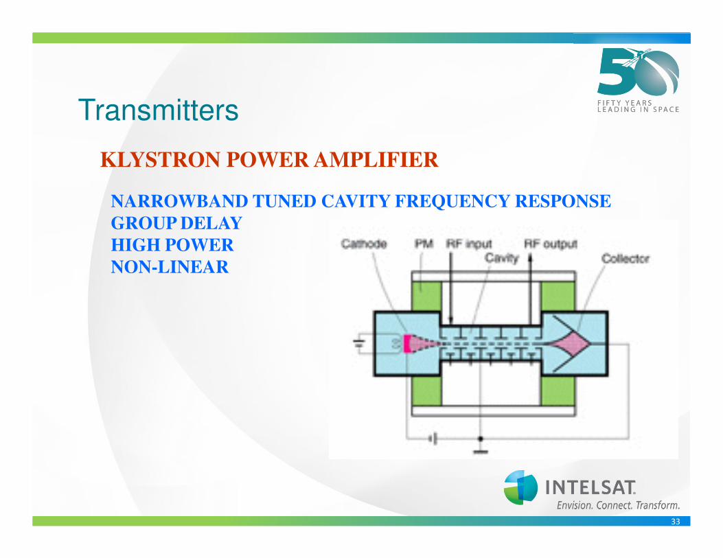
Transmitters
KLYSTRON POWER AMPLIFIER
NARROWBAND TUNED CAVITY FREQUENCY RESPONSE
GROUP DELAY
HIGH POWER
NON-LINEAR

34
Klystron Power Amplifiers
• High Power 1000 – 30000W
• Narrowband approx. 80MHz
• 7dB OBO - multicarrier operation
• High maintenance and high operations costs
• High level skills and equipment needed to
operate - tuning
• High to lightning damage and reflections
• Power hungry

35
Uplink Block Diagram• Modulator / Modem
• Up-Converter
• Power Amplifier
• Antenna
• Inter Facility Link (IFL)
• Fiber Optics
• Co-axial cable Combiners / Splitters
• Waveguide

36
Inter Facility Linking
• Co-axial cabling
• Data and base band
• IF
• L-Band
• C-Band
• Ku-band
37
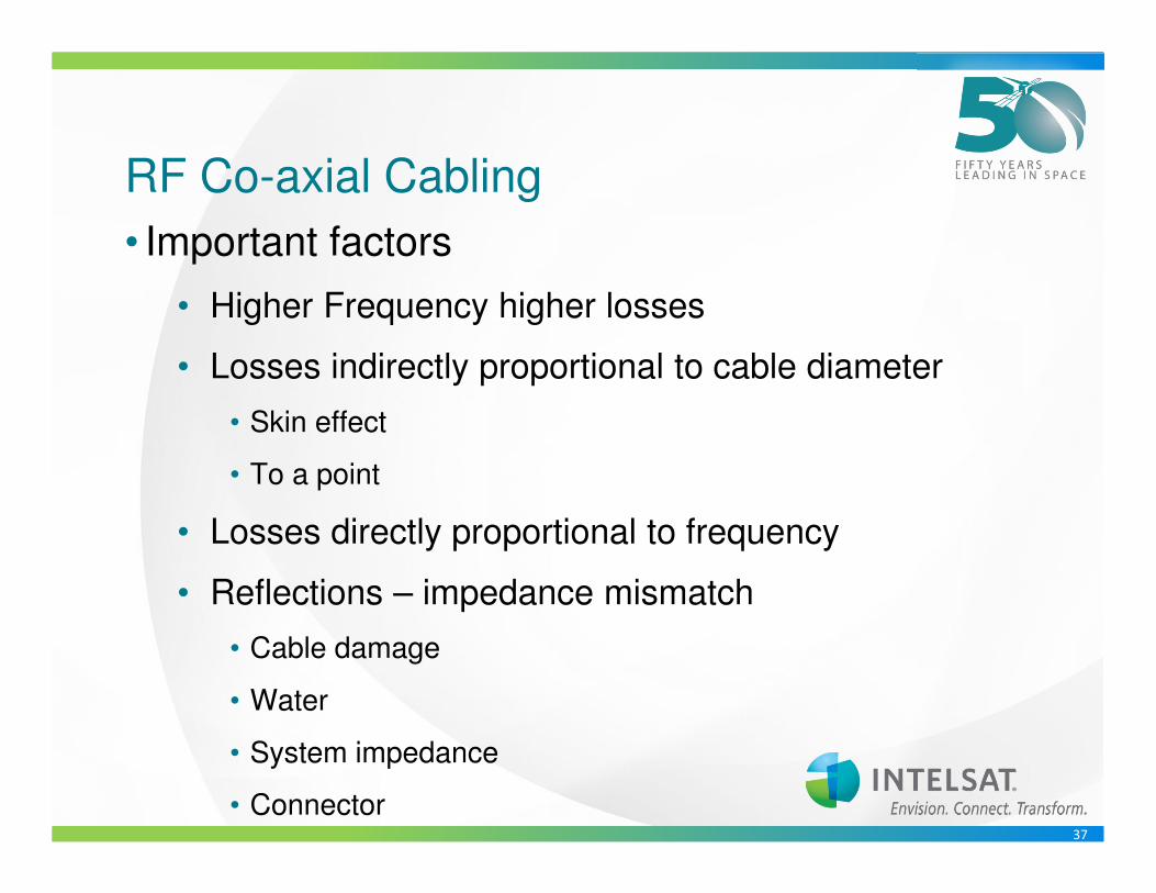
RF Co-axial Cabling
• Important factors
• Higher Frequency higher losses
• Losses indirectly proportional to cable diameter
• Skin effect
• To a point
• Losses directly proportional to frequency
• Reflections – impedance mismatch
• Cable damage
• Water
• System impedance
• Connector

38
Waveguide
• Used at C-Band and higher frequencies
• Lower loss than co-axial cable
• Types:
• Rigid
• Flexible, Flexible and twistable
• Elyptical
• Not wideband – Frequency determines
dimension

39
Combiners Small Signal
• Types
• IF
• L-band
• C-Band/Ku-band
• Considerations
• Losses
• Impedance matching
• Terminating unused ports

40
Combiner - Wideband
• 3dB Coupler
• Co-axial
• Waveguide
• High power
• Wideband
• 3dB loss Dummy load required

41
Combiner - Filter
• Co-axial
• Waveguide
• Variances
• One port wideband
• Other port narrowband
• Low insertion losses

42
Patch Panels
8:1
IF Patch Panel
Modem
Modem
Modem
Modem
DATAPatch Panel
1:8
Up-Converter
Down-Converter
1:2HPA
1:2 LNA
10 dB
Coupler40 dB
Coupler
50 dB
Inject
Coupler
IF Patch Panel
TP-1 TP-2
TP-3TP-4
Uplink & Downlink Patch Panel and RF monitor block diagram
– 10 dB coupler on Up-Converter output (TP-1)
• Monitor Up-converter output
– 40 dB coupler at feed input (TP-2)
• Monitor aggregate transmit carriers and power
– Receive inject coupler (TP-3)
• Capability to inject carrier prior to LNA
– Ability to calibrate downlink chain
- Splitter at Down-Converter input (TP-4)
- Monitor full 500 MHz downlink spectrum

43
Downlink Components
• Demodulator / Modem
• Down-Converter
• LNA
• Antenna
• Inter Facility Link (IFL)
• Fiber Optics
• Co-axial cable
• Patch Panels
• Combiners / Splitters
• Waveguide

44
Low Noise Amplifier (LNA)
• Lower the Noise Temperature, the better the performance
� Input Waveguide– CPR-229 C-Band– WR-75 Ku-Band
� Output Coaxial connector– N-Type (50 ohm) Standard C-Band– SMA (50 ohm) Standard Ku-Band
� Typical 3 stage amplification (Designed to keep noise down)– No Frequency Conversion
� “Noise Temperature” is the amount of noise added – Specified in degrees K for C-Band
• 20o – 40oK Typical
– Specified as Noise Figure (NF) for Ku-Band
• 0.7 to 1.0 Typical (50o – 75oK)

45
Low Noise Block Down-Converter (LNB)
•Output Coaxial connector• N-Type (50 ohm)
• F-Type (75 ohm)
Low Noise Amplifier
DC Regulator
Input Output
Power
� LNA with a Block Down-Converter built in� Provides Frequency Conversion
– DRO (Dielectric resonator Oscillator) • ± 150 kHz to ± 500 kHz C-Band• ± 150 kHz to ± 900 kHz Ku-Band
– PLL (Phase Locked Loop)• ± 5 kHz to ± 25 kHz C-Band• ± 5 kHz to ± 50 kHz Ku-Band
– External (10 MHz reference)
� Input Waveguide
– CPR-229 C-Band
– WR-75 Ku-Band

46
PLL vs DROPLL stands for Phased Locked Loop
DRO is Dielectric Resonator Oscillator
PLLs are more stable than DROs, as they use a more stable internal reference source (crystal oscillators) or an input from a stable external source (rubidium clock, analog 10MHz signal source, etc)
For low bitrates or small carriers DRO provides a better solution.
DROs are OK to receive large bitrate carriers (such as DVB multiplexes for instance).
Advantages of DROs are price as it is very cheap.

47
Low Noise Amplifier (LNA/LNB)
• Frequency stability of LNB critical depending on type of service
� Designed to provide the lowest noise contribution as possible– 20o – 40o K noise temperature typical for C-band
– 70o – 90o K noise temperature typical for Ku-band
– 50 to 60 dB Gain typical
� Mounted as close as possible to the OMT waveguide ports
� One of the most critical components of an antenna system– Major factor in determining the systems figure of merit (G/T)

48
Down-Converter (D/C)
•A device that converts an RF input signal to a desired lower frequency known as the intermediate frequency (IF) without disturbing the intelligence (modulation) on the incoming signal
•The method used to achieve the conversion is heterodyning. That is the mixing of two different frequencies into a non-linear device ( mixer ) to produce two other frequencies equal to the sum or difference of the first two, while maintaining it’s characteristics

49
D/C Frequency Calculations
• Modem IF Frequency = 1270.5 MHz (5150 – 3879.5)
• LNB LO freq (-) Downlink freq
� C-band to L-Band– Inverted C-Band (LNB)
– LO frequency of the LNB (5150 MHz)
– Carrier Downlink Frequency 3879.5 MHz

50
• Carrier Downlink Frequency 11907.5 MHz
D/C Frequency Calculations
� Ku-Band to L-Band– Non Inverted Ku-Band (LNB)– LO frequency of the LNB (10750 MHz)
– Modem IF Frequency = 1157.5 MHz (11907.5 – 10750)– Downlink freq (-) LNB LO freq

51
D/C Frequency Calculations
• Modem IF Frequency = 65.5 MHz (5150 – 3879.5 -1275 +70)
• LNB LO freq (-) Downlink freq (-) D/C center freq (+) 70 MHz
� Inverted C-Band (LNB)
– Center Frequency of transponder (3875 MHz)
– LO frequency of the LNB (5150 MHz)– Center frequency of Down-Converter = 1275 MHz (5150 – 3875)
– LNB LO freq (-) Bandwidth center freq
– Carrier Downlink Frequency 3879.5 MHz

52
D/C Frequency Calculations
• Modem IF Frequency = 65.5 MHz (11907.5 – 10750 - 1150 +70)
• Downlink freq (-) LNB LO freq (-) D/C center freq (+) 70 MHz
� Non Inverted Ku-Band (LNB)
– Center Frequency of transponder (11900 MHz)
– LO frequency of the LNB (10750 MHz)– Center frequency of Down-Converter = 1150 MHz (11900 – 10750)
– Bandwidth center freq (-) LNB LO freq
– Carrier Downlink Frequency 11907.5 MHz

53
D/C Frequency Calculations
• Modem IF Frequency = 74.5 MHz (3879.5 – 3875 + 70)
• Downlink freq (-) U/C center freq (+) 70 MHz
� C-Band (70 MHz)– Center Frequency of transponder (3875 MHz)
– Center frequency of Down-Converter = 3875 MHz
– Carrier Downlink Frequency 3879.5 MHz

54
D/C Frequency Calculations
– Modem IF Frequency = 144.5 MHz (3879.5 – 3875 + 140) – Downlink freq (-) U/C center freq (+) 140 MHz
� C-Band (140 MHz)– Center Frequency of transponder (3875 MHz)
– Center frequency of Down-Converter = 3875 MHz
– Carrier Downlink Frequency 3879.5 MHz

55
D/C Frequency Calculations
• Ku-Band (70 MHz)
– Modem IF Frequency = 77.5 MHz (11907.5 – 11900 + 70) – Downlink freq (-) U/C center freq (+) 70 MHz
– Center Frequency of transponder (11900 MHz)
– Center frequency of Down-Converter 11900 MHz
– Carrier Downlink Frequency 11907.5 MHz

56
D/C Frequency Calculations
• Ku-Band (140 MHz)
– Modem IF Frequency = 147.5 MHz (11907.5 – 11900 + 140) – Downlink freq (-) U/C center freq (+) 140 MHz
– Center Frequency of transponder (11900 MHz)
– Center frequency of Down-Converter 11900 MHz
– Carrier Downlink Frequency 11907.5 MHz

57
Earth Station Measurements

58
Intermodulation Distortion

59
Intermodulation Distortion

60
Linear/Non Linear Operating Point
It is defined as the output power level at which the actual
gain deviates from the small signal gain by 1 dB

61
System Gain
62
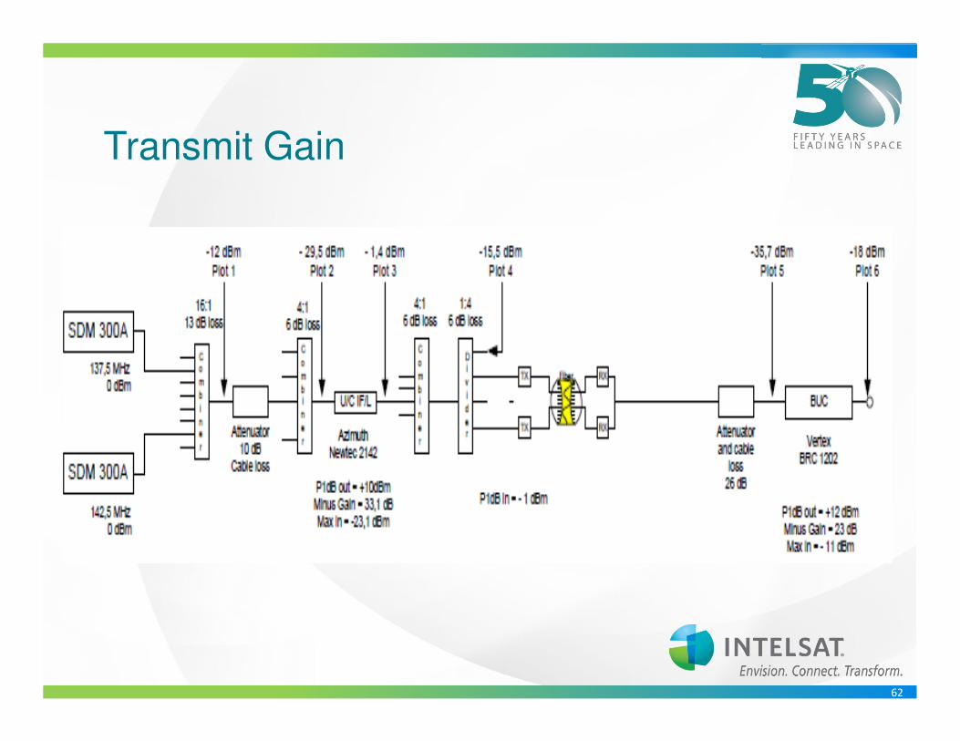
Transmit Gain

63
Best Practices

64
TX IFL/RF – Chain Measurement
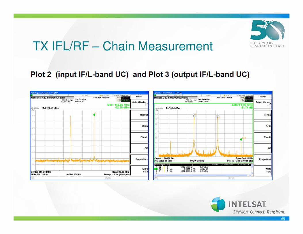
65
TX IFL/RF – Chain Measurement

66

67

68
Non Linear Effects on Digital Signals

69
Thank you !
Questions ?