Embed Size (px)
Citation preview
8/3/2019 Earthing a Brief Introduction
http://slidepdf.com/reader/full/earthing-a-brief-introduction 1/14
FIGURE 1
“EARTHING” A BRIEF INTRODUCTIONWHAT IS EARTHING?
“Earthing” may be described as a system of electrical connections to the general mass of earth. The characteristic primarily determining the effectiveness of an earth electrode is the resistance, which it provides between the earthingsystem and the general mass of earth.
PURPOSE OF EARTHINGThe earthing of an electrical installation has two purposes:
· To provide protection for persons or animals against the danger of electric shock.· To maintain the proper function of the electrical system.
THE CHIEF REQUIREMENT OF GOOD EARTHING IS LOW SOIL RESISTIVITY.Soil Resistivity (specific resistance of the soil) is usually measured in Ohm meters, one Ohm meter being the resistivity
the soil has when it has a resistance of one Ohm between the opposite faces of a cube of soil having one meter sides.
The other unit commonly used is the Ohm centimeter; to convert Ohm meters to Ohm centimeters, multiply by 100. Soilresistivity varies greatly from one location to another. For example, soil around the banks of a river has a resistivity in theorder o f1.5 Ohm meters. In the other extreme, dry sand in elevated areas can have values as high as 10,000 Ohm meters.
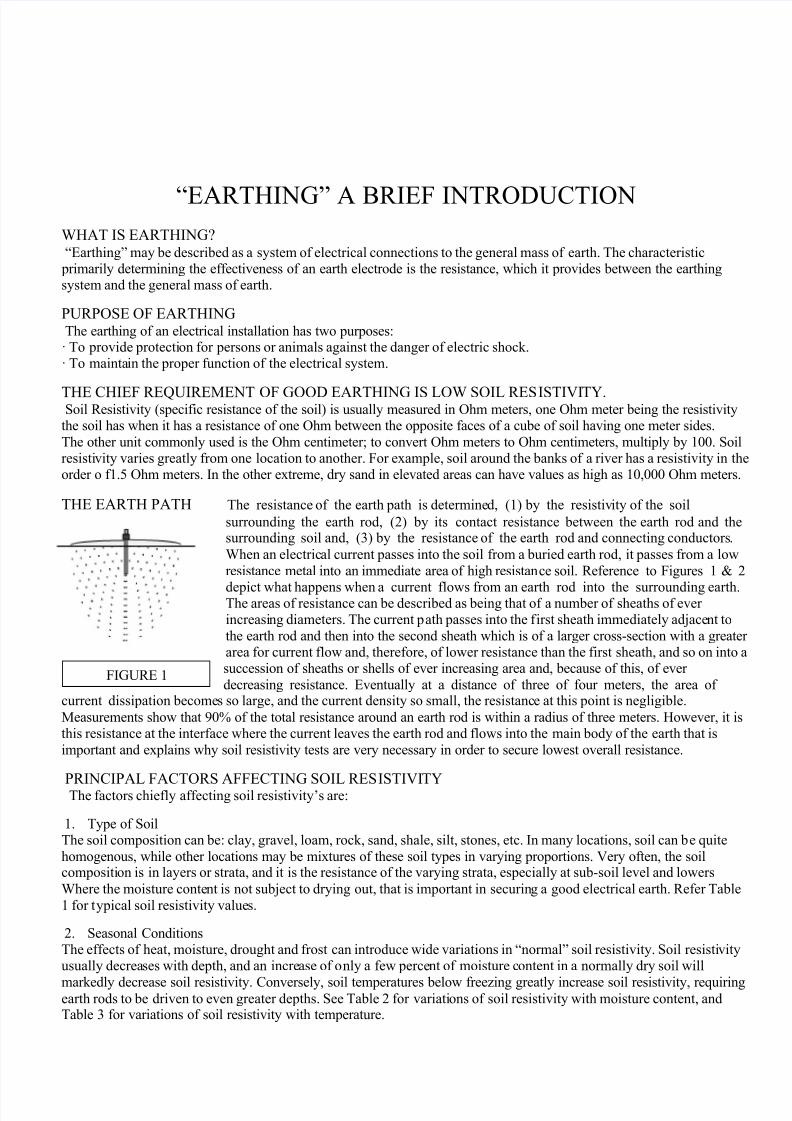
THE EARTH PATH The resistance of the earth path is determined, (1) by the resistivity of the soil
surrounding the earth rod, (2) by its contact resistance between the earth rod and thesurrounding soil and, (3) by the resistance of the earth rod and connecting conductors.
When an electrical current passes into the soil from a buried earth rod, it passes from a low
resistance metal into an immediate area of high resistance soil. Reference to Figures 1 & 2
depict what happens when a current flows from an earth rod into the surrounding earth.The areas of resistance can be described as being that of a number of sheaths of ever increasing diameters. The current path passes into the first sheath immediately adjacent to
the earth rod and then into the second sheath which is of a larger cross-section with a greater area for current flow and, therefore, of lower resistance than the first sheath, and so on into asuccession of sheaths or shells of ever increasing area and, because of this, of ever
decreasing resistance. Eventually at a distance of three of four meters, the area of current dissipation becomes so large, and the current density so small, the resistance at this point is negligible.
Measurements show that 90% of the total resistance around an earth rod is within a radius of three meters. However, it isthis resistance at the interface where the current leaves the earth rod and flows into the main body of the earth that is
important and explains why soil resistivity tests are very necessary in order to secure lowest overall resistance.
PRINCIPAL FACTORS AFFECTING SOIL RESISTIVITY The factors chiefly affecting soil resistivity’s are:
1. Type of SoilThe soil composition can be: clay, gravel, loam, rock, sand, shale, silt, stones, etc. In many locations, soil can be quite
homogenous, while other locations may be mixtures of these soil types in varying proportions. Very often, the soilcomposition is in layers or strata, and it is the resistance of the varying strata, especially at sub-soil level and lowers
Where the moisture content is not subject to drying out, that is important in securing a good electrical earth. Refer Table
1 for typical soil resistivity values.
2. Seasonal ConditionsThe effects of heat, moisture, drought and frost can introduce wide variations in “normal” soil resistivity. Soil resistivityusually decreases with depth, and an increase of only a few percent of moisture content in a normally dry soil will
markedly decrease soil resistivity. Conversely, soil temperatures below freezing greatly increase soil resistivity, requiringearth rods to be driven to even greater depths. See Table 2 for variations of soil resistivity with moisture content, andTable 3 for variations of soil resistivity with temperature.
8/3/2019 Earthing a Brief Introduction
http://slidepdf.com/reader/full/earthing-a-brief-introduction 2/14
3. Other FactorsOther soil properties conducive to low resistivity are chemical composition, soil ionization, homogeneous grain size and
even grain distribution - all of which have much to do with retention of soil moisture, as well as providing goodconditions for a closely packed soil in good contact with the earth rod. In view of all the above factors, there is a large
variation of soil resistivity between different soil types and moisture contents. Every earth is an individual and the onlyway to know that an earthing installation meets code requirements is to carry out proper resistance measurements on site.
Table 1
Resistivity Values for Several Types of Soils and WatersType of Soil or Water Typical Resistivity ohms/m Usual Limit WmSea Water 2 0.1 to 10
Clay 40 8 to 70Ground well and spring water 50 10 to 150Clay and sand mixtures 100 4 to 300Shale, slates, sandstone, etc 120 10 to 1000
Peat, loam and mud 150 5 to 250Lake and brook water 250 100 to 400
Sand 2000 200 to 3000
Moraine gravel 3000 40 to 10000Ridge gravel 15000 3000 to 30000Solid granite 25000 10000 to 50000Ice 100000 10000 to 100000
Table 2
Variations of Soil Resistivity with Moisture ContentMoisture Content Typical Value of Resistivity Wm
% of Weight Clay mixed with sand Sand0 10,000,000 -2.5 1,500 3,000,000
5 430 50,00010 185 2,100
15 105 63020 63 290
30 42 -
Table 3
Variation of Resistivity with Temperature in Mix of Sand, Clay with Moisture Content of 15% by Weight Temp. C Typical Value of Resistivity Wm20 72
10 990 (water) 1380 (ice) 300
-5 790-15 3,300
8/3/2019 Earthing a Brief Introduction
http://slidepdf.com/reader/full/earthing-a-brief-introduction 3/14
There are a variety of test instruments available; however, they can be generally categorized as three-terminal of four-terminal test instruments.
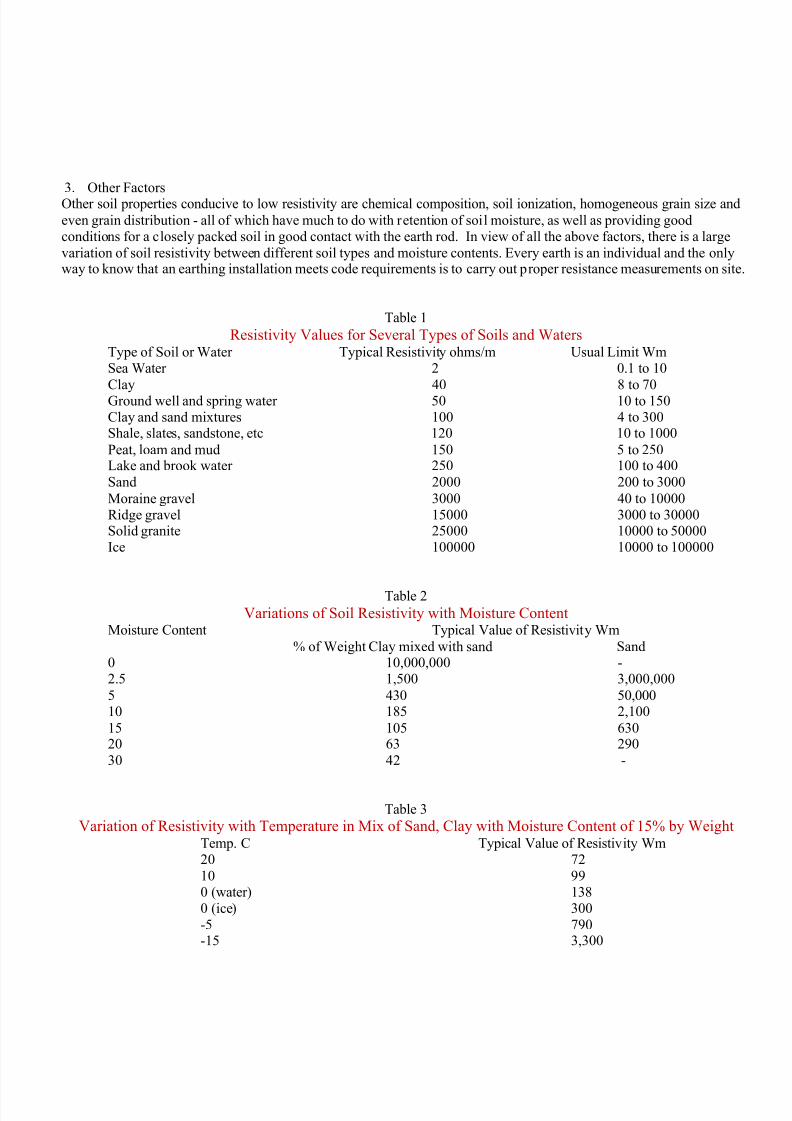
1. Measuring ResistanceFigure 3 illustrates the test setup for measuring the resistance in Ohms
between the installed earth rod and the general mass of earth. Refer
to the instrument manufacturer’s manual on how to carry out the test. As ageneral rule, the distance between the earth rod under test and the current
probe “C” is not less than 15 meters.
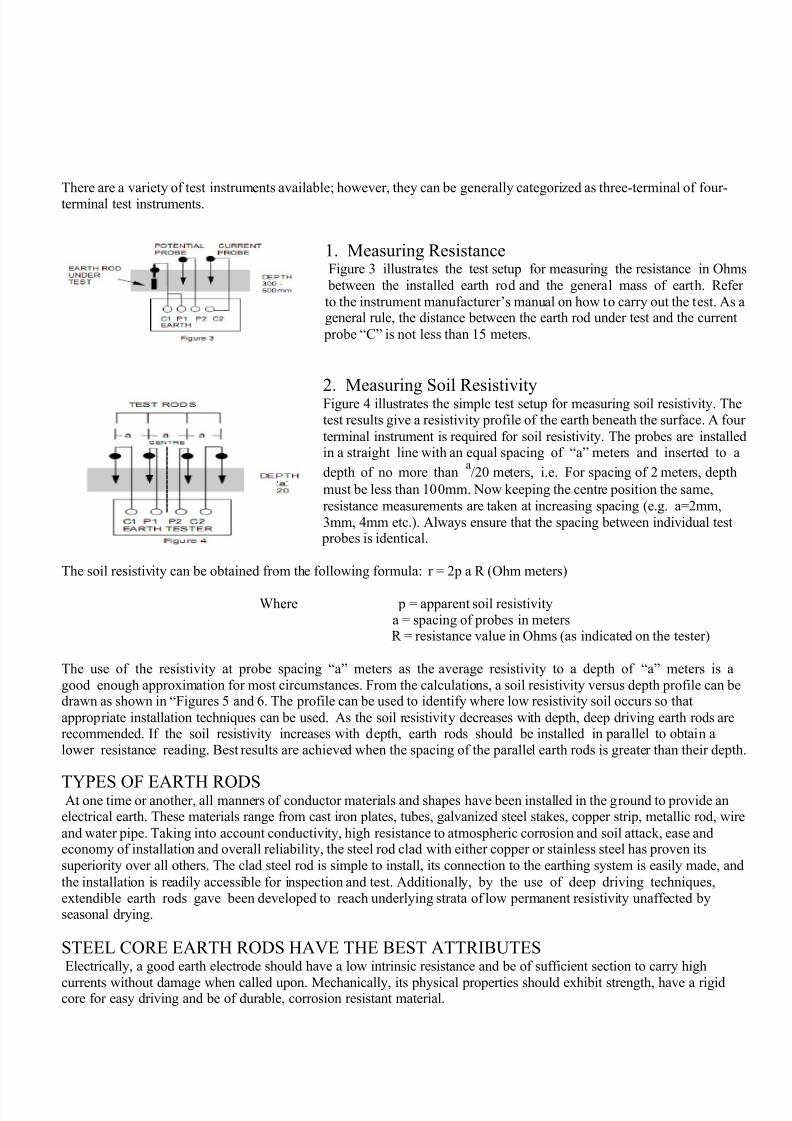
2. Measuring Soil Resistivity Figure 4 illustrates the simple test setup for measuring soil resistivity. Thetest results give a resistivity profile of the earth beneath the surface. A four
terminal instrument is required for soil resistivity. The probes are installedin a straight line with an equal spacing of “a” meters and inserted to a
depth of no more thana/20 meters, i.e. For spacing of 2 meters, depth
must be less than 100mm. Now keeping the centre position the same,
resistance measurements are taken at increasing spacing (e.g. a=2mm,
3mm, 4mm etc.). Always ensure that the spacing between individual test probes is identical.
The soil resistivity can be obtained from the following formula: r = 2p a R (Ohm meters)
Where p = apparent soil resistivitya = spacing of probes in metersR = resistance value in Ohms (as indicated on the tester)
The use of the resistivity at probe spacing “a” meters as the average resistivity to a depth of “a” meters is a
good enough approximation for most circumstances. From the calculations, a soil resistivity versus depth profile can bedrawn as shown in “Figures 5 and 6. The profile can be used to identify where low resistivity soil occurs so that
appropriate installation techniques can be used. As the soil resistivity decreases with depth, deep driving earth rods arerecommended. If the soil resistivity increases with depth, earth rods should be installed in parallel to obtain alower resistance reading. Best results are achieved when the spacing of the parallel earth rods is greater than their depth.
TYPES OF EARTH RODSAt one time or another, all manners of conductor materials and shapes have been installed in the ground to provide an
electrical earth. These materials range from cast iron plates, tubes, galvanized steel stakes, copper strip, metallic rod, wire
and water pipe. Taking into account conductivity, high resistance to atmospheric corrosion and soil attack, ease andeconomy of installation and overall reliability, the steel rod clad with either copper or stainless steel has proven its
superiority over all others. The clad steel rod is simple to install, its connection to the earthing system is easily made, and
the installation is readily accessible for inspection and test. Additionally, by the use of deep driving techniques,extendible earth rods gave been developed to reach underlying strata of low permanent resistivity unaffected byseasonal drying.
STEEL CORE EARTH RODS HAVE THE BEST ATTRIBUTESElectrically, a good earth electrode should have a low intrinsic resistance and be of sufficient section to carry high
currents without damage when called upon. Mechanically, its physical properties should exhibit strength, have a rigidcore for easy driving and be of durable, corrosion resistant material.
8/3/2019 Earthing a Brief Introduction
http://slidepdf.com/reader/full/earthing-a-brief-introduction 4/14
EARTH ROD LENGTH MORE IMPORTANT THAN ROD DIAMETER Apart from considerations of mechanical strength, there is little advantage to be gained from increasing the earthrod diameter with the object in mind of increasing surface area in contact with the soil. The usual practice is to selecta diameter of earth rod, which will have enough strength to enable it to be driven into the particular soil conditionswithout bending or splitting. Large diameter rods may be more difficult to drive than smaller diameter rods. The depth to
which an earth rod is driven has much more influence on its electrical resistance characteristics than has its diameter.This is because it is not the actual area of contact with the soil thatcounts, so much as the total resistance area of the sheath or shell surrounding the earth rod. (Refer paragraph “The
earth path.)
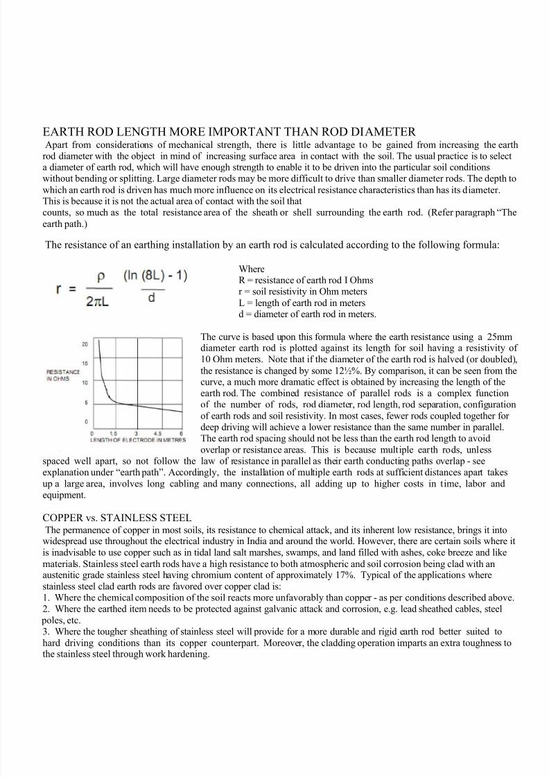
The resistance of an earthing installation by an earth rod is calculated according to the following formula:
WhereR = resistance of earth rod I Ohmsr = soil resistivity in Ohm meters
L = length of earth rod in metersd = diameter of earth rod in meters.
The curve is based upon this formula where the earth resistance using a 25mmdiameter earth rod is plotted against its length for soil having a resistivity of
10 Ohm meters. Note that if the diameter of the earth rod is halved (or doubled),
the resistance is changed by some 12½%. By comparison, it can be seen from thecurve, a much more dramatic effect is obtained by increasing the length of theearth rod. The combined resistance of parallel rods is a complex function
of the number of rods, rod diameter, rod length, rod separation, configurationof earth rods and soil resistivity. In most cases, fewer rods coupled together for deep driving will achieve a lower resistance than the same number in parallel.The earth rod spacing should not be less than the earth rod length to avoid
overlap or resistance areas. This is because multiple earth rods, unlessspaced well apart, so not follow the law of resistance in parallel as their earth conducting paths overlap - seeexplanation under “earth path”. Accordingly, the installation of multiple earth rods at sufficient distances apart takes
up a large area, involves long cabling and many connections, all adding up to higher costs in time, labor andequipment.
COPPER vs. STAINLESS STEEL
The permanence of copper in most soils, its resistance to chemical attack, and its inherent low resistance, brings it into
widespread use throughout the electrical industry in India and around the world. However, there are certain soils where itis inadvisable to use copper such as in tidal land salt marshes, swamps, and land filled with ashes, coke breeze and like
materials. Stainless steel earth rods have a high resistance to both atmospheric and soil corrosion being clad with anaustenitic grade stainless steel having chromium content of approximately 17%. Typical of the applications where
stainless steel clad earth rods are favored over copper clad is:1. Where the chemical composition of the soil reacts more unfavorably than copper - as per conditions described above.2. Where the earthed item needs to be protected against galvanic attack and corrosion, e.g. lead sheathed cables, steel
poles, etc.3. Where the tougher sheathing of stainless steel will provide for a more durable and rigid earth rod better suited to
hard driving conditions than its copper counterpart. Moreover, the cladding operation imparts an extra toughness tothe stainless steel through work hardening.
8/3/2019 Earthing a Brief Introduction
http://slidepdf.com/reader/full/earthing-a-brief-introduction 5/14
SAFETY DATA SHEET
GROUND IMPROVING MATERIAL SAFETY DATA SHEET
1. IDENTIFICATION OF THE SUBSTANCE
Product name: GROUND IMPROVING MATERIALProduct code: GIM & BFC
Use / description of product: Granular Solid.
2. COMPOSITION / INFORMATION ON INGREDIENTS
INGREDIANTS: BentoniteHydrous aluminum silicates
GraphiteConducting metal powdersBounding resins
NOTE: Ground fill material is enhanced, activated and chemically modified homogenous mixture
based upon bentonite made suitable for earthing purpose to increase the effectiveness of the
earthing system.
3. HAZARDS IDENTIFICATION
Main hazards: No significant hazard.Other hazards: Combustible. Exposure Limits (Dust): 10 mg/m3 total dust, 4 mg/m3 repairable dust
4. FIRST AID MEASURES (SYMPTOMS)
Skin contact: There may be mild irritation at the site of contact.Eye contact: There may be irritation and redness.Ingestion: It is unlikely that this substance will be swallowed due to its physical properties.
Inhalation: There may be irritation of the throat with a feeling of tightness in the chest.
4. FIRST AID MEASURES (ACTION)
Eye contact: Bathe the eye with running water for 5 minutes. Consult a doctor.Inhalation: Remove casualty from exposure ensuring one's own safety whilst doing so.
5. FIRE-FIGHTING MEASURES
Extinguishing media: Water spray, Alcohol or polymer foam, Dry chemical powder, Carbon dioxide
Exposure hazards: In combustion emits toxic fumes of carbon dioxide / carbon monoxide.
Protection of fire-fighters: Wear self-contained breathing apparatus.
8/3/2019 Earthing a Brief Introduction
http://slidepdf.com/reader/full/earthing-a-brief-introduction 6/14
SAFETY DATA SHEET
6. ACCIDENTAL RELEASE MEASURES
Personal precautions: Refer to section 8 of SDS for personal protection details. Do not create dust.Environmental precautions: Do not discharge into drains or rivers.
Clean-up procedures: Transfer to a suitable container. Refer to section 13 for suitable method of
disposal.
7. HANDLING AND STORAGE
Handling requirements: Ensure sufficient ventilation of the area. Avoid the formation or spread of dust in theair.
Storage conditions: Store in cool, well ventilated area.
8. EXPOSURE CONTROLS / PERSONAL PROTECTION
Occupational exposure limitsTWA (8 hr exposure limit): 4mg.m3 Res Dust
STEL (15 min exposure limit): 4mg.m3 Res DustEngineering measures: Ensure there is sufficient ventilation of the area.Respiratory protection: Respiratory protective device with particle filter.
Hand protection: Protective gloves.Eye protection: Safety glasses with side-shields.
Skin protection: Protective clothing with elasticized cuffs and closed neck.
9. PHYSICAL AND CHEMICAL PROPERTIES
State: Solid powder 75 meshColour: Light grey
Odor: Odorless
Solubility in water: InsolubleViscosity: Non-viscous
Relative density: 1890-1990 kg/m3
10. STABILITY AND REACTIVITY
Stability: Stable under normal conditions.Conditions to avoid: Sources of ignition.
Materials to avoid: Strong oxidizing agents.
Haz. Decomp. Products: In combustion emits toxic fumes of carbon dioxide / carbon monoxide.
11. TOXICOLOGICAL INFORMATION
Chronic toxicity: Danger of cumulative effects through inhalation.Routes of exposure: Refer to section 4 of SDS for routes of exposure and corresponding symptoms.

8/3/2019 Earthing a Brief Introduction
http://slidepdf.com/reader/full/earthing-a-brief-introduction 7/14
SAFETY DATA SHEET
12. ECOLOGICAL INFORMATION
Mobility: Non-volatile. Insoluble in water Heavier than water
Persistence and degradability: No data available.
Bio accumulative potential: No data available.Other adverse effects: Negligible eco toxicity.
13. DISPOSAL CONSIDERATIONS
Disposal operations: D1 Tipping above or underground (e.g. landfill, etc.).R4 Recycling/reclamation of other inorganic materials
Disposal of packaging: Dispose of as normal industrial waste.
NB: The user's attention is drawn to the possible existence of regional or national regulations regarding
disposal.
14. TRANSPORT INFORMATION
ADR / RIDIMDG / IMO
IATA / ICAO
15. REGULATORY INFORMATION
Hazard symbols: No significant hazard.Safety phrases: S22: Do not breathe dust.
S26: In case of contact with eyes, rinse immediately with plenty of water and seek medicaladvice.
S27: Take off immediately all contaminated clothing.
S36: Wear suitable protective clothing.
Note: The regulatory information given above only indicates the principal regulations specifically applicableto the product described in the safety data sheet. The user's attention is drawn to the possible existence of
additional provisions which complete these regulations. Refer to all applicable national, international and localregulations or provisions.
16. OTHER INFORMATION
Legal disclaimer: The above information is believed to be correct but does not purport to be all inclusiveand shall be used only as a guide. This company shall not be held liable for any damage resulting from handlingor from contact with the above product.
8/3/2019 Earthing a Brief Introduction
http://slidepdf.com/reader/full/earthing-a-brief-introduction 8/14
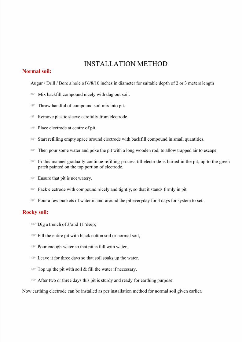
INSTALLATION METHODNormal soil:
Augur / Drill / Bore a hole of 6/8/10 inches in diameter for suitable depth of 2 or 3 meters length
☞ Mix backfill compound nicely with dug out soil.
☞ Throw handful of compound soil mix into pit.
☞ Remove plastic sleeve carefully from electrode.
☞ Place electrode at centre of pit.
☞ Start refilling empty space around electrode with backfill compound in small quantities.
☞ Then pour some water and poke the pit with a long wooden rod, to allow trapped air to escape.
☞ In this manner gradually continue refilling process till electrode is buried in the pit, up to the green patch painted on the top portion of electrode.
☞ Ensure that pit is not watery.
☞ Pack electrode with compound nicely and tightly, so that it stands firmly in pit.
☞ Pour a few buckets of water in and around the pit everyday for 3 days for system to set.
Rocky soil:
☞ Dig a trench of 3’and 11’deep;
☞ Fill the entire pit with black cotton soil or normal soil,
☞ Pour enough water so that pit is full with water,
☞ Leave it for three days so that soil soaks up the water.
☞ Top up the pit with soil & fill the water if necessary.
☞ After two or three days this pit is sturdy and ready for earthing purpose.
Now earthing electrode can be installed as per installation method for normal soil given earlier.
8/3/2019 Earthing a Brief Introduction
http://slidepdf.com/reader/full/earthing-a-brief-introduction 9/14
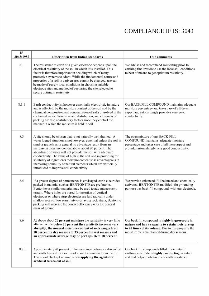
COMPLIANCE IF IS: 3043
IS3043:1987 Description from Indian standards Our comments
8.1 The resistance to earth of a given electrode depends upon the
electrical resistivity of the soil in which it is installed. This
factor is therefore important in deciding which of many
protective systems to adopt. While the fundamental nature and properties of a soil in a given area cannot be changed, use can
be made of purely local conditions in choosing suitable
electrode sites and method of preparing the site selected to
secure optimum resistivity.
We advise and recommend soil testing prior to
earthing finalization to use the local soil conditions
to best of means to get optimum resistivity.
8.1.1 Earth conductivity is, however essentially electrolytic in natureand is affected, by the moisture content of the soil and by the
chemical composition and concentration of salts dissolved in the
contained water. Grain size and distribution, and closeness of packing are also contributory factors since they control the
manner in which the moisture is held in soil.
Our BACK FILL COMPOUND maintains adequatemoisture percentage and takes care of all these
aspect and astonishingly provides very good
conductivity.
8.3 A site should be chosen that is not naturally well drained. A
water logged situation is not however, essential unless the soil is
sand or gravels as in general no advantage result from anincrease in moisture content above about 20 percent. The
abundance of water will not provide the soil with adequate
conductivity. The value of high in the soil and in providing for solubility of ingredients moisture content so is advantageous in
increasing solubility of natural elements which are artificially
introduced to improve soil conductivity.
The even mixture of our BACK FILL
COMPOUND maintains adequate moisture
percentage and takes care of all these aspect and provides astonishingly very good conductivity.
8.5 If a greater degree of permanence is envisaged, earth electrodes packed in material such as BENTONITE are preferable.
Bentonite or similar material may be used to advantage rocky
terrain. Where holes are bored for insertion of vertical
electrodes or where strip electrodes are laid radically under shallow areas of low resistivity overlaying rock strata, Bentonite
packing will increase the contact efficiency with the general
mass of ground.
We provide enhanced, PH balanced and chemicallyactivated BENTONITE modified for grounding
purpose , as back fill compound with our electrode.
8.6 At above about 20 percent moisture the resistivity is very littleaffected while below 20 percent the resistivity increase very
abruptly, the normal moisture content of soils ranges from
10 percent in dry seasons to 35 percent in wet seasons andan approximate average may be perhaps 16 to 18 percent.
Our back fill compound is highly hygroscopic in
nature and has a capacity to retain moisture upto 20 times of its volume. Due to this property the
moisture % is maintained during dry seasons.
8.8.1 Approximately 90 present of the resistance between a driven rod
and earth lies within a radius of about two meters from the rod.
This should be kept in mind when applying the agents for
artificial treatment of soil.
Our back fill compounds filled in vicinity of
earthing electrode is highly conducting in nature
and that helps to obtain lower earth resistance.
8/3/2019 Earthing a Brief Introduction
http://slidepdf.com/reader/full/earthing-a-brief-introduction 10/14
COMPLIANCE IF IS: 3043
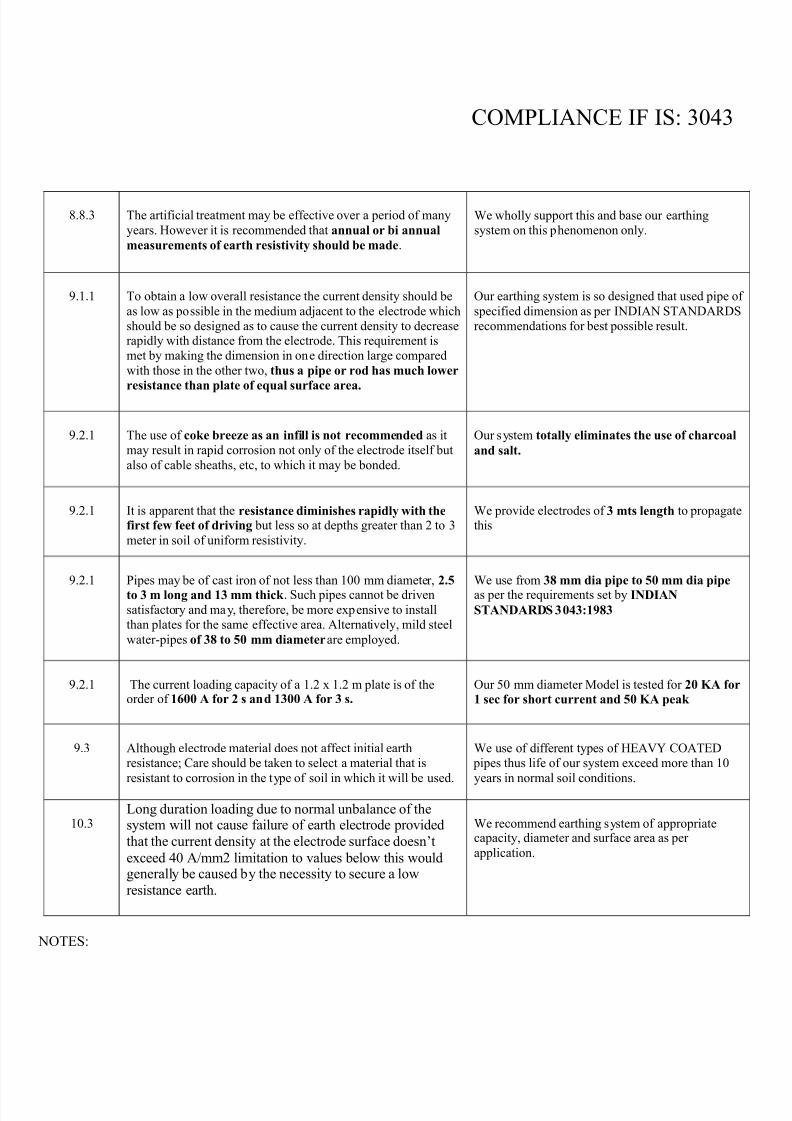
8.8.3 The artificial treatment may be effective over a period of many
years. However it is recommended that annual or bi annual
measurements of earth resistivity should be made.
We wholly support this and base our earthing
system on this phenomenon only.
9.1.1 To obtain a low overall resistance the current density should be
as low as possible in the medium adjacent to the electrode which
should be so designed as to cause the current density to decreaserapidly with distance from the electrode. This requirement is
met by making the dimension in one direction large compared
with those in the other two, thus a pipe or rod has much lower
resistance than plate of equal surface area.
Our earthing system is so designed that used pipe of
specified dimension as per INDIAN STANDARDS
recommendations for best possible result.
9.2.1 The use of coke breeze as an infill is not recommended as it
may result in rapid corrosion not only of the electrode itself but
also of cable sheaths, etc, to which it may be bonded.
Our system totally eliminates the use of charcoal
and salt.
9.2.1 It is apparent that the resistance diminishes rapidly with the first few feet of driving but less so at depths greater than 2 to 3
meter in soil of uniform resistivity.
We provide electrodes of 3 mts length to propagatethis
9.2.1 Pipes may be of cast iron of not less than 100 mm diameter, 2.5
to 3 m long and 13 mm thick . Such pipes cannot be driven
satisfactory and may, therefore, be more expensive to install
than plates for the same effective area. Alternatively, mild steel
water-pipes of 38 to 50 mm diameter are employed.
We use from 38 mm dia pipe to 50 mm dia pipe as per the requirements set by INDIAN
STANDARDS 3043:1983
9.2.1 The current loading capacity of a 1.2 x 1.2 m plate is of theorder of 1600 A for 2 s and 1300 A for 3 s.
Our 50 mm diameter Model is tested for 20 KA for
1 sec for short current and 50 KA peak
9.3 Although electrode material does not affect initial earth
resistance; Care should be taken to select a material that is
resistant to corrosion in the type of soil in which it will be used.
We use of different types of HEAVY COATED
pipes thus life of our system exceed more than 10
years in normal soil conditions.
10.3Long duration loading due to normal unbalance of thesystem will not cause failure of earth electrode provided
that the current density at the electrode surface doesn’t
exceed 40 A/mm2 limitation to values below this wouldgenerally be caused by the necessity to secure a low
resistance earth.
We recommend earthing system of appropriatecapacity, diameter and surface area as per
application.
NOTES:
8/3/2019 Earthing a Brief Introduction
http://slidepdf.com/reader/full/earthing-a-brief-introduction 11/14
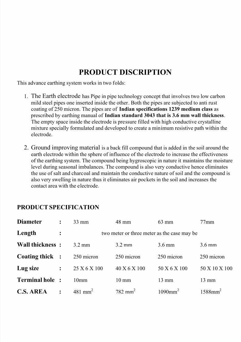
PRODUCT DISCRIPTION
This advance earthing system works in two folds:
1. The Earth electrode has Pipe in pipe technology concept that involves two low carbon
mild steel pipes one inserted inside the other. Both the pipes are subjected to anti rust
coating of 250 micron. The pipes are of Indian specifications 1239 medium class as
prescribed by earthing manual of Indian standard 3043 that is 3.6 mm wall thickness.
The empty space inside the electrode is pressure filled with high conductive crystallinemixture specially formulated and developed to create a minimum resistive path within the
electrode.
2. Ground improving material is a back fill compound that is added in the soil around the
earth electrode within the sphere of influence of the electrode to increase the effectiveness
of the earthing system. The compound being hygroscopic in nature it maintains the moisture
level during seasonal imbalances. The compound is also very conductive hence eliminates
the use of salt and charcoal and maintain the conductive nature of soil and the compound is
also very swelling in nature thus it eliminates air pockets in the soil and increases thecontact area with the electrode.
PRODUCT SPECIFICATION
Diameter : 33 mm 48 mm 63 mm 77mm
Length : two meter or three meter as the case may be
Wall thickness : 3.2 mm 3.2 mm 3.6 mm 3.6 mm
Coating thick : 250 micron 250 micron 250 micron 250 micron
Lug size : 25 X 6 X 100 40 X 6 X 100 50 X 6 X 100 50 X 10 X 100
Terminal hole : 10mm 10 mm 13 mm 13 mm
C.S. AREA : 481 mm2 782 mm
2 1090mm
2 1588mm
2
8/3/2019 Earthing a Brief Introduction
http://slidepdf.com/reader/full/earthing-a-brief-introduction 12/14
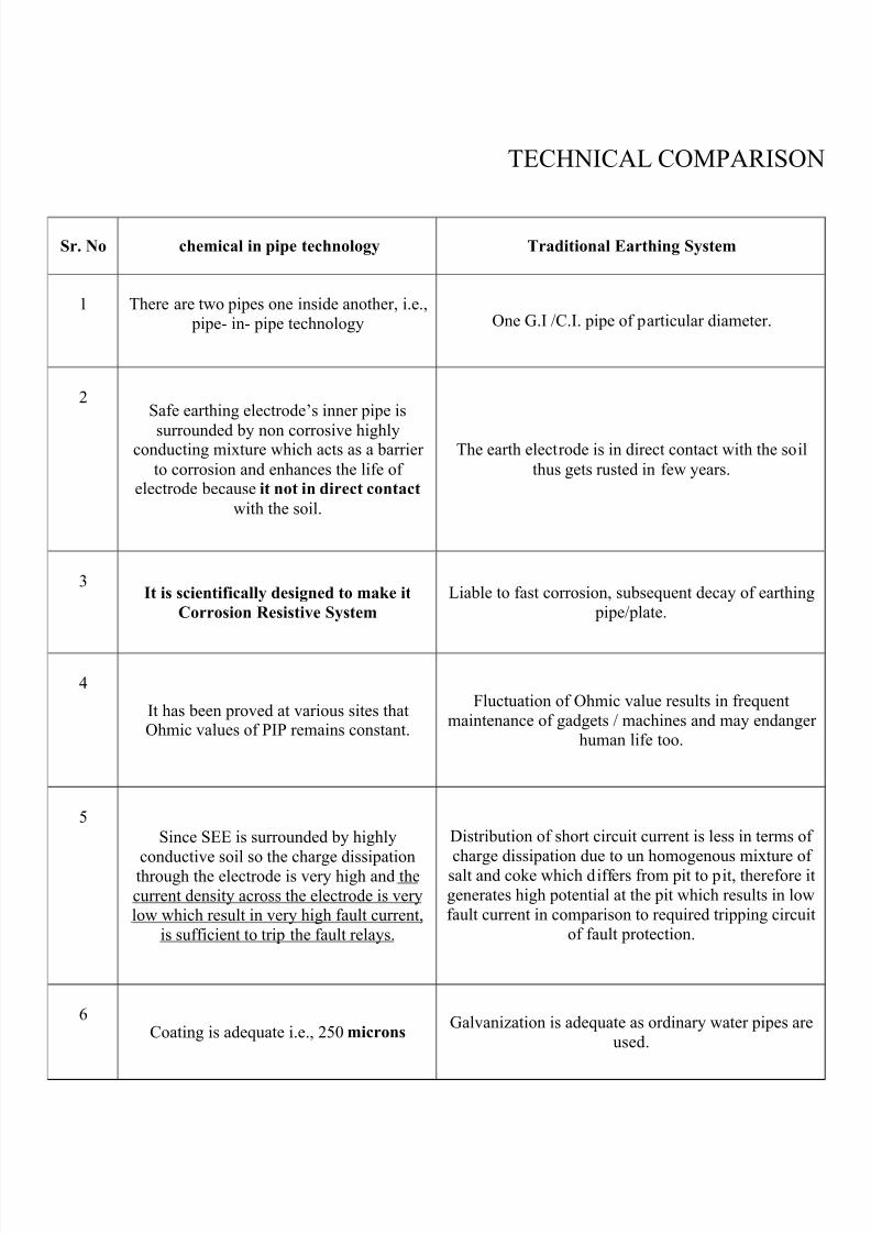
TECHNICAL COMPARISON
Sr. No chemical in pipe technology Traditional Earthing System
1 There are two pipes one inside another, i.e.,
pipe- in- pipe technology One G.I /C.I. pipe of particular diameter.
2Safe earthing electrode’s inner pipe is
surrounded by non corrosive highlyconducting mixture which acts as a barrier
to corrosion and enhances the life of electrode because it not in direct contact
with the soil.
The earth electrode is in direct contact with the soil
thus gets rusted in few years.
3It is scientifically designed to make it
Corrosion Resistive System
Liable to fast corrosion, subsequent decay of earthing
pipe/plate.
4
It has been proved at various sites thatOhmic values of PIP remains constant.
Fluctuation of Ohmic value results in frequent
maintenance of gadgets / machines and may endanger human life too.
5
Since SEE is surrounded by highly
conductive soil so the charge dissipationthrough the electrode is very high and the
current density across the electrode is verylow which result in very high fault current,
is sufficient to trip the fault relays.
Distribution of short circuit current is less in terms of
charge dissipation due to un homogenous mixture of salt and coke which differs from pit to pit, therefore it
generates high potential at the pit which results in low
fault current in comparison to required tripping circuit
of fault protection.
6Coating is adequate i.e., 250 microns
Galvanization is adequate as ordinary water pipes are
used.
8/3/2019 Earthing a Brief Introduction
http://slidepdf.com/reader/full/earthing-a-brief-introduction 13/14
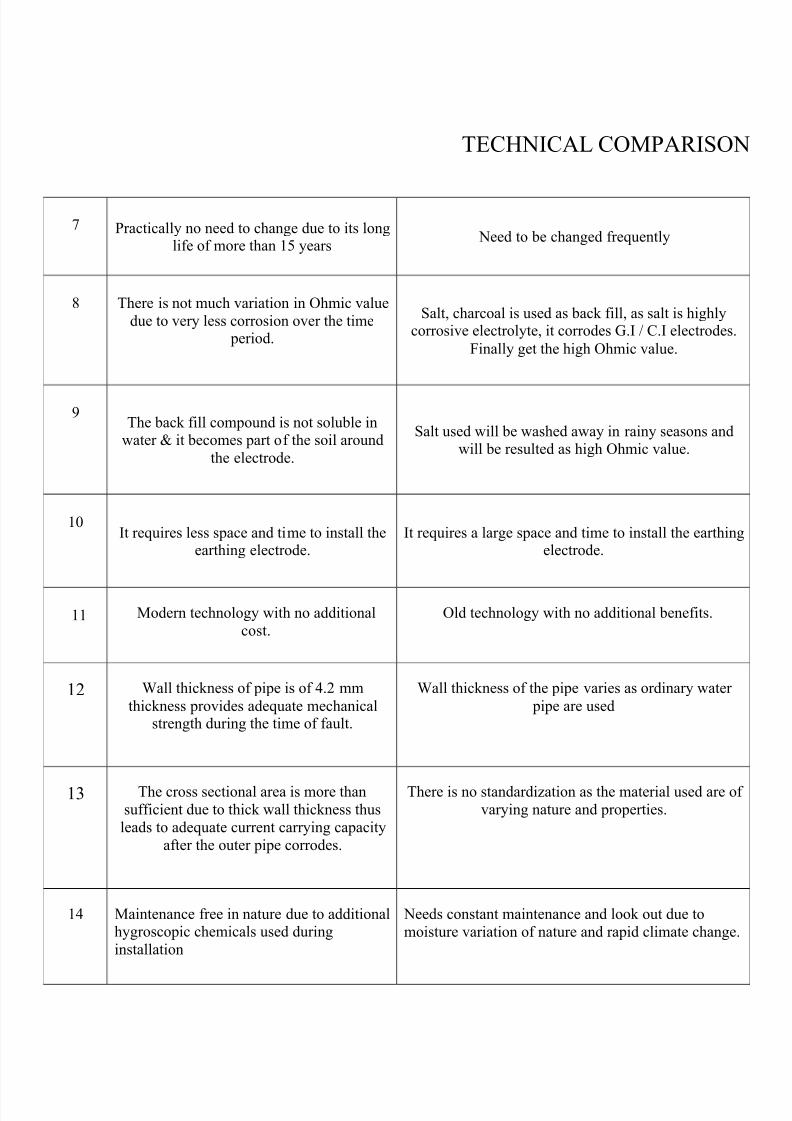
TECHNICAL COMPARISON
7 Practically no need to change due to its longlife of more than 15 years
Need to be changed frequently
8 There is not much variation in Ohmic value
due to very less corrosion over the time period.
Salt, charcoal is used as back fill, as salt is highlycorrosive electrolyte, it corrodes G.I / C.I electrodes.
Finally get the high Ohmic value.
9The back fill compound is not soluble in
water & it becomes part of the soil around
the electrode.
Salt used will be washed away in rainy seasons andwill be resulted as high Ohmic value.
10It requires less space and time to install the
earthing electrode.It requires a large space and time to install the earthing
electrode.
11 Modern technology with no additional
cost.
Old technology with no additional benefits.
12 Wall thickness of pipe is of 4.2 mm
thickness provides adequate mechanicalstrength during the time of fault.
Wall thickness of the pipe varies as ordinary water
pipe are used
13 The cross sectional area is more than
sufficient due to thick wall thickness thus
leads to adequate current carrying capacity
after the outer pipe corrodes.
There is no standardization as the material used are of
varying nature and properties.
14 Maintenance free in nature due to additionalhygroscopic chemicals used during
installation
Needs constant maintenance and look out due to
moisture variation of nature and rapid climate change.
8/3/2019 Earthing a Brief Introduction
http://slidepdf.com/reader/full/earthing-a-brief-introduction 14/14
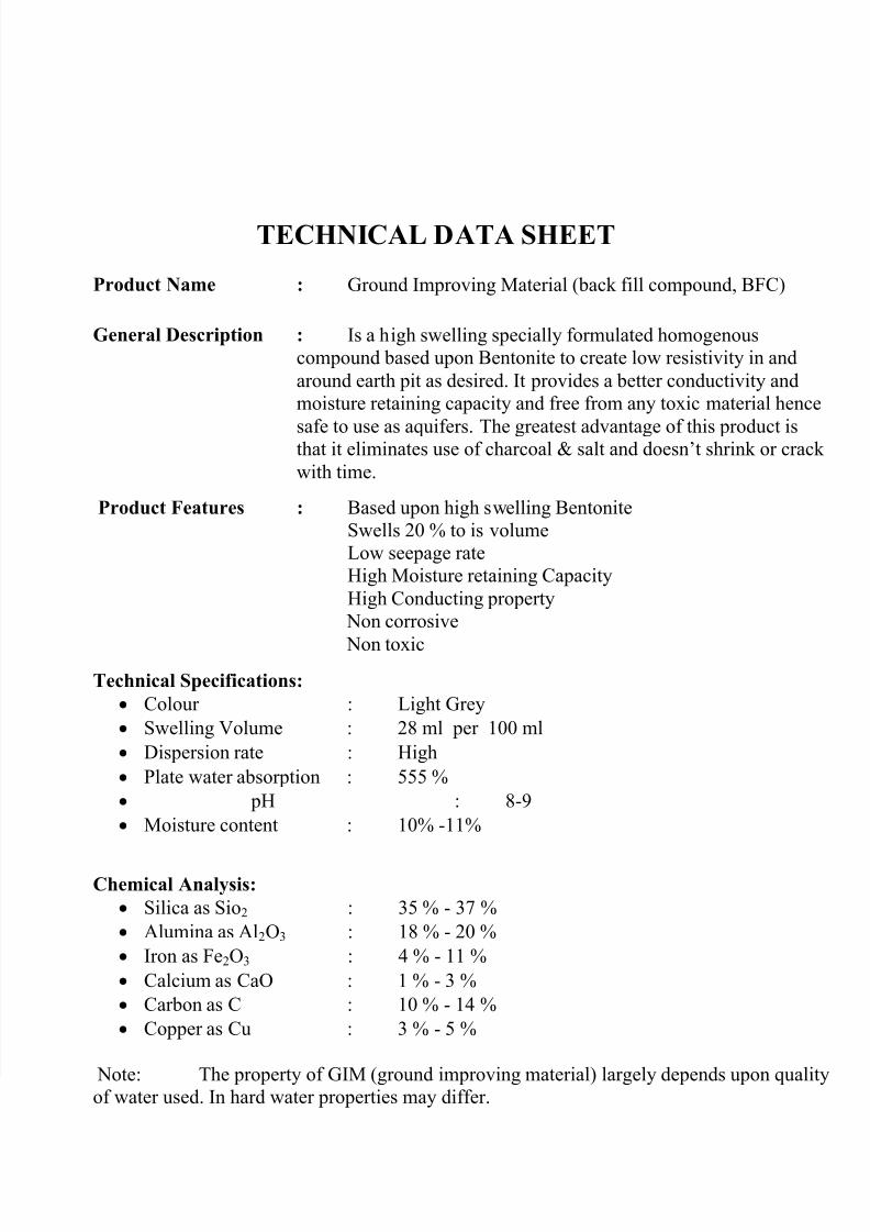
TECHNICAL DATA SHEET
Product Name : Ground Improving Material (back fill compound, BFC)
General Description : Is a high swelling specially formulated homogenous
compound based upon Bentonite to create low resistivity in and
around earth pit as desired. It provides a better conductivity and
moisture retaining capacity and free from any toxic material hence
safe to use as aquifers. The greatest advantage of this product isthat it eliminates use of charcoal & salt and doesn’t shrink or crack
with time.
Product Features : Based upon high swelling Bentonite
Swells 20 % to is volume
Low seepage rate
High Moisture retaining Capacity
High Conducting property
Non corrosive
Non toxic
Technical Specifications:
Colour : Light Grey
Swelling Volume : 28 ml per 100 ml
Dispersion rate : High
Plate water absorption : 555 %
pH : 8-9
Moisture content : 10% -11%
Chemical Analysis:
Silica as Sio2 : 35 % - 37 %
Alumina as Al2O3 : 18 % - 20 %
Iron as Fe2O3 : 4 % - 11 %
Calcium as CaO : 1 % - 3 %
Carbon as C : 10 % - 14 %
Copper as Cu : 3 % - 5 %
Note: The property of GIM (ground improving material) largely depends upon qualityof water used. In hard water properties may differ.