Embed Size (px)
DESCRIPTION
tutorial minex 6.3
Citation preview


Copyright © 2013 Dassault Systèmes GEOVIA Inc.
All rights reserved. Dassault Systèmes GEOVIA Inc. publishes this documentation for the sole use of
GEOVIA product licensees.
Without written permission, you may not sell, reproduce, store in a retrieval system, or transmit
any part of this documentation. For such permission, or to obtain extra copies please contact your
local GEOVIA office, or visit www.3ds.com/GEOVIA.
This software and documentation is proprietary to Dassault Systèmes GEOVIA Inc. and, except
where expressly provided otherwise, does not form part of any contract. Changes may bemade in
products or services at any timewithout notice.
While every precaution has been taken in the preparation of this manual, neither the authors nor
GEOVIA assumes responsibility for errors or omissions. Neither will be held liable for any damages
caused or alleged to be caused from the use of the information contained herein.
Dassault Systèmes GEOVIA Inc. offers complete 3D software tools that let you create, simulate,
publish, and manage your data.
GEOVIA, the GEOVIA logo, combinations thereof, and GEMS, Surpac, Minex, MineSched, Whittle,
PCBC, InSite, and Hub are either trademarks or registered trademarks of Dassault Systèmes or its
subsidiaries in the US and/or other countries.
Product
GEOVIAMinex™ 6.3
Last modified: Thursday, 29 August 2013
Earth Works tutorial

Table of Contents
About this document 5
Overview 5
Requirements 5
Objectives 5
Workflow 6
Document conventions 7
Typographical conventions 7
Keyboard conventions 7
Menu conventions 7
Mouse conventions 8
Form elements 8
Setup for this tutorial 11
Tutorial data 11
Activity: Install the data set 11
Data set location 11
Activity: Back up the data set 11
Create a Minex project 12
Activity: Create a Minex project 12
Designing a dump 14
Workflow 14
Generating a max spoil pile 14
Activity: Generate a maximum spoil pile 15
Activity: Determine the elevation of the dump 19
Activity: Create a bench list for the dump 21
Activity: Create a dump 22
Activity: Compute the dump surface 25
Activity: Calculate the dump volume 26
Designing a multi-bench Max Spoil 28
Activity: Create a multi-bench max spoil 28
Designing a drag spoil 33
Activity: Create drag spoil pile strings 33
Activity: Generate drag spoil piles 37
Creating haul roads 41

Activity: Create a road centre line 41
Activity: Create a haul road 42
Regrading spoil piles 50
Activity: Compute spoil regrade 50
Activity: Display regraded spoil grids 54
Activity: Report on regraded spoil grids 56
Rehabilitating a surface 58
Workflow 58
Section strings 58
Activity: Digitise a section string 59
Activity: Create a template string and compute cut/fill 61
Summary 67

About this document
About this document
OverviewThis tutorial is designed to give you an overview of the EarthWorks and Spoil Regrade functions of
Minex. You use these tools to create surfaces for spoil piles, create haul roads, regrade spoil piles,
and rehabilitate surfaces.
This tutorial uses a data set that is copied to your computer when Minex is installed.
When the software has been installed, more detailed information is available in theMinex Help,
which you can open from theHelpmenu. You can also contact your local GEOVIA support office for
training.
RequirementsBefore proceeding with this tutorial, you will need:
l a good understanding of basic Minex concepts
l Minex 6.3 or later installed
l the EarthWorks data set
l a licence for the Open Pit Earth Works module and Spoil Reshaper module
If you accept the default settings when you first install Minex, the data sets are installed. If you chose
not to install the data sets, refer to the Set up for this tutorial section of this document.
ObjectivesAfter working through this tutorial, you will be able to:
l design a dump using themax spoil tool
l design a dump using the drag spoil tool
l create a haul road centre line
l create a haul road that cuts into a dump
l regrade a spoil pile
l rehabilitate a surface:
l create a cross section
l edit the cross section to create a slope
l cut and fill the slope
l create an optimised cut/fill surface
GEOVIA Minex™ 6.3 Page 5 of 67 Earth Works tutorial
Workflow
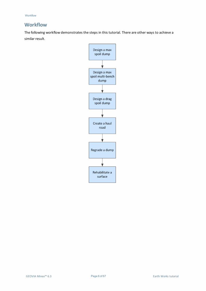
WorkflowThe following workflow demonstrates the steps in this tutorial. There are other ways to achieve a
similar result.
GEOVIA Minex™ 6.3 Page 6 of 67 Earth Works tutorial
Document conventions Typographical conventions
Document conventionsTypographical conventionsSome text in this guide has special formatting to help you identify it as part of a particular element of
information. The following table describes the different text formats and their meanings.
Text format Meaning
<Bold Italic>
Text or data that varies with each input is shown in bold italic font and enclosed in angle brackets.Some examples are installation directories, dates, names, and passwords. When you substitute thetext for the variable, do not include the brackets. For example: <password> requires you tosubstitute a password in place of ‘<password>’.
ItalicA word or phrase to which the author wants to give emphasis. For example: youmust select anitem from the list to continue.
Bold
This font style indicates one of the following:
l A file name, path, or URL.
l Strongly emphasised text. For example, “It is very important to save the data […]”.
l Text that a procedure has instructed you to type.
l A menu option, tab, button, check box, list, option button, text box, or icon.
For example: Save the file as pit1.str.
Keyboard conventionsKey combination Meaning
<key>+<key>Press and hold the first key, then press the second key. For example: CTRL+Z means pressand hold the CTRL key, then press Z.
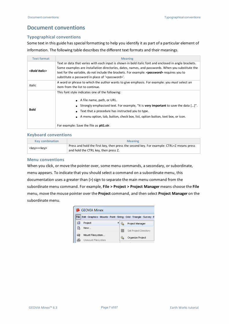
Menu conventionsWhen you click, or move the pointer over, somemenu commands, a secondary, or subordinate,
menu appears. To indicate that you should select a command on a subordinatemenu, this
documentation uses a greater than (>) sign to separate themain menu command from the
subordinatemenu command. For example, File > Project > Project Managermeans choose the File
menu, move themouse pointer over the Project command, and then select Project Manager on the
subordinatemenu.
GEOVIA Minex™ 6.3 Page 7 of 67 Earth Works tutorial
Document conventions Mouse conventions
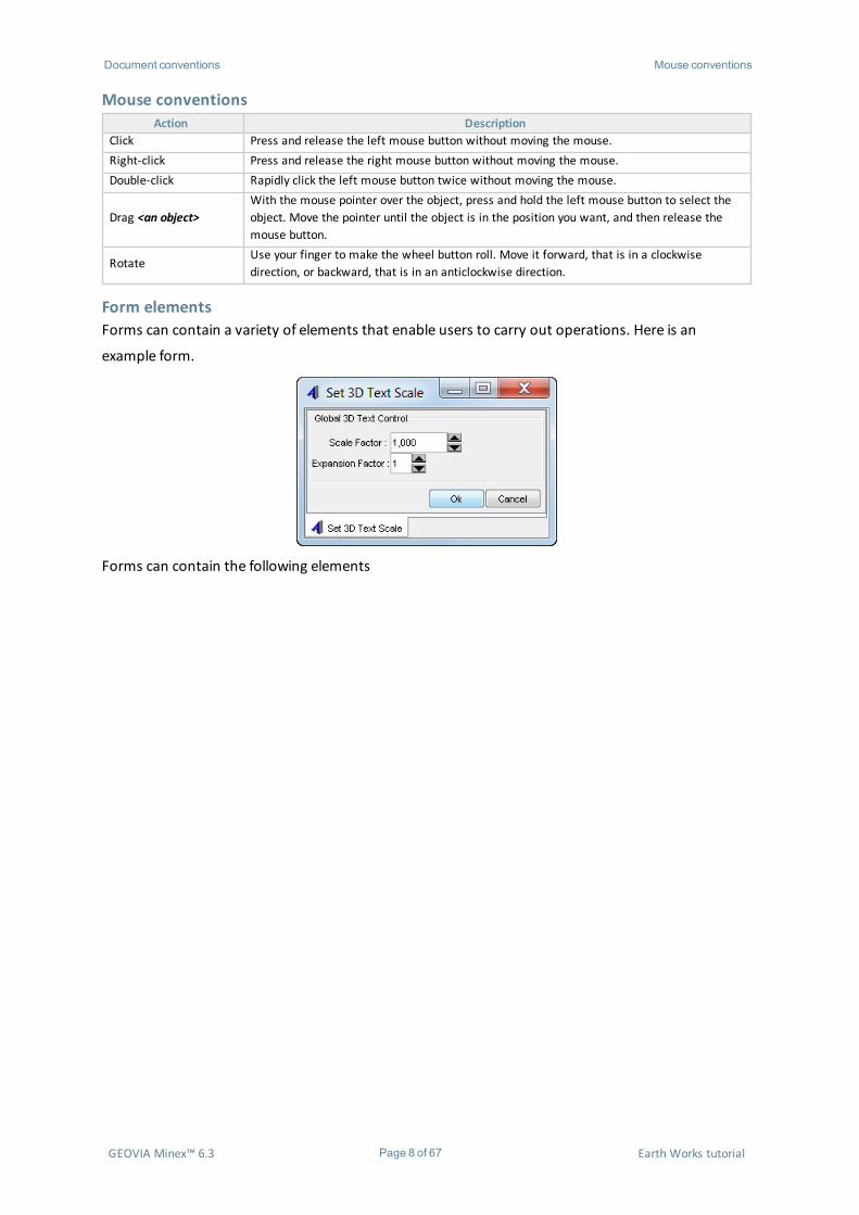
Mouse conventionsAction Description
Click Press and release the left mouse button without moving the mouse.Right-click Press and release the right mouse button without moving the mouse.Double-click Rapidly click the left mouse button twice without moving the mouse.
Drag <an object>With the mouse pointer over the object, press and hold the left mouse button to select theobject. Move the pointer until the object is in the position you want, and then release themouse button.
RotateUse your finger to make the wheel button roll. Move it forward, that is in a clockwisedirection, or backward, that is in an anticlockwise direction.
Form elementsForms can contain a variety of elements that enable users to carry out operations. Here is an
example form.
Forms can contain the following elements
GEOVIA Minex™ 6.3 Page 8 of 67 Earth Works tutorial
Document conventions Form elements
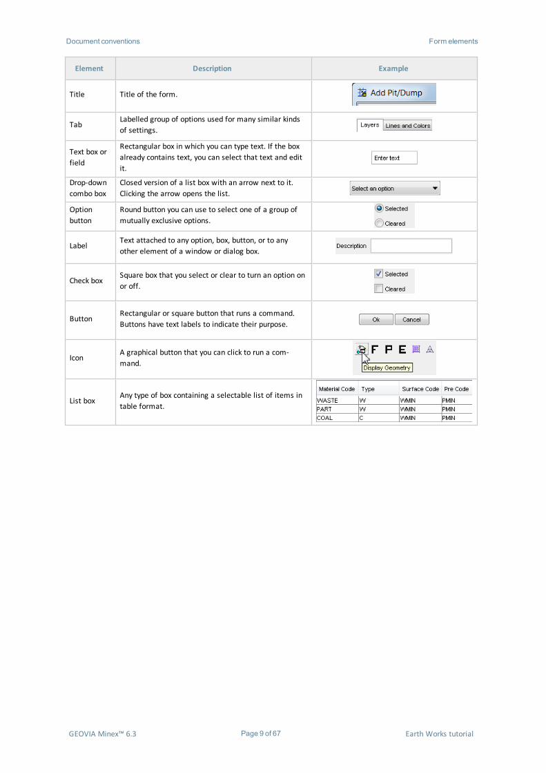
Element Description Example
Title Title of the form.
TabLabelled group of options used for many similar kindsof settings.
Text box orfield
Rectangular box in which you can type text. If the boxalready contains text, you can select that text and editit.
Drop-downcombo box
Closed version of a list box with an arrow next to it.Clicking the arrow opens the list.
Optionbutton
Round button you can use to select one of a group ofmutually exclusive options.
LabelText attached to any option, box, button, or to anyother element of a window or dialog box.
Check boxSquare box that you select or clear to turn an option onor off.
ButtonRectangular or square button that runs a command.Buttons have text labels to indicate their purpose.
IconA graphical button that you can click to run a com-mand.
List boxAny type of box containing a selectable list of items intable format.
GEOVIA Minex™ 6.3 Page 9 of 67 Earth Works tutorial
Document conventions Form elements
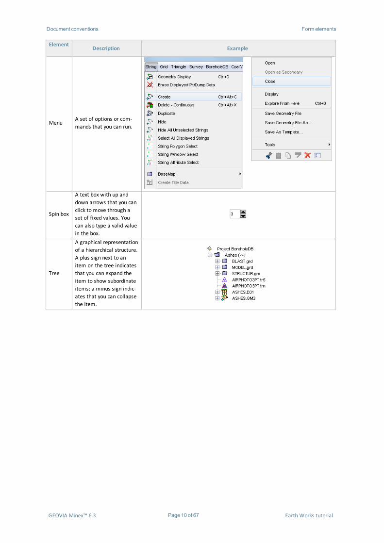
ElementDescription Example
MenuA set of options or com-mands that you can run.
Spin box
A text box with up anddown arrows that you canclick to move through aset of fixed values. Youcan also type a valid valuein the box.
Tree
A graphical representationof a hierarchical structure.A plus sign next to anitem on the tree indicatesthat you can expand theitem to show subordinateitems; a minus sign indic-ates that you can collapsethe item.
GEOVIA Minex™ 6.3 Page 10 of 67 Earth Works tutorial
Setup for this tutorial Activity: Install the data set
Setup for this tutorial
Tutorial dataWhen you install Minex and accept the default installation settings, the tutorial data is installed on
your machine. If you choose not to install the tutorial data sets when installing Minex, you can install
them separately.
Activity: Install the data set
1. Double-click theMinexInstallation.msi file on the installation CD.2. At theWelcomemessage, click Next.3. SelectModify, and click Next.
Minexdisplays the Custom Setup options.
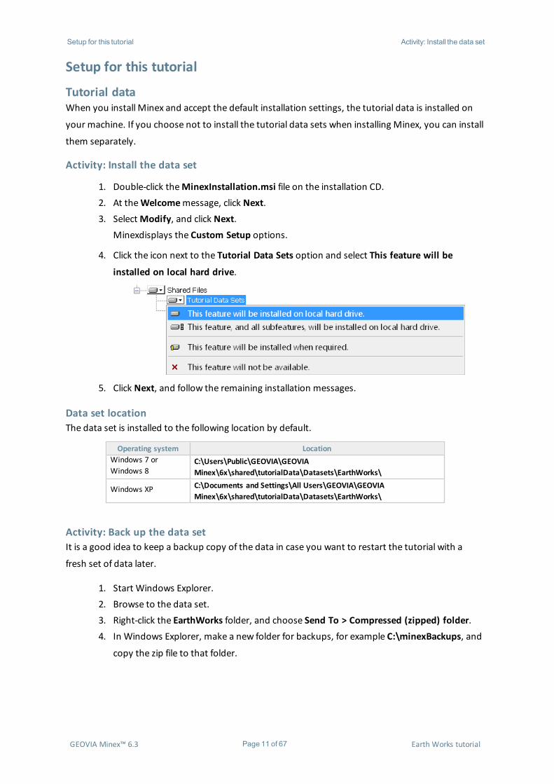
4. Click the icon next to the Tutorial Data Sets option and select This feature will be
installed on local hard drive.
5. Click Next, and follow the remaining installation messages.
Data set locationThe data set is installed to the following location by default.
Operating system LocationWindows 7 orWindows 8
C:\Users\Public\GEOVIA\GEOVIAMinex\6x\shared\tutorialData\Datasets\EarthWorks\
Windows XP C:\Documents and Settings\All Users\GEOVIA\GEOVIAMinex\6x\shared\tutorialData\Datasets\EarthWorks\
Activity: Back up the data setIt is a good idea to keep a backup copy of the data in case you want to restart the tutorial with a
fresh set of data later.
1. Start Windows Explorer.2. Browse to the data set.3. Right-click the EarthWorks folder, and choose Send To > Compressed (zipped) folder.4. In Windows Explorer, make a new folder for backups, for example C:\minexBackups, and
copy the zip file to that folder.
GEOVIA Minex™ 6.3 Page 11 of 67 Earth Works tutorial
Setup for this tutorial Activity: Create aMinexproject
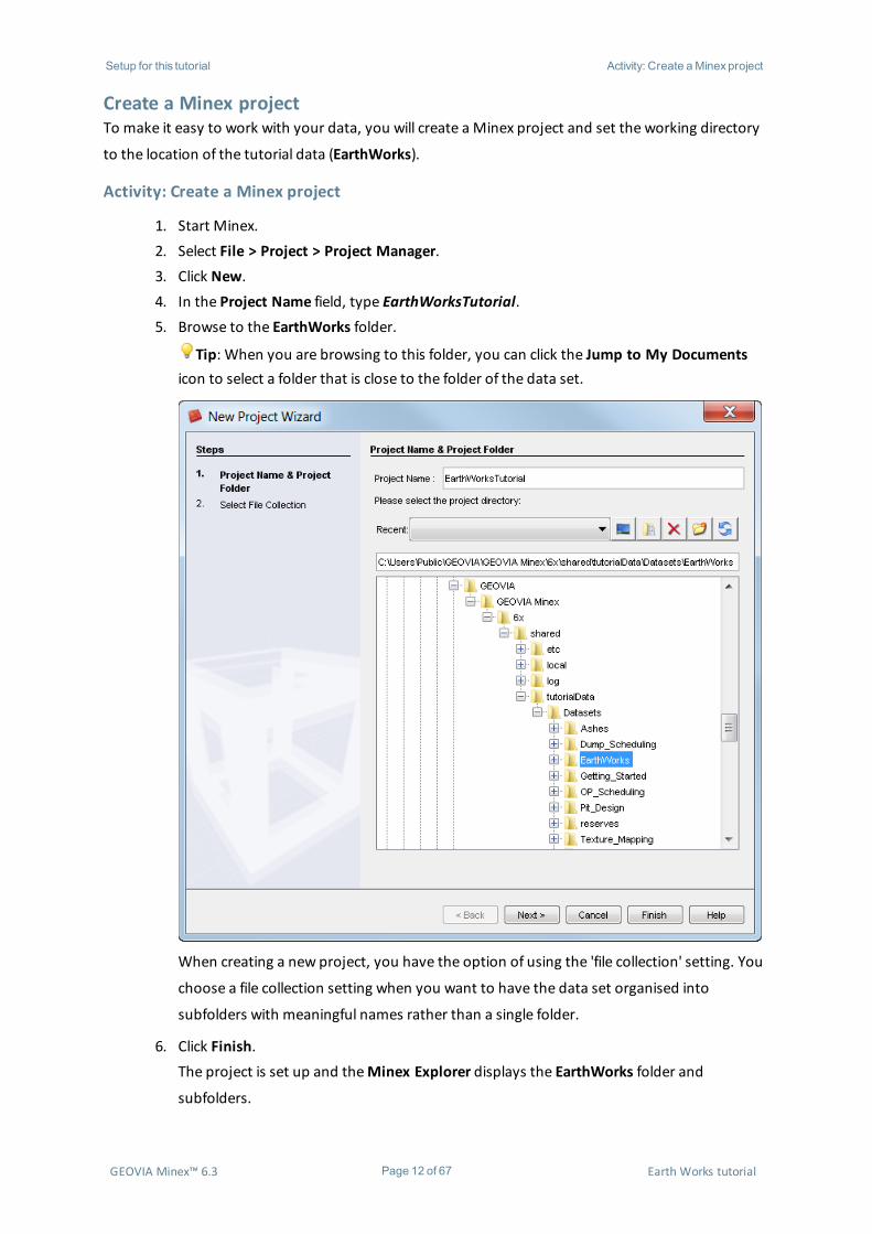
Create a Minex projectTo make it easy to work with your data, you will create a Minex project and set the working directory
to the location of the tutorial data (EarthWorks).
Activity: Create a Minex project
1. Start Minex.2. Select File > Project > Project Manager.3. Click New.4. In the Project Name field, type EarthWorksTutorial.5. Browse to the EarthWorks folder.
Tip: When you are browsing to this folder, you can click the Jump to My Documentsicon to select a folder that is close to the folder of the data set.
When creating a new project, you have the option of using the 'file collection' setting. You
choose a file collection setting when you want to have the data set organised into
subfolders with meaningful names rather than a single folder.
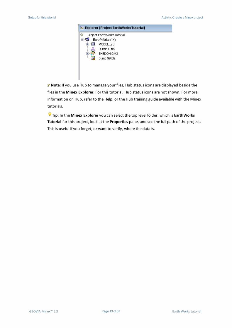
6. Click Finish.The project is set up and theMinex Explorer displays the EarthWorks folder and
subfolders.
GEOVIA Minex™ 6.3 Page 12 of 67 Earth Works tutorial
Setup for this tutorial Activity: Create aMinexproject
Note: If you use Hub to manage your files, Hub status icons are displayed beside the
files in theMinex Explorer. For this tutorial, Hub status icons are not shown. For more
information on Hub, refer to the Help, or the Hub training guide available with theMinex
tutorials.
Tip: In theMinex Explorer you can select the top level folder, which is EarthWorksTutorial for this project, look at the Properties pane, and see the full path of the project.
This is useful if you forget, or want to verify, where the data is.
GEOVIA Minex™ 6.3 Page 13 of 67 Earth Works tutorial

Designing a dump Activity: Create aMinexproject
Designing a dump
WorkflowThe following workflow demonstrates the steps in this section of the tutorial. There are other ways to
achieve a similar result.
Generating a max spoil pileYou use theMax Spoil function to:
l create spoil piles or dumps on a surface:
l For an in-pit dump, the surface could be the pit at a given time.
l For an out-of-pit dump, the surface could be the original topography.
l create spoil piles with different spoil angles on different segments of the dump
l create surfaces of prospective dumps
l create surfaces that give a visual representation of the progressions of a dump over the
life of a mine
l report volumes and represent different periods using different surface colours
Note: You cannot use theMax Spoil tool to create dumps with ramps, as the tool works by
building a dump up from a toe polygon. To create dumps with ramps, use the Pit Design tool.
GEOVIA Minex™ 6.3 Page 14 of 67 Earth Works tutorial
Designing a dump Activity: Generate amaximum spoil pile
Activity: Generate a maximum spoil pile
1. Open the geometry file THEDON.GM3.2. In theMinex Explorer, expand theMODEL grid folder, right-click TOPS, and chooseDis-
play and Open.
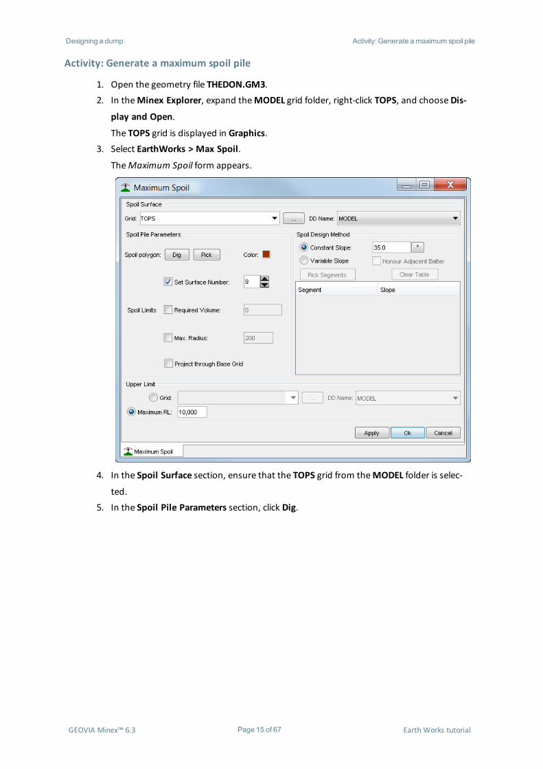
The TOPS grid is displayed in Graphics.3. Select EarthWorks > Max Spoil.
TheMaximum Spoil form appears.
4. In the Spoil Surface section, ensure that the TOPS grid from theMODEL folder is selec-
ted.5. In the Spoil Pile Parameters section, click Dig.
GEOVIA Minex™ 6.3 Page 15 of 67 Earth Works tutorial
Designing a dump Activity: Generate amaximum spoil pile
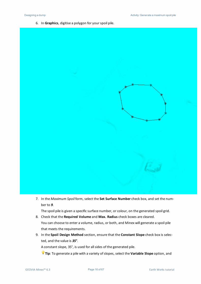
6. In Graphics, digitise a polygon for your spoil pile.
7. In theMaximum Spoil form, select the Set Surface Number check box, and set the num-
ber to 9.
The spoil pile is given a specific surface number, or colour, on the generated spoil grid.8. Check that the Required Volume andMax. Radius check boxes are cleared.
You can choose to enter a volume, radius, or both, and Minex will generate a spoil pile
that meets the requirements.9. In the Spoil Design Method section, ensure that the Constant Slope check box is selec-
ted, and the value is 35°.
A constant slope, 35°, is used for all sides of the generated pile.
Tip: To generate a pile with a variety of slopes, select the Variable Slope option, and
GEOVIA Minex™ 6.3 Page 16 of 67 Earth Works tutorial

Designing a dump Activity: Generate amaximum spoil pile
click Pick Segments. You can then select a segment of the spoil polygon, and assign a
slope value to each segment.10. Ensure that theGrid option is cleared.
If theGrid option is selected, the spoil pile is cut off where it intersects the selected grid.11. In theUpper Limit section, ensure that theMaximum RL option is selected.12. Click Apply.
Minex generates a preview of the resulting spoil pile in Graphics, and the spoil volume is
shown in theOutput Window.
GEOVIA Minex™ 6.3 Page 17 of 67 Earth Works tutorial

Designing a dump Activity: Generate amaximum spoil pile
Tip: You can redefine the parameters and click Apply again to generate a new pile pre-view and report.
13. When you are happy with the spoil pile, on theMaximum Spoil form, click Ok to save the
grid.
GEOVIA Minex™ 6.3 Page 18 of 67 Earth Works tutorial
Designing a dump Activity: Determine the elevation of the dump
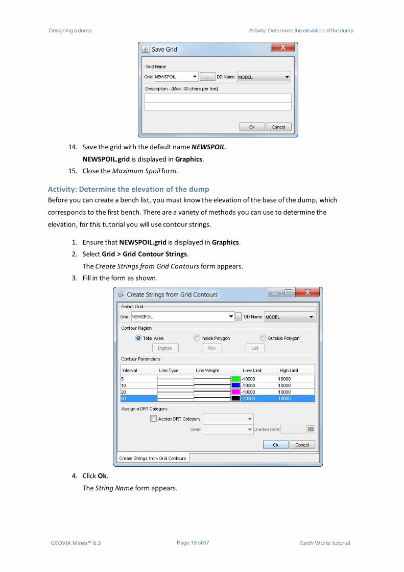
14. Save the grid with the default nameNEWSPOIL.
NEWSPOIL.grid is displayed in Graphics.15. Close theMaximum Spoil form.
Activity: Determine the elevation of the dumpBefore you can create a bench list, you must know the elevation of the base of the dump, which
corresponds to the first bench. There are a variety ofmethods you can use to determine the
elevation, for this tutorial you will use contour strings.
1. Ensure that NEWSPOIL.grid is displayed in Graphics.2. Select Grid > Grid Contour Strings.
The Create Strings from Grid Contours form appears.3. Fill in the form as shown.
4. Click Ok.
The String Name form appears.
GEOVIA Minex™ 6.3 Page 19 of 67 Earth Works tutorial

Designing a dump Activity: Determine the elevation of the dump
5. Save the strings with theMap nameMSCONT.6. Open theGeometry Display form and display the contour strings.
GEOVIA Minex™ 6.3 Page 20 of 67 Earth Works tutorial

Designing a dump Activity: Create a bench list for the dump
7. In Graphics, select the outermost string that completes a circle around the dump.8. Right-click the string and selectManipulate > Annotate > Annotate Fast.
The elevation of the string is annotated.
Note: Themax spoil pile in the image has an elevation of 690.
Activity: Create a bench list for the dump
1. Select OP Design > Bench list.
The Bench List Input/Edit form appears.
GEOVIA Minex™ 6.3 Page 21 of 67 Earth Works tutorial

Designing a dump Activity: Create a dump
2. To create a bench list, fill in the form:a. In the Bench list filename field, type dumpbenches.b. In the Pit/Dump Parameters section, select theDump option.c. Under Dump Base, select theGrid option, and select the TOPS grid from the
MODEL Grid directory.d. Create a list of benches:
i. Use the elevation of the dump you determined in the previous
activity as the elevation of Bench 1.ii. Create a total of eight benches, increasing the elevation by 25 for
each.iii. For all benches, use aWall Slope of 32, aWall Berm of 30, and a
Strip Slope of 1.3. Click Save.4. Click Ok.
You will use the bench list to create a dump.
Activity: Create a dump
1. Select OP Design > Pit/Dump Design.
The Pit/Dump Design form appears.
GEOVIA Minex™ 6.3 Page 22 of 67 Earth Works tutorial
Designing a dump Activity: Create a dump
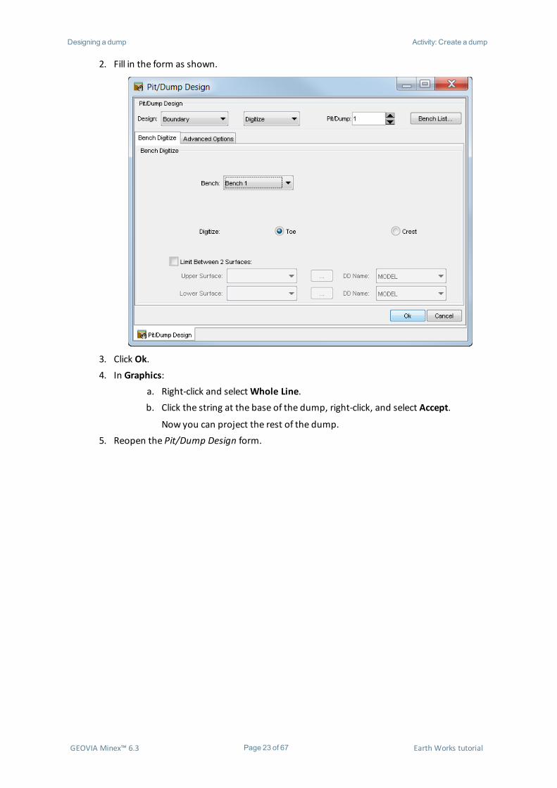
2. Fill in the form as shown.
3. Click Ok.4. In Graphics:
a. Right-click and selectWhole Line.b. Click the string at the base of the dump, right-click, and select Accept.
Now you can project the rest of the dump.5. Reopen the Pit/Dump Design form.
GEOVIA Minex™ 6.3 Page 23 of 67 Earth Works tutorial
Designing a dump Activity: Create a dump
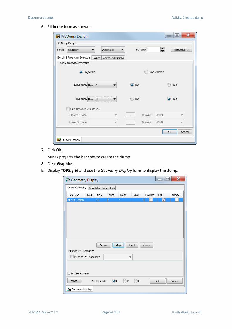
6. Fill in the form as shown.
7. Click Ok.
Minex projects the benches to create the dump.8. Clear Graphics.9. Display TOPS.grid and use theGeometry Display form to display the dump.
GEOVIA Minex™ 6.3 Page 24 of 67 Earth Works tutorial

Designing a dump Activity: Compute the dump surface
10. Save the changes to the geometry file.
Activity: Compute the dump surface
1. Select OP Design > Compute Pit/Dump Surface.
The Compute Pit/Dump Surface form appears.2. Fill in the form as shown.
3. Click Ok.
GEOVIA Minex™ 6.3 Page 25 of 67 Earth Works tutorial

Designing a dump Activity: Calculate the dump volume
Minex generates the grid of the dump surface.
Activity: Calculate the dump volume
1. Select Grid > Volumes.
TheGrid Volumes form opens.2. Fill in the form as shown.
3. Click Ok.
Minex calculates the volume of the dump, and generates a report in theOutput
Window.
GEOVIA Minex™ 6.3 Page 26 of 67 Earth Works tutorial

Designing a dump Activity: Calculate the dump volume
Note: The dump volume is significantly less than themax spoil volume. This is because
the dump has not been built to themaximum height and volume has been lost in berms.
GEOVIA Minex™ 6.3 Page 27 of 67 Earth Works tutorial
Designing amulti-benchMaxSpoil Activity: Create amulti-benchmaxspoil
Designing a multi-bench Max SpoilYou can use theMax Spoil function to create polygons that represent successive time periods. For
example, you could create polygons to represent successive years, and display the polygons in
different colours.
Activity: Create a multi-bench max spoil
1. In theMinex Explorer, expand theMODEL grid folder, right-click TOPS, and chooseDis-
play and Open.
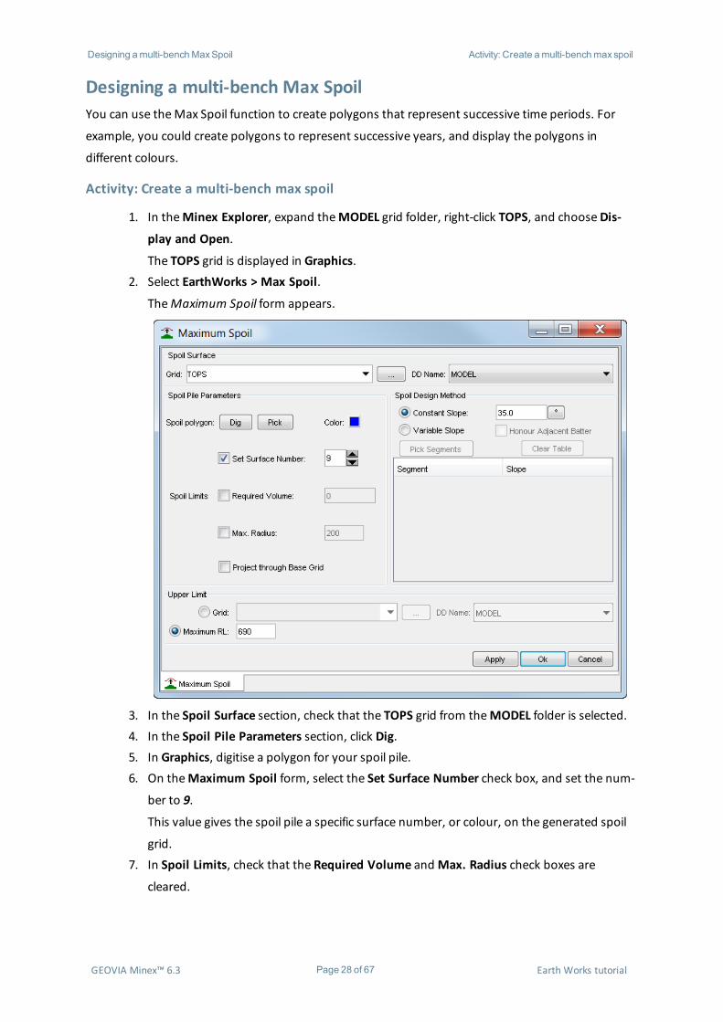
The TOPS grid is displayed in Graphics.2. Select EarthWorks > Max Spoil.
TheMaximum Spoil form appears.
3. In the Spoil Surface section, check that the TOPS grid from theMODEL folder is selected.4. In the Spoil Pile Parameters section, click Dig.5. In Graphics, digitise a polygon for your spoil pile.6. On theMaximum Spoil form, select the Set Surface Number check box, and set the num-
ber to 9.
This value gives the spoil pile a specific surface number, or colour, on the generated spoil
grid.7. In Spoil Limits, check that the Required Volume andMax. Radius check boxes are
cleared.
GEOVIA Minex™ 6.3 Page 28 of 67 Earth Works tutorial
Designing amulti-benchMaxSpoil Activity: Create amulti-benchmaxspoil
You can enter a volume, radius, or both, and Minex will generate a spoil pile that meets
the requirements.8. In the Spoil Design Method section, leave Constant Slope selected, and leave the default
value 35° in place.
A constant slope, 35°, is used for all sides of the generated pile.
Tip: To generate a pile with a variety of slopes, select the Variable Slope option, andclick Pick Segments. You can then select a segment of the spoil polygon, and assign a
slope value to each segment.9. In theUpper Limit section, selectMaximum RL, and type the height of your first bench.
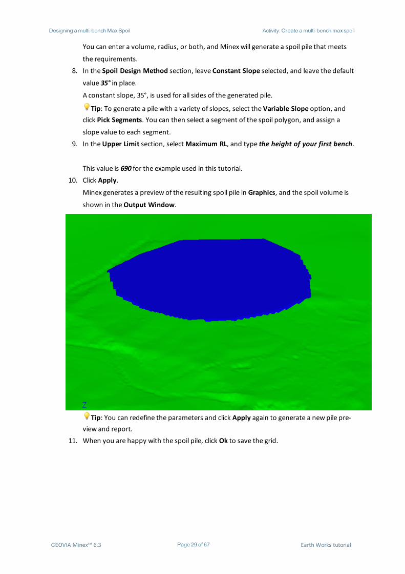
This value is 690 for the example used in this tutorial.10. Click Apply.
Minex generates a preview of the resulting spoil pile in Graphics, and the spoil volume is
shown in theOutput Window.
Tip: You can redefine the parameters and click Apply again to generate a new pile pre-view and report.
11. When you are happy with the spoil pile, click Ok to save the grid.
GEOVIA Minex™ 6.3 Page 29 of 67 Earth Works tutorial
Designing amulti-benchMaxSpoil Activity: Create amulti-benchmaxspoil
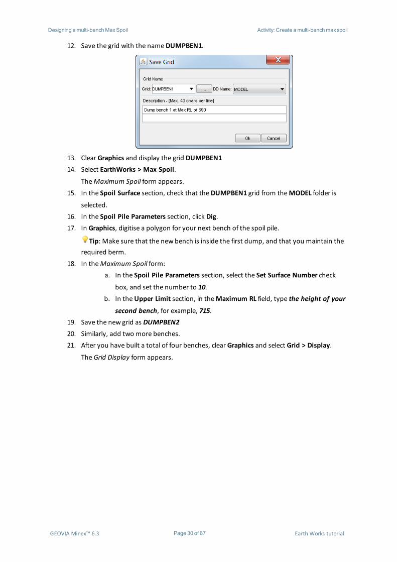
12. Save the grid with the nameDUMPBEN1.
13. Clear Graphics and display the grid DUMPBEN114. Select EarthWorks > Max Spoil.
TheMaximum Spoil form appears.15. In the Spoil Surface section, check that theDUMPBEN1 grid from theMODEL folder is
selected.16. In the Spoil Pile Parameters section, click Dig.17. In Graphics, digitise a polygon for your next bench of the spoil pile.
Tip: Make sure that the new bench is inside the first dump, and that you maintain therequired berm.
18. In theMaximum Spoil form:a. In the Spoil Pile Parameters section, select the Set Surface Number check
box, and set the number to 10.b. In theUpper Limit section, in theMaximum RL field, type the height of your
second bench, for example, 715.19. Save the new grid as DUMPBEN220. Similarly, add two more benches.21. After you have built a total of four benches, clear Graphics and select Grid > Display.
TheGrid Display form appears.
GEOVIA Minex™ 6.3 Page 30 of 67 Earth Works tutorial

Designing amulti-benchMaxSpoil Activity: Create amulti-benchmaxspoil
22. From theDD Name list, selectMODEL.23. From theGrid list, select DUMPBEN4.24. In the Plot Style section, clear the Lines check box, and select the Solid check box.25. In the Plot Color Mode section, select the Surface Color option, and click Setup.
The Surface Colour Setup form appears.
GEOVIA Minex™ 6.3 Page 31 of 67 Earth Works tutorial

Designing amulti-benchMaxSpoil Activity: Create amulti-benchmaxspoil
26. Select colours for the surfaces.
27. Click Ok.28. In theGrid Display form, click Ok.
The grid is displayed in Graphics, with each bench shown in a different colour.
Note: The edges of themax spoil might look wavy, depending on themesh size of the
grid being used. A finer mesh size gives a better looking edge, depending on themax grid
mesh points required. This activity started with a 25 X 25mesh of the topo. You can
attempt to make the edge less wavy by decreasing mesh size of the TOPS grid, using the
Grid Manipulate function.
GEOVIA Minex™ 6.3 Page 32 of 67 Earth Works tutorial

Designing a drag spoil Activity: Create drag spoil pile strings
Designing a drag spoilYou use the Drag Spoil function to create long narrow dumps that mimic a dragline dump. The
dumps are created using a crest string that sits on or above the crest of the dragline dump. Cones of
material with a repose angle are dumped from this crest string down to a surface, for example, the
pit floor. You can use a fine grid, such as 1m or 2m to produce a detailed display of the dragline
dump.
Because Drag Spoil generates a pile using a string as the peak of the spoil pile, you must generate
spoil pile strings above the design surface.
An appropriate spoil pile string:
l reflects themining equipment height and reach
l is a discontinuity strings
Note: The strings are typically created by offsetting and projecting from themining strip toes.
Activity: Create drag spoil pile strings
1. Clear Graphics.2. Check that THEDON.GM3 is open.3. In theMinex Explorer, expand theMODEL grid folder, right-click TOPS, and chooseDis-
play and Open.
The TOPS grid is displayed in Graphics.4. Select String > Create.5. Fill in the form as shown.
GEOVIA Minex™ 6.3 Page 33 of 67 Earth Works tutorial
Designing a drag spoil Activity: Create drag spoil pile strings
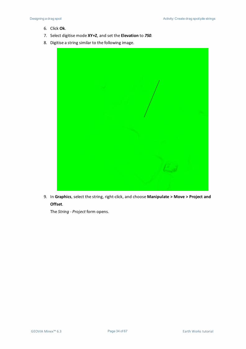
6. Click Ok.7. Select digitise mode XY+Z, and set the Elevation to 750.8. Digitise a string similar to the following image.
9. In Graphics, select the string, right-click, and chooseManipulate > Move > Project and
Offset.
The String - Project form opens.
GEOVIA Minex™ 6.3 Page 34 of 67 Earth Works tutorial
Designing a drag spoil Activity: Create drag spoil pile strings
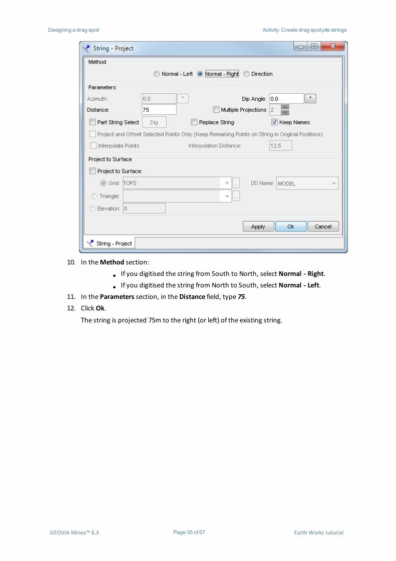
10. In theMethod section:
l If you digitised the string from South to North, select Normal - Right.
l If you digitised the string from North to South, select Normal - Left.11. In the Parameters section, in theDistance field, type 75.12. Click Ok.
The string is projected 75m to the right (or left) of the existing string.
GEOVIA Minex™ 6.3 Page 35 of 67 Earth Works tutorial
Designing a drag spoil Activity: Create drag spoil pile strings
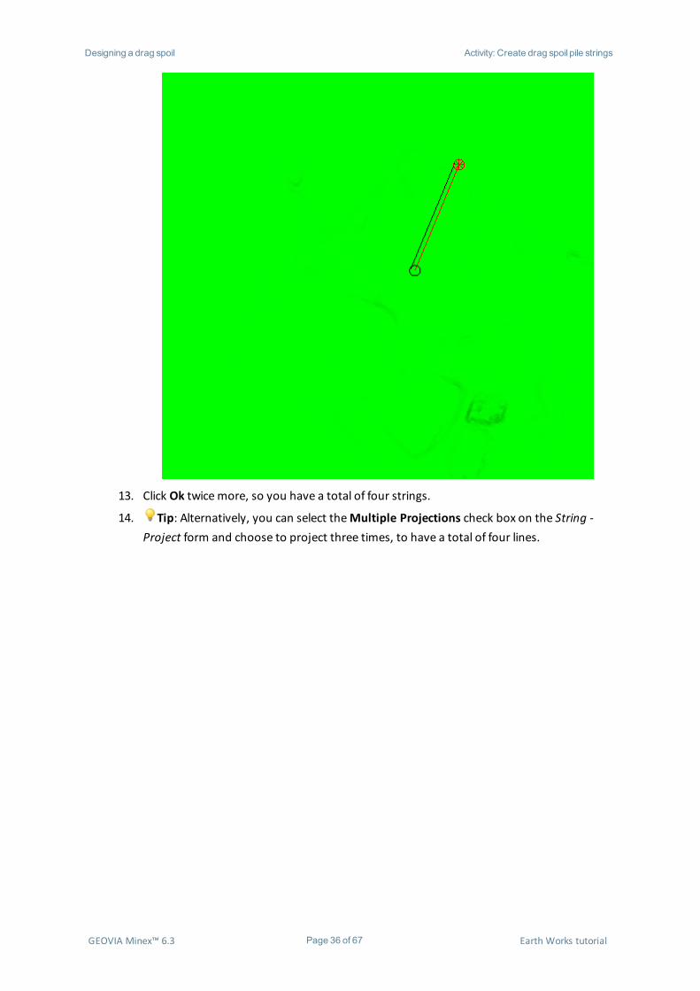
13. Click Ok twicemore, so you have a total of four strings.
14. Tip: Alternatively, you can select theMultiple Projections check box on the String -Project form and choose to project three times, to have a total of four lines.
GEOVIA Minex™ 6.3 Page 36 of 67 Earth Works tutorial
Designing a drag spoil Activity: Generate drag spoil piles
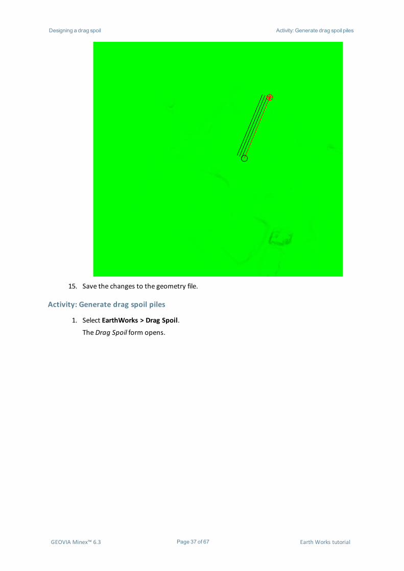
15. Save the changes to the geometry file.
Activity: Generate drag spoil piles
1. Select EarthWorks > Drag Spoil.
TheDrag Spoil form opens.
GEOVIA Minex™ 6.3 Page 37 of 67 Earth Works tutorial

Designing a drag spoil Activity: Generate drag spoil piles
2. In the Surface section, check that the TOPS grid is selected from theMODEL folder.
This is the surface on which you will design the drag spoil pile.3. In the Parameters section, click Pick.4. In Graphics, select the top line you created in the previous activity.5. On theDrag Spoil form, check that theMax Slope is set to 45°.
TheMax Slope is the slope for the spoil pile, and is measured from horizontal.6. Click theDisplay Color box and choose a colour, for example, blue.7. Check that the Peak Spacing value is 20.
The Peak Spacing is the distance between points generated at the peak of the spoil. A
smaller peak spacing distance will produce a smoother spoil pile. The peak spacing should
represent typical draglinemovements along the strip.8. Select the Set Surface Number check box.9. Check that the Peak Width is 10.
You should use a peak width where the dragline flat-tops the spoil.10. In the Limits section, check that the Required Volume andMax Radius check boxes are
cleared.
Note:
l If you select the Required Volume check box, you can set the wanted
volume for the spoil pile. If the volume specified is less than the volume
available to the peak string, the spoil pile builds up from the base to the
required volume and flat tops the spoil. If the required volume exceeds the
available room, an error is reported and the total volume achieved to the
limiting constraints is reported.
GEOVIA Minex™ 6.3 Page 38 of 67 Earth Works tutorial

Designing a drag spoil Activity: Generate drag spoil piles
l If you select theMax. Radius check box, you can set a maximum radius of
curvature for the spoil pile. Larger radii produce smoother spoil piles.11. Check that the Base Grid check box is cleared.
Note: If you selected the Base Grid check box, you can choose a limiting base grid for
the spoil pile. Occasionally, low angled spoil piles built beside pits generates a spoil pile
inside the pit. Selecting a limiting Base Grid such as the original topography prevents the
pit from being considered in pile generation.12. On theDrag Spoil form, click Apply.
Minex generates a drag spoil pile using the selected line as the peak.
13. Click Ok.
You are prompted to save the grid.14. Save the grid in theMODEL folder with the nameDUMPSP.
GEOVIA Minex™ 6.3 Page 39 of 67 Earth Works tutorial

Designing a drag spoil Activity: Generate drag spoil piles
15. Similarly, generate drag spoil piles for the remaining three strings, saving all drag spoils as
theDUMPSP grid.
Your final grid should resemble the one in the image below.
GEOVIA Minex™ 6.3 Page 40 of 67 Earth Works tutorial
Creating haul roads Activity: Create a road centre line
Creating haul roadsYou can use the Haul Road function to create a surface of a haul road and calculate cut and fill
volumes. It works on strings and triangulations and is a fast way of creating the desired surfaces.
You can create a haul road:
l that cuts into a dump
l that cuts into a high-wall with swell included in the cut-fill calculation
l from mine to mill to work out the volumes you require
For this tutorial, you will create a haul road that cuts into a dump.
You can create several haul roads with the triangulation of the new haul road patched into the
topography becoming the new design surface.
Note: You can only use the Haul Road function on triangulated design surfaces. If you have a grid,
but no triangulated surface, you must convert the grid to a triangulated surface before you can use
the Haul Road tool. Haul Road is not ideal for haul roads that go around steep bends, so for in-pit
high-wall roads, it is recommended that you use the Ramp Design tool.
Before you can generate a haul road, you must have a haul road centre line.
Activity: Create a road centre line
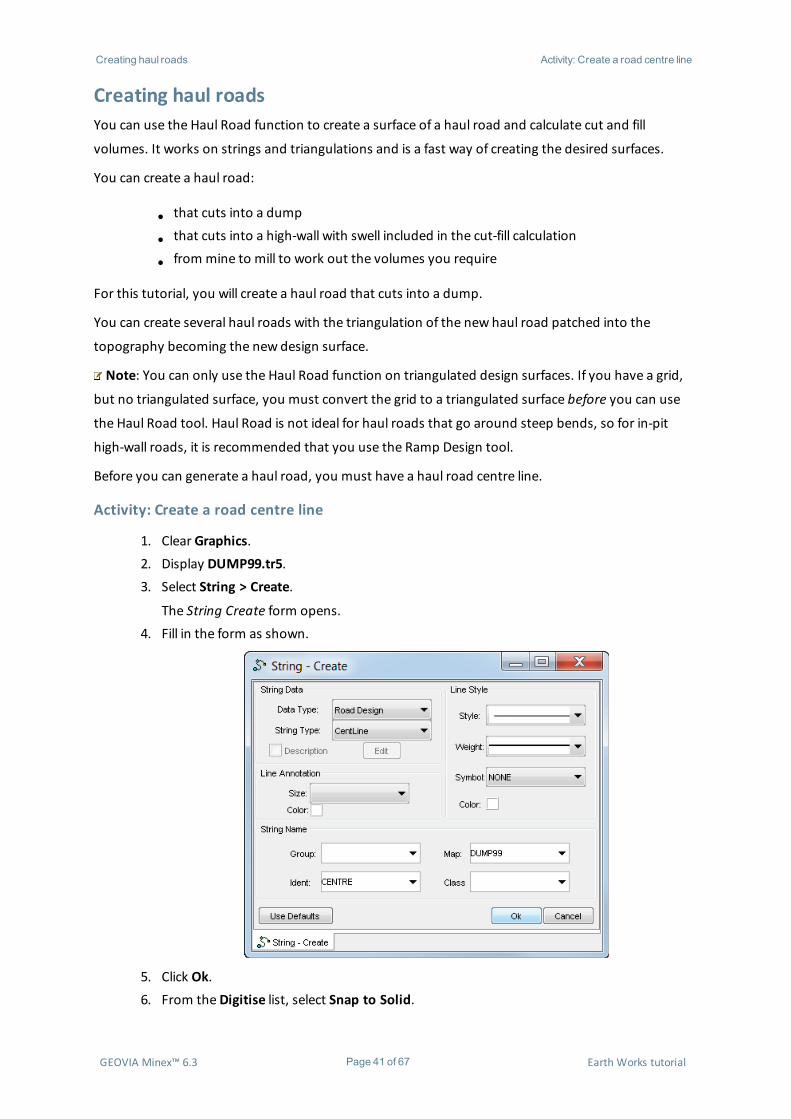
1. Clear Graphics.2. Display DUMP99.tr5.3. Select String > Create.
The String Create form opens.4. Fill in the form as shown.
5. Click Ok.6. From theDigitise list, select Snap to Solid.
GEOVIA Minex™ 6.3 Page 41 of 67 Earth Works tutorial
Creating haul roads Activity: Create a haul road
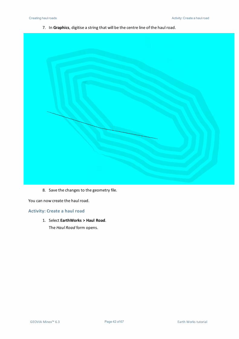
7. In Graphics, digitise a string that will be the centre line of the haul road.
8. Save the changes to the geometry file.
You can now create the haul road.
Activity: Create a haul road
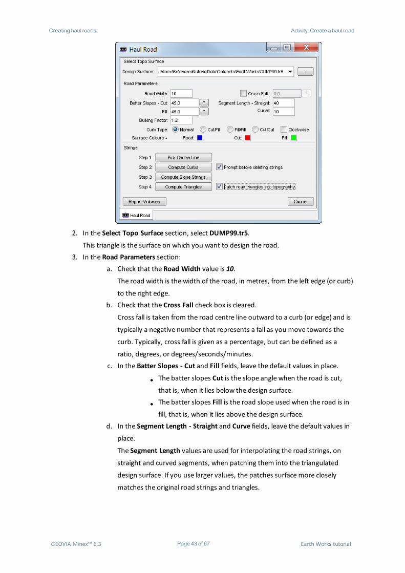
1. Select EarthWorks > Haul Road.
TheHaul Road form opens.
GEOVIA Minex™ 6.3 Page 42 of 67 Earth Works tutorial
Creating haul roads Activity: Create a haul road
2. In the Select Topo Surface section, select DUMP99.tr5.
This triangle is the surface on which you want to design the road.3. In the Road Parameters section:
a. Check that the Road Width value is 10.
The road width is the width of the road, in metres, from the left edge (or curb)
to the right edge.b. Check that the Cross Fall check box is cleared.
Cross fall is taken from the road centre line outward to a curb (or edge) and is
typically a negative number that represents a fall as you move towards the
curb. Typically, cross fall is given as a percentage, but can be defined as a
ratio, degrees, or degrees/seconds/minutes.c. In the Batter Slopes - Cut and Fill fields, leave the default values in place.
l The batter slopes Cut is the slope angle when the road is cut,
that is, when it lies below the design surface.
l The batter slopes Fill is the road slope used when the road is in
fill, that is, when it lies above the design surface.d. In the Segment Length - Straight and Curve fields, leave the default values in
place.
The Segment Length values are used for interpolating the road strings, on
straight and curved segments, when patching them into the triangulated
design surface. If you use larger values, the patches surfacemore closely
matches the original road strings and triangles.
GEOVIA Minex™ 6.3 Page 43 of 67 Earth Works tutorial
Creating haul roads Activity: Create a haul road
e. Check that the Bulking Factor is 1.2.
The swell or bulking factor is used when computing the total mass balance of
the cut/fill components of the road design.f. Under Curb Type, select theNormal option.
The Curb Type defines how the haul road curbs, or edges, are located in rela-
tion to the nominal design centre line. The Curb Type provides an approx-
imatemechanism to shift the road into cut material, fill material, or a to
achieve an approximate balance between cut and fill. There are four curb
types available:
l Normal: Road edges are equidistant, that is, half the road width
either side of the road centre line.
l Fill/Fill: Road edges aremoved laterally, half the road width to
the right, into the topography surface, so that the road surface
is completely fill material.
l Cut/Cut: Road edges aremoved laterally, half the road width to
the left, away from the topography surface, so that the road sur-
face is completely cut material.
l Cut/Fill: Road edges aremoved laterally in relation to the ori-
ginal centre line so that the right edge of the road is coincident
with the nominal centre line at the road end. The road is there-
fore completely in cut at the road start, and completely in fill at
the road end.g. Check that the Clockwise check box is cleared.
The Curb Type options are subject to the string direction and the Clockwise
check box. For example, Minex will cut/fill clockwise around the string if the
Clockwise check box is selected, and anti-clockwise if the check box is cleared.h. Select Surface Colours to represent the areas of the triangulated surface that
are road, cut, and fill.
Note: These colours are saved as surface colours in the triangle itself.4. In the Strings section, select the Patch road triangles into topography check box.
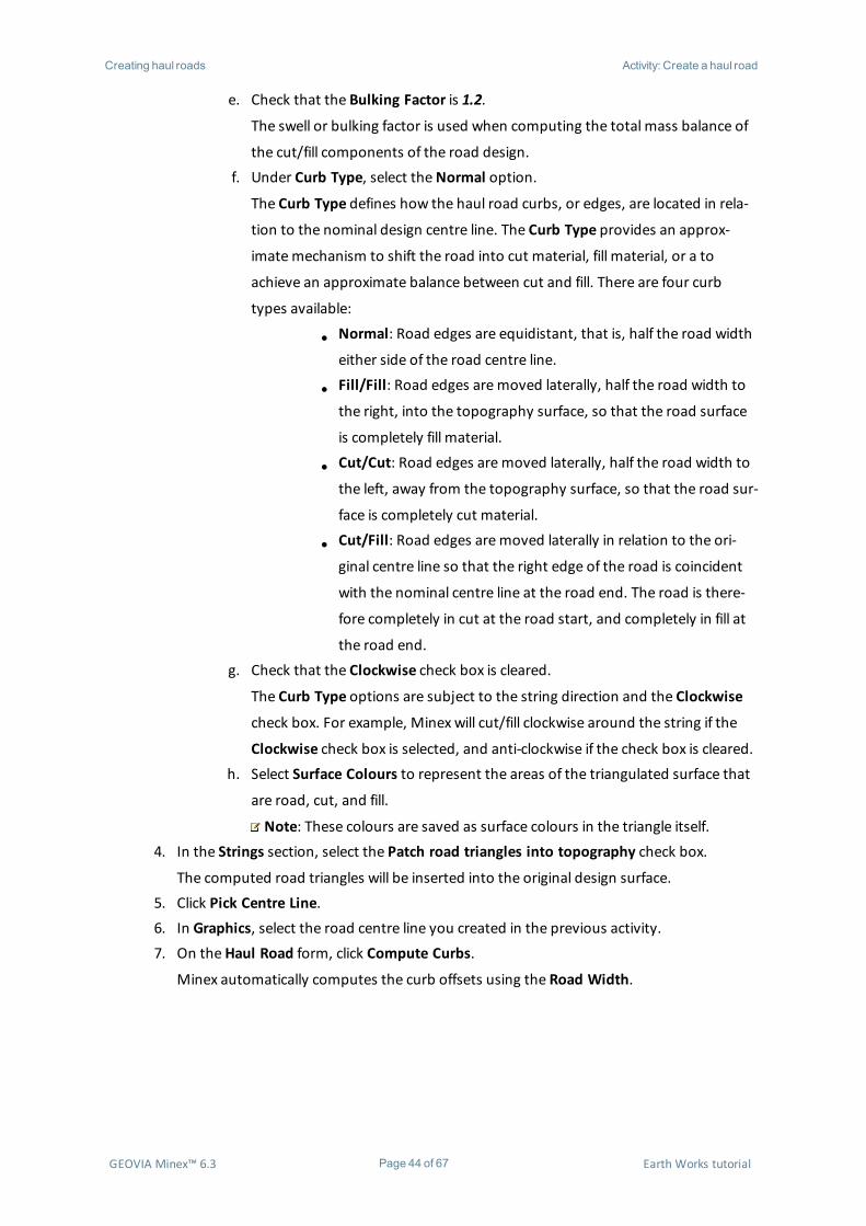
The computed road triangles will be inserted into the original design surface.5. Click Pick Centre Line.6. In Graphics, select the road centre line you created in the previous activity.7. On theHaul Road form, click Compute Curbs.
Minex automatically computes the curb offsets using the Road Width.
GEOVIA Minex™ 6.3 Page 44 of 67 Earth Works tutorial
Creating haul roads Activity: Create a haul road
8. Click Compute Slope Strings.
You can now see the intersection of the projected curbs and the design surface.
GEOVIA Minex™ 6.3 Page 45 of 67 Earth Works tutorial

Creating haul roads Activity: Create a haul road
GEOVIA Minex™ 6.3 Page 46 of 67 Earth Works tutorial

Creating haul roads Activity: Create a haul road
9. Click Compute Triangles.
You are prompted to save the computed road triangles.
GEOVIA Minex™ 6.3 Page 47 of 67 Earth Works tutorial
Creating haul roads Activity: Create a haul road
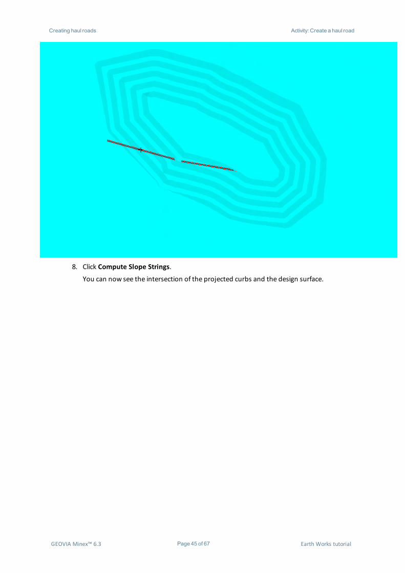
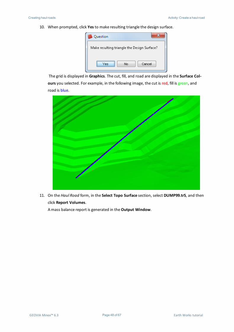
10. When prompted, click Yes to make resulting triangle the design surface.
The grid is displayed in Graphics. The cut, fill, and road are displayed in the Surface Col-
ours you selected. For example, in the following image, the cut is red, fill is green, and
road is blue.
11. On theHaul Road form, in the Select Topo Surface section, select DUMP99.tr5, and then
click Report Volumes.
Amass balance report is generated in theOutput Window.
GEOVIA Minex™ 6.3 Page 48 of 67 Earth Works tutorial

Creating haul roads Activity: Create a haul road
12. In theMinex Explorer, select the new surface, right-click, and chooseDisplay and Open.
GEOVIA Minex™ 6.3 Page 49 of 67 Earth Works tutorial

Regrading spoil piles Activity: Compute spoil regrade
Regrading spoil pilesYou use the Spoil Regrade function to produce an optimum regraded spoil surface by minimising the
volume of, and distance that waste is pushed. The regraded spoil surface is confined to specified
physical constraints. Regrade spoil is suitable for reclamation work where large areas of dragline or
truck and shovel spoils require reshaping to suit a final landform. You can regrademaximum spoil
dumps or drag spoil dumps. For this tutorial, you will regrade drag spoil piles.
Activity: Compute spoil regrade
1. Clear Graphics.2. Display and open DUMP.grid from theMODEL grid folder.3. Choose SpoilRegrade > Compute.
The Spoil Regrade - Compute form opens.
GEOVIA Minex™ 6.3 Page 50 of 67 Earth Works tutorial

Regrading spoil piles Activity: Compute spoil regrade
4. In the Select Spoil Surface section:a. From theDD Name list, selectMODEL.b. From the Spoil Surface list, select DUMP.
The spoil surface is the surface you want to regrade. The input grid should be
of a mesh size suitable for spoil optimisation, showing sufficient detail but
without being so fine that there are too many mesh points to compute. Typ-
ically, grids of 10m x 10m mesh size or 5m x 5m mesh size are suitable. If you
need to regrade a large area, it may be necessary to split the area into smaller
areas and treat the optimisation as two or more separate runs.
GEOVIA Minex™ 6.3 Page 51 of 67 Earth Works tutorial
Regrading spoil piles Activity: Compute spoil regrade
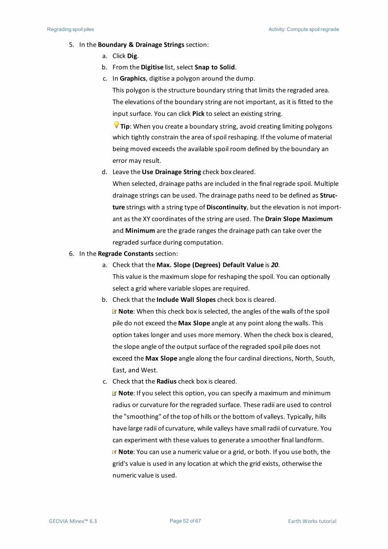
5. In the Boundary & Drainage Strings section:a. Click Dig.b. From theDigitise list, select Snap to Solid.c. In Graphics, digitise a polygon around the dump.
This polygon is the structure boundary string that limits the regraded area.
The elevations of the boundary string are not important, as it is fitted to the
input surface. You can click Pick to select an existing string.
Tip: When you create a boundary string, avoid creating limiting polygonswhich tightly constrain the area of spoil reshaping. If the volume ofmaterial
being moved exceeds the available spoil room defined by the boundary an
error may result.d. Leave theUse Drainage String check box cleared.
When selected, drainage paths are included in the final regrade spoil. Multiple
drainage strings can be used. The drainage paths need to be defined as Struc-
ture strings with a string type ofDiscontinuity, but the elevation is not import-
ant as the XY coordinates of the string are used. TheDrain Slope Maximum
andMinimum are the grade ranges the drainage path can take over the
regraded surface during computation.6. In the Regrade Constants section:
a. Check that theMax. Slope (Degrees) Default Value is 20.
This value is themaximum slope for reshaping the spoil. You can optionally
select a grid where variable slopes are required.b. Check that the Include Wall Slopes check box is cleared.
Note: When this check box is selected, the angles of the walls of the spoil
pile do not exceed theMax Slope angle at any point along the walls. This
option takes longer and uses morememory. When the check box is cleared,
the slope angle of the output surface of the regraded spoil pile does not
exceed theMax Slope angle along the four cardinal directions, North, South,
East, and West.c. Check that the Radius check box is cleared.
Note: If you select this option, you can specify a maximum and minimum
radius or curvature for the regraded surface. These radii are used to control
the "smoothing" of the top of hills or the bottom of valleys. Typically, hills
have large radii of curvature, while valleys have small radii of curvature. You
can experiment with these values to generate a smoother final landform.
Note: You can use a numeric value or a grid, or both. If you use both, the
grid's value is used in any location at which the grid exists, otherwise the
numeric value is used.
GEOVIA Minex™ 6.3 Page 52 of 67 Earth Works tutorial
Regrading spoil piles Activity: Compute spoil regrade
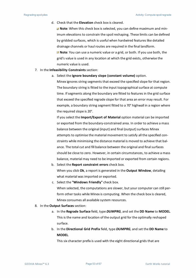
d. Check that the Elevation check box is cleared.
Note: When this check box is selected, you can definemaximum and min-
imum elevations to constrain the spoil reshaping. These limits can be defined
by gridded surfaces, which is useful when hardwired features like detailed
drainage channels or haul routes are required in the final landform.
Note: You can use a numeric value or a grid, or both. If you use both, the
grid's value is used in any location at which the grid exists, otherwise the
numeric value is used.7. In the Infeasibility Constraints section:
a. Select the Ignore boundary slope (constant volume) option.
Minex ignores string segments that exceed the specified slope for that region.
The boundary string is fitted to the input topographical surface at compute
time. If segments along the boundary are fitted to features in the grid surface
that exceed the specified regrade slope for that area an error may result. For
example, a boundary string segment fitted to a 70° highwall in a region where
the required slope is 20°.
If you select the Import/Export of Material option material can be imported
or exported from the boundary-constrained area. In order to achieve a mass
balance between the original (input) and final (output) surfaces Minex
attempts to optimise thematerial movement to satisfy all the specified con-
straints while minimising the distancematerial is moved to achieve that bal-
ance. The total cut and fill balance between the original and final surfaces
should be close to zero. However, in certain circumstances, to achieve a mass
balance, material may need to be imported or exported from certain regions.b. Select the Report constraint errors check box.
When you click Ok, a report is generated in theOutput Window, detailing
what material was imported or exported.c. Select the "Windows Friendly" check box.
When selected, the computations are slower, but your computer can still per-
form other tasks whileMinex is computing. When the check box is cleared,
Minex consumes all available system resources.8. In theOutput Surfaces section:
a. In the Regrade Surface field, typeDUMPRG, and set theDD Name toMODEL.
This is the name and location of the output grid for the optimally reshaped
surface.b. In theDirectional Grid Prefix field, typeDUMPRG, and set theDD Name to
MODEL.
This six character prefix is used with the eight directional grids that are
GEOVIA Minex™ 6.3 Page 53 of 67 Earth Works tutorial

Regrading spoil piles Activity: Display regraded spoil grids
generated. Minex appends a suffix that indicates which quadrant the grid
relates to. Each individual grid represents the volume pushed in that par-
ticular direction.c. Check that theMesh Size is 25.
TheMesh Size is themesh cell size at which the optimisation is run. This value
overrides the input mesh size of the topographical grid.9. Click Ok.
Minex generates nine grids; a final spoil grid and eight directional volume grids. These dir-
ectional grids show the volume ofmaterial pushed from a mesh point to the surrounding
eight mesh points, N, NE, E, SE, S, SW, W, and NW. You can use theDisplay and Report
function to display regraded spoil grids with arrows scaled and coloured by the volume of
material moved.10. Clear Graphics and display and open the regraded surface.
Activity: Display regraded spoil grids
1. If it is not already displayed, display DUMPRG.grid.2. Select SpoilRegrade > Report and Display.
The Spoil Regrade - Report and Display form opens.3. Fill in the form as shown.
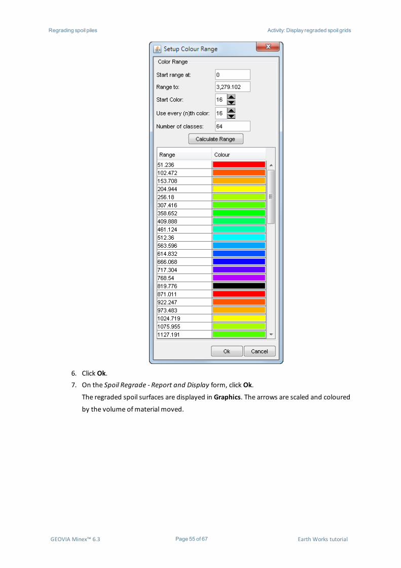
4. In theMode section, click Setup.
The Setup Colour Range form opens.5. Fill in the form as shown.
Tip: Click Calculate Range to populate the Colour Range table.
GEOVIA Minex™ 6.3 Page 54 of 67 Earth Works tutorial
Regrading spoil piles Activity: Display regraded spoil grids
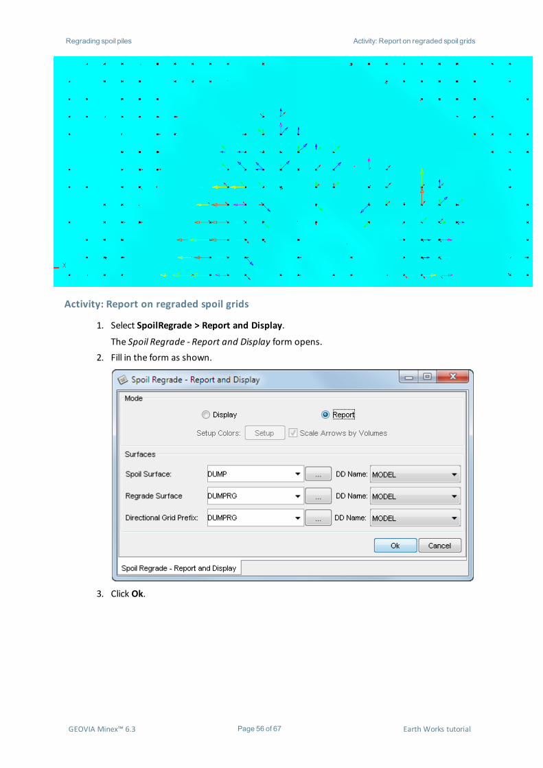
6. Click Ok.7. On the Spoil Regrade - Report and Display form, click Ok.
The regraded spoil surfaces are displayed in Graphics. The arrows are scaled and coloured
by the volume ofmaterial moved.
GEOVIA Minex™ 6.3 Page 55 of 67 Earth Works tutorial
Regrading spoil piles Activity: Report on regraded spoil grids
Activity: Report on regraded spoil grids
1. Select SpoilRegrade > Report and Display.
The Spoil Regrade - Report and Display form opens.2. Fill in the form as shown.
3. Click Ok.
GEOVIA Minex™ 6.3 Page 56 of 67 Earth Works tutorial

Regrading spoil piles Activity: Report on regraded spoil grids
The directional push report is generated in theOutput Window.
GEOVIA Minex™ 6.3 Page 57 of 67 Earth Works tutorial
Rehabilitating a surface Activity: Report on regraded spoil grids
Rehabilitating a surface
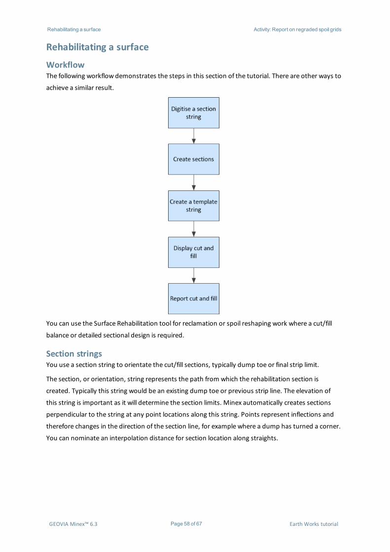
WorkflowThe following workflow demonstrates the steps in this section of the tutorial. There are other ways to
achieve a similar result.
You can use the Surface Rehabilitation tool for reclamation or spoil reshaping work where a cut/fill
balance or detailed sectional design is required.
Section stringsYou use a section string to orientate the cut/fill sections, typically dump toe or final strip limit.
The section, or orientation, string represents the path from which the rehabilitation section is
created. Typically this string would be an existing dump toe or previous strip line. The elevation of
this string is important as it will determine the section limits. Minex automatically creates sections
perpendicular to the string at any point locations along this string. Points represent inflections and
therefore changes in the direction of the section line, for example where a dump has turned a corner.
You can nominate an interpolation distance for section location along straights.
GEOVIA Minex™ 6.3 Page 58 of 67 Earth Works tutorial
Rehabilitating a surface Activity: Digitise a section string
Activity: Digitise a section string
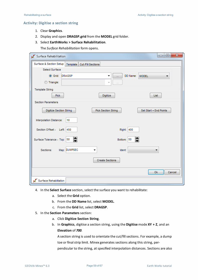
1. Clear Graphics.2. Display and open DRAGSP.grid from theMODEL grid folder.3. Select EarthWorks > Surface Rehabilitation.
The Surface Rehabilitation form opens.
4. In the Select Surface section, select the surface you want to rehabilitate:a. Select theGrid option.b. From theDD Name list, selectMODEL.c. From theGrid list, select DRAGSP.
5. In the Section Parameters section:a. Click Digitize Section String.b. In Graphics, digitise a section string, using theDigitisemode XY + Z, and an
Elevation of 700.
A section string is used to orientate the cut/fill sections. For example, a dump
toe or final strip limit. Minex generates sections along this string, per-
pendicular to the string, at specified interpolation distances. Sections are also
GEOVIA Minex™ 6.3 Page 59 of 67 Earth Works tutorial

Rehabilitating a surface Activity: Digitise a section string
created at any inflection points along the string as they represent changes in
the orientation of the cut/fill planes.
Alternatively, you could click Pick Section String, to choose an existing sec-
tion string, or Set Start + End Points to digitise start and end points on an
existing string, between which the rehabilitation sections are created.c. In the Interpolation Distance field, leave the default value, 10, in place.
The interpolation distance is the nominal section spacing on the section
string. Minex creates sections at the distance specified, additional sections are
created at each point on the section string. The interpolation distance is crit-
ical, too many points results in many unnecessary cut/fill operations, too few,
and the cut/fill surface created may be less than optimal.d. In the Section Offset - Left field, type 450.e. In the Right field, type 400.
The section offset is the section width either side of the section line.
Tip: Make sure that the offset is larger than the area on which you want toperform cut/fill work, as a narrow section makes it harder to view the different
sections.f. Check that the Surface Tolerance - Top and Bottom values are 50.
The Surface Tolerance values provide additional height above and below the
surface on each section.g. In the Sections: Map field, typeDUMPSEC.
GEOVIA Minex™ 6.3 Page 60 of 67 Earth Works tutorial

Rehabilitating a surface Activity: Create a template string and compute cut/fill
6. Click the Template tab, and fill in as shown.
7. Click the Surface & Section Setup tab, and click Create Sections.
Minex opens theDrafting tab, and displays the first section.
Activity: Create a template string and compute cut/fill
1. On the Surface Rehabilitation form, in the Template String section, click Digitize.2. In Graphics, digitise a template string.
Note: Youmust digitise from left to right, across Graphics.
A template string is a "floating" string that you use to examine various cut/fill scenarios.
GEOVIA Minex™ 6.3 Page 61 of 67 Earth Works tutorial

Rehabilitating a surface Activity: Create a template string and compute cut/fill
Note: Because the Intersect Template with Section String check box on the Template
tab is selected, your template string is moved to intersect with the section string, indic-
ated by the red flag.3. On the Surface Rehabilitation form, click the Cut/Fill Sections tab.
The Section Details section lists the currently displayed section. You can use the Section
list to display another section.4. In the Compute Cut/Fill section:
a. Check that the Automatic Cut/Fill Balance check box is cleared.
Note: When this option is selected, the template string is automatically
adjusted up or down to balance cut/fill. It also makes theNett Cut/Fill Area
Balance tolerance +/- available, which is the tolerance on any area balance.
Tip: For this option to work, the template string must intercept the surfacetwice.
GEOVIA Minex™ 6.3 Page 62 of 67 Earth Works tutorial
Rehabilitating a surface Activity: Create a template string and compute cut/fill
b. Check that the Swell Factor check box is cleared.
The swell factor can be used for insitu material that must be cut. If a swell
factor is used, all cut material on the section has this factor applied to the
area.c. Check that the Ignore Cut/Fill areas smaller than check box is cleared.
If you select this option, you can specify theminimum acceptable area for
cut/fill computation. Areas smaller than the specified area are ignored so that
small areas above or below the template string do not unreasonably influence
cut/fill balance computation.
Note: The Bearing, Distance, andMove Template controls are used to shift
the template string on a section to derive new cut/fill scenarios. You can click
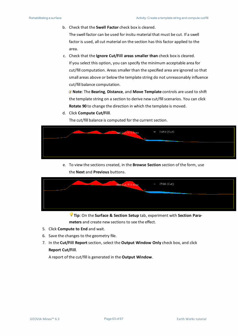
Rotate 90 to change the direction in which the template is moved.d. Click Compute Cut/Fill.
The cut/fill balance is computed for the current section.
e. To view the sections created, in the Browse Section section of the form, use
theNext and Previous buttons.
Tip: On the Surface & Section Setup tab, experiment with Section Para-meters and create new sections to see the effect.
5. Click Compute to End and wait.6. Save the changes to the geometry file.7. In the Cut/Fill Report section, select theOutput Window Only check box, and click
Report Cut/Fill.
A report of the cut/fill is generated in theOutput Window.
GEOVIA Minex™ 6.3 Page 63 of 67 Earth Works tutorial

Rehabilitating a surface Activity: Create a template string and compute cut/fill
GEOVIA Minex™ 6.3 Page 64 of 67 Earth Works tutorial

Rehabilitating a surface Activity: Create a template string and compute cut/fill
8. Use theGeometry Display form to view the sections of the rehabilitation.
The sections are displayed in Graphics.
GEOVIA Minex™ 6.3 Page 65 of 67 Earth Works tutorial

Rehabilitating a surface Activity: Create a template string and compute cut/fill
These section lines can then be used to create a triangle or grid. While the report gives the cut and fill
for each section, alternately the total volume can be obtained between the grid surface created and
theDRAGSP grid.
GEOVIA Minex™ 6.3 Page 66 of 67 Earth Works tutorial

Summary Activity: Create a template string and compute cut/fill
SummaryCongratulations on completing this tutorial. You should now understand the EarthWorks and Spoil
Regrade functions ofMinex. You have learnt a number of concepts and topics including how to:
l design dumps using themax spoil tool
l design a dump using the drag spoil tool
l create a haul road centre line
l create a haul road that cuts into a dump
l regrade a spoil pile
l rehabilitate a surface:
l create a cross section
l edit the cross section to create a slope
l cut and fill the slope
l create an optimised cut/fill surface
GEOVIA Minex™ 6.3 Page 67 of 67 Earth Works tutorial