Embed Size (px)
Citation preview
Division / Business Unit: Inland Rail
Function: Earthworks (Construction)
Document Type: Specification
© Australian Rail Track Corporation Limited (ARTC)
Disclaimer
This document has been prepared by ARTC for internal use and may not be relied on by any other party without ARTC’s prior wri tten consent. Use of this document shall be subject
to the terms of the relevant contract with ARTC.
ARTC and its employees shall have no liability to unauthorised users of the information for any loss, damage, cost or expense incurred or arising by reason of an unauthorised user
using or relying upon the information in this document, whether caused by error, negligence, omission or misrepresentation in this document.
This document is uncontrolled when printed.
Authorised users of this document should visit ARTC’s intranet or extranet (www.artc.com.au) to access the latest version of this document.
Page 1 of 35
Earthworks Materials Specification
ETC-08-03
Applicability
NSW QLD VIC SMS
Publication Requirement
Internal / External
Primary Source
0-9000-PEN-00-SP-1002 – Rev 2.1
Document Status
Version # Date Reviewed Prepared by Reviewed by Endorsed Approved
1.2 25 Sep 2019 System and
Procedure
Administrator
Standards Manager
Standards
General Manager
Technical Standards
02/10/2019
Amendment Record
Amendment
Version #
Date Reviewed Clause Description of Amendment
1.0 12 May 2017 First Issue
1.1 23 Nov 2017 All Revision to align with issue of ETC-08-04
Addition of section for geotextile classification and compliance
Additional update to scope following ONRSR comments, as
well as clauses 4.1, 4.7 & 4.11
1.2 25 Sep 2019 1.5 Add Procedure Owner section and remove ‘Confidential’ from
title page.
Earthworks Materials Specification
ETC-08-03
Table of Contents
This document is uncontrolled when printed. Version Number: 1.2 Date Reviewed: 25 Sep 2019 Page 2 of 35
Table of Contents
Table of Contents ............................................................................................................................................. 2
List of Figures ................................................................................................................................................... 4
List of Tables ..................................................................................................................................................... 4
1 Scope and Purpose ................................................................................................................................ 5
1.1 Purpose .......................................................................................................................................... 5
1.2 Scope ............................................................................................................................................. 5
1.3 Precedence .................................................................................................................................... 5
1.4 Programme Documents ................................................................................................................. 5
1.5 Procedure Owner ........................................................................................................................... 6
2 Definitions ............................................................................................................................................... 7
3 Codes and Standards .......................................................................................................................... 13
4 Earthworks Materials ........................................................................................................................... 14
4.1 General ......................................................................................................................................... 14
4.2 Capping Material .......................................................................................................................... 14
4.3 Structural Fill Material .................................................................................................................. 15
4.4 General Earth Fill Material ........................................................................................................... 16
4.5 Select Fill Adjacent to Structures ................................................................................................. 18
4.6 Bedding Sand ............................................................................................................................... 19
4.7 Rockfill .......................................................................................................................................... 19
4.8 Rock Protection ............................................................................................................................ 20
4.9 Drainage Blanket Material ............................................................................................................ 20
4.10 Other Drainage Materials ............................................................................................................. 21
4.11 Unsuitable Material ...................................................................................................................... 21
4.11.1 General 21
4.11.2 Inherently Unsuitable .................................................................................................................... 21
4.11.3 Unsuitable Materials by Virtue of Position .................................................................................... 21
4.11.4 Unsuitable by Moisture Content .................................................................................................... 21
4.12 Stabilised Material ........................................................................................................................ 21
5 Geotextiles ............................................................................................................................................ 23
5.1 General ......................................................................................................................................... 23
5.2 Strength ........................................................................................................................................ 23
5.3 Filtration ........................................................................................................................................ 24
Earthworks Materials Specification
ETC-08-03
Table of Contents
This document is uncontrolled when printed. Version Number: 1.2 Date Reviewed: 25 Sep 2019 Page 3 of 35
6 Quality Plan ........................................................................................................................................... 25
6.1 Contractor’s Project Quality Plan ................................................................................................. 25
6.2 Variation of Testing Frequencies ................................................................................................. 25
6.3 Alternative Test Methods ............................................................................................................. 25
Appendix A – Specification Variation Compliance Forms ......................................................................... 26
A1. Variance to Design Material Compliance ......................................................................................... 26
A2. Variance to Formation Geometry Specific Design Requirements ................................................... 33
A3. Variance to Cutting Geometry Project Specific Design Requirements ............................................ 34
Appendix B – Changes to ARTC Standards Relating to this Specification .............................................. 35
Earthworks Materials Specification
ETC-08-03
List of Figures
This document is uncontrolled when printed. Version Number: 1.2 Date Reviewed: 25 Sep 2019 Page 4 of 35
List of Figures
Figure 1 Schematic of Homogeneous Embankment Cross Section .......................................................... 11
Figure 2 Schematic of Zoned Embankment Cross Section ....................................................................... 11
Figure 3 Schematic of Cutting Cross Section ........................................................................................... 12
Figure 4 Schematic of Formation and Track ............................................................................................. 12
List of Tables
Table 1 Contractual Definitions .................................................................................................................. 7
Table 2 Railway Construction Definitions................................................................................................... 8
Table 3 Abbreviations............................................................................................................................... 10
Table 4 Capping Material ......................................................................................................................... 14
Table 5 Structural Fill Material ................................................................................................................. 16
Table 6 General Earth Fill Material .......................................................................................................... 17
Table 7 Select Fill Material ....................................................................................................................... 18
Table 8 Bedding Sand Material ................................................................................................................ 19
Table 9 Rockfill Material ........................................................................................................................... 19
Table 10 Drainage Blanket Material ........................................................................................................... 20
Table 11 Geotextile Strength Classifications ............................................................................................. 23
Table 12 Geotextile Filtration Classifications ............................................................................................. 24
Table 13 Capping Material Variance .......................................................................................................... 26
Table 14 Structural Fill Material Variance .................................................................................................. 27
Table 15 General Earth Fill Material Variance ........................................................................................... 28
Table 16 Select Fill Material ....................................................................................................................... 29
Table 17 Bedding Sand Material Variance ................................................................................................. 30
Table 18 Rockfill Material Variance ............................................................................................................ 31
Table 19 Drainage Blanket Material Variance ............................................................................................ 32
Table 20 Design Specific Formation and Shoulder Geometry Requirements ........................................... 33
Table 21 Design Specific Cutting Geometry Requirements....................................................................... 34
Earthworks Materials Specification
ETC-08-03
Scope and Purpose
This document is uncontrolled when printed. Version Number: 1.2 Date Reviewed: 25 Sep 2019 Page 5 of 35
1 Scope and Purpose
1.1 Purpose
The purpose of this Specification is to provide earthworks material types and compliance
requirements which facilitate construction of a stable foundation and formation suitable for ballast
and track to be constructed upon along with associated earthworks for drainage elements, such
that it maintains stability and meets safety and performance standards over the design life.
1.2 Scope
This Specification defines earthworks material properties for construction of railway earthworks
for the Inland Rail Programme (the Programme).
This Specification is intended to be tailored to suit the materials available within the Programme.
The Contractor is required to consider the design information and values provided in the following
sections as minimum requirements, and proposed changes by the Contractor to specification
requirements are required to be detailed in Appendix A of this Specification. The proposed values
must be consistent with design requirements and acceptance of the proposed values is at the
sole discretion of the Superintendent.
The BoD allows for unconventional alternative engineered formations and materials, such as use
of stabilised materials or the use of geosynthetics or other solutions, to be proposed by the
Designer or Contractor. Proposal of alternative formation design values presented within
Appendix B shall be subject to appropriate ARTC review and acceptance. If an alternative design
is accepted, material properties and other relevant information must be documented in a Project
Specific Specification and appended to this Specification. The Project Specific Specification must
be approved by the Superintendent.
Where materials proposed in design are not detailed within this Specification, the Contractor must
specify the proposed materials and incorporate into Appendix A of this Specification, or document
those materials in a Project Specific Specification appended to this Specification.
1.3 Precedence
This Specification shall be considered first in an order of precedence, followed by the latest
version of ARTC document ETM-08-01 and ETC-08-02.
This specification has been developed in conjunction with a revised specification for construction
of earthworks, denoted herein as ETC-08-04. Where document ETC-08-04 is unavailable,
reference shall be made to ARTC Standard ETC-08-01. This Specification shall also be read in
conjunction with the Inland Rail Basis of Design (BoD) document (reference 2-9000-PEN-00-PR-
1000).
Where conflict exists between any statutory requirements, standards, reference documents,
specifications and this Specification, the most stringent requirement as determined by the
Superintendent will apply.
1.4 Programme Documents
The execution of earthworks in accordance with this Specification requires compliance to
overarching Programme requirements. The Contractor’s attention is drawn to the following
documents:
Earthworks Materials Specification
ETC-08-03
Scope and Purpose
This document is uncontrolled when printed. Version Number: 1.2 Date Reviewed: 25 Sep 2019 Page 6 of 35
• Project General Conditions of Contract;
• The Programme Environmental Management Plan;
• The Project Primary Approval Document and Conditions of Approval; and
• The Programme Quality Plan.
1.5 Procedure Owner
The Standards Manager is the Procedure Owner and is the initial point of contact for all queries
relating to this procedure.
Earthworks Materials Specification
ETC-08-03
Definitions
This document is uncontrolled when printed. Version Number: 1.2 Date Reviewed: 25 Sep 2019 Page 7 of 35
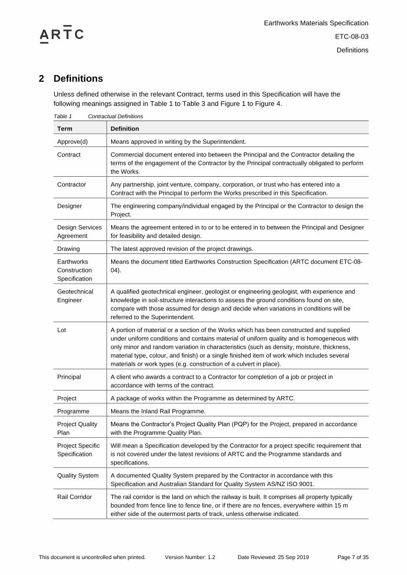
2 Definitions
Unless defined otherwise in the relevant Contract, terms used in this Specification will have the
following meanings assigned in Table 1 to Table 3 and Figure 1 to Figure 4.
Table 1 Contractual Definitions
Term Definition
Approve(d) Means approved in writing by the Superintendent.
Contract Commercial document entered into between the Principal and the Contractor detailing the
terms of the engagement of the Contractor by the Principal contractually obligated to perform
the Works.
Contractor Any partnership, joint venture, company, corporation, or trust who has entered into a
Contract with the Principal to perform the Works prescribed in this Specification.
Designer The engineering company/individual engaged by the Principal or the Contractor to design the
Project.
Design Services
Agreement
Means the agreement entered in to or to be entered in to between the Principal and Designer
for feasibility and detailed design.
Drawing The latest approved revision of the project drawings.
Earthworks
Construction
Specification
Means the document titled Earthworks Construction Specification (ARTC document ETC-08-
04).
Geotechnical
Engineer
A qualified geotechnical engineer, geologist or engineering geologist, with experience and
knowledge in soil-structure interactions to assess the ground conditions found on site,
compare with those assumed for design and decide when variations in conditions will be
referred to the Superintendent.
Lot A portion of material or a section of the Works which has been constructed and supplied
under uniform conditions and contains material of uniform quality and is homogeneous with
only minor and random variation in characteristics (such as density, moisture, thickness,
material type, colour, and finish) or a single finished item of work which includes several
materials or work types (e.g. construction of a culvert in place).
Principal A client who awards a contract to a Contractor for completion of a job or project in
accordance with terms of the contract.
Project A package of works within the Programme as determined by ARTC.
Programme Means the Inland Rail Programme.
Project Quality
Plan
Means the Contractor’s Project Quality Plan (PQP) for the Project, prepared in accordance
with the Programme Quality Plan.
Project Specific
Specification
Will mean a Specification developed by the Contractor for a project specific requirement that
is not covered under the latest revisions of ARTC and the Programme standards and
specifications.
Quality System A documented Quality System prepared by the Contractor in accordance with this
Specification and Australian Standard for Quality System AS/NZ ISO 9001.
Rail Corridor The rail corridor is the land on which the railway is built. It comprises all property typically
bounded from fence line to fence line, or if there are no fences, everywhere within 15 m
either side of the outermost parts of track, unless otherwise indicated.
Earthworks Materials Specification
ETC-08-03
Definitions
This document is uncontrolled when printed. Version Number: 1.2 Date Reviewed: 25 Sep 2019 Page 8 of 35
Term Definition
Site Means the location or portion of land related to the Project works. The site may include land
both inside and outside of the rail corridor.
Specification A Specification consists of a written document that delineates the requirements regarding the
materials, products, equipment, systems, standards, workmanship and quality aspects
involved with the execution of the work to be undertaken and fulfilment of the Contract.
Reference to this specification document includes all other relevant documents referred to in
this specification.
Standard A Standard consists of a written document that delineates the minimum requirements
regarding the materials involved in the fulfilment of the contract.
Superintendent Means the person(s) appointed by the Principal to act as the nominated Principal’s
Representative.
Works Means the whole of the work to be executed in accordance with the Contract, including
variations provided for by the Contract.
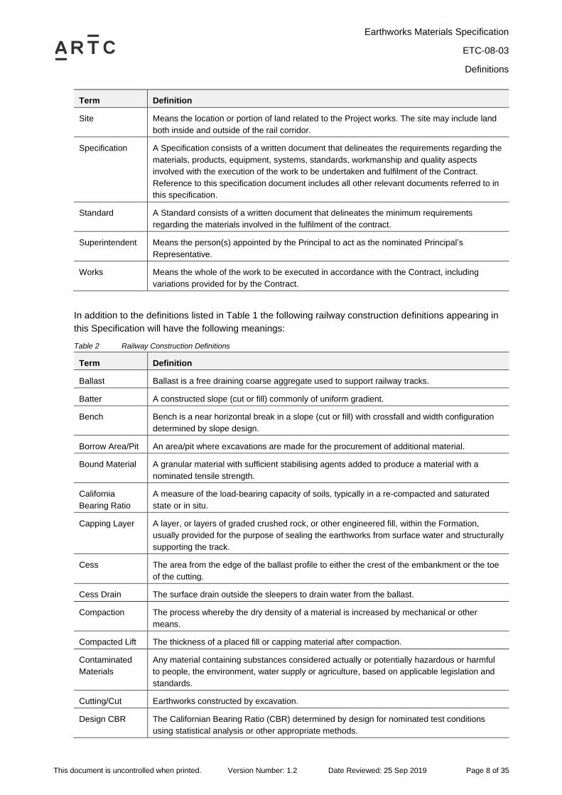
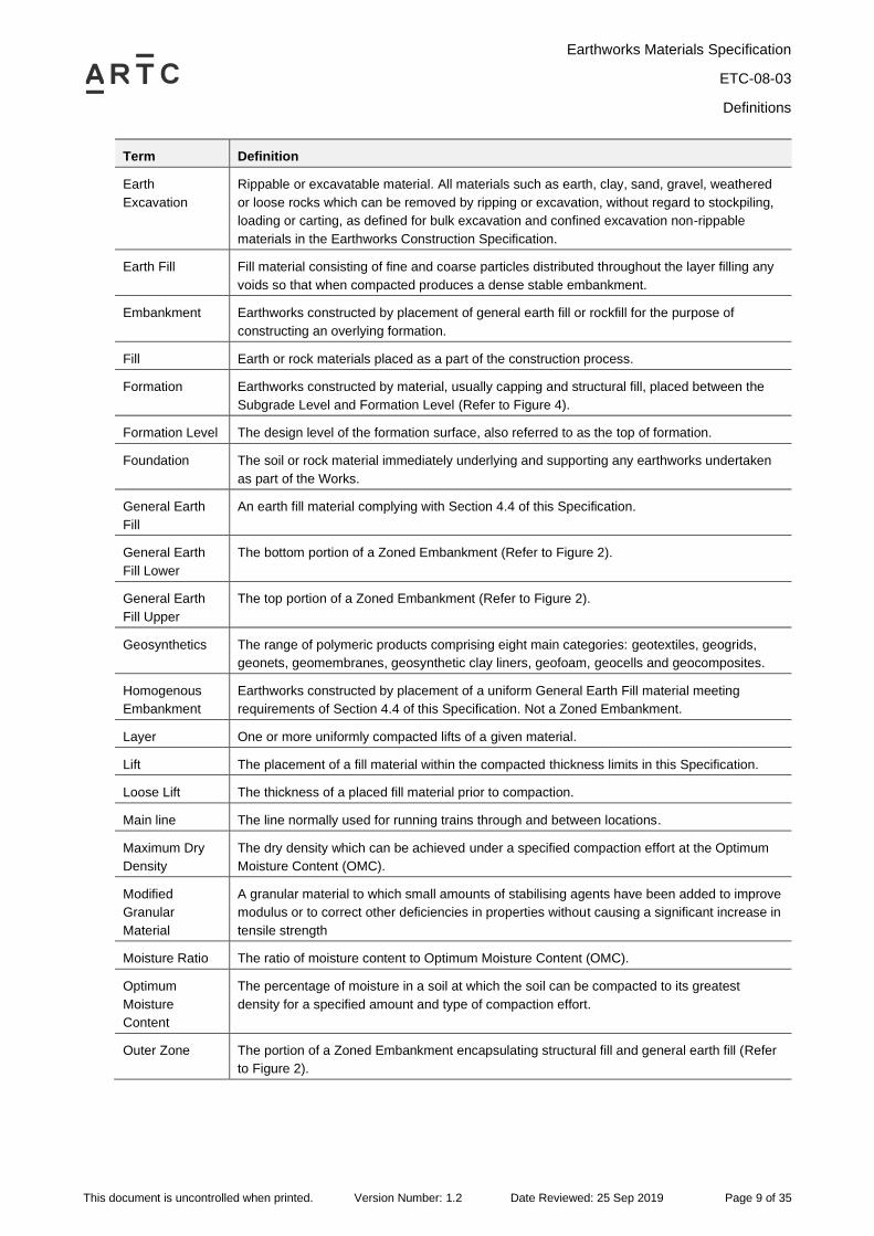
In addition to the definitions listed in Table 1 the following railway construction definitions appearing in
this Specification will have the following meanings:
Table 2 Railway Construction Definitions
Term Definition
Ballast Ballast is a free draining coarse aggregate used to support railway tracks.
Batter A constructed slope (cut or fill) commonly of uniform gradient.
Bench Bench is a near horizontal break in a slope (cut or fill) with crossfall and width configuration
determined by slope design.
Borrow Area/Pit An area/pit where excavations are made for the procurement of additional material.
Bound Material A granular material with sufficient stabilising agents added to produce a material with a
nominated tensile strength.
California
Bearing Ratio
A measure of the load-bearing capacity of soils, typically in a re-compacted and saturated
state or in situ.
Capping Layer A layer, or layers of graded crushed rock, or other engineered fill, within the Formation,
usually provided for the purpose of sealing the earthworks from surface water and structurally
supporting the track.
Cess The area from the edge of the ballast profile to either the crest of the embankment or the toe
of the cutting.
Cess Drain The surface drain outside the sleepers to drain water from the ballast.
Compaction The process whereby the dry density of a material is increased by mechanical or other
means.
Compacted Lift The thickness of a placed fill or capping material after compaction.
Contaminated
Materials
Any material containing substances considered actually or potentially hazardous or harmful
to people, the environment, water supply or agriculture, based on applicable legislation and
standards.
Cutting/Cut Earthworks constructed by excavation.
Design CBR The Californian Bearing Ratio (CBR) determined by design for nominated test conditions
using statistical analysis or other appropriate methods.
Earthworks Materials Specification
ETC-08-03
Definitions
This document is uncontrolled when printed. Version Number: 1.2 Date Reviewed: 25 Sep 2019 Page 9 of 35
Term Definition
Earth
Excavation
Rippable or excavatable material. All materials such as earth, clay, sand, gravel, weathered
or loose rocks which can be removed by ripping or excavation, without regard to stockpiling,
loading or carting, as defined for bulk excavation and confined excavation non-rippable
materials in the Earthworks Construction Specification.
Earth Fill Fill material consisting of fine and coarse particles distributed throughout the layer filling any
voids so that when compacted produces a dense stable embankment.
Embankment Earthworks constructed by placement of general earth fill or rockfill for the purpose of
constructing an overlying formation.
Fill Earth or rock materials placed as a part of the construction process.
Formation Earthworks constructed by material, usually capping and structural fill, placed between the
Subgrade Level and Formation Level (Refer to Figure 4).
Formation Level The design level of the formation surface, also referred to as the top of formation.
Foundation The soil or rock material immediately underlying and supporting any earthworks undertaken
as part of the Works.
General Earth
Fill
An earth fill material complying with Section 4.4 of this Specification.
General Earth
Fill Lower
The bottom portion of a Zoned Embankment (Refer to Figure 2).
General Earth
Fill Upper
The top portion of a Zoned Embankment (Refer to Figure 2).
Geosynthetics The range of polymeric products comprising eight main categories: geotextiles, geogrids,
geonets, geomembranes, geosynthetic clay liners, geofoam, geocells and geocomposites.
Homogenous
Embankment
Earthworks constructed by placement of a uniform General Earth Fill material meeting
requirements of Section 4.4 of this Specification. Not a Zoned Embankment.
Layer One or more uniformly compacted lifts of a given material.
Lift The placement of a fill material within the compacted thickness limits in this Specification.
Loose Lift The thickness of a placed fill material prior to compaction.
Main line The line normally used for running trains through and between locations.
Maximum Dry
Density
The dry density which can be achieved under a specified compaction effort at the Optimum
Moisture Content (OMC).
Modified
Granular
Material
A granular material to which small amounts of stabilising agents have been added to improve
modulus or to correct other deficiencies in properties without causing a significant increase in
tensile strength
Moisture Ratio The ratio of moisture content to Optimum Moisture Content (OMC).
Optimum
Moisture
Content
The percentage of moisture in a soil at which the soil can be compacted to its greatest
density for a specified amount and type of compaction effort.
Outer Zone The portion of a Zoned Embankment encapsulating structural fill and general earth fill (Refer
to Figure 2).
Earthworks Materials Specification
ETC-08-03
Definitions
This document is uncontrolled when printed. Version Number: 1.2 Date Reviewed: 25 Sep 2019 Page 10 of 35
Term Definition
Rockfill A material, meeting the requirements of Section 4.7, which when placed, produces an
embankment deriving its stability from the mechanical interlock of the coarser particles,
rather than from the compaction of finer material around the coarser particles. Rockfill may
contain large open voids.
Select Fill Material for use adjacent to structures or in other distinct applications that require specific
properties defined for that purpose.
Siding A section of railway track, connected to a running line or another siding, on which rolling
stock can be placed clear of the running line and normally used for purposes such as
stabling, loading, rolling stock maintenance or passing of trains.
Stabilisation The permanent physical and chemical alteration of materials to enhance their physical
properties.
Stripped Surface
Level
The ground surface after clearing and grubbing and topsoil stripping operations have been
completed.
Structural Fill
Layer
A layer, or layers of engineered fill, meeting the requirements of Section 4.3 of this
Specification, usually placed to provide a gradational structural support zone between the
Subgrade Level and Capping Layer.
Subgrade Level The finished surface of an embankment or cutting upon which the formation is constructed.
Topsoil The upper most layer of the soil usually dark in colour and rich in organic material.
Track The infrastructure upon which rolling stock travels. Track can be designated as uni-
directional or bi-directional. Track is formed through the combination of rails, rail connectors,
sleepers, ballast, points, crossings, and substitute devices where used. Also referred to as
the Track Structure (Refer to Figure 4).
Unsuitable
Material
All material identified as unsuitable, as defined in Section 4.11, for use as a foundation for
earthworks or structures or for use as fill material in its present position or condition.
Weighted
Plasticity Index
Defined as the value of the Plasticity Index (PI) times the % passing the 0.425 mm sieve.
Zoned
Embankment
An embankment comprised of zones of different types of fill materials (Refer to Figure 2).
The abbreviations listed below where used in the Specification, will have the following meaning:
Table 3 Abbreviations
Abbreviation Meaning
ARTC Australian Rail Track Corporation
AS Australian Standard
BoD Basis of Design
CBR California Bearing Ratio
EOS Equivalent Opening Size
ITP Inspection Test Plan
MDD Maximum Dry Density
MR Moisture Ratio (% of OMC)
NATA National Association of Testing Authorities
Earthworks Materials Specification
ETC-08-03
Definitions
This document is uncontrolled when printed. Version Number: 1.2 Date Reviewed: 25 Sep 2019 Page 11 of 35
Abbreviation Meaning
OMC Optimum Moisture Content
PI Plasticity Index
PQP Project Quality Plan
RMS Roads and Maritime Services - NSW
SMDD Standard Maximum Dry Density
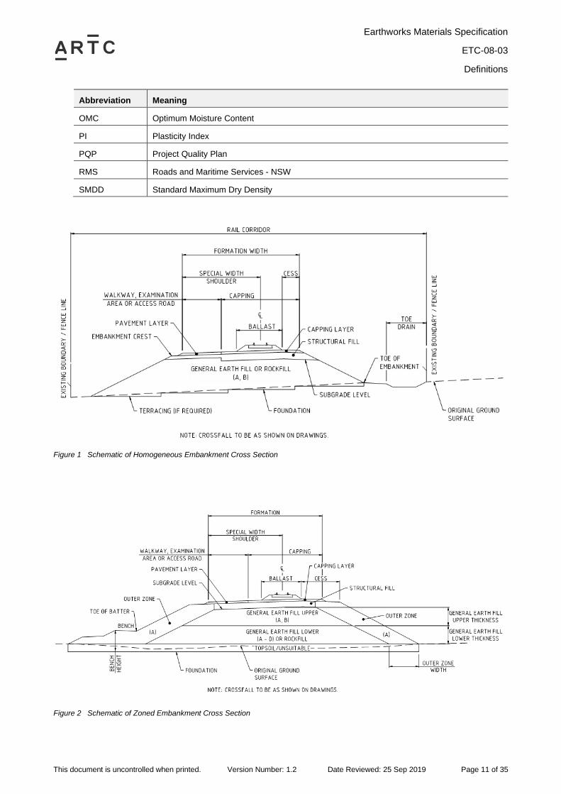
Figure 1 Schematic of Homogeneous Embankment Cross Section
Figure 2 Schematic of Zoned Embankment Cross Section
Earthworks Materials Specification
ETC-08-03
Definitions
This document is uncontrolled when printed. Version Number: 1.2 Date Reviewed: 25 Sep 2019 Page 12 of 35
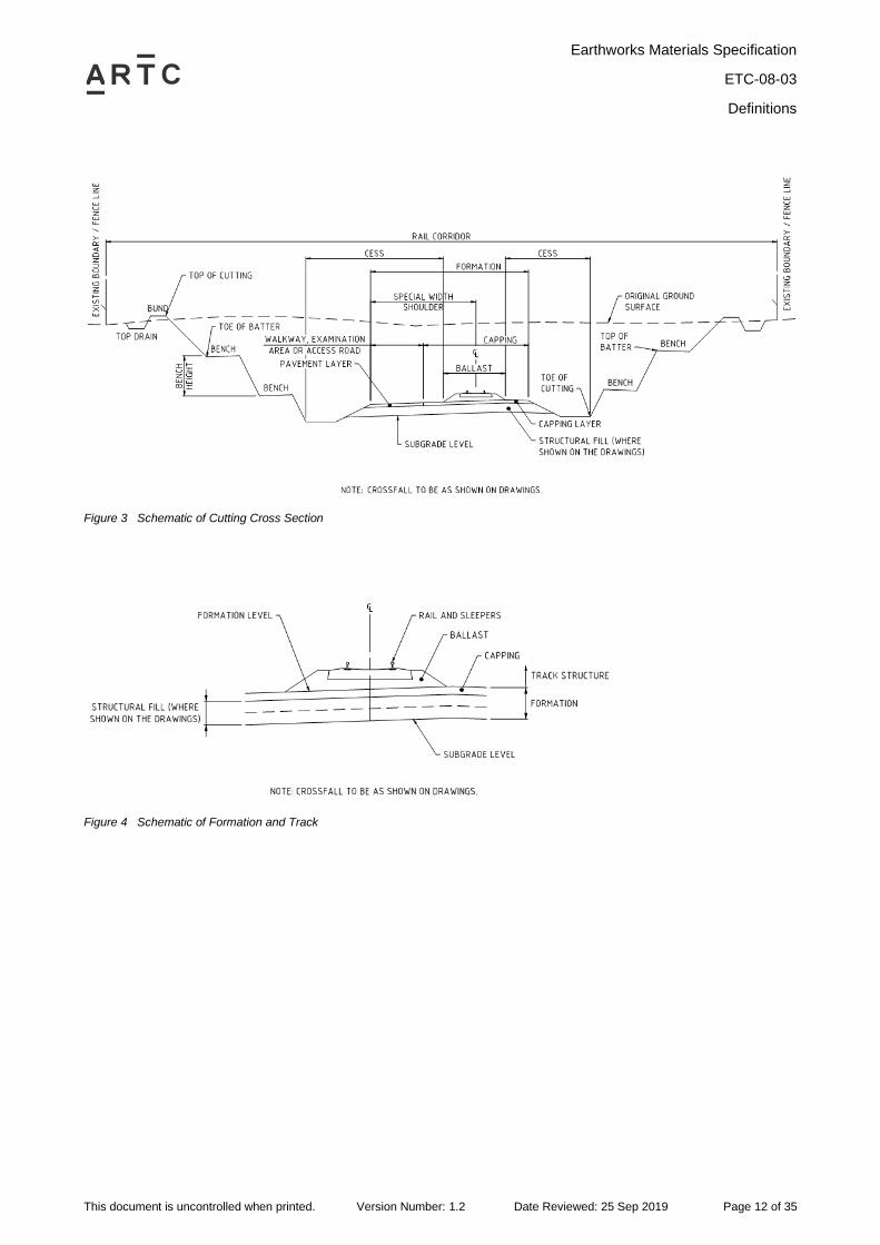
Figure 3 Schematic of Cutting Cross Section
Figure 4 Schematic of Formation and Track
Earthworks Materials Specification
ETC-08-03
Codes and Standards
This document is uncontrolled when printed. Version Number: 1.2 Date Reviewed: 25 Sep 2019 Page 13 of 35
3 Codes and Standards
All design, materials, equipment, workmanship and installations will comply with the latest revision of
the Programme Standards and Specifications, ARTC Engineering Standards, relevant rail authorities
and Australian Standards (AS) relating to the relevant element or component of Works unless otherwise
noted in this Specification.
The following codes and standards apply for the Project, and any discrepancy between standards and
this Specification must be referred to the Superintendent for clarification.
AS1012 Methods of testing concrete
AS1141 Methods for sampling and testing aggregates
AS1289 Methods of testing soil for engineering purposes
AS1672 Building Limes
AS1726 Geotechnical Site Investigations
AS/NZS2041 Buried Corrugate Metal Structures
AS2159 Piling – Design and Installation
AS2758 Aggregates and rock for engineering purposes
AS3706 Geotextiles – Methods of test
AS/NZS3725 Design for installation of buried concrete pipes
AS3972 General purpose and blended cements
AS4133 Methods of testing rocks for engineering purposes
AS4489 Test Methods for Limes and Limestones
AS5101 Methods for preparation and testing of stabilised materials
AS7638 Railway Earthworks
The latest ARTC Engineering Standards and Codes of Practice are available from www.artc.com.au/.
Changes to the ARTC Specifications relating to this Specification are listed in Appendix B.
Earthworks Materials Specification
ETC-08-03
Earthworks Materials
This document is uncontrolled when printed. Version Number: 1.2 Date Reviewed: 25 Sep 2019 Page 14 of 35
4 Earthworks Materials
4.1 General
The Contractor must:
• Only use earthworks materials approved for use by the Superintendent. Earthworks materials may
include appropriately classified waste material in accordance with relevant state authority
environmental requirements;
• Stockpile, test (to Australian Standards) and gain approval of all materials in accordance with their
classification prior to placement;
• Ensure all general earth fill materials have a uniform grading and must not be gap graded
between the coarse limit of the grading envelope to the fine limit of the grading envelope, or vice
versa;
• Undertake appropriate testing of all construction material sources to confirm compliance to this
Specification;
• Evaluate the suitability of non-potable water by field and laboratory testing at the discretion of and
approved by the Superintendent; and
• Ensure saline water with chemical composition exceeding the limits specified in AS2159 is not
used in fill material where steel elements or steel reinforced concrete are buried, or where
vegetation is to be established.
Classification conformance criteria must be determined by sampling of sources, stockpiles and Lots.
Placement conformance criteria must be determined by appropriate test methods post placement.
Embankments shall be comprised of materials derived from excavated cuts, borrow pits, quarries and
other approved sources.
Test method frequencies presented in the following tables may be varied in accordance with Section
6.2.
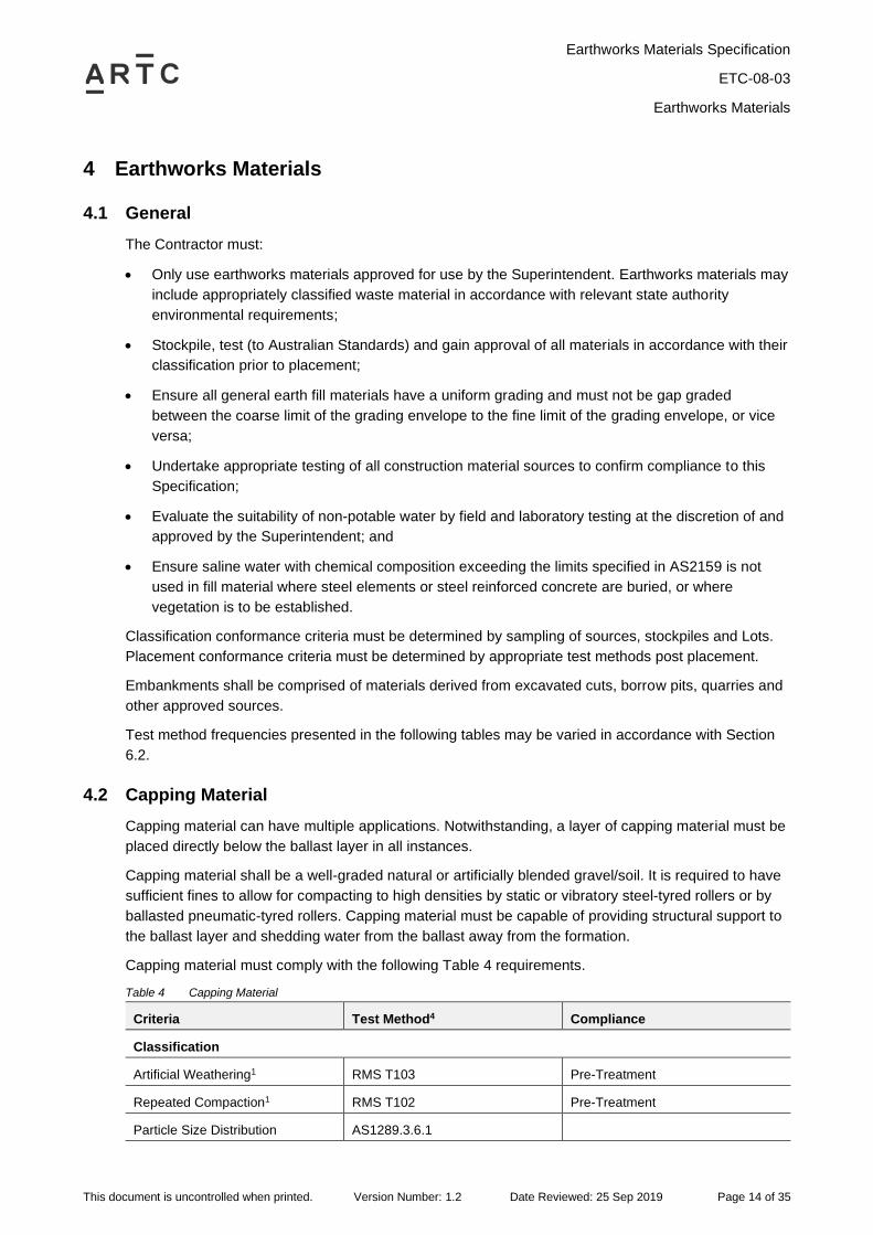
4.2 Capping Material
Capping material can have multiple applications. Notwithstanding, a layer of capping material must be
placed directly below the ballast layer in all instances.
Capping material shall be a well-graded natural or artificially blended gravel/soil. It is required to have
sufficient fines to allow for compacting to high densities by static or vibratory steel-tyred rollers or by
ballasted pneumatic-tyred rollers. Capping material must be capable of providing structural support to
the ballast layer and shedding water from the ballast away from the formation.
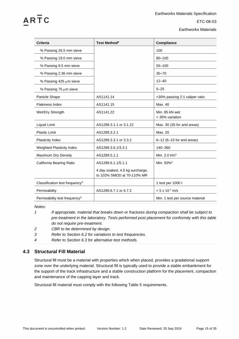
Capping material must comply with the following Table 4 requirements.
Table 4 Capping Material
Criteria Test Method4 Compliance
Classification
Artificial Weathering1 RMS T103 Pre-Treatment
Repeated Compaction1 RMS T102 Pre-Treatment
Particle Size Distribution AS1289.3.6.1
Earthworks Materials Specification
ETC-08-03
Earthworks Materials
This document is uncontrolled when printed. Version Number: 1.2 Date Reviewed: 25 Sep 2019 Page 15 of 35
Criteria Test Method4 Compliance
% Passing 26.5 mm sieve 100
% Passing 19.0 mm sieve 80–100
% Passing 9.5 mm sieve 55–100
% Passing 2.36 mm sieve 30–70
% Passing 425 m sieve 12–40
% Passing 75 m sieve 5–25
Particle Shape AS1141.14 <30% passing 2:1 caliper ratio
Flakiness Index AS1141.15 Max. 40
Wet/Dry Strength AS1141.22 Min. 85 kN wet
< 35% variation
Liquid Limit AS1289.3.1.1 or 3.1.22 Max. 30 (35 for arid areas)
Plastic Limit AS1289.3.2.1 Max. 20
Plasticity Index AS1289.3.3.1 or 3.3.2 6–12 (6–15 for arid areas)
Weighted Plasticity Index AS1289.3.6.1/3.3.1 140–360
Maximum Dry Density AS1289.5.1.1 Min. 2.0 t/m3
California Bearing Ratio AS1289.6.1.1/5.1.1
4 day soaked, 4.5 kg surcharge,
to 102% SMDD at 70-110% MR
Min. 50%2
Classification test frequency3 1 test per 1000 t
Permeability AS1289.6.7.1 or 6.7.2 < 5 x 10⁻⁷ m/s
Permeability test frequency3 Min. 1 test per source material
Notes:
1 If appropriate, material that breaks down or fractures during compaction shall be subject to
pre-treatment in the laboratory. Tests performed post placement for conformity with this table
do not require pre-treatment.
2 CBR to be determined by design.
3 Refer to Section 6.2 for variations to test frequencies.
4 Refer to Section 6.3 for alternative test methods.
4.3 Structural Fill Material
Structural fill must be a material with properties which when placed, provides a gradational support
zone over the underlying material. Structural fill is typically used to provide a stable embankment for
the support of the track infrastructure and a stable construction platform for the placement, compaction
and maintenance of the capping layer and track.
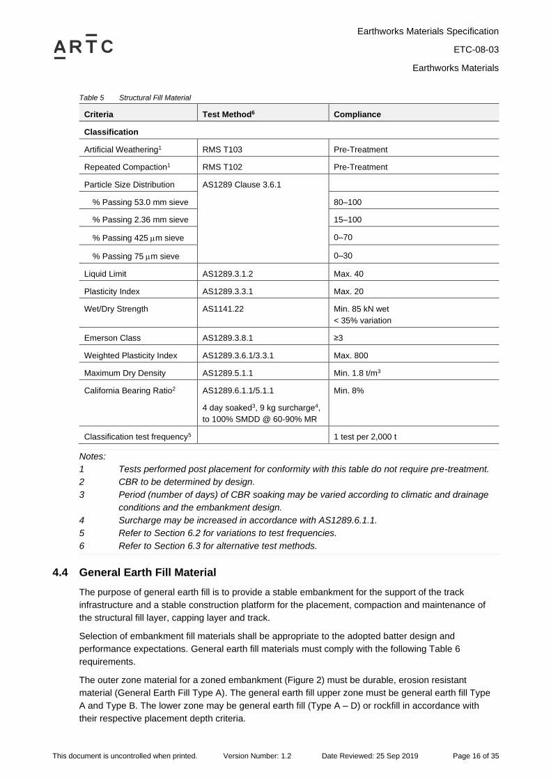
Structural fill material must comply with the following Table 5 requirements.
Earthworks Materials Specification
ETC-08-03
Earthworks Materials
This document is uncontrolled when printed. Version Number: 1.2 Date Reviewed: 25 Sep 2019 Page 16 of 35
Table 5 Structural Fill Material
Criteria Test Method6 Compliance
Classification
Artificial Weathering1 RMS T103 Pre-Treatment
Repeated Compaction1 RMS T102 Pre-Treatment
Particle Size Distribution AS1289 Clause 3.6.1
% Passing 53.0 mm sieve 80–100
% Passing 2.36 mm sieve 15–100
% Passing 425 m sieve 0–70
% Passing 75 m sieve 0–30
Liquid Limit AS1289.3.1.2 Max. 40
Plasticity Index AS1289.3.3.1 Max. 20
Wet/Dry Strength AS1141.22 Min. 85 kN wet
< 35% variation
Emerson Class AS1289.3.8.1 ≥3
Weighted Plasticity Index AS1289.3.6.1/3.3.1 Max. 800
Maximum Dry Density AS1289.5.1.1 Min. 1.8 t/m3
California Bearing Ratio2 AS1289.6.1.1/5.1.1
4 day soaked3, 9 kg surcharge4,
to 100% SMDD @ 60-90% MR
Min. 8%
Classification test frequency5 1 test per 2,000 t
Notes:
1 Tests performed post placement for conformity with this table do not require pre-treatment.
2 CBR to be determined by design.
3 Period (number of days) of CBR soaking may be varied according to climatic and drainage
conditions and the embankment design.
4 Surcharge may be increased in accordance with AS1289.6.1.1.
5 Refer to Section 6.2 for variations to test frequencies.
6 Refer to Section 6.3 for alternative test methods.
4.4 General Earth Fill Material
The purpose of general earth fill is to provide a stable embankment for the support of the track
infrastructure and a stable construction platform for the placement, compaction and maintenance of
the structural fill layer, capping layer and track.
Selection of embankment fill materials shall be appropriate to the adopted batter design and
performance expectations. General earth fill materials must comply with the following Table 6
requirements.
The outer zone material for a zoned embankment (Figure 2) must be durable, erosion resistant
material (General Earth Fill Type A). The general earth fill upper zone must be general earth fill Type
A and Type B. The lower zone may be general earth fill (Type A – D) or rockfill in accordance with
their respective placement depth criteria.
Earthworks Materials Specification
ETC-08-03
Earthworks Materials
This document is uncontrolled when printed. Version Number: 1.2 Date Reviewed: 25 Sep 2019 Page 17 of 35
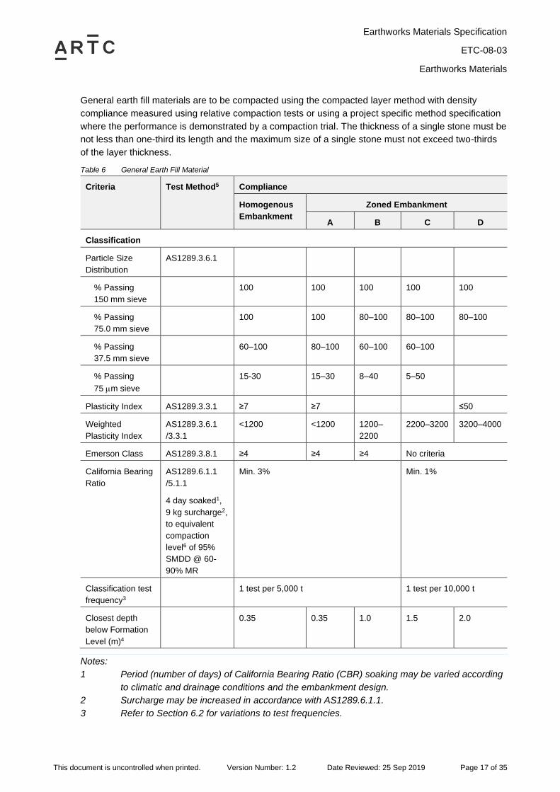
General earth fill materials are to be compacted using the compacted layer method with density
compliance measured using relative compaction tests or using a project specific method specification
where the performance is demonstrated by a compaction trial. The thickness of a single stone must be
not less than one-third its length and the maximum size of a single stone must not exceed two-thirds
of the layer thickness.
Table 6 General Earth Fill Material
Criteria Test Method5 Compliance
Homogenous
Embankment
Zoned Embankment
A B C D
Classification
Particle Size
Distribution
AS1289.3.6.1
% Passing
150 mm sieve
100 100 100 100 100
% Passing
75.0 mm sieve
100 100 80–100 80–100 80–100
% Passing
37.5 mm sieve
60–100 80–100 60–100 60–100
% Passing
75 m sieve
15-30 15–30 8–40 5–50
Plasticity Index AS1289.3.3.1 ≥7 ≥7 ≤50
Weighted
Plasticity Index
AS1289.3.6.1
/3.3.1
<1200 <1200 1200–
2200
2200–3200 3200–4000
Emerson Class AS1289.3.8.1 ≥4 ≥4 ≥4 No criteria
California Bearing
Ratio
AS1289.6.1.1
/5.1.1
4 day soaked1,
9 kg surcharge2,
to equivalent
compaction
level6 of 95%
SMDD @ 60-
90% MR
Min. 3% Min. 1%
Classification test
frequency3
1 test per 5,000 t 1 test per 10,000 t
Closest depth
below Formation
Level (m)4
0.35 0.35 1.0 1.5 2.0
Notes:
1 Period (number of days) of California Bearing Ratio (CBR) soaking may be varied according
to climatic and drainage conditions and the embankment design.
2 Surcharge may be increased in accordance with AS1289.6.1.1.
3 Refer to Section 6.2 for variations to test frequencies.
Earthworks Materials Specification
ETC-08-03
Earthworks Materials
This document is uncontrolled when printed. Version Number: 1.2 Date Reviewed: 25 Sep 2019 Page 18 of 35
4 Closest depth below Formation Level may be varied by geotechnical design and supporting
documentation.
5 Refer to Section 6.3 for alternative test methods.
6 Equivalent Compaction Level is provided as coarse materials may not be able to be tested
using standard test methods, alternative test methods (Note 5) are to be nominated to
demonstrate general compliance to these compaction levels.
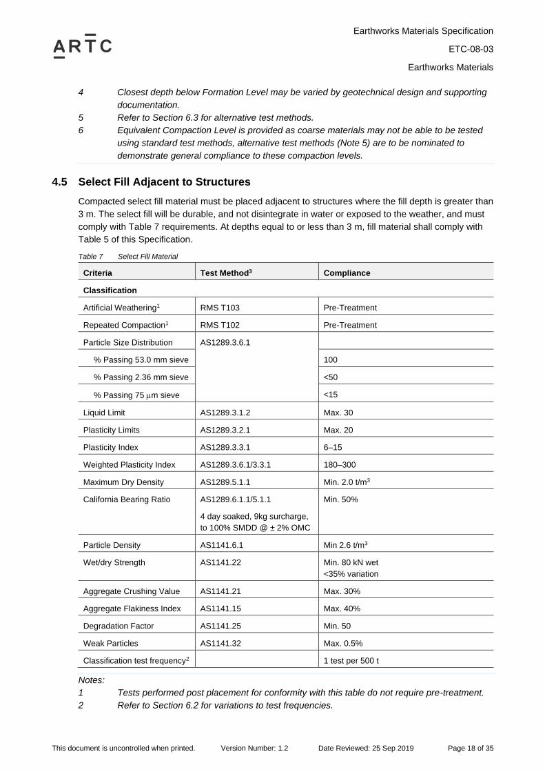
4.5 Select Fill Adjacent to Structures
Compacted select fill material must be placed adjacent to structures where the fill depth is greater than
3 m. The select fill will be durable, and not disintegrate in water or exposed to the weather, and must
comply with Table 7 requirements. At depths equal to or less than 3 m, fill material shall comply with
Table 5 of this Specification.
Table 7 Select Fill Material
Criteria Test Method3 Compliance
Classification
Artificial Weathering1 RMS T103 Pre-Treatment
Repeated Compaction1 RMS T102 Pre-Treatment
Particle Size Distribution AS1289.3.6.1
% Passing 53.0 mm sieve 100
% Passing 2.36 mm sieve <50
% Passing 75 m sieve <15
Liquid Limit AS1289.3.1.2 Max. 30
Plasticity Limits AS1289.3.2.1 Max. 20
Plasticity Index AS1289.3.3.1 6–15
Weighted Plasticity Index AS1289.3.6.1/3.3.1 180–300
Maximum Dry Density AS1289.5.1.1 Min. 2.0 t/m3
California Bearing Ratio AS1289.6.1.1/5.1.1
4 day soaked, 9kg surcharge,
to 100% SMDD @ ± 2% OMC
Min. 50%
Particle Density AS1141.6.1 Min 2.6 t/m3
Wet/dry Strength AS1141.22 Min. 80 kN wet
<35% variation
Aggregate Crushing Value AS1141.21 Max. 30%
Aggregate Flakiness Index AS1141.15 Max. 40%
Degradation Factor AS1141.25 Min. 50
Weak Particles AS1141.32 Max. 0.5%
Classification test frequency2 1 test per 500 t
Notes:
1 Tests performed post placement for conformity with this table do not require pre-treatment.
2 Refer to Section 6.2 for variations to test frequencies.
Earthworks Materials Specification
ETC-08-03
Earthworks Materials
This document is uncontrolled when printed. Version Number: 1.2 Date Reviewed: 25 Sep 2019 Page 19 of 35
3 Refer to Section 6.3 for alternative test methods.
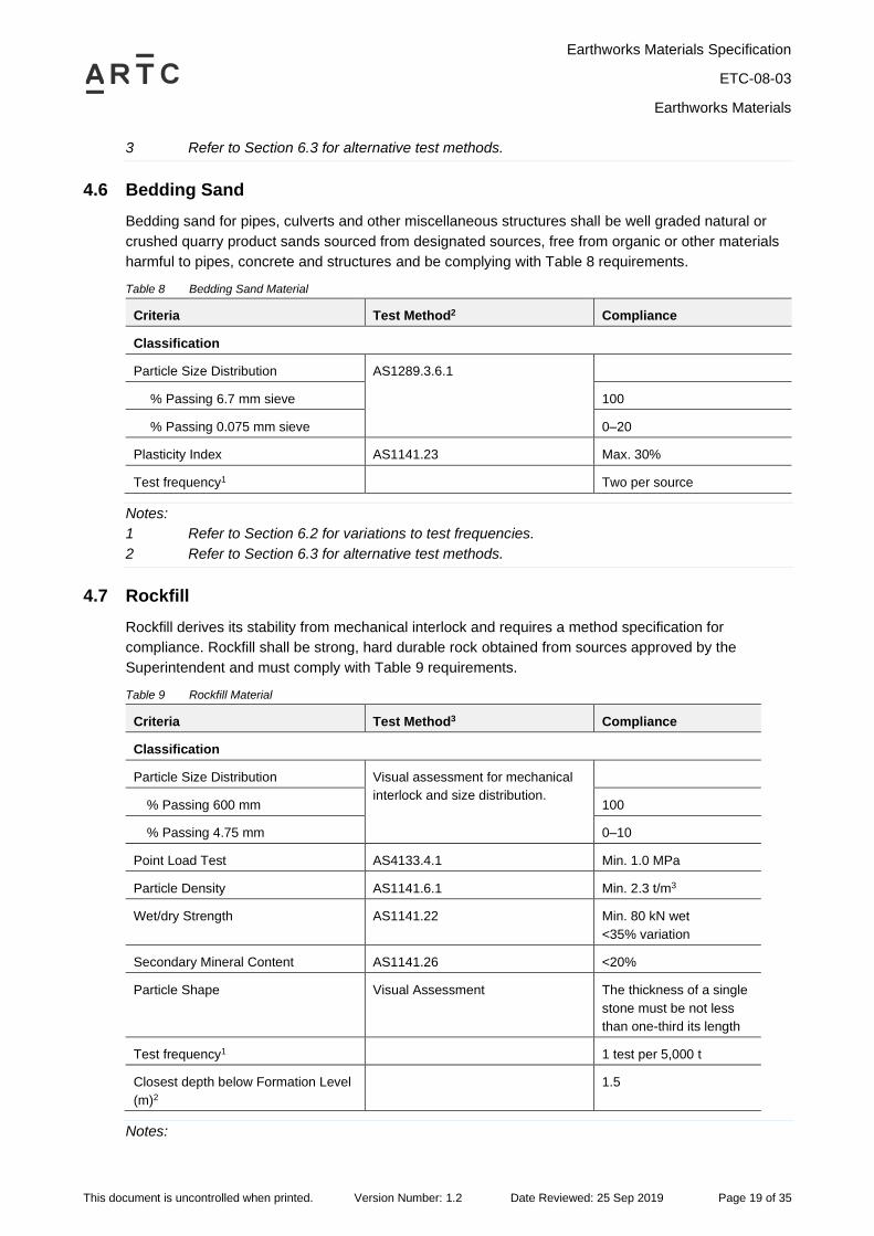
4.6 Bedding Sand
Bedding sand for pipes, culverts and other miscellaneous structures shall be well graded natural or
crushed quarry product sands sourced from designated sources, free from organic or other materials
harmful to pipes, concrete and structures and be complying with Table 8 requirements.
Table 8 Bedding Sand Material
Criteria Test Method2 Compliance
Classification
Particle Size Distribution AS1289.3.6.1
% Passing 6.7 mm sieve 100
% Passing 0.075 mm sieve 0–20
Plasticity Index AS1141.23 Max. 30%
Test frequency1 Two per source
Notes:
1 Refer to Section 6.2 for variations to test frequencies.
2 Refer to Section 6.3 for alternative test methods.
4.7 Rockfill
Rockfill derives its stability from mechanical interlock and requires a method specification for
compliance. Rockfill shall be strong, hard durable rock obtained from sources approved by the
Superintendent and must comply with Table 9 requirements.
Table 9 Rockfill Material
Criteria Test Method3 Compliance
Classification
Particle Size Distribution Visual assessment for mechanical
interlock and size distribution.
% Passing 600 mm 100
% Passing 4.75 mm 0–10
Point Load Test AS4133.4.1 Min. 1.0 MPa
Particle Density AS1141.6.1 Min. 2.3 t/m3
Wet/dry Strength AS1141.22 Min. 80 kN wet
<35% variation
Secondary Mineral Content AS1141.26 <20%
Particle Shape Visual Assessment The thickness of a single
stone must be not less
than one-third its length
Test frequency1 1 test per 5,000 t
Closest depth below Formation Level
(m)2
1.5
Notes:
Earthworks Materials Specification
ETC-08-03
Earthworks Materials
This document is uncontrolled when printed. Version Number: 1.2 Date Reviewed: 25 Sep 2019 Page 20 of 35
1 Refer to Section 6.2 for variations to test frequencies.
2 Closest depth below Formation Level may be varied by geotechnical design and supporting
documentation.
3 Refer to Section 6.3 for alternative test methods.
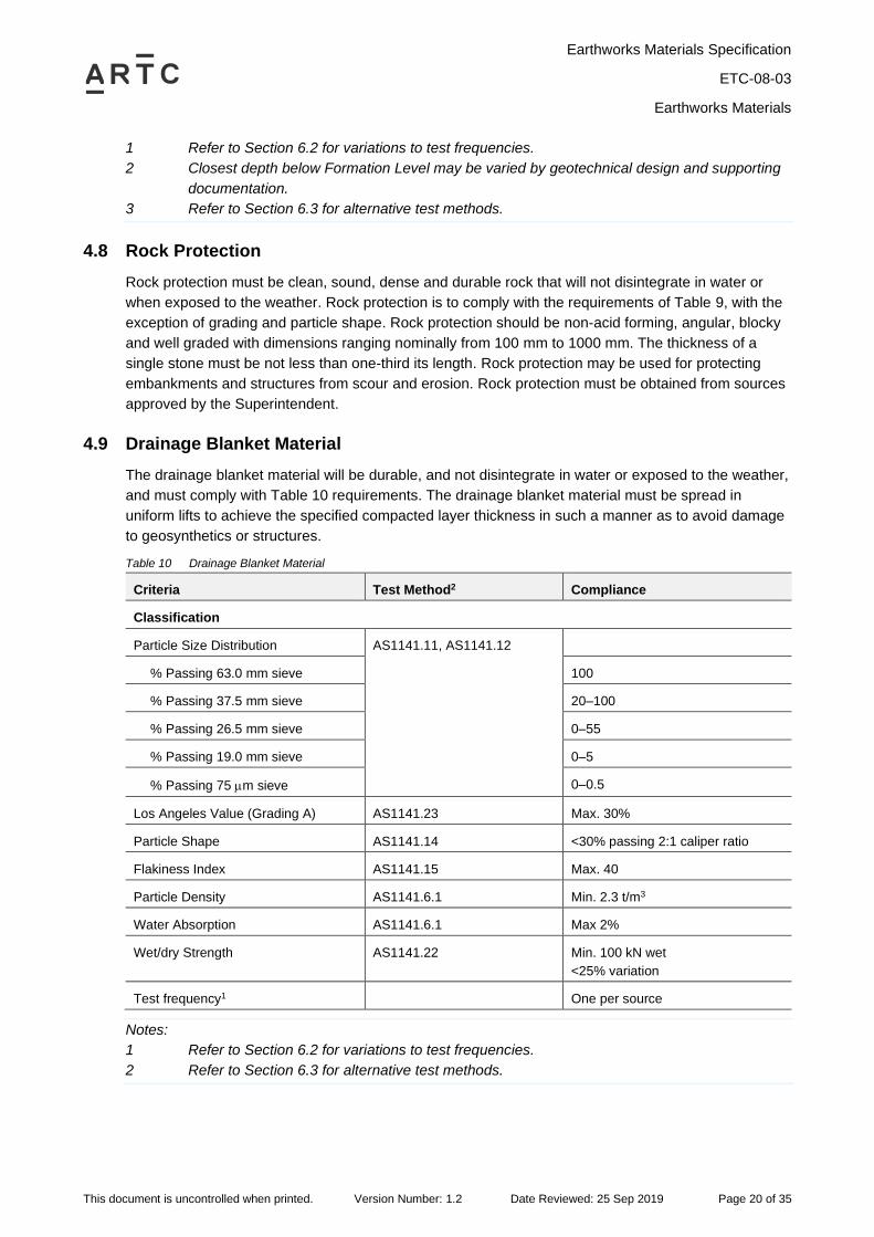
4.8 Rock Protection
Rock protection must be clean, sound, dense and durable rock that will not disintegrate in water or
when exposed to the weather. Rock protection is to comply with the requirements of Table 9, with the
exception of grading and particle shape. Rock protection should be non-acid forming, angular, blocky
and well graded with dimensions ranging nominally from 100 mm to 1000 mm. The thickness of a
single stone must be not less than one-third its length. Rock protection may be used for protecting
embankments and structures from scour and erosion. Rock protection must be obtained from sources
approved by the Superintendent.
4.9 Drainage Blanket Material
The drainage blanket material will be durable, and not disintegrate in water or exposed to the weather,
and must comply with Table 10 requirements. The drainage blanket material must be spread in
uniform lifts to achieve the specified compacted layer thickness in such a manner as to avoid damage
to geosynthetics or structures.
Table 10 Drainage Blanket Material
Criteria Test Method2 Compliance
Classification
Particle Size Distribution AS1141.11, AS1141.12
% Passing 63.0 mm sieve 100
% Passing 37.5 mm sieve 20–100
% Passing 26.5 mm sieve 0–55
% Passing 19.0 mm sieve 0–5
% Passing 75 m sieve 0–0.5
Los Angeles Value (Grading A) AS1141.23 Max. 30%
Particle Shape AS1141.14 <30% passing 2:1 caliper ratio
Flakiness Index AS1141.15 Max. 40
Particle Density AS1141.6.1 Min. 2.3 t/m3
Water Absorption AS1141.6.1 Max 2%
Wet/dry Strength AS1141.22 Min. 100 kN wet
<25% variation
Test frequency1 One per source
Notes:
1 Refer to Section 6.2 for variations to test frequencies.
2 Refer to Section 6.3 for alternative test methods.
Earthworks Materials Specification
ETC-08-03
Earthworks Materials
This document is uncontrolled when printed. Version Number: 1.2 Date Reviewed: 25 Sep 2019 Page 21 of 35
4.10 Other Drainage Materials
All other drainage materials, including controlled low strength materials (CLSM, Appendix A of
AS3725), filter material and lean mix concrete (5 MPa concrete), must be specified in accordance with
the relevant Australian Standards (such as AS2041 and AS3725).
4.11 Unsuitable Material
4.11.1 General
The following materials are deemed unsuitable materials and must not be used in the constructed
works unless otherwise treated and approved by the Superintendent in accordance with the
Earthworks Construction Specification.
4.11.2 Inherently Unsuitable
Inherently unsuitable materials are:
• Materials susceptible to piping, such as fine single sized sand, windblown sand and non-
cohesive silt;
• Material containing high organic content, vegetable matter, large rocks, gypsum, debris, or
other materials that could cause the fill not to compact to specification;
• Organic soils with Unified Soil Classifications of Pt, OH, or OL (AS1726); or
• Contaminated materials or prescribed waste materials as classified by relevant legislation,
with the exception of materials deemed suitable for reuse from existing formation.
4.11.3 Unsuitable Materials by Virtue of Position
Unsuitable materials by virtue of position are:
• Soil having insufficient strength to carry the loads that will be superimposed on the
completed fill without excessive settlement, swell, erosion or loss of stability.
4.11.4 Unsuitable by Moisture Content
Unsuitable materials by moisture content will be materials not meeting moisture requirements for
compaction in accordance with the Earthworks Construction Specification.
4.12 Stabilised Material
The Contractor must develop a Project Specific Specification for the use of stabilised materials which
includes results and details of laboratory testing (test methods to demonstrate short and long term
performance criteria), stabilisation method (plant mixed or in situ), stabilisation trial sections and
Quality Assurance / Quality Control procedures to meet requirements of this Specification and the
Earthworks Construction Specification. Alternative test methods (Section 6.3) for stabilised material
may be nominated by the Contractor as part of the Project Quality Plan (PQP).
The Project Specific Specification for stabilisation will be submitted to the Superintendent for approval
prior to any stabilising work commencing.
Materials may be chemically stabilised by an approved binder(s) to produce a stabilised material. The
design criteria for stabilised fill must be determined based on meeting the long term design
performance criteria. Chemical stabilisation can include lime, cement, bitumen, polymers or other
Earthworks Materials Specification
ETC-08-03
Earthworks Materials
This document is uncontrolled when printed. Version Number: 1.2 Date Reviewed: 25 Sep 2019 Page 22 of 35
proprietary products. In addition to CBR strength requirements, Uniaxial Compressive Strength
(AS1141.51 or AS5101.4) shall be <1.5 MPa at minimum 28 days curing and 4 hour soak using
standard compactive effort to prevent cracking and preclude bound materials from within the
formation.
The stabilising agent must be determined based on laboratory mix design testing to confirm the
percentage of binders added to a material to meet the specified design criteria.
Bulk lime for stabilisation must comply with requirements of hydrated or quick lime (AS1672) with a
minimum Calcium Hydroxide (Ca(OH)2) of 85% (AS4489.6.1).
Bulk cement for stabilisation must comply with requirements of AS3972, Type GP (General Purpose)
or GB (General Blended) cement.
Water used for stabilisation shall be of potable standard unless the chemical composition of non-
potable water is demonstrated to not effect stabilisation.
Earthworks Materials Specification
ETC-08-03
Geotextiles
This document is uncontrolled when printed. Version Number: 1.2 Date Reviewed: 25 Sep 2019 Page 23 of 35
5 Geotextiles
5.1 General
The requirements of this section are applicable to geotextiles for use as separation or filtration
elements in earthworks.
Unless specified otherwise on the Drawings, geotextiles shall meet the following requirements:
• The fibres of the geotextile and thread used in joining lengths shall consist of long chain synthetic
polymers composed of at least 95% by mass of polyolefins or polyesters;
• The geotextile filaments shall be rot-proof, chemically stable and shall have low water
absorbency;
• Filaments shall resist delamination and maintain their relative dimensional stability in the
geotextile;
• Non-woven geotextiles shall have filaments bonded by needle punching, heat or chemical
bonding processes;
• Woven geotextiles shall have filaments interlaced in two sets, mutually at right angles. One set
shall be parallel to the longitudinal direction of the geotextile;
• Geotextiles shall be free of any flaws which may have an adverse effect on the physical and
mechanical properties of the geotextile;
• Geotextiles shall be stabilised against ultraviolet radiation such that when tested in accordance
with AS 3706.11 they shall have retained strength of at least 50% after 672 hours of test
exposure. A certificate not more than a year old shall be provided by the manufacturer; and
• Testing of geotextiles shall be undertaken using test methods in accordance with AS3706.
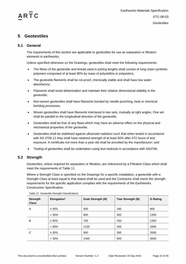
5.2 Strength
Geotextiles, where required for separation or filtration, are referenced by a Filtration Class which shall
meet the requirements of Table 11.
Where a Strength Class is specified on the Drawings for a specific installation, a geotextile with a
Strength Class at least equal to that stated shall be used and the Contractor shall check the strength
requirements for the specific application complies with the requirements of the Earthworks
Construction Specification.
Table 11 Geotextile Strength Classifications
Strength
Class
Elongation1 Grab Strength (N) Tear Strength (N) G Rating
A ≥ 30% 500 180 900
< 30% 800 300 1350
B ≥ 30% 700 250 1350
< 30% 1100 400 2000
C ≥ 30% 900 350 2000
< 30% 1400 500 3000
Earthworks Materials Specification
ETC-08-03
Geotextiles
This document is uncontrolled when printed. Version Number: 1.2 Date Reviewed: 25 Sep 2019 Page 24 of 35
Strength
Class
Elongation1 Grab Strength (N) Tear Strength (N) G Rating
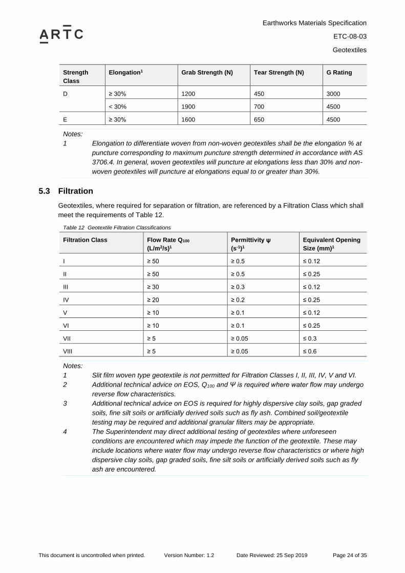
D ≥ 30% 1200 450 3000
< 30% 1900 700 4500
E ≥ 30% 1600 650 4500
Notes:
1 Elongation to differentiate woven from non-woven geotextiles shall be the elongation % at
puncture corresponding to maximum puncture strength determined in accordance with AS
3706.4. In general, woven geotextiles will puncture at elongations less than 30% and non-
woven geotextiles will puncture at elongations equal to or greater than 30%.
5.3 Filtration
Geotextiles, where required for separation or filtration, are referenced by a Filtration Class which shall
meet the requirements of Table 12.
Table 12 Geotextile Filtration Classifications
Filtration Class Flow Rate Q100
(L/m2/s)1
Permittivity ψ
(s-1)1
Equivalent Opening
Size (mm)1
I ≥ 50 ≥ 0.5 ≤ 0.12
II ≥ 50 ≥ 0.5 ≤ 0.25
III ≥ 30 ≥ 0.3 ≤ 0.12
IV ≥ 20 ≥ 0.2 ≤ 0.25
V ≥ 10 ≥ 0.1 ≤ 0.12
VI ≥ 10 ≥ 0.1 ≤ 0.25
VII ≥ 5 ≥ 0.05 ≤ 0.3
VIII ≥ 5 ≥ 0.05 ≤ 0.6
Notes:
1 Slit film woven type geotextile is not permitted for Filtration Classes I, II, III, IV, V and VI.
2 Additional technical advice on EOS, Q100 and Ψ is required where water flow may undergo
reverse flow characteristics.
3 Additional technical advice on EOS is required for highly dispersive clay soils, gap graded
soils, fine silt soils or artificially derived soils such as fly ash. Combined soil/geotextile
testing may be required and additional granular filters may be appropriate.
4 The Superintendent may direct additional testing of geotextiles where unforeseen
conditions are encountered which may impede the function of the geotextile. These may
include locations where water flow may undergo reverse flow characteristics or where high
dispersive clay soils, gap graded soils, fine silt soils or artificially derived soils such as fly
ash are encountered.
Earthworks Materials Specification
ETC-08-03
Quality Plan
This document is uncontrolled when printed. Version Number: 1.2 Date Reviewed: 25 Sep 2019 Page 25 of 35
6 Quality Plan
6.1 Contractor’s Project Quality Plan
The Contractor’s PQP must detail how the Contractor will manage, test and control the quality of the
materials under this Specification. The Contractor may develop appropriate statistical techniques to
support any request to the Superintendent for variance in the number of samples per Lot or minimum
testing frequency for the materials as specified in this Specification using the method for statistical
analysis presented in the Earthworks Construction Specification.
All materials shall be tested in accordance with Australian Standards and the Earthworks Construction
Specification. Samples of material proposed for use must be tested and results considered in the final
selection of material and its use within the track formation.
6.2 Variation of Testing Frequencies
If consistent test results can be demonstrated, the Contractor may apply to the Superintendent for a
reduction in test lot/frequency for that particular quality control test method. The frequency of testing
may be increased at the discretion of the Superintendent if the test results demonstrate a high degree
of variability which could affect the design assumptions or the quality of the completed construction.
Statistical analysis and criteria for reducing compliance testing must be in accordance with the
Programme Quality Plan.
6.3 Alternative Test Methods
Alternative test methods may be proposed by the Contractor to confirm the parameters of the
earthworks materials, formation and subgrade materials during construction.
The Contractor must seek approval from the Superintendent prior to using any alternative test
methods, providing a detailed report on trials conducted using the alternative test methods and
correlation factors to the compliance test requirements of Section 4. The report must also include
statistical analysis and criteria for reducing compliance testing, in accordance with the Programme
Quality Plan. The Contractor must document the alternative test methods in a Project Specific
Specification and append to this Specification. The Project Specific Specification must be approved by
the Superintendent.
Earthworks Materials Specification
ETC-08-03
Appendix A – Specification Variation Compliance Forms
This document is uncontrolled when printed. Version Number: 1.2 Date Reviewed: 25 Sep 2019 Page 26 of 35
Appendix A – Specification Variation Compliance Forms
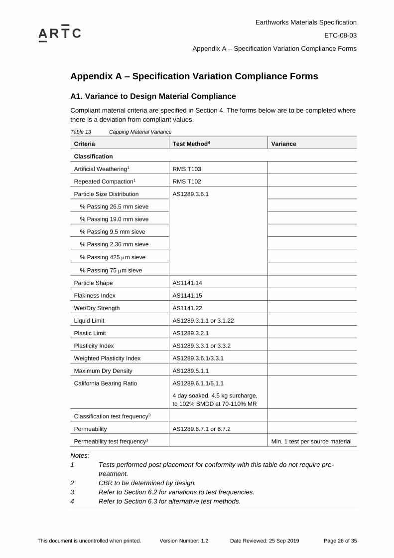
A1. Variance to Design Material Compliance
Compliant material criteria are specified in Section 4. The forms below are to be completed where
there is a deviation from compliant values.
Table 13 Capping Material Variance
Criteria Test Method4 Variance
Classification
Artificial Weathering1 RMS T103
Repeated Compaction1 RMS T102
Particle Size Distribution AS1289.3.6.1
% Passing 26.5 mm sieve
% Passing 19.0 mm sieve
% Passing 9.5 mm sieve
% Passing 2.36 mm sieve
% Passing 425 m sieve
% Passing 75 m sieve
Particle Shape AS1141.14
Flakiness Index AS1141.15
Wet/Dry Strength AS1141.22
Liquid Limit AS1289.3.1.1 or 3.1.22
Plastic Limit AS1289.3.2.1
Plasticity Index AS1289.3.3.1 or 3.3.2
Weighted Plasticity Index AS1289.3.6.1/3.3.1
Maximum Dry Density AS1289.5.1.1
California Bearing Ratio AS1289.6.1.1/5.1.1
4 day soaked, 4.5 kg surcharge,
to 102% SMDD at 70-110% MR
Classification test frequency3
Permeability AS1289.6.7.1 or 6.7.2
Permeability test frequency3 Min. 1 test per source material
Notes:
1 Tests performed post placement for conformity with this table do not require pre-
treatment.
2 CBR to be determined by design.
3 Refer to Section 6.2 for variations to test frequencies.
4 Refer to Section 6.3 for alternative test methods.
Earthworks Materials Specification
ETC-08-03
Appendix A – Specification Variation Compliance Forms
This document is uncontrolled when printed. Version Number: 1.2 Date Reviewed: 25 Sep 2019 Page 27 of 35
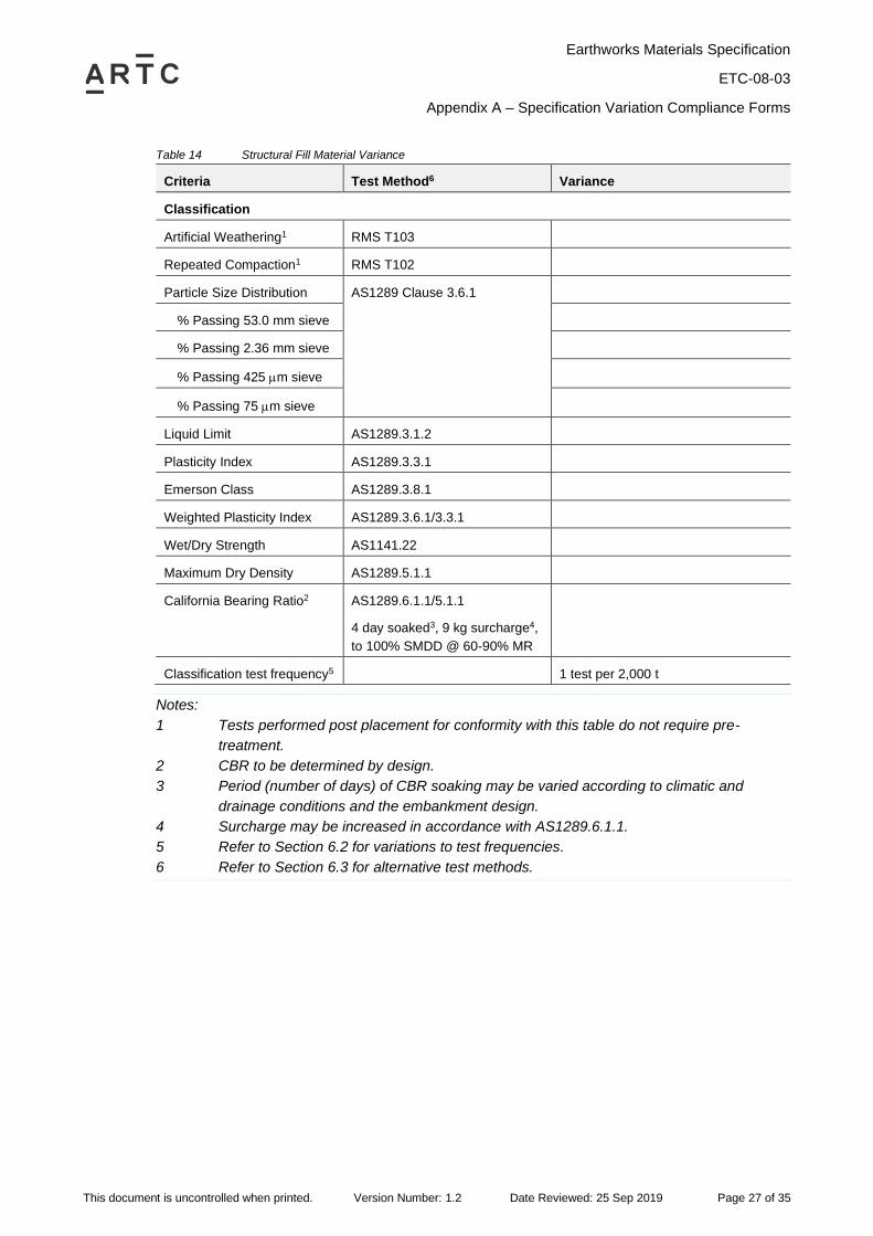
Table 14 Structural Fill Material Variance
Criteria Test Method6 Variance
Classification
Artificial Weathering1 RMS T103
Repeated Compaction1 RMS T102
Particle Size Distribution AS1289 Clause 3.6.1
% Passing 53.0 mm sieve
% Passing 2.36 mm sieve
% Passing 425 m sieve
% Passing 75 m sieve
Liquid Limit AS1289.3.1.2
Plasticity Index AS1289.3.3.1
Emerson Class AS1289.3.8.1
Weighted Plasticity Index AS1289.3.6.1/3.3.1
Wet/Dry Strength AS1141.22
Maximum Dry Density AS1289.5.1.1
California Bearing Ratio2 AS1289.6.1.1/5.1.1
4 day soaked3, 9 kg surcharge4,
to 100% SMDD @ 60-90% MR
Classification test frequency5 1 test per 2,000 t
Notes:
1 Tests performed post placement for conformity with this table do not require pre-
treatment.
2 CBR to be determined by design.
3 Period (number of days) of CBR soaking may be varied according to climatic and
drainage conditions and the embankment design.
4 Surcharge may be increased in accordance with AS1289.6.1.1.
5 Refer to Section 6.2 for variations to test frequencies.
6 Refer to Section 6.3 for alternative test methods.
Earthworks Materials Specification
ETC-08-03
Appendix A – Specification Variation Compliance Forms
This document is uncontrolled when printed. Version Number: 1.2 Date Reviewed: 25 Sep 2019 Page 28 of 35
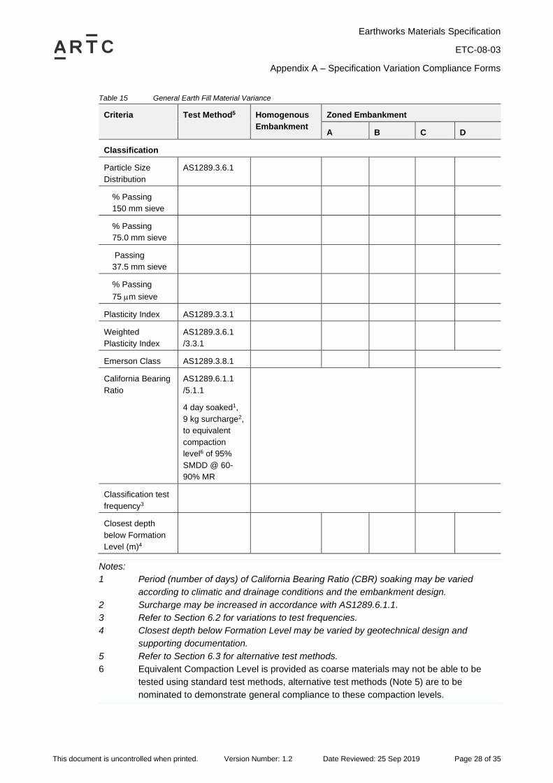
Table 15 General Earth Fill Material Variance
Criteria Test Method5 Homogenous
Embankment
Zoned Embankment
A B C D
Classification
Particle Size
Distribution
AS1289.3.6.1
% Passing
150 mm sieve
% Passing
75.0 mm sieve
Passing
37.5 mm sieve
% Passing
75 m sieve
Plasticity Index AS1289.3.3.1
Weighted
Plasticity Index
AS1289.3.6.1
/3.3.1
Emerson Class AS1289.3.8.1
California Bearing
Ratio
AS1289.6.1.1
/5.1.1
4 day soaked1,
9 kg surcharge2,
to equivalent
compaction
level6 of 95%
SMDD @ 60-
90% MR
Classification test
frequency3
Closest depth
below Formation
Level (m)4
Notes:
1 Period (number of days) of California Bearing Ratio (CBR) soaking may be varied
according to climatic and drainage conditions and the embankment design.
2 Surcharge may be increased in accordance with AS1289.6.1.1.
3 Refer to Section 6.2 for variations to test frequencies.
4 Closest depth below Formation Level may be varied by geotechnical design and
supporting documentation.
5 Refer to Section 6.3 for alternative test methods.
6 Equivalent Compaction Level is provided as coarse materials may not be able to be
tested using standard test methods, alternative test methods (Note 5) are to be
nominated to demonstrate general compliance to these compaction levels.
Earthworks Materials Specification
ETC-08-03
Appendix A – Specification Variation Compliance Forms
This document is uncontrolled when printed. Version Number: 1.2 Date Reviewed: 25 Sep 2019 Page 29 of 35
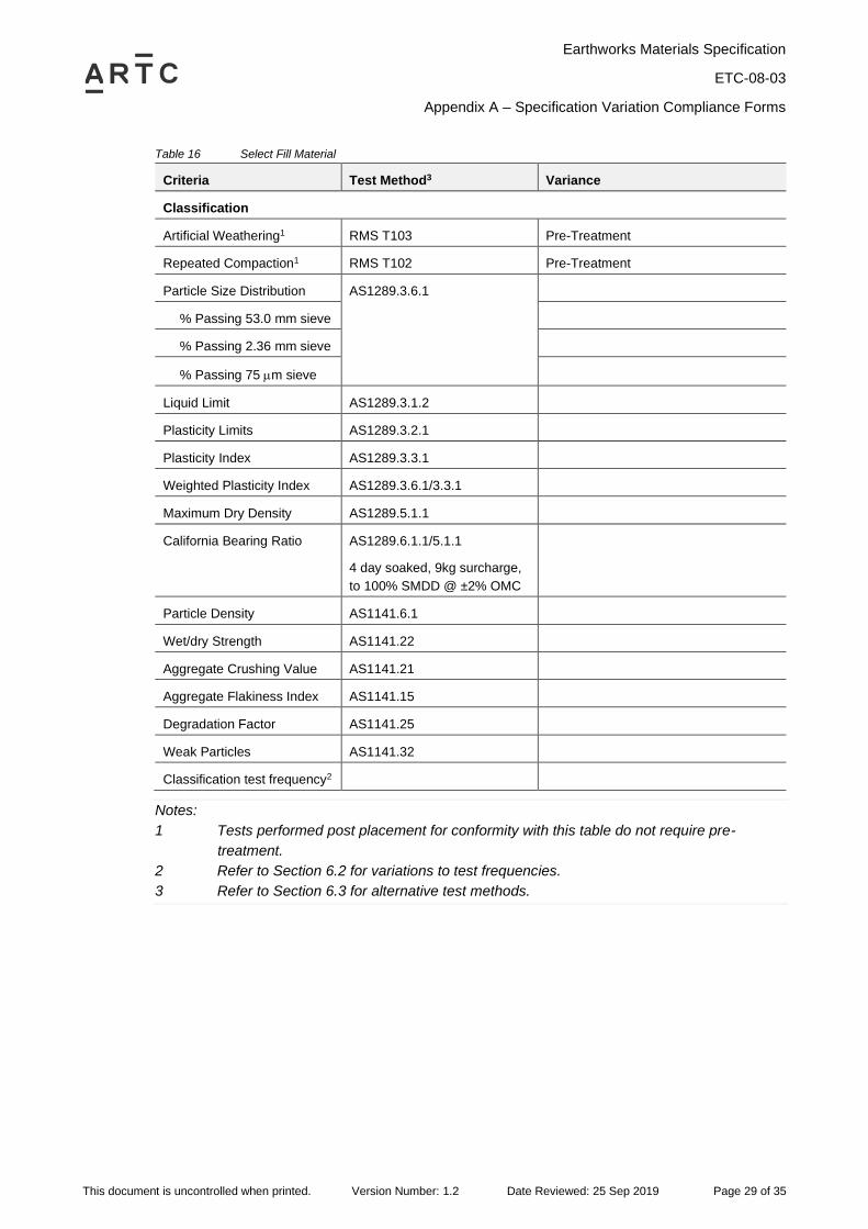
Table 16 Select Fill Material
Criteria Test Method3 Variance
Classification
Artificial Weathering1 RMS T103 Pre-Treatment
Repeated Compaction1 RMS T102 Pre-Treatment
Particle Size Distribution AS1289.3.6.1
% Passing 53.0 mm sieve
% Passing 2.36 mm sieve
% Passing 75 m sieve
Liquid Limit AS1289.3.1.2
Plasticity Limits AS1289.3.2.1
Plasticity Index AS1289.3.3.1
Weighted Plasticity Index AS1289.3.6.1/3.3.1
Maximum Dry Density AS1289.5.1.1
California Bearing Ratio AS1289.6.1.1/5.1.1
4 day soaked, 9kg surcharge,
to 100% SMDD @ ±2% OMC
Particle Density AS1141.6.1
Wet/dry Strength AS1141.22
Aggregate Crushing Value AS1141.21
Aggregate Flakiness Index AS1141.15
Degradation Factor AS1141.25
Weak Particles AS1141.32
Classification test frequency2
Notes:
1 Tests performed post placement for conformity with this table do not require pre-
treatment.
2 Refer to Section 6.2 for variations to test frequencies.
3 Refer to Section 6.3 for alternative test methods.
Earthworks Materials Specification
ETC-08-03
Appendix A – Specification Variation Compliance Forms
This document is uncontrolled when printed. Version Number: 1.2 Date Reviewed: 25 Sep 2019 Page 30 of 35
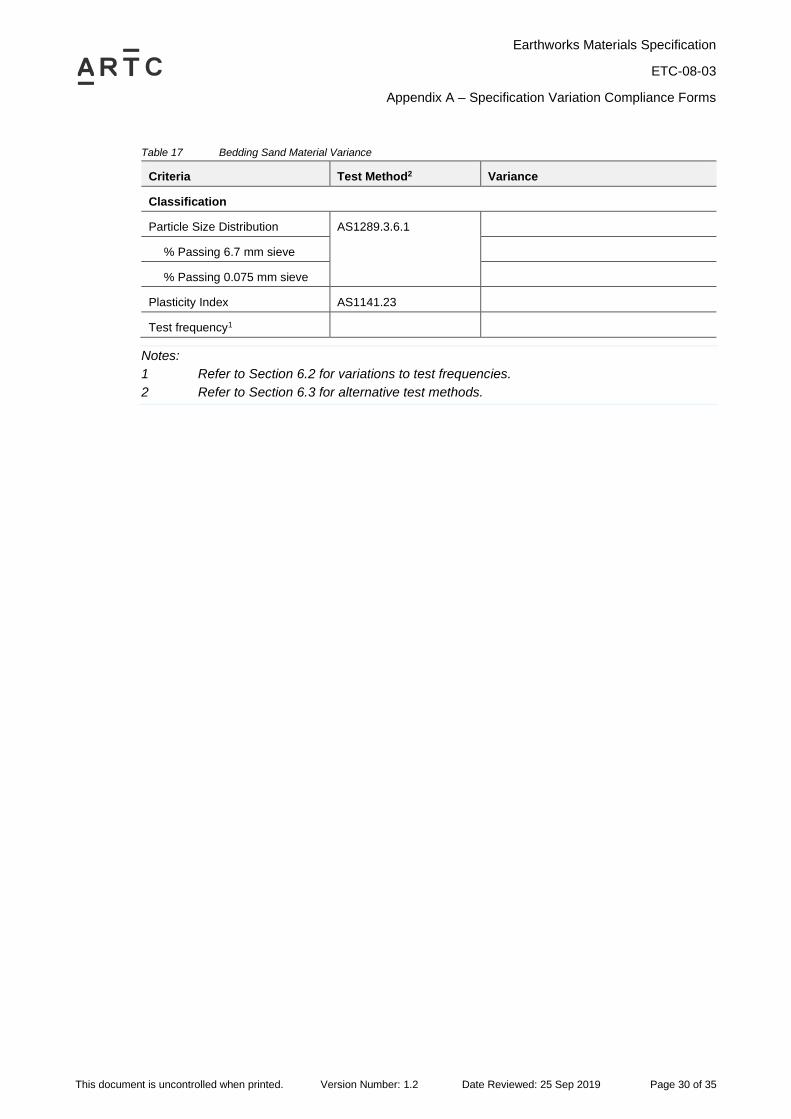
Table 17 Bedding Sand Material Variance
Criteria Test Method2 Variance
Classification
Particle Size Distribution AS1289.3.6.1
% Passing 6.7 mm sieve
% Passing 0.075 mm sieve
Plasticity Index AS1141.23
Test frequency1
Notes:
1 Refer to Section 6.2 for variations to test frequencies.
2 Refer to Section 6.3 for alternative test methods.
Earthworks Materials Specification
ETC-08-03
Appendix A – Specification Variation Compliance Forms
This document is uncontrolled when printed. Version Number: 1.2 Date Reviewed: 25 Sep 2019 Page 31 of 35
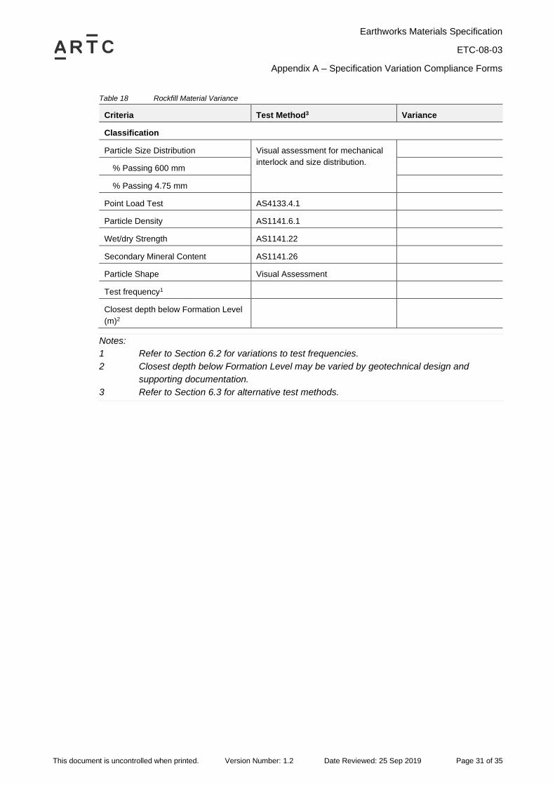
Table 18 Rockfill Material Variance
Criteria Test Method3 Variance
Classification
Particle Size Distribution Visual assessment for mechanical
interlock and size distribution.
% Passing 600 mm
% Passing 4.75 mm
Point Load Test AS4133.4.1
Particle Density AS1141.6.1
Wet/dry Strength AS1141.22
Secondary Mineral Content AS1141.26
Particle Shape Visual Assessment
Test frequency1
Closest depth below Formation Level
(m)2
Notes:
1 Refer to Section 6.2 for variations to test frequencies.
2 Closest depth below Formation Level may be varied by geotechnical design and
supporting documentation.
3 Refer to Section 6.3 for alternative test methods.
Earthworks Materials Specification
ETC-08-03
Appendix A – Specification Variation Compliance Forms
This document is uncontrolled when printed. Version Number: 1.2 Date Reviewed: 25 Sep 2019 Page 32 of 35
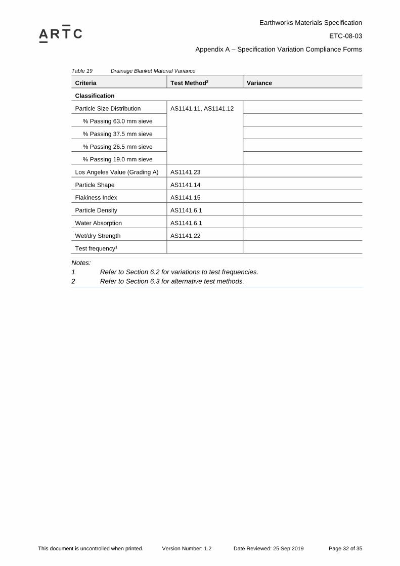
Table 19 Drainage Blanket Material Variance
Criteria Test Method2 Variance
Classification
Particle Size Distribution AS1141.11, AS1141.12
% Passing 63.0 mm sieve
% Passing 37.5 mm sieve
% Passing 26.5 mm sieve
% Passing 19.0 mm sieve
Los Angeles Value (Grading A) AS1141.23
Particle Shape AS1141.14
Flakiness Index AS1141.15
Particle Density AS1141.6.1
Water Absorption AS1141.6.1
Wet/dry Strength AS1141.22
Test frequency1
Notes:
1 Refer to Section 6.2 for variations to test frequencies.
2 Refer to Section 6.3 for alternative test methods.
Earthworks Materials Specification
ETC-08-03
Appendix A – Specification Variation Compliance Forms
This document is uncontrolled when printed. Version Number: 1.2 Date Reviewed: 25 Sep 2019 Page 33 of 35
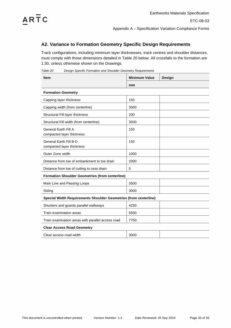
A2. Variance to Formation Geometry Specific Design Requirements
Track configurations, including minimum layer thicknesses, track centres and shoulder distances,
must comply with those dimensions detailed in Table 20 below. All crossfalls to the formation are
1:30, unless otherwise shown on the Drawings.
Table 20 Design Specific Formation and Shoulder Geometry Requirements
Item Minimum Value Design
mm
Formation Geometry
Capping layer thickness 150
Capping width (from centerline) 3500
Structural Fill layer thickness 200
Structural Fill width (from centerline) 3500
General Earth Fill A
compacted layer thickness
150
General Earth Fill B-D
compacted layer thickness
150
Outer Zone width 1000
Distance from toe of embankment to toe drain 2000
Distance from toe of cutting to cess drain 0
Formation Shoulder Geometries (from centerline)
Main Line and Passing Loops 3500
Siding 3000
Special Width Requirements Shoulder Geometries (from centerline)
Shunters and guards parallel walkways 4250
Train examination areas 5500
Train examination areas with parallel access road 7750
Clear Access Road Geometry
Clear access road width 3000
Earthworks Materials Specification
ETC-08-03
Appendix A – Specification Variation Compliance Forms
This document is uncontrolled when printed. Version Number: 1.2 Date Reviewed: 25 Sep 2019 Page 34 of 35
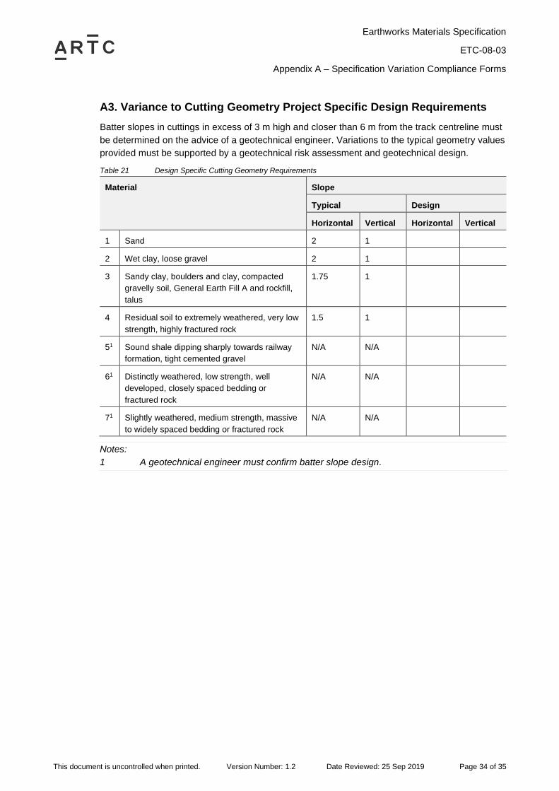
A3. Variance to Cutting Geometry Project Specific Design Requirements
Batter slopes in cuttings in excess of 3 m high and closer than 6 m from the track centreline must
be determined on the advice of a geotechnical engineer. Variations to the typical geometry values
provided must be supported by a geotechnical risk assessment and geotechnical design.
Table 21 Design Specific Cutting Geometry Requirements
Material Slope
Typical Design
Horizontal Vertical Horizontal Vertical
1 Sand 2 1
2 Wet clay, loose gravel 2 1
3 Sandy clay, boulders and clay, compacted
gravelly soil, General Earth Fill A and rockfill,
talus
1.75 1
4 Residual soil to extremely weathered, very low
strength, highly fractured rock
1.5 1
51 Sound shale dipping sharply towards railway
formation, tight cemented gravel
N/A N/A
61 Distinctly weathered, low strength, well
developed, closely spaced bedding or
fractured rock
N/A N/A
71 Slightly weathered, medium strength, massive
to widely spaced bedding or fractured rock
N/A N/A
Notes:
1 A geotechnical engineer must confirm batter slope design.
Earthworks Materials Specification
ETC-08-03
Appendix B – Changes to ARTC Standards Relating to this Specification
This document is uncontrolled when printed. Version Number: 1.2 Date Reviewed: 25 Sep 2019 Page 35 of 35
Appendix B – Changes to ARTC Standards Relating to this Specification