Embed Size (px)
Citation preview
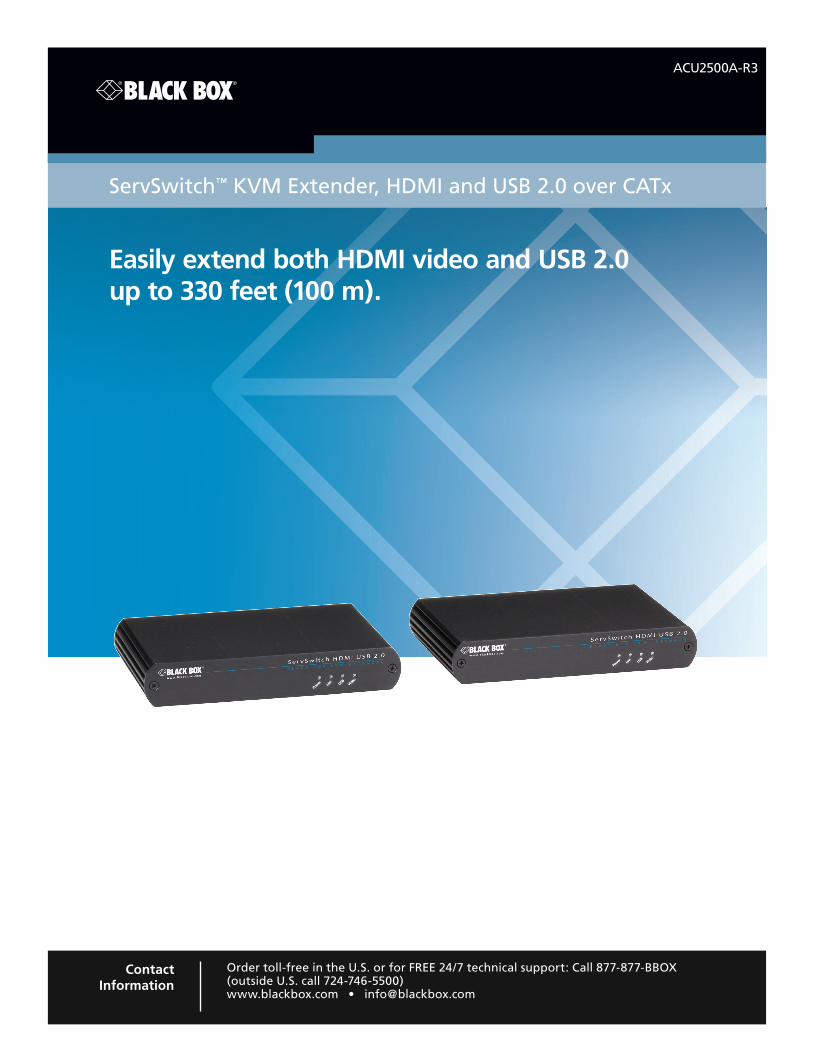
ACU2500A-R3
Easily extend both HDMI video and USB 2.0 up to 330 feet (100 m).
ServSwitch™ KVM Extender, HDMI and USB 2.0 over CATx
Order toll-free in the U.S. or for FREE 24/7 technical support: Call 877-877-BBOX (outside U.S. call 724-746-5500)www.blackbox.com • [email protected]
Contact Information
ACU2500A-R3

877-877-2269 | blackbox.com Page 2 ACU2500A-R3
Trademarks Used in this Manual/FCC and IC RFI Statement
Trademarks Used in this Manual
Black Box and the Double Diamond logo are registered trademarks, and ServSwitch is a trademark, of BB Technologies, Inc.
Mac and OS X are registered trademarks of Apple Computer, Inc.
Intel is a registered trademark of Intel Corporation.
Windows is a registered trademark of Microsoft Corporation.
Linux is a registered trademark of Linus Torvalds.
Any other trademarks mentioned in this manual are acknowledged to be the property of their respective owners.
Federal Communications Commission and Industry Canada Radio Frequency Interference Statements
This equipment generates, uses, and can radiate radio-frequency energy, and if not installed and used properly, that is, in strict accordance with the manufacturer’s instructions, may cause inter ference to radio communication. It has been tested and found to comply with the limits for a Class A computing device in accordance with the specifications in Subpart B of Part 15 of FCC rules, which are designed to provide reasonable protection against such interference when the equipment is operated in a commercial environment. Operation of this equipment in a residential area is likely to cause interference, in which case the user at his own expense will be required to take whatever measures may be necessary to correct the interference.
Changes or modifications not expressly approved by the party responsible for compliance could void the user’s authority to operate the equipment.
This digital apparatus does not exceed the Class A limits for radio noise emis sion from digital apparatus set out in the Radio Interference Regulation of Industry Canada.
Le présent appareil numérique n’émet pas de bruits radioélectriques dépassant les limites applicables aux appareils numériques de la classe A prescrites dans le Règlement sur le brouillage radioélectrique publié par Industrie Canada.
Page 3ACU2500A-R3 877-877-2269 | blackbox.com
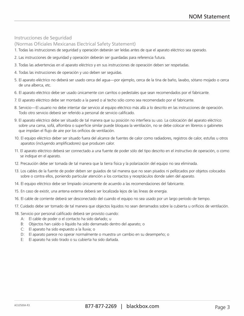
NOM Statement
Instrucciones de Seguridad(Normas Oficiales Mexicanas Electrical Safety Statement)1. Todas las instrucciones de seguridad y operación deberán ser leídas antes de que el aparato eléctrico sea operado.
2. Las instrucciones de seguridad y operación deberán ser guardadas para referencia futura.
3. Todas las advertencias en el aparato eléctrico y en sus instrucciones de operación deben ser respetadas.
4. Todas las instrucciones de operación y uso deben ser seguidas.
5. El aparato eléctrico no deberá ser usado cerca del agua—por ejemplo, cerca de la tina de baño, lavabo, sótano mojado o cerca de una alberca, etc.
6. El aparato eléctrico debe ser usado únicamente con carritos o pedestales que sean recomendados por el fabricante.
7. El aparato eléctrico debe ser montado a la pared o al techo sólo como sea recomendado por el fabricante.
8. Servicio—El usuario no debe intentar dar servicio al equipo eléctrico más allá a lo descrito en las instrucciones de operación. Todo otro servicio deberá ser referido a personal de servicio calificado.
9. El aparato eléctrico debe ser situado de tal manera que su posición no interfiera su uso. La colocación del aparato eléctrico sobre una cama, sofá, alfombra o superficie similar puede bloquea la ventilación, no se debe colocar en libreros o gabinetes que impidan el flujo de aire por los orificios de ventilación.
10. El equipo eléctrico deber ser situado fuera del alcance de fuentes de calor como radiadores, registros de calor, estufas u otros aparatos (incluyendo amplificadores) que producen calor.
11. El aparato eléctrico deberá ser connectado a una fuente de poder sólo del tipo descrito en el instructivo de operación, o como se indique en el aparato.
12. Precaución debe ser tomada de tal manera que la tierra fisica y la polarización del equipo no sea eliminada.
13. Los cables de la fuente de poder deben ser guiados de tal manera que no sean pisados ni pellizcados por objetos colocados sobre o contra ellos, poniendo particular atención a los contactos y receptáculos donde salen del aparato.
14. El equipo eléctrico debe ser limpiado únicamente de acuerdo a las recomendaciones del fabricante.
15. En caso de existir, una antena externa deberá ser localizada lejos de las lineas de energia.
16. El cable de corriente deberá ser desconectado del cuando el equipo no sea usado por un largo periodo de tiempo.
17. Cuidado debe ser tomado de tal manera que objectos liquidos no sean derramados sobre la cubierta u orificios de ventilación.
18. Servicio por personal calificado deberá ser provisto cuando: A: El cable de poder o el contacto ha sido dañado; u B: Objectos han caído o líquido ha sido derramado dentro del aparato; o C: El aparato ha sido expuesto a la lluvia; o D: El aparato parece no operar normalmente o muestra un cambio en su desempeño; o E: El aparato ha sido tirado o su cubierta ha sido dañada.
877-877-2269 | blackbox.com Page 4 ACU2500A-R3
Table of Contents
Table of Contents
1. Specifications .......................................................................................................................................................................5
2. Overview ..........................................................................................................................................................................6 2.1 Introduction .................................................................................................................................................................6 2.2 About the ServSwitch KVM Extender, HDMI and USB 2.0 over CATx ..........................................................................6 2.3 What’s Included ...........................................................................................................................................................6 2.4 Requirements ...............................................................................................................................................................6 2.5 Compatibility and Recommended Setup ......................................................................................................................7 2.6 Hardware Description ...................................................................................................................................................8 2.6.1 Local Extender ...................................................................................................................................................8 2.6.2 Remote Extender .............................................................................................................................................10
3. Installation ........................................................................................................................................................................ 12 3.1 Installing the Local Extender Unit ............................................................................................................................... 12 3.2 Installing the Remote Extender Unit ........................................................................................................................... 12 3.3 Connecting the Local Extender to the Remote Extender ............................................................................................ 12 3.4 Connecting Power to the Local Extender and Remote Extender ................................................................................ 13 3.5 Checking the Installation ............................................................................................................................................ 13 3.6 Connecting a USB Device ........................................................................................................................................... 13
4. Troubleshooting .................................................................................................................................................................14 4.1 Problems/Causes/Solutions ........................................................................................................................................14 4.2 Contacting Black Box ................................................................................................................................................. 15 4.3 Shipping and Packaging ............................................................................................................................................. 15
A. Technical Glossary ..............................................................................................................................................................16
Page 5ACU2500A-R3 877-877-2269 | blackbox.com
Chapter 1: Specifications
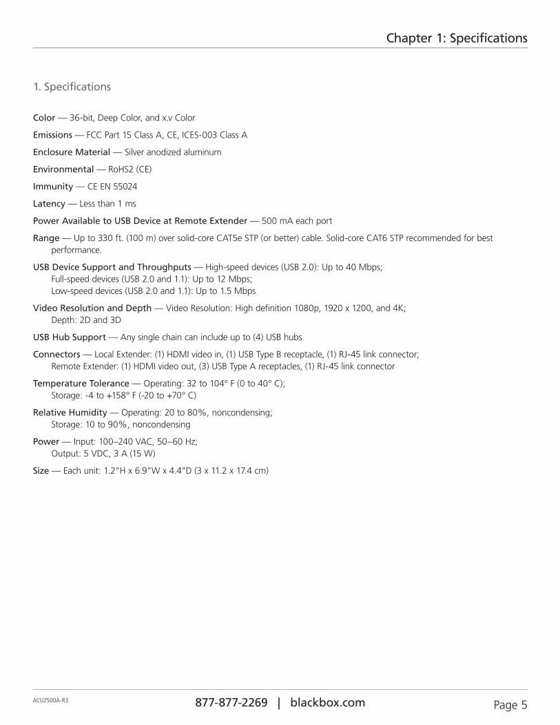
1. Specifications
Color — 36-bit, Deep Color, and x.v Color
Emissions — FCC Part 15 Class A, CE, ICES-003 Class A
Enclosure Material — Silver anodized aluminum
Environmental — RoHS2 (CE)
Immunity — CE EN 55024
Latency — Less than 1 ms
Power Available to USB Device at Remote Extender — 500 mA each port
Range — Up to 330 ft. (100 m) over solid-core CAT5e STP (or better) cable. Solid-core CAT6 STP recommended for best performance.
USB Device Support and Throughputs — High-speed devices (USB 2.0): Up to 40 Mbps; Full-speed devices (USB 2.0 and 1.1): Up to 12 Mbps; Low-speed devices (USB 2.0 and 1.1): Up to 1.5 Mbps
Video Resolution and Depth — Video Resolution: High definition 1080p, 1920 x 1200, and 4K; Depth: 2D and 3D
USB Hub Support — Any single chain can include up to (4) USB hubs
Connectors — Local Extender: (1) HDMI video in, (1) USB Type B receptacle, (1) RJ-45 link connector; Remote Extender: (1) HDMI video out, (3) USB Type A receptacles, (1) RJ-45 link connector
Temperature Tolerance — Operating: 32 to 104° F (0 to 40° C); Storage: -4 to +158° F (-20 to +70° C)
Relative Humidity — Operating: 20 to 80%, noncondensing; Storage: 10 to 90%, noncondensing
Power — Input: 100–240 VAC, 50–60 Hz; Output: 5 VDC, 3 A (15 W)
Size — Each unit: 1.2"H x 6.9"W x 4.4"D (3 x 11.2 x 17.4 cm)
877-877-2269 | blackbox.com Page 6 ACU2500A-R3
Chapter 2: Overview
2. Overview
2.1 IntroductionThe instructions in this guide assume a general knowledge of computer installation procedures, familiarity with cabling requirements, and some understanding of USB devices.
NOTES provide additional useful and important information.
CAUTIONS provide important information about an operational requirement.
2.2 About the ServSwitch KVM Extender, HDMI and USB 2.0 over CATxThe Extender incorporates a proprietary USB and HD video technology, which enables users to extend both HDMI video and USB 2.0 up to 330 feet (100 m). The following proprietary USB features are included:
• True plug-and-play.
• Supports all major operating systems: Windows®, Mac OS X®, and Linux®.
• Reliable operation with USB 2.0 and 1.1 devices and hubs.
2.3 What‘s Included• Local Extender
• Remote Extender
• (2) 5V DC power adapters
• USB Cable
• HDMI Cable
• Quick Start Guide and Warranty Information
NOTE: The product requires two power adapters, one for the local extender and one for the remote extender.
NOTE: This product supports CAT5e or better cabling (i.e., CAT6, CAT7, etc.). All references to “CAT5e” should be read as “CAT5e or better.”
2.4 RequirementsTo complete the installation, you will require the following items that are not included with the product:
• A computer that is USB compatible (with USB compliant operating system) and has an HDMI port;
• USB 1.1 or 2.0 compatible device(s);
• A minimum of CAT5e Shielded Twisted Pair (STP) cable with two CAT5e RJ-45 connectors (if using surface cabling), OR
• A minimum of CAT5e cabling with two information outlets and two CAT5e patch cords with CAT5e RJ-45 connectors (if using premise cabling).
NOTE: While CAT5e STP is the minimum category of twisted-pair cabling, for the best experience, and to minimize interference and crosstalk, CAT6 STP or better is strongly recommended. When using CAT5e cabling, the layout and quality of your cable runs and connections becomes extremely important. Please refer to the Cabling information in Section 2.5 for details.
Page 7ACU2500A-R3 877-877-2269 | blackbox.com
Chapter 2: Overview
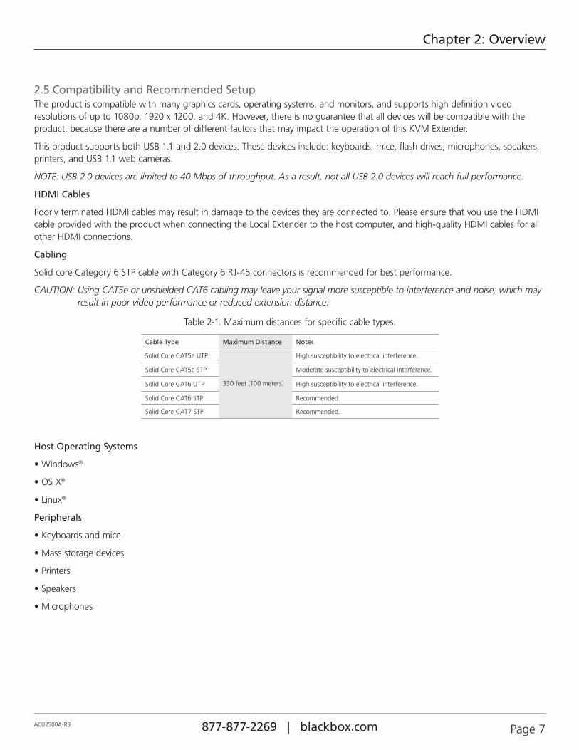
2.5 Compatibility and Recommended SetupThe product is compatible with many graphics cards, operating systems, and monitors, and supports high definition video resolutions of up to 1080p, 1920 x 1200, and 4K. However, there is no guarantee that all devices will be compatible with the product, because there are a number of different factors that may impact the operation of this KVM Extender.
This product supports both USB 1.1 and 2.0 devices. These devices include: keyboards, mice, flash drives, microphones, speakers, printers, and USB 1.1 web cameras.
NOTE: USB 2.0 devices are limited to 40 Mbps of throughput. As a result, not all USB 2.0 devices will reach full performance.
HDMI Cables
Poorly terminated HDMI cables may result in damage to the devices they are connected to. Please ensure that you use the HDMI cable provided with the product when connecting the Local Extender to the host computer, and high-quality HDMI cables for all other HDMI connections.
Cabling
Solid core Category 6 STP cable with Category 6 RJ-45 connectors is recommended for best performance.
CAUTION: Using CAT5e or unshielded CAT6 cabling may leave your signal more susceptible to interference and noise, which may result in poor video performance or reduced extension distance.
Table 2-1. Maximum distances for specific cable types.
Cable Type Maximum Distance Notes
Solid Core CAT5e UTP
330 feet (100 meters)
High susceptibility to electrical interference.
Solid Core CAT5e STP Moderate susceptibility to electrical interference.
Solid Core CAT6 UTP High susceptibility to electrical interference.
Solid Core CAT6 STP Recommended.
Solid Core CAT7 STP Recommended.
Host Operating Systems
• Windows®
• OS X®
• Linux®
Peripherals
• Keyboards and mice
• Mass storage devices
• Printers
• Speakers
• Microphones
877-877-2269 | blackbox.com Page 8 ACU2500A-R3
Chapter 2: Overview
HDMI Features
The KVM Extender is compatible with the following HDMI features:
• Full uncompressed high definition 1080p, 1920 x 1200, and 4K video resolution.
• Depth perception of 2D and 3D.
• Deep Color and x.v. Color
• Lip Sync Pass-through
• CEC Pass-through
• HDCP Pass-through
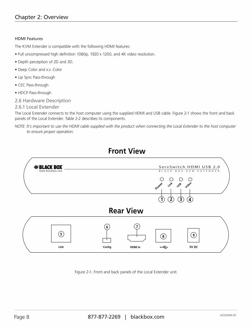
2.6 Hardware Description2.6.1 Local ExtenderThe Local Extender connects to the host computer using the supplied HDMI and USB cable. Figure 2-1 shows the front and back panels of the Local Extender. Table 2-2 describes its components.
NOTE: It’s important to use the HDMI cable supplied with the product when connecting the Local Extender to the host computer to ensure proper operation.
5V DC
1
Pow
er Link
USBVid
eo
2 3 4
9
6 7
5
Config HDMI InLink
Rear View
Front View
S e r v S w i t c h H D M I U S B 2 . 0B L A C K B O X K V M E X T E N D E R
8
Figure 2-1. Front and back panels of the Local Extender unit.
Page 9ACU2500A-R3 877-877-2269 | blackbox.com
Chapter 2: Overview
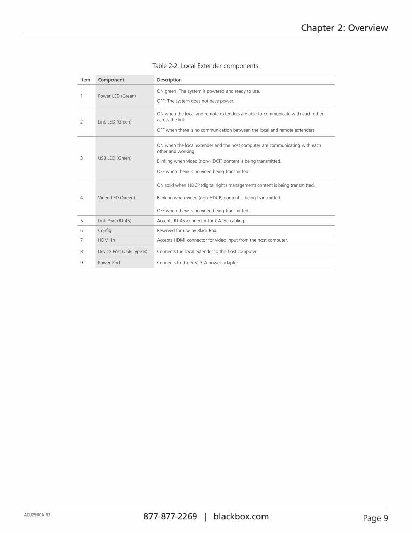
Table 2-2. Local Extender components.
Item Component Description
1 Power LED (Green)ON green: The system is powered and ready to use.
OFF: The system does not have power.
2 Link LED (Green)
ON when the local and remote extenders are able to communicate with each other across the link.
OFF when there is no communication between the local and remote extenders.
3 USB LED (Green)
ON when the local extender and the host computer are communicating with each other and working.
Blinking when video (non-HDCP) content is being transmitted.
OFF when there is no video being transmitted.
4 Video LED (Green)
ON solid when HDCP (digital rights management) content is being transmitted.
Blinking when video (non-HDCP) content is being transmitted.
OFF when there is no video being transmitted.
5 Link Port (RJ-45) Accepts RJ-45 connector for CAT5e cabling.
6 Config Reserved for use by Black Box.
7 HDMI In Accepts HDMI connector for video input from the host computer.
8 Device Port (USB Type B) Connects the local extender to the host computer.
9 Power Port Connects to the 5-V, 3-A power adapter.
877-877-2269 | blackbox.com Page 10 ACU2500A-R3
Chapter 2: Overview
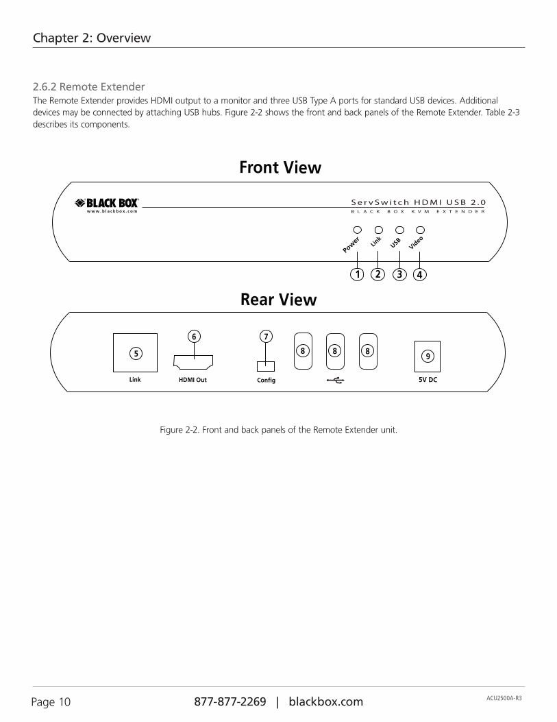
2.6.2 Remote ExtenderThe Remote Extender provides HDMI output to a monitor and three USB Type A ports for standard USB devices. Additional devices may be connected by attaching USB hubs. Figure 2-2 shows the front and back panels of the Remote Extender. Table 2-3 describes its components.
5V DC
1
Pow
er Link
USBVid
eo
2 3 4
8 8 8 9
7 6
5
ConfigHDMI OutLink
Rear View
Front View
S e r v S w i t c h H D M I U S B 2 . 0B L A C K B O X K V M E X T E N D E R
Figure 2-2. Front and back panels of the Remote Extender unit.
Page 11ACU2500A-R3 877-877-2269 | blackbox.com
Chapter 2: Overview
Table 2-3. Remote Extender components.
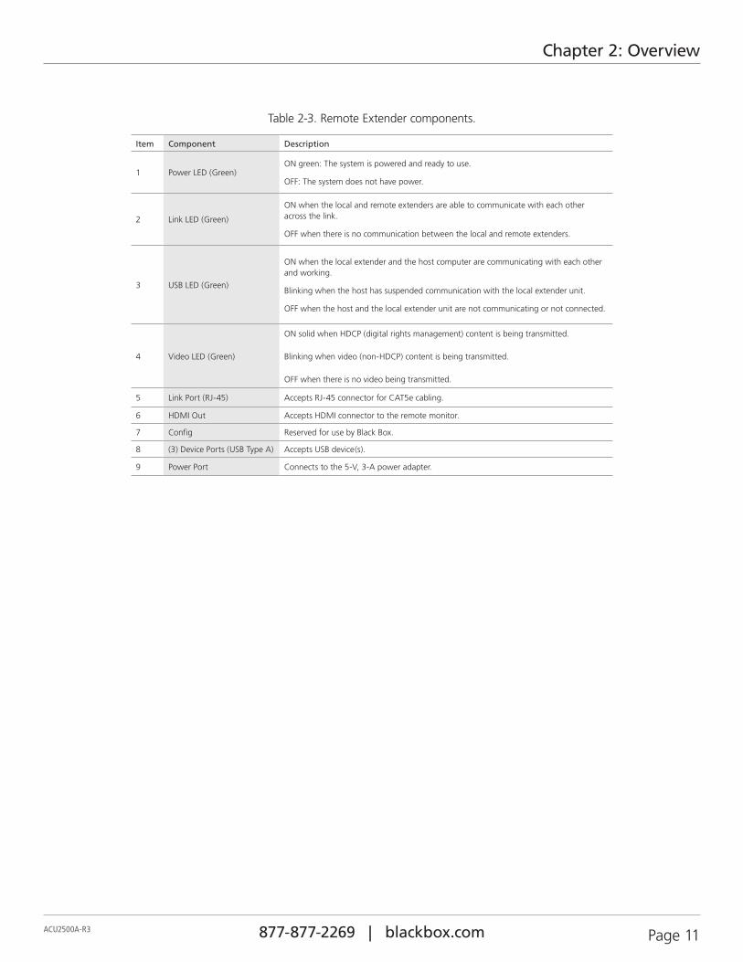
Item Component Description
1 Power LED (Green)ON green: The system is powered and ready to use.
OFF: The system does not have power.
2 Link LED (Green)
ON when the local and remote extenders are able to communicate with each other across the link.
OFF when there is no communication between the local and remote extenders.
3 USB LED (Green)
ON when the local extender and the host computer are communicating with each other and working.
Blinking when the host has suspended communication with the local extender unit.
OFF when the host and the local extender unit are not communicating or not connected.
4 Video LED (Green)
ON solid when HDCP (digital rights management) content is being transmitted.
Blinking when video (non-HDCP) content is being transmitted.
OFF when there is no video being transmitted.
5 Link Port (RJ-45) Accepts RJ-45 connector for CAT5e cabling.
6 HDMI Out Accepts HDMI connector to the remote monitor.
7 Config Reserved for use by Black Box.
8 (3) Device Ports (USB Type A) Accepts USB device(s).
9 Power Port Connects to the 5-V, 3-A power adapter.
877-877-2269 | blackbox.com Page 12 ACU2500A-R3
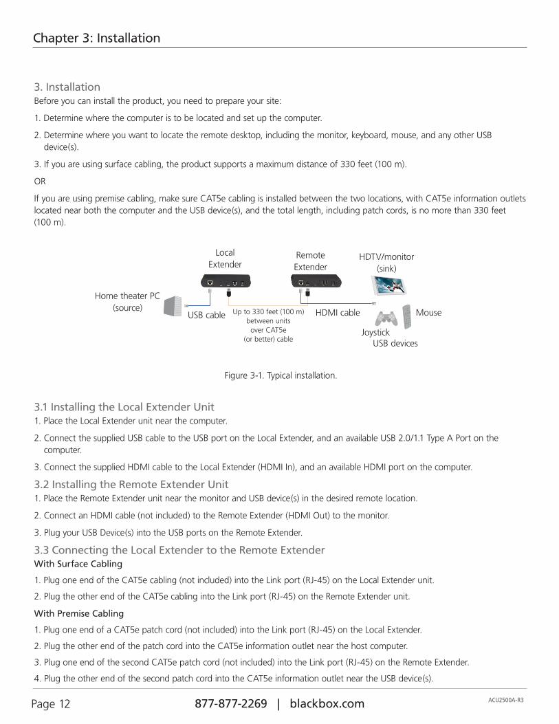
Chapter 3: Installation
3. InstallationBefore you can install the product, you need to prepare your site:
1. Determine where the computer is to be located and set up the computer.
2. Determine where you want to locate the remote desktop, including the monitor, keyboard, mouse, and any other USB device(s).
3. If you are using surface cabling, the product supports a maximum distance of 330 feet (100 m).
OR
If you are using premise cabling, make sure CAT5e cabling is installed between the two locations, with CAT5e information outlets located near both the computer and the USB device(s), and the total length, including patch cords, is no more than 330 feet (100 m).
Home theater PC (source) HDMI cable
Local Extender
Remote Extender
USB devices
Up to 330 feet (100 m) between units
over CAT5e (or better) cable
HDTV/monitor (sink)
USB cable
Joystick
Mouse
Figure 3-1. Typical installation.
3.1 Installing the Local Extender Unit1. Place the Local Extender unit near the computer.
2. Connect the supplied USB cable to the USB port on the Local Extender, and an available USB 2.0/1.1 Type A Port on the computer.
3. Connect the supplied HDMI cable to the Local Extender (HDMI In), and an available HDMI port on the computer.
3.2 Installing the Remote Extender Unit 1. Place the Remote Extender unit near the monitor and USB device(s) in the desired remote location.
2. Connect an HDMI cable (not included) to the Remote Extender (HDMI Out) to the monitor.
3. Plug your USB Device(s) into the USB ports on the Remote Extender.
3.3 Connecting the Local Extender to the Remote ExtenderWith Surface Cabling
1. Plug one end of the CAT5e cabling (not included) into the Link port (RJ-45) on the Local Extender unit.
2. Plug the other end of the CAT5e cabling into the Link port (RJ-45) on the Remote Extender unit.
With Premise Cabling
1. Plug one end of a CAT5e patch cord (not included) into the Link port (RJ-45) on the Local Extender.
2. Plug the other end of the patch cord into the CAT5e information outlet near the host computer.
3. Plug one end of the second CAT5e patch cord (not included) into the Link port (RJ-45) on the Remote Extender.
4. Plug the other end of the second patch cord into the CAT5e information outlet near the USB device(s).

Page 13ACU2500A-R3 877-877-2269 | blackbox.com
Chapter 3: Installation
3.4 Connecting Power to the Local and Remote Extenders1. Plug the supplied 5-V, 3-A power adapter into a suitable AC outlet near the Local Extender unit.
2. Connect the power adapter to the Local Extender unit.
3. Plug the supplied 5-V, 3-A power adapter into a suitable AC outlet near the Remote Extender unit.
4. Connect the power adapter to the Remote Extender unit.
CAUTION: Use only the power adapters supplied with the product. Use of substitute adapters may cause permanent damage to the system and will void the warranty.
3.5 Checking the Installation1. On the Local and Remote Extender units, check that the Power, Link, USB, and Video LEDs are on. If the Link LED is off, then
the cabling between the Local Extender and Remote Extender unit is not installed properly or is defective.
2. Check to see if the USB LED is on and the Video LED is blinking or on. If they are not, this indicates there is no USB data or video data. Check the HDMI and USB connections to the host computer, and the HDMI connection to the monitor. Check to see if any USB devices are connected to the Remote Extender unit.
3. If the product is not displaying video or your USB device fails to be detected by your operating system, consult Chapter 4, Troubleshooting.
3.6 Connecting a USB Device1. Install any software required to operate the USB device(s). Refer to the documentation provided for your USB device(s), as
required.
2. Connect the USB device to the device port on the Remote Extender unit.
3. Check that the USB device is detected and installed properly in the operating system.
877-877-2269 | blackbox.com Page 14 ACU2500A-R3
Chapter 4: Troubleshooting
4. Troubleshooting
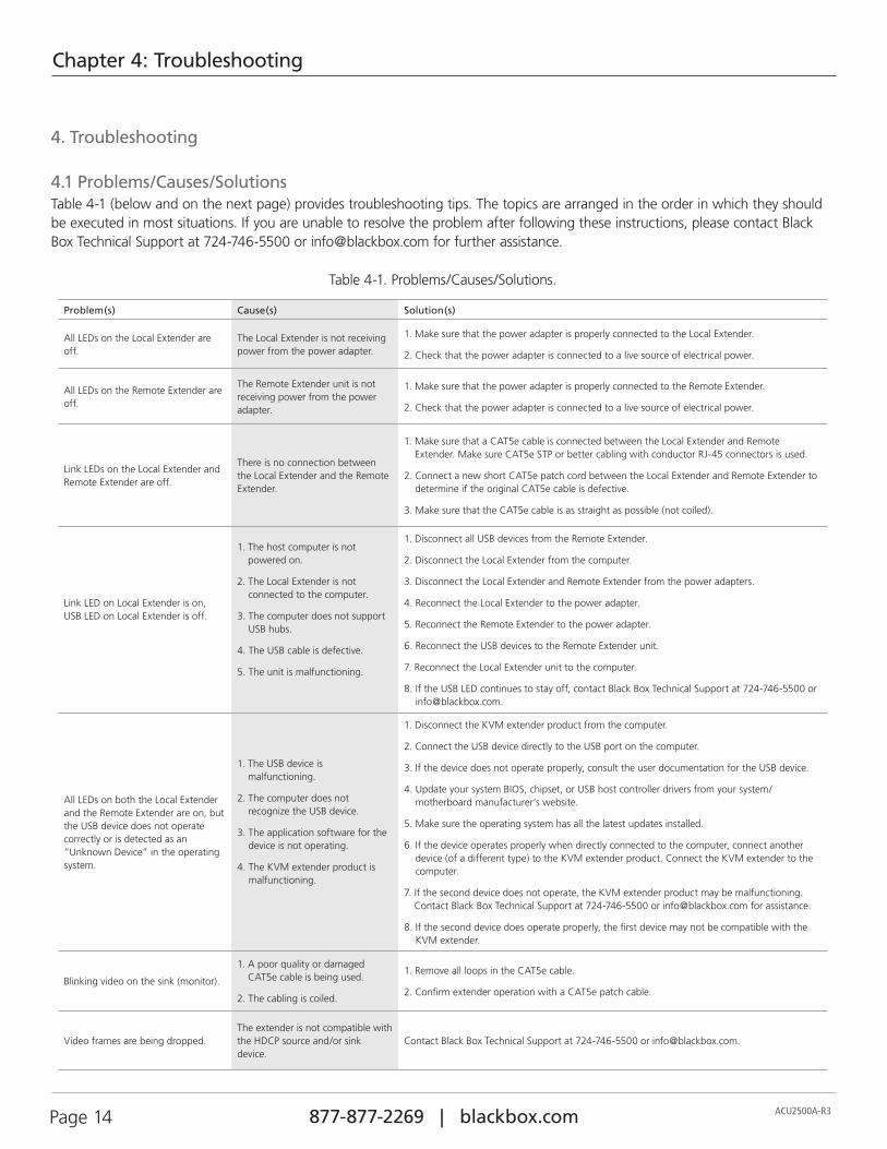
4.1 Problems/Causes/SolutionsTable 4-1 (below and on the next page) provides troubleshooting tips. The topics are arranged in the order in which they should be executed in most situations. If you are unable to resolve the problem after following these instructions, please contact Black Box Technical Support at 724-746-5500 or [email protected] for further assistance.
Table 4-1. Problems/Causes/Solutions.
Problem(s) Cause(s) Solution(s)
All LEDs on the Local Extender are off.
The Local Extender is not receiving power from the power adapter.
1. Make sure that the power adapter is properly connected to the Local Extender.
2. Check that the power adapter is connected to a live source of electrical power.
All LEDs on the Remote Extender are off.
The Remote Extender unit is not receiving power from the power adapter.
1. Make sure that the power adapter is properly connected to the Remote Extender.
2. Check that the power adapter is connected to a live source of electrical power.
Link LEDs on the Local Extender and Remote Extender are off.
There is no connection between the Local Extender and the Remote Extender.
1. Make sure that a CAT5e cable is connected between the Local Extender and Remote Extender. Make sure CAT5e STP or better cabling with conductor RJ-45 connectors is used.
2. Connect a new short CAT5e patch cord between the Local Extender and Remote Extender to determine if the original CAT5e cable is defective.
3. Make sure that the CAT5e cable is as straight as possible (not coiled).
Link LED on Local Extender is on, USB LED on Local Extender is off.
1. The host computer is not powered on.
2. The Local Extender is not connected to the computer.
3. The computer does not support USB hubs.
4. The USB cable is defective.
5. The unit is malfunctioning.
1. Disconnect all USB devices from the Remote Extender.
2. Disconnect the Local Extender from the computer.
3. Disconnect the Local Extender and Remote Extender from the power adapters.
4. Reconnect the Local Extender to the power adapter.
5. Reconnect the Remote Extender to the power adapter.
6. Reconnect the USB devices to the Remote Extender unit.
7. Reconnect the Local Extender unit to the computer.
8. If the USB LED continues to stay off, contact Black Box Technical Support at 724-746-5500 or [email protected].
All LEDs on both the Local Extender and the Remote Extender are on, but the USB device does not operate correctly or is detected as an “Unknown Device” in the operating system.
1. The USB device is malfunctioning.
2. The computer does not recognize the USB device.
3. The application software for the device is not operating.
4. The KVM extender product is malfunctioning.
1. Disconnect the KVM extender product from the computer.
2. Connect the USB device directly to the USB port on the computer.
3. If the device does not operate properly, consult the user documentation for the USB device.
4. Update your system BIOS, chipset, or USB host controller drivers from your system/ motherboard manufacturer‘s website.
5. Make sure the operating system has all the latest updates installed.
6. If the device operates properly when directly connected to the computer, connect another device (of a different type) to the KVM extender product. Connect the KVM extender to the computer.
7. If the second device does not operate, the KVM extender product may be malfunctioning. Contact Black Box Technical Support at 724-746-5500 or [email protected] for assistance.
8. If the second device does operate properly, the first device may not be compatible with the KVM extender.
Blinking video on the sink (monitor).
1. A poor quality or damaged CAT5e cable is being used.
2. The cabling is coiled.
1. Remove all loops in the CAT5e cable.
2. Confirm extender operation with a CAT5e patch cable.
Video frames are being dropped.The extender is not compatible with the HDCP source and/or sink device.
Contact Black Box Technical Support at 724-746-5500 or [email protected].
Page 15ACU2500A-R3 877-877-2269 | blackbox.com
Chapter 4: Troubleshooting
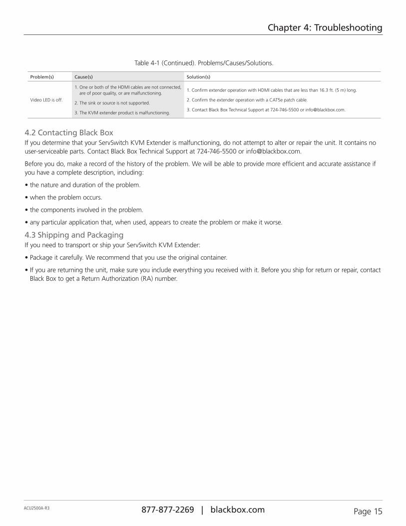
Table 4-1 (Continued). Problems/Causes/Solutions.
Problem(s) Cause(s) Solution(s)
Video LED is off.
1. One or both of the HDMI cables are not connected, are of poor quality, or are malfunctioning.
2. The sink or source is not supported.
3. The KVM extender product is malfunctioning.
1. Confirm extender operation with HDMI cables that are less than 16.3 ft. (5 m) long.
2. Confirm the extender operation with a CAT5e patch cable.
3. Contact Black Box Technical Support at 724-746-5500 or [email protected].
4.2 Contacting Black BoxIf you determine that your ServSwitch KVM Extender is malfunctioning, do not attempt to alter or repair the unit. It contains no user-serviceable parts. Contact Black Box Technical Support at 724-746-5500 or [email protected].
Before you do, make a record of the history of the problem. We will be able to provide more efficient and accurate assistance if you have a complete description, including:
• the nature and duration of the problem.
• when the problem occurs.
• the components involved in the problem.
• any particular application that, when used, appears to create the problem or make it worse.
4.3 Shipping and PackagingIf you need to transport or ship your ServSwitch KVM Extender:
• Package it carefully. We recommend that you use the original container.
• If you are returning the unit, make sure you include everything you received with it. Before you ship for return or repair, contact Black Box to get a Return Authorization (RA) number.
877-877-2269 | blackbox.com Page 16 ACU2500A-R3
Appendix A: Technical Glossary
Appendix A. Technical Glossary
Category 5 (CAT5) Network Cabling — Category 5 cable is commonly also referred to as CAT5. This cabling is available in either solid or stranded twisted pair copper wire variants and as UTP (Unshielded Twisted Pair) or STP (Shielded Twisted Pair). UTP cables are not surrounded by any shielding, making them more susceptible to electromagnetic interference (EMI). STP cables include shielding over each individual pair of copper wires that provides better protection against EMI. Category 5 has been superseded by CAT5e cabling, which includes improved data integrity to support high-speed communications.
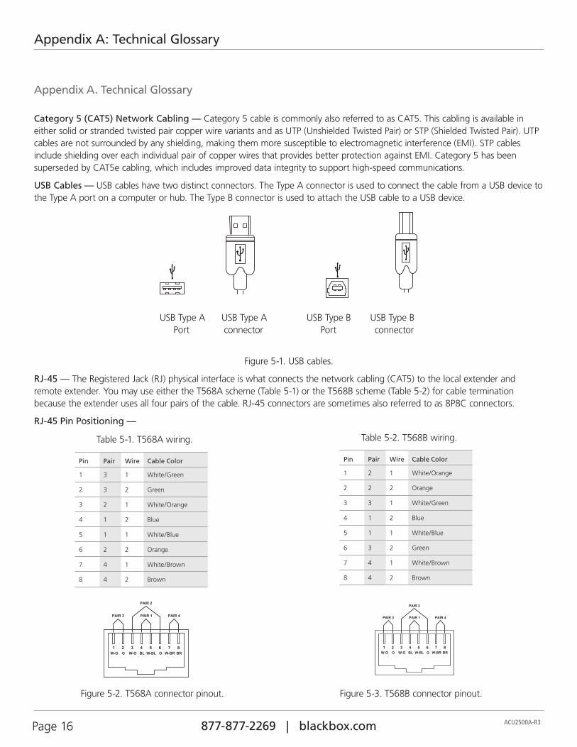
USB Cables — USB cables have two distinct connectors. The Type A connector is used to connect the cable from a USB device to the Type A port on a computer or hub. The Type B connector is used to attach the USB cable to a USB device.
USB Type A USB Type A USB Type B USB Type B Port connector Port connector
Figure 5-1. USB cables.
RJ-45 — The Registered Jack (RJ) physical interface is what connects the network cabling (CAT5) to the local extender and remote extender. You may use either the T568A scheme (Table 5-1) or the T568B scheme (Table 5-2) for cable termination because the extender uses all four pairs of the cable. RJ-45 connectors are sometimes also referred to as 8P8C connectors.
RJ-45 Pin Positioning —
Table 5-1. T568A wiring.
Pin Pair Wire Cable Color
1 3 1 White/Green
2 3 2 Green
3 2 1 White/Orange
4 1 2 Blue
5 1 1 White/Blue
6 2 2 Orange
7 4 1 White/Brown
8 4 2 Brown
Table 5-2. T568B wiring.
Pin Pair Wire Cable Color
1 2 1 White/Orange
2 2 2 Orange
3 3 1 White/Green
4 1 2 Blue
5 1 1 White/Blue
6 3 2 Green
7 4 1 White/Brown
8 4 2 Brown
Figure 5-2. T568A connector pinout. Figure 5-3. T568B connector pinout.

Page 17ACU2500A-R3 877-877-2269 | blackbox.com
NOTES
877-877-2269 | blackbox.com Page 18 ACU2500A-R3
NOTES

Page 19ACU2500A-R3 877-877-2269 | blackbox.com
NOTES

877-877-2269 | blackbox.com
Black Box Tech Support: FREE! Live. 24/7.
Tech support the way it should be.
Great tech support is just 60 seconds away at 877-877-2269 or blackbox.com.
ACU2500A-R3, version 3
About Black BoxBlack Box provides an extensive range of networking and infrastructure products. You’ll find everything from cabinets and racks and power and surge protection products to media converters and Ethernet switches all supported by free, live 24/7 Tech support available in 60 seconds or less.
© Copyright 2016. Black Box Corporation. All rights reserved.