Embed Size (px)
Citation preview
Instruction Manual
AMVnAutomated Microviscometer
Firmware Version: 1.7x

Instruction Manual
AMVnAutomated Microviscometer
Firmware Version: 1.7x
Anton Paar GmbH assumes no liability for technical or printing errors or omissions in this document.
Nor is any liability assumed for damages resulting from information contained in the document.
Anton Paar GmbH reserves the right to content changes. This also extends to changes to delivery volumes or any features of delivered parts.
All rights reserved (including translation). This document, or any part of it, may not be reproduced, changed, copied, or distributed by means of electronic systems in any form (print, photocopy, microfilm or any other process) without prior written permission by Anton Paar GmbH.
Trademarks, registered trademarks, trade names, etc. may be used in this manual without being marked as such. They are the property of their respective owner.
Published by Anton PaarPrinted: Anton Paar, AustriaCopyright © 2008 Anton Paar GmbH, Graz, Austria
Address: Anton Paar GmbHAnton-Paar-Str. 20A-8054 Graz / Austria – EuropeTel: +43 316 257-0Fax: +43 316 257-257
E-Mail: [email protected]: www.anton-paar.com
Date: July 2008
Document no.: B80IB01O.fm
Contents
1 About the Instruction Manual ......................................................................................................... 82 Safety Instructions........................................................................................................................... 9
2.1 General Safety Instructions ..................................................................................................... 92.1.1 Liability ..................................................................................................................... 92.1.2 Installation and Use.................................................................................................. 92.1.3 Maintenance and Service......................................................................................... 92.1.4 Disposal.................................................................................................................. 102.1.5 Returns................................................................................................................... 102.1.6 Precautions for Highly Inflammable Samples and Cleaning Agents ...................... 10
2.2 Warning Symbols on the AMVn Instrument............................................................................113 AMVn - An Overview...................................................................................................................... 124 Unpacking and Checking the Supplied Items ............................................................................. 13
4.1 Unpacking Supplied Items..................................................................................................... 134.2 Checking of Supplied Items................................................................................................... 13
4.2.1 Supplied Parts ....................................................................................................... 134.2.2 Accessories in the Measuring System Set ............................................................. 14
4.2.2.1 Available Measuring System Sets .......................................................... 144.2.2.2 Content of a Measuring System Set ....................................................... 15
4.2.3 Optional Accessories ............................................................................................. 165 Functional Components................................................................................................................ 17
5.1 Front of AMVn........................................................................................................................ 175.2 Rear Side of AMVn ............................................................................................................... 175.3 Measuring System ................................................................................................................ 185.4 Monitor and Function Keys.................................................................................................... 18
6 Putting AMVn into Operation........................................................................................................ 196.1 Activating AMVn .................................................................................................................... 196.2 Preparing the Measurement .................................................................................................. 20
6.2.1 Introducing the Ball to the Capillary ....................................................................... 206.2.2 Attaching the Filling Adapter .................................................................................. 206.2.3 Filling the Capillary ................................................................................................. 216.2.4 Attaching Temperature Tube .................................................................................. 216.2.5 Mounting the Capillary into the AMVn Instrument .................................................. 226.2.6 Attaching Protective Cap........................................................................................ 22
7 Measurement................................................................................................................................. 237.1 Setting up AMVn.................................................................................................................... 237.2 Starting the Measurement...................................................................................................... 24
7.2.1 Thermostatting the Capillary Block......................................................................... 247.2.2 Sample Thermostatting .......................................................................................... 247.2.3 Measuring the Sample ........................................................................................... 25
B80IB01 5
7.3 Displaying the Measured Values ........................................................................................... 257.4 Printing the Measured Values................................................................................................ 267.5 Cleaning the Measuring System............................................................................................ 27
8 AMVn Firmware Update................................................................................................................. 288.1 Menu – "SETUP Instrument" ................................................................................................. 28
8.1.1 Date and Time........................................................................................................ 288.1.2 Temperature Equilibration ...................................................................................... 29
8.1.2.1 Temperature Equilibration in "constant mode" ........................................ 298.1.2.2 Temperature Equilibration in "auto mode"............................................... 29
8.1.3 Default Settings ...................................................................................................... 308.1.4 Printer Configuration .............................................................................................. 308.1.5 Software Update..................................................................................................... 318.1.6 Zero Point Adjustment............................................................................................ 31
8.2 Menu – "SETUP Measurement" ............................................................................................ 328.2.1 Method ................................................................................................................... 328.2.2 Measuring System.................................................................................................. 34
8.3 Menu – "Print Configuration" ................................................................................................. 359 Calibration of Measuring Systems............................................................................................... 36
9.1 Calibrated and Uncalibrated Capillaries ................................................................................ 369.2 Menu Calibration.................................................................................................................... 369.3 Calibrating a New Measuring System.................................................................................... 37
10 Maintenance ................................................................................................................................... 3810.1 Cleaning the Measuring System............................................................................................ 3810.2 Cleaning the Filling Adapter................................................................................................... 3810.3 Cleaning AMVn...................................................................................................................... 3910.4 Wetted Parts of AMVn ........................................................................................................... 3910.5 Replacing O-rings in the Filling Adapter ................................................................................ 40
10.5.1 Filling Adapter Without Engraved Marking Ring .................................................... 4010.5.2 Filling Adapter With Engraved Marking Ring ......................................................... 4010.5.3 Exchanging the O-rings.......................................................................................... 40
11 Technical Data................................................................................................................................ 41Appendix A: Viscosity..................................................................................................................... 42
A.1 Viscosity Standard Fluids .................................................................................... 42A.2 Calibration Constant K1 ...................................................................................... 43A.3 Determining the Viscosity.................................................................................... 43
Appendix B: Extension of the Measuring Range.......................................................................... 44B.1 Quadrupling the Maximum Measuring Range..................................................... 44B.2 Doubling the Maximum Measuring Range .......................................................... 45
Appendix C: Menu Tree – Firmware Structure.............................................................................. 46
6 B80IB01

B80IB01 7
1 About the Instruction Manual
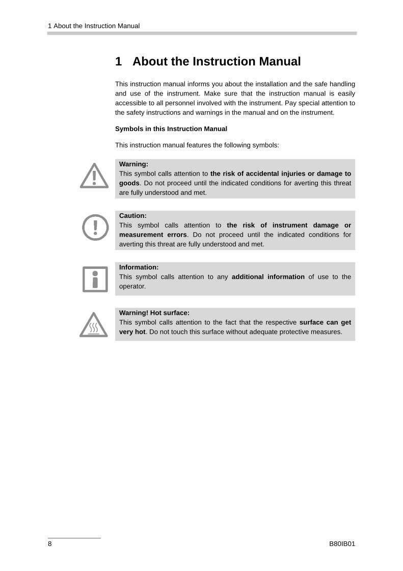
1 About the Instruction ManualThis instruction manual informs you about the installation and the safe handlingand use of the instrument. Make sure that the instruction manual is easilyaccessible to all personnel involved with the instrument. Pay special attention tothe safety instructions and warnings in the manual and on the instrument.
Symbols in this Instruction Manual
This instruction manual features the following symbols:
Warning:This symbol calls attention to the risk of accidental injuries or damage togoods. Do not proceed until the indicated conditions for averting this threatare fully understood and met.
Caution:This symbol calls attention to the risk of instrument damage ormeasurement errors. Do not proceed until the indicated conditions foraverting this threat are fully understood and met.
Information:This symbol calls attention to any additional information of use to theoperator.
Warning! Hot surface:This symbol calls attention to the fact that the respective surface can getvery hot. Do not touch this surface without adequate protective measures.
8 B80IB01
2 Safety Instructions
2 Safety Instructions• Read the instruction manual at hand before using AMVn.
• Follow all hints and instructions contained in this instruction manual toensure the correct use and safe functioning of AMVn.
2.1 General Safety Instructions
2.1.1 Liability
• The instruction manual at hand does not claim to address all safety issuesassociated with the use of the instrument and samples. It is yourresponsibility to establish health and safety practices and determine theapplicability of regulatory limitations.
• Anton Paar GmbH only warrants the proper functioning of AMVn if noadjustments have been made to the mechanics, electronics and firmware.
• Only use AMVn for the purpose described in this instruction manual. AntonPaar GmbH is not liable for damages caused by incorrect use of AMVn.
2.1.2 Installation and Use
• AMVn is not an explosion-proof instrument and therefore must not beoperated in areas with risk of explosion.
• The installation procedure should only be carried out by authorizedpersonnel who are familiar with the installation instructions.
• Do not use any accessories or wearing parts other than those supplied orapproved by Anton Paar GmbH.
• Make sure all operators are trained to use the instrument safely and correctlybefore starting any applicable operations.
• In case of damage or malfunction, do not continue operating AMVn. Do notoperate the instrument under conditions which could result in damage togoods and/or injuries and loss of life.
• Check AMVn for chemical resistance to the samples and cleaning agents.
2.1.3 Maintenance and Service
• The results delivered by AMVn not only depend on the correct function of theinstrument, but also on various other factors. We therefore recommend tohave the results checked (e.g. plausibility tested) by skilled personnel beforeconsequential actions are taken based on the results.
B80IB01 9
2 Safety Instructions
• Service and repair procedures may only be carried out by authorizedpersonnel or by Anton Paar GmbH.
2.1.4 Disposal
• Concerning the disposal of AMVn, observe the legal requirements in yourcountry.
2.1.5 Returns
• For repairs send the cleaned AMVn instrument to your Anton Paarrepresentative. Only return the instrument together with the filled out"Maintenance/Error Report" and the "Standard Maintenance Contract". Findthe applicable forms on the Anton Paar homepage (www.anton-paar.com).
2.1.6 Precautions for Highly Inflammable Samples and Cleaning Agents
• Observe and adhere to your national safety regulations for handling themeasured samples (e.g. use of safety goggles, gloves, respiratory protectionetc.).
• Only store the minimum required amount of sample, cleaning agents andother inflammable materials near the AMVn.
• Do not spill sample/cleaning agents or leave their containers uncovered.Immediately remove spilled sample/cleaning agents.
• Make sure that the setup location is sufficiently ventilated. The environmentof AMVn must be kept free of inflammable gases and vapors.
• Connect AMVn to the mains via a safety switch located at a safe distancefrom the instrument. In an emergency, turn off the power using this switchinstead of the power switch on AMVn.
• Supply a fire extinction unit.
• Ensure the sufficient supervision of AMVn during operation.
10 B80IB01
2 Safety Instructions
2.2 Warning Symbols on the AMVn Instrument
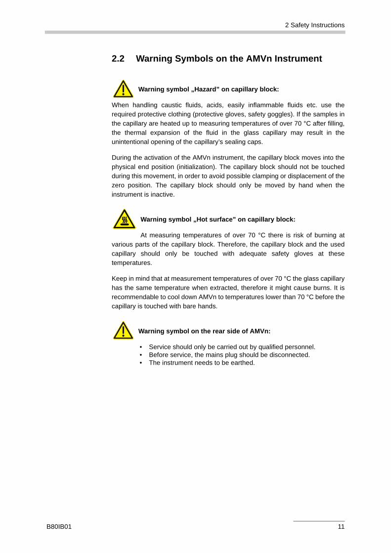
Warning symbol „Hazard” on capillary block:
When handling caustic fluids, acids, easily inflammable fluids etc. use therequired protective clothing (protective gloves, safety goggles). If the samples inthe capillary are heated up to measuring temperatures of over 70 °C after filling,the thermal expansion of the fluid in the glass capillary may result in theunintentional opening of the capillary’s sealing caps.
During the activation of the AMVn instrument, the capillary block moves into thephysical end position (initialization). The capillary block should not be touchedduring this movement, in order to avoid possible clamping or displacement of thezero position. The capillary block should only be moved by hand when theinstrument is inactive.
Warning symbol „Hot surface” on capillary block:
At measuring temperatures of over 70 °C there is risk of burning atvarious parts of the capillary block. Therefore, the capillary block and the usedcapillary should only be touched with adequate safety gloves at thesetemperatures.
Keep in mind that at measurement temperatures of over 70 °C the glass capillaryhas the same temperature when extracted, therefore it might cause burns. It isrecommendable to cool down AMVn to temperatures lower than 70 °C before thecapillary is touched with bare hands.
Warning symbol on the rear side of AMVn:
• Service should only be carried out by qualified personnel.• Before service, the mains plug should be disconnected.• The instrument needs to be earthed.
B80IB01 11
3 AMVn - An Overview
3 AMVn - An OverviewAnton Paar GmbH thanks you for buying AMVn, the global vanguard measuringinstrument for the automatic, high-precision viscosity determination of low viscoussubstances. It provides you with measurement solutions of utmost precision in avery broad viscosity and temperature measurement range.
The measurement principle of AMVn is the rolling ball/falling ball principle inaccordance with DIN 53015 and ISO 12058. It consists of the measurement of aball’s rolling time in a diagonally mounted glass capillary filled with sample. Theshear rate is influenced by changing the inclination angle of the capillary.In this way, investigations are implemented on whether the measured samplesare Newtonian or non-Newtonian (pseudoplastic or dilatant) fluids.
A built-in Pt100 temperature sensor is used for precise temperaturemeasurements and temperature regulation.
Choose various measurement methods and systems that accord with yourmeasurement applications.
You can print and display measurement results with sample names andmeasurement system data. Only the most recent measurement result is saved inthe AMVn instrument.
In the case of multiple measurement results, it is recommendable to immediatelyprint or note the data. With the optional VisioLab Windows Software, all results can be saved andevaluated in Excel.
The optionally delivered, fully automatic sample changers of Anton Paar GmbHautomatically fill the AMVn capillaries with samples. Between measurements thecapillaries are automatically cleaned with two cleaning agents, and consecutivelydried in air.
Our trained Anton Paar GmbH personnel always welcome your requests and willgladly provide you with additional offers.
12 B80IB01
4 Unpacking and Checking the Supplied Items
4 Unpacking and Checking the Supplied Items
4.1 Unpacking Supplied Items
AMVn was tested and packed carefully before shipment. However, damage mayoccur during transport.
• Keep the packaging material (box, foam piece, transport protection) forpossible returns and further questions from the transport- and insurancecompany.
• Compare the supplied parts to those noted in the table to check the deliveryfor completion.
• If a part is missing, contact your Anton Paar representative.
• If a part is damaged, contact the transport company and your Anton Paarrepresentative.
4.2 Checking of Supplied Items
The following tables list all supplied items contained in your order. Everyinstrument is delivered as a unit.
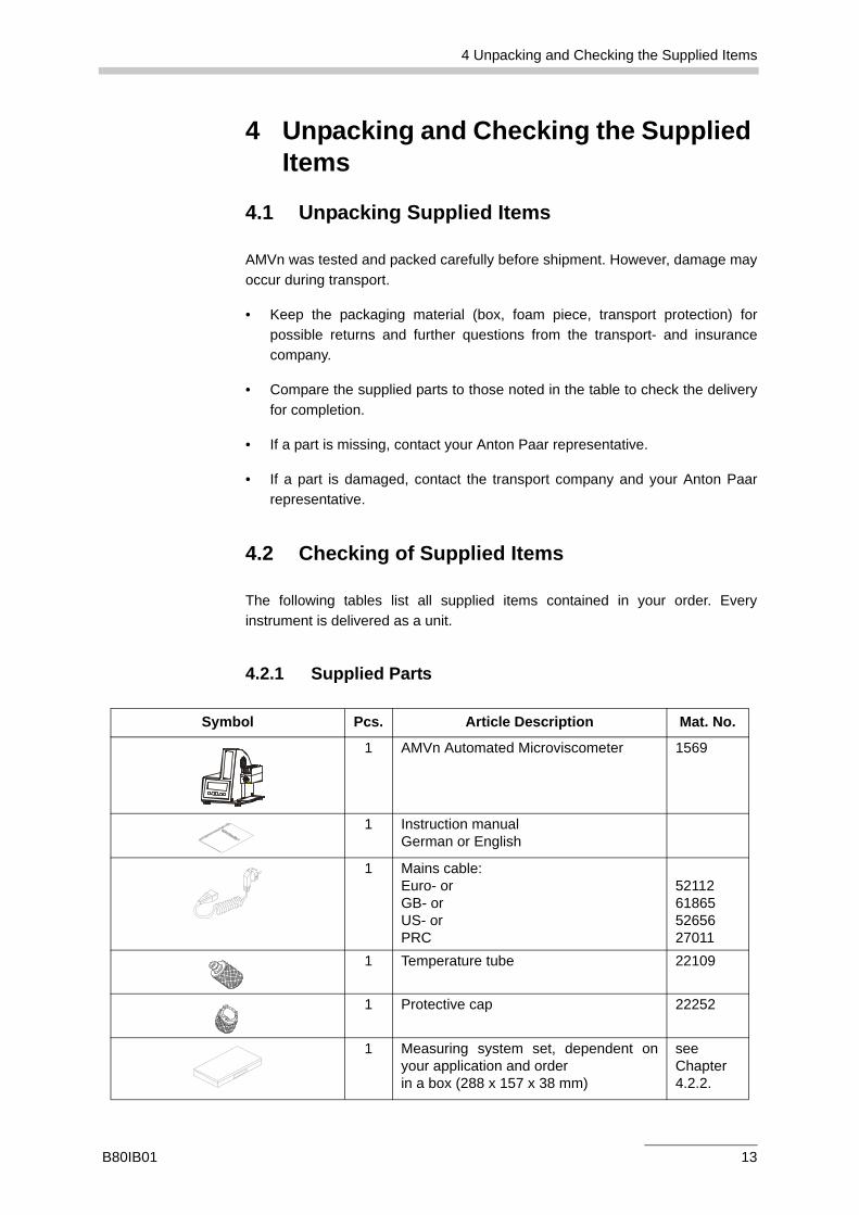
4.2.1 Supplied Parts
Symbol Pcs. Article Description Mat. No.
1 AMVn Automated Microviscometer 1569
1 Instruction manualGerman or English
1 Mains cable:Euro- orGB- or US- orPRC
52112618655265627011
1 Temperature tube 22109
1 Protective cap 22252
1 Measuring system set, dependent onyour application and orderin a box (288 x 157 x 38 mm)
seeChapter4.2.2.
B80IB01 13
4 Unpacking and Checking the Supplied Items
4.2.2 Accessories in the Measuring System Set
A measuring system set is delivered in a box, including all necessary parts fora measurement with AMVn. Every measuring system set includes the measuringsystem that accords with your order.
The measuring system is a combination of a capillary and a diametricallymatching ball.
The identification is determined by the internal diameter of the capillary: e.g. the measuring system (set) 1.6 which is comprised of: a capillary (diameter 1.6 mm) and balls (diameter 1.5 mm).
Find a listing of all measuring system sets and all parts contained in the box in thetables below. You can order all registered parts either in a set (Chapter 4.2.2.1)or separately, in reference to the material number listed on the right (Chapter4.2.2.2).
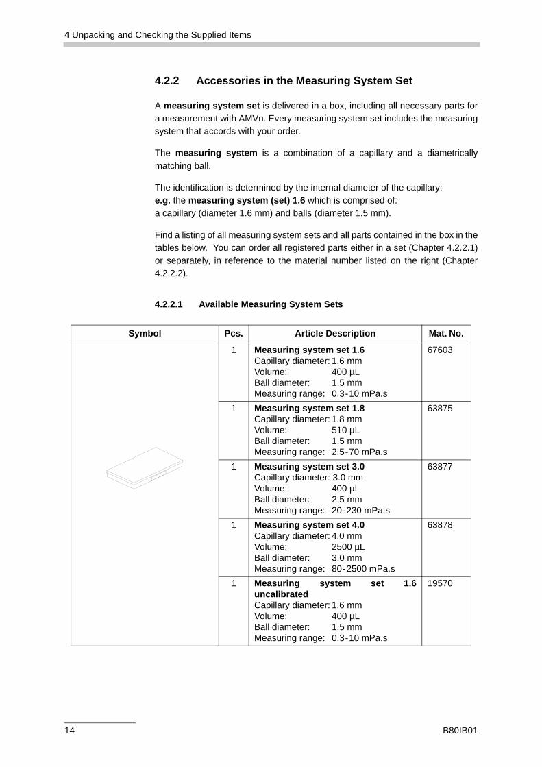
4.2.2.1 Available Measuring System Sets
Symbol Pcs. Article Description Mat. No.
1 Measuring system set 1.6Capillary diameter: 1.6 mmVolume: 400 µLBall diameter: 1.5 mmMeasuring range: 0.3-10 mPa.s
67603
1 Measuring system set 1.8Capillary diameter: 1.8 mmVolume: 510 µLBall diameter: 1.5 mmMeasuring range: 2.5-70 mPa.s
63875
1 Measuring system set 3.0Capillary diameter: 3.0 mmVolume: 400 µLBall diameter: 2.5 mmMeasuring range: 20-230 mPa.s
63877
1 Measuring system set 4.0Capillary diameter: 4.0 mmVolume: 2500 µLBall diameter: 3.0 mmMeasuring range: 80-2500 mPa.s
63878
1 Measuring system set 1.6uncalibratedCapillary diameter: 1.6 mmVolume: 400 µLBall diameter: 1.5 mmMeasuring range: 0.3-10 mPa.s
19570
14 B80IB01
4 Unpacking and Checking the Supplied Items
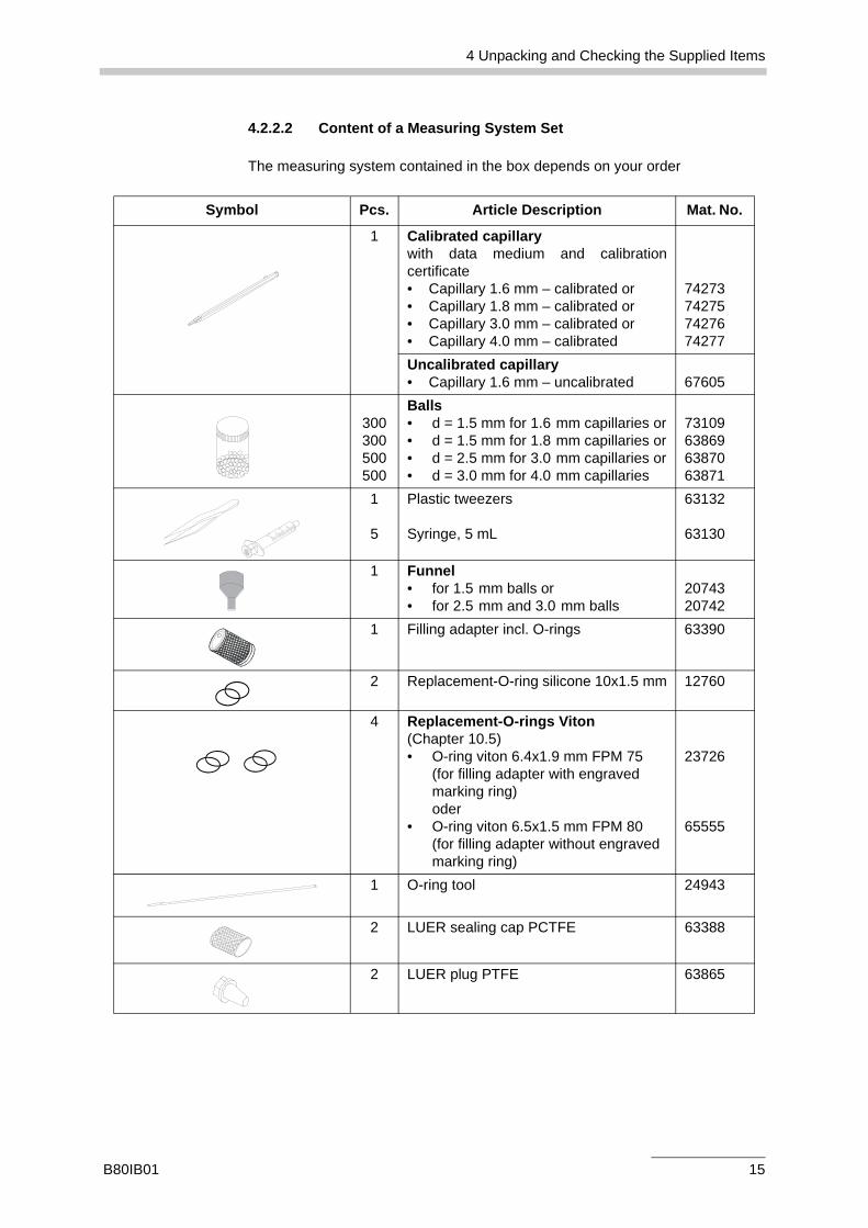
4.2.2.2 Content of a Measuring System Set
The measuring system contained in the box depends on your order
Symbol Pcs. Article Description Mat. No.
1 Calibrated capillarywith data medium and calibrationcertificate• Capillary 1.6 mm – calibrated or• Capillary 1.8 mm – calibrated or• Capillary 3.0 mm – calibrated or• Capillary 4.0 mm – calibrated
74273742757427674277
Uncalibrated capillary• Capillary 1.6 mm – uncalibrated 67605
300300500500
Balls • d = 1.5 mm for 1.6 mm capillaries or• d = 1.5 mm for 1.8 mm capillaries or• d = 2.5 mm for 3.0 mm capillaries or• d = 3.0 mm for 4.0 mm capillaries
73109638696387063871
1
5
Plastic tweezers
Syringe, 5 mL
63132
63130
1 Funnel • for 1.5 mm balls or• for 2.5 mm and 3.0 mm balls
2074320742
1 Filling adapter incl. O-rings 63390
2 Replacement-O-ring silicone 10x1.5 mm 12760
4 Replacement-O-rings Viton (Chapter 10.5)• O-ring viton 6.4x1.9 mm FPM 75
(for filling adapter with engraved marking ring) oder
• O-ring viton 6.5x1.5 mm FPM 80 (for filling adapter without engraved marking ring)
23726
65555
1 O-ring tool 24943
2 LUER sealing cap PCTFE 63388
2 LUER plug PTFE 63865
B80IB01 15
4 Unpacking and Checking the Supplied Items
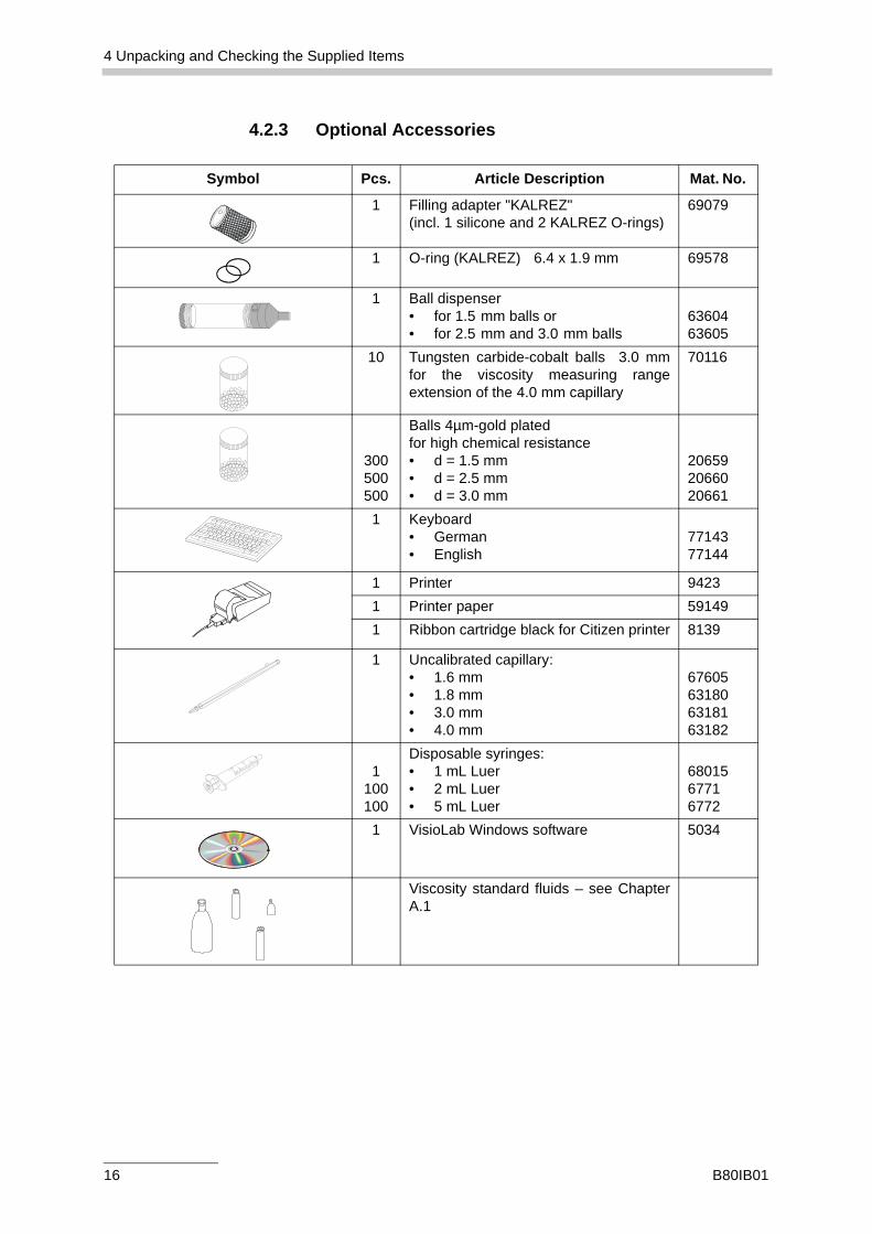
4.2.3 Optional Accessories
Symbol Pcs. Article Description Mat. No.
1 Filling adapter "KALREZ" (incl. 1 silicone and 2 KALREZ O-rings)
69079
1 O-ring (KALREZ) 6.4 x 1.9 mm 69578
1 Ball dispenser• for 1.5 mm balls or• for 2.5 mm and 3.0 mm balls
6360463605
10 Tungsten carbide-cobalt balls 3.0 mmfor the viscosity measuring rangeextension of the 4.0 mm capillary
70116
300500500
Balls 4µm-gold platedfor high chemical resistance• d = 1.5 mm• d = 2.5 mm• d = 3.0 mm
206592066020661
1 Keyboard• German• English
7714377144
1 Printer 94231 Printer paper 591491 Ribbon cartridge black for Citizen printer 8139
1 Uncalibrated capillary:• 1.6 mm• 1.8 mm• 3.0 mm• 4.0 mm
67605631806318163182
1100100
Disposable syringes:• 1 mL Luer• 2 mL Luer• 5 mL Luer
6801567716772
1 VisioLab Windows software 5034
Viscosity standard fluids – see ChapterA.1
16 B80IB01
5 Functional Components
5 Functional Components
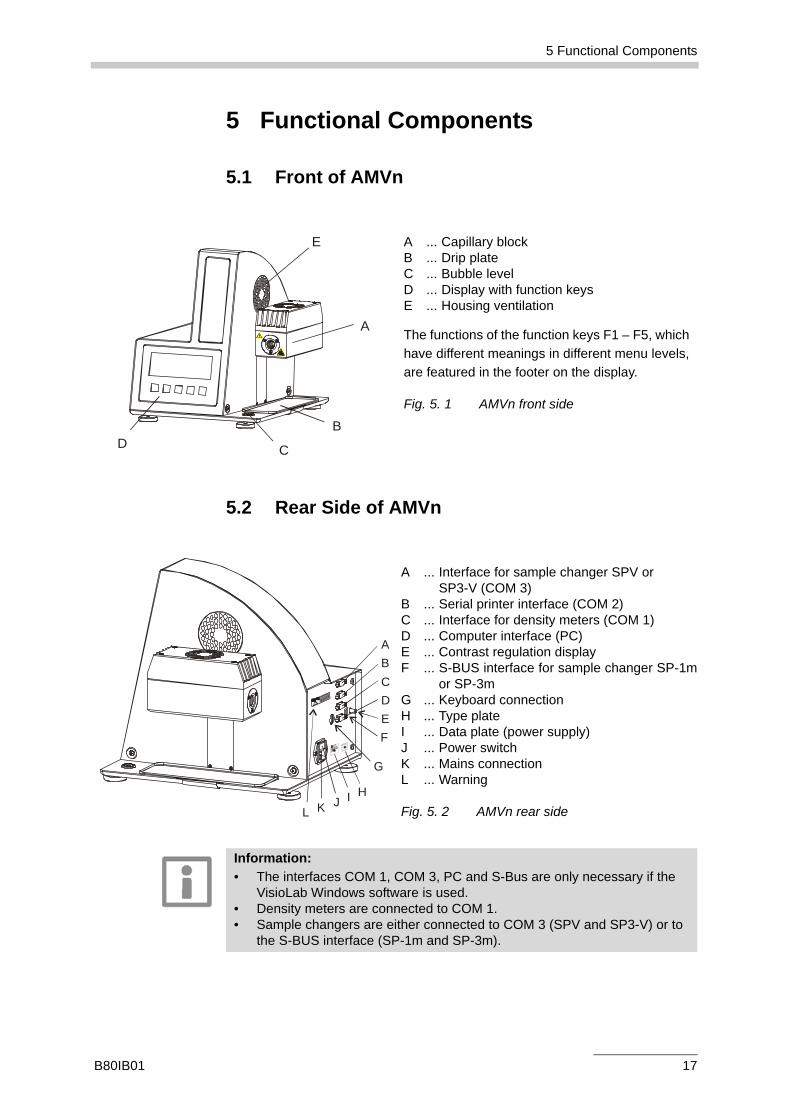
5.1 Front of AMVn
5.2 Rear Side of AMVn
A ... Capillary blockB ... Drip plateC ... Bubble levelD ... Display with function keysE ... Housing ventilation
The functions of the function keys F1 – F5, whichhave different meanings in different menu levels,are featured in the footer on the display.
Fig. 5. 1 AMVn front side
A
E
B
CD
A ... Interface for sample changer SPV or SP3-V (COM 3)
B ... Serial printer interface (COM 2)C ... Interface for density meters (COM 1)D ... Computer interface (PC)E ... Contrast regulation displayF ... S-BUS interface for sample changer SP-1m
or SP-3mG ... Keyboard connectionH ... Type plateI ... Data plate (power supply)J ... Power switchK ... Mains connectionL ... Warning
Fig. 5. 2 AMVn rear side
ABCDEF
G
HIJKL
Information:• The interfaces COM 1, COM 3, PC and S-Bus are only necessary if the
VisioLab Windows software is used. • Density meters are connected to COM 1. • Sample changers are either connected to COM 3 (SPV and SP3-V) or to
the S-BUS interface (SP-1m and SP-3m).
B80IB01 17
5 Functional Components
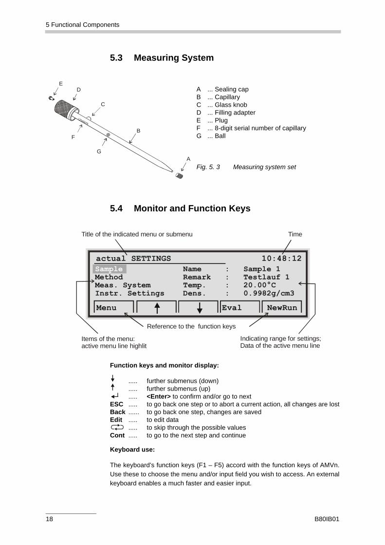
5.3 Measuring System
5.4 Monitor and Function Keys
Function keys and monitor display:
..... further submenus (down)..... further submenus (up)..... <Enter> to confirm and/or go to next
ESC ..... to go back one step or to abort a current action, all changes are lostBack ...... to go back one step, changes are savedEdit ..... to edit data
..... to skip through the possible valuesCont ..... to go to the next step and continue
Keyboard use:
The keyboard’s function keys (F1 – F5) accord with the function keys of AMVn.Use these to choose the menu and/or input field you wish to access. An externalkeyboard enables a much faster and easier input.
A ... Sealing capB ... CapillaryC ... Glass knobD ... Filling adapterE ... PlugF ... 8-digit serial number of capillaryG ... Ball
Fig. 5. 3 Measuring system set
C
A
ED
G
FB
actual SETTINGS 10:48:12Sample Name : Sample 1Method Remark : Testlauf 1Meas. System Temp. : 20.00°CInstr. Settings Dens. : 0.9982g/cm3
Menu Eval NewRun
Title of the indicated menu or submenu Time
Items of the menu:active menu line highlit
Reference to the function keys
Indicating range for settings;Data of the active menu line
18 B80IB01
6 Putting AMVn into Operation
6 Putting AMVn into OperationAMVn needs to be set up on a stable, level surface. To ensure temperaturestability, never locate AMVn:
• next to a heating facility• near an air conditioning or ventilation system • in direct sunlight.
6.1 Activating AMVn
1. Set up AMVn on the lab desk and level it off with the adjustable feet and thebuilt-in bubble level. Make sure all four feet touch the lab desk.
2. Connect the power inlet of the AMVn instrument to the mains using thedelivered power cord.
3. Activate AMVn with the power switch located on its rear side. The greendisplay light signals that the power is on.
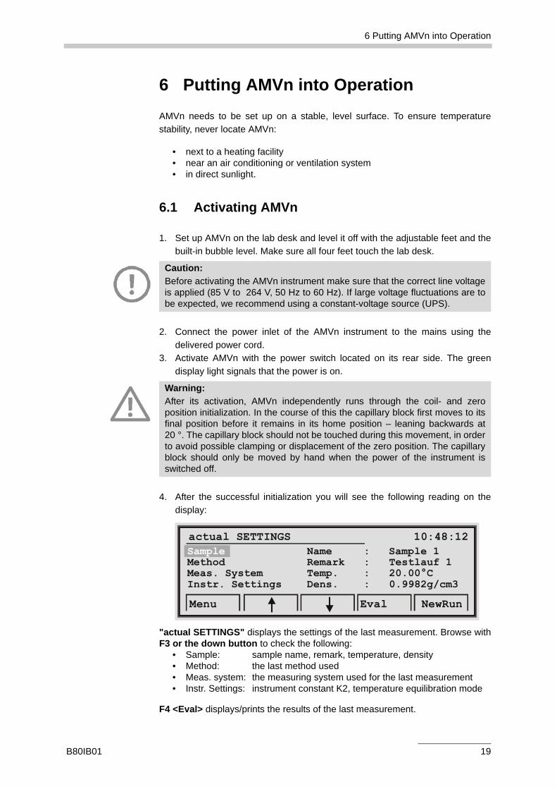
4. After the successful initialization you will see the following reading on thedisplay:
"actual SETTINGS" displays the settings of the last measurement. Browse withF3 or the down button to check the following:
• Sample: sample name, remark, temperature, density• Method: the last method used• Meas. system: the measuring system used for the last measurement• Instr. Settings: instrument constant K2, temperature equilibration mode
F4 <Eval> displays/prints the results of the last measurement.
Caution:Before activating the AMVn instrument make sure that the correct line voltageis applied (85 V to 264 V, 50 Hz to 60 Hz). If large voltage fluctuations are tobe expected, we recommend using a constant-voltage source (UPS).
Warning:After its activation, AMVn independently runs through the coil- and zeroposition initialization. In the course of this the capillary block first moves to itsfinal position before it remains in its home position – leaning backwards at20 °. The capillary block should not be touched during this movement, in orderto avoid possible clamping or displacement of the zero position. The capillaryblock should only be moved by hand when the power of the instrument isswitched off.
actual SETTINGS 10:48:12Sample Name : Sample 1Method Remark : Testlauf 1Meas. System Temp. : 20.00°CInstr. Settings Dens. : 0.9982g/cm3
Menu Eval NewRun
B80IB01 19
6 Putting AMVn into Operation
6.2 Preparing the Measurement
Before starting a measurement, fill the capillary and mount the measuring systemin the capillary block.
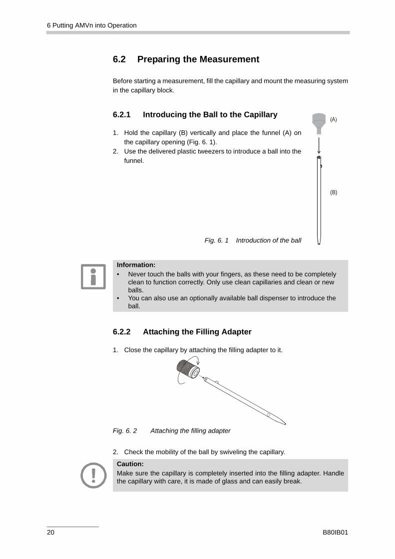
6.2.1 Introducing the Ball to the Capillary
1. Hold the capillary (B) vertically and place the funnel (A) onthe capillary opening (Fig. 6. 1).
2. Use the delivered plastic tweezers to introduce a ball into thefunnel.
Fig. 6. 1 Introduction of the ball
6.2.2 Attaching the Filling Adapter
1. Close the capillary by attaching the filling adapter to it.
Fig. 6. 2 Attaching the filling adapter
2. Check the mobility of the ball by swiveling the capillary.
(B)
Information:• Never touch the balls with your fingers, as these need to be completely
clean to function correctly. Only use clean capillaries and clean or new balls.
• You can also use an optionally available ball dispenser to introduce the ball.
Caution:Make sure the capillary is completely inserted into the filling adapter. Handlethe capillary with care, it is made of glass and can easily break.
20 B80IB01
6 Putting AMVn into Operation
6.2.3 Filling the Capillary
1. Introduce a syringe into the cone of the filling adapter.2. Immerse the tip of the capillary in the sample.3. Draw up the sample with the syringe until it is visible in the
lower end of the syringe. The capillary should be completelyfree of air bubbles, otherwise the filling procedure needs to berepeated.
4. Dry the tip of the capillary with a cloth and close it with a LUERcap.
5. Now extract the syringe from the filling adapter and dry theadapter if necessary. Close the filling adapter with the LUERplug.
6. Make sure that the capillary’s exterior is clean and dry.7. Again check the mobility of the ball by swiveling the capillary.
Fig. 6. 3 Filling the capillary
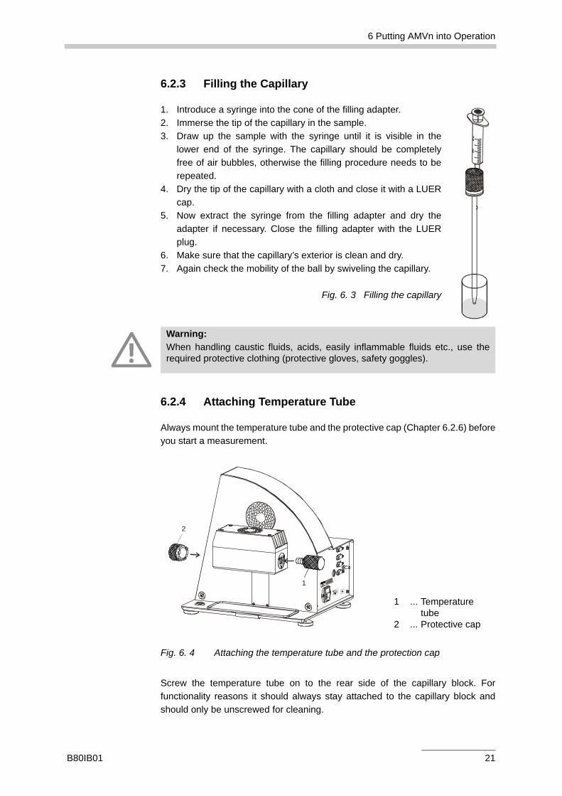
6.2.4 Attaching Temperature Tube
Always mount the temperature tube and the protective cap (Chapter 6.2.6) beforeyou start a measurement.
Fig. 6. 4 Attaching the temperature tube and the protection cap
Screw the temperature tube on to the rear side of the capillary block. Forfunctionality reasons it should always stay attached to the capillary block andshould only be unscrewed for cleaning.
Warning:When handling caustic fluids, acids, easily inflammable fluids etc., use therequired protective clothing (protective gloves, safety goggles).
1 ... Temperaturetube
2 ... Protective cap
1
2
B80IB01 21
6 Putting AMVn into Operation
6.2.5 Mounting the Capillary into the AMVn Instrument
Before mounting the filled capillary, you need to activate AMVn and wait until theself-test is concluded (Chapter 6.1).
1. Carefully insert the capillary into the capillary block, starting from the front. 2. Turn the capillary so that the glass knob easily slips into the corresponding
recess of the capillary block opening.
As soon as the glass knob has slid into the opening, completely insert the capillaryinto the capillary block until the red silicone O-ring of the adapter is no longervisible and you meet a resistance.
6.2.6 Attaching Protective Cap
1. After mounting a capillary, attach the protective cap (2, Fig. 6. 4) in a straightposition in the front of the capillary block.
2. Fix the protective cap by turning it clockwise.
Leave the protective cap on the capillary block during the measurement and onlyremove it once you change the capillary.
Caution:Make sure that the self-test is concluded and no measurement program hasstarted, so that the capillary block does not start any surprising movements.Do not push too hard when mounting the capillary, because the glass couldbreak. Do not use excessive force!
Hot surface:When attaching or removing the temperature tube and the protective cap athigh measuring temperatures you might be operating in the direct vicinity ofhot surfaces. Therefore only touch the capillary block and the capillary withadequate protective gloves (Chapter 2.2) or wait until the capillary block hascooled down.
Warning:If the samples in the capillary are heated up to measuring temperatures up to135 °C, the thermal expansion of the fluid in the glass capillary may result inthe unintentional opening of the capillary’s sealing caps. It is imperative to usethe temperature tube and the protective cap.
22 B80IB01
7 Measurement
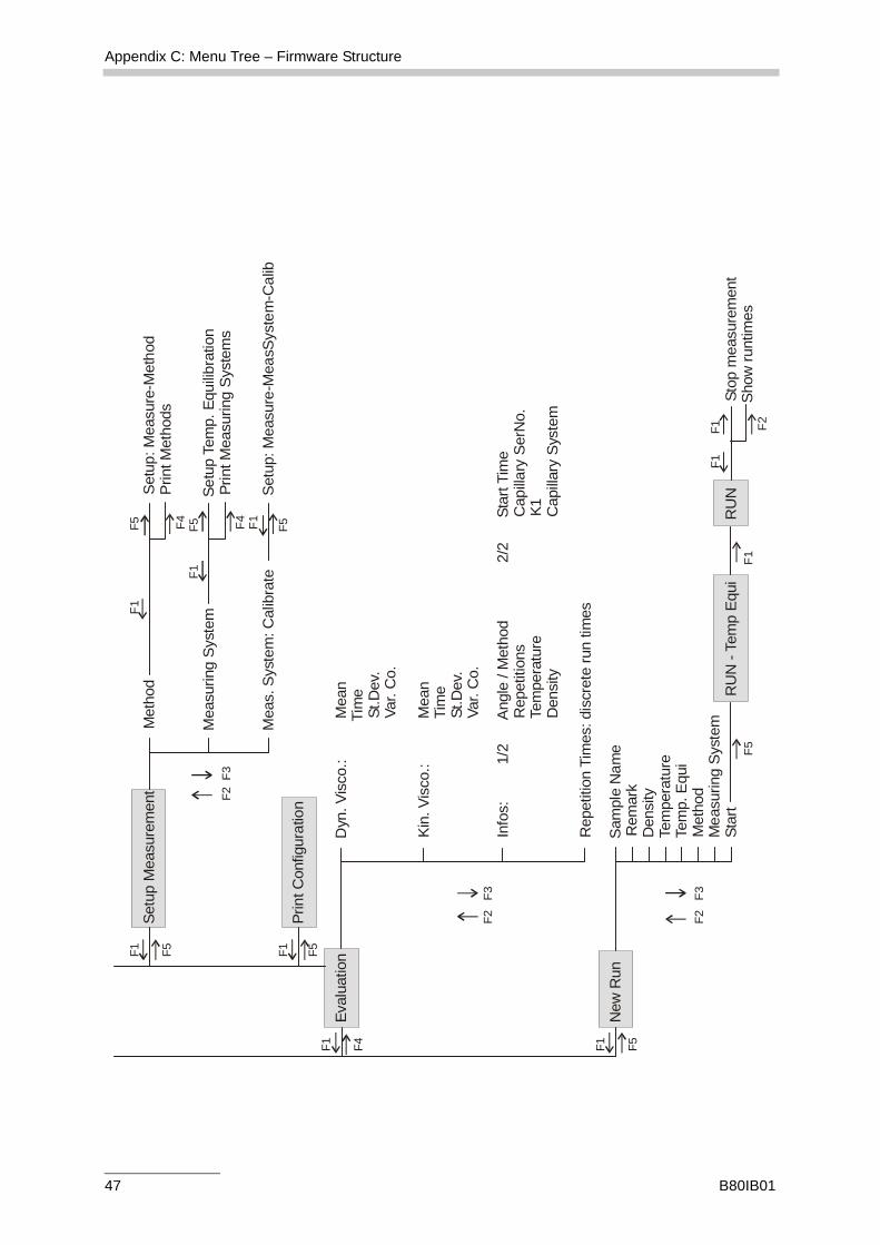
7 MeasurementBefore starting a measurement, set up AMVn according to your wishes.
7.1 Setting up AMVn
To prepare a measurement, press F5 <New Run> in the main menu "ActualSettings" which appears after activation.
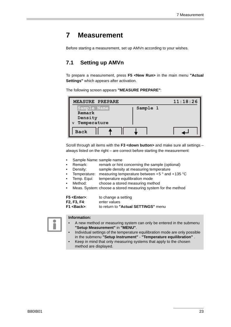
The following screen appears "MEASURE PREPARE":
Scroll through all items with the F3 <down button> and make sure all settings –always listed on the right – are correct before starting the measurement:
• Sample Name: sample name• Remark: remark or hint concerning the sample (optional)• Density: sample density at measuring temperature• Temperature: measuring temperature between +5 ° and +135 °C• Temp. Equi: temperature equilibration mode• Method: choose a stored measuring method• Meas. System: choose a stored measuring system for the method
F5 <Enter>: to change a settingF2, F3, F4: enter valuesF1 <Back>: to return to "Actual SETTINGS" menu
MEASURE PREPARE 11:18:26Sample Name Sample 1RemarkDensityTemperature
Back
V
Information:• A new method or measuring system can only be entered in the submenu
"Setup Measurement" in "MENU".• Individual settings of the temperature equilibration mode are only possible
in the submenu "Setup Instrument" - "Temperature equilibration" .• Keep in mind that only measuring systems that apply to the chosen
method are displayed.
B80IB01 23
7 Measurement
7.2 Starting the Measurement
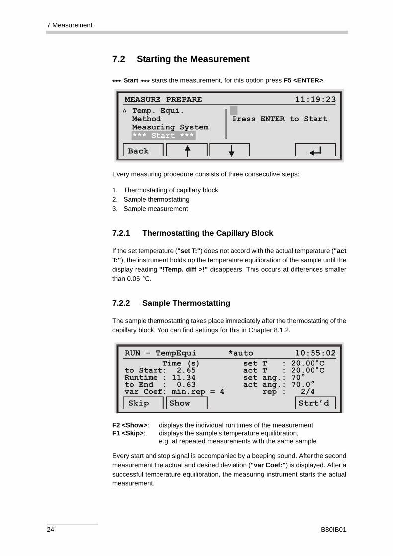
*** Start *** starts the measurement, for this option press F5 <ENTER>.
Every measuring procedure consists of three consecutive steps:
1. Thermostatting of capillary block2. Sample thermostatting3. Sample measurement
7.2.1 Thermostatting the Capillary Block
If the set temperature ("set T:") does not accord with the actual temperature ("actT:"), the instrument holds up the temperature equilibration of the sample until thedisplay reading "!Temp. diff >!" disappears. This occurs at differences smallerthan 0.05 °C.
7.2.2 Sample Thermostatting
The sample thermostatting takes place immediately after the thermostatting of thecapillary block. You can find settings for this in Chapter 8.1.2.
F2 <Show>: displays the individual run times of the measurementF1 <Skip>: displays the sample’s temperature equilibration,
e.g. at repeated measurements with the same sample
Every start and stop signal is accompanied by a beeping sound. After the secondmeasurement the actual and desired deviation ("var Coef:") is displayed. After asuccessful temperature equilibration, the measuring instrument starts the actualmeasurement.
MEASURE PREPARE 11:19:23
Back
V Temp. Equi.Method Press ENTER to StartMeasuring System*** Start ***
RUN - TempEqui *auto 10:55:02 Time (s) set T : 20.00°Cto Start: 2.65 act T : 20.00°CRuntime : 11.34 set ang.: 70°to End : 0.63 act ang.: 70.0°var Coef: min.rep = 4 rep : 2/4
Skip Show Strt’d
24 B80IB01
7 Measurement
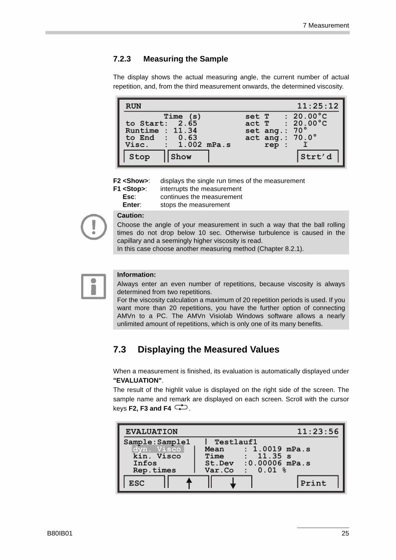
7.2.3 Measuring the Sample
The display shows the actual measuring angle, the current number of actualrepetition, and, from the third measurement onwards, the determined viscosity.
F2 <Show>: displays the single run times of the measurementF1 <Stop>: interrupts the measurement
Esc: continues the measurement Enter: stops the measurement
7.3 Displaying the Measured Values
When a measurement is finished, its evaluation is automatically displayed under"EVALUATION".The result of the highlit value is displayed on the right side of the screen. Thesample name and remark are displayed on each screen. Scroll with the cursorkeys F2, F3 and F4 .
RUN 11:25:12 Time (s) set T : 20.00°Cto Start: 2.65 act T : 20.00°CRuntime : 11.34 set ang.: 70°to End : 0.63 act ang.: 70.0°Visc. : 1.002 mPa.s rep : ľ
Stop Show Strt’d
Caution:Choose the angle of your measurement in such a way that the ball rollingtimes do not drop below 10 sec. Otherwise turbulence is caused in thecapillary and a seemingly higher viscosity is read. In this case choose another measuring method (Chapter 8.2.1).
Information:Always enter an even number of repetitions, because viscosity is alwaysdetermined from two repetitions.For the viscosity calculation a maximum of 20 repetition periods is used. If youwant more than 20 repetitions, you have the further option of connectingAMVn to a PC. The AMVn Visiolab Windows software allows a nearlyunlimited amount of repetitions, which is only one of its many benefits.
EVALUATION 11:23:56Sample:Sample1 Testlauf1 Mean : 1.0019 mPa.sdyn. Visco kin. Visco Time : 11.35 s Infos St.Dev :0.00006 mPa.s Rep.times Var.Co : 0.01 %
ESC Print
B80IB01 25
7 Measurement
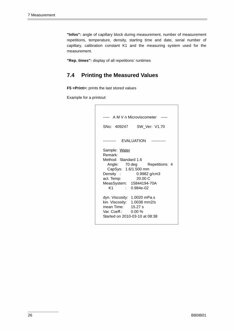
"Infos": angle of capillary block during measurement, number of measurementrepetitions, temperature, density, starting time and date, serial number ofcapillary, calibration constant K1 and the measuring system used for themeasurement.
"Rep. times": display of all repetitions’ runtimes
7.4 Printing the Measured Values
F5 <Print>: prints the last stored values
Example for a printout:
----- A M V n Microviscometer -----
SNo: 409247 SW_Ver: V1.70
---------- EVALUATION -----------
Sample: WaterRemark:Method: Standard 1.6 Angle: 70 deg Repetitions: 4 CapSys: 1.6/1.500 mmDensity : 0.9982 g/cm3act. Temp: 20.00 CMeasSystem: 15844194-70A
K1 : 0.984e-02
dyn. Viscosity: 1.0020 mPa.skin. Viscosity: 1.0038 mm2/smean Time: 15.27 sVar. Coeff.: 0.00 %Started on 2010-03-10 at 08:38
26 B80IB01
7 Measurement
7.5 Cleaning the Measuring System
A thorough cleaning of the AMVn measuring system after measurementconclusion is imperative.
1. Remove the protective cap.2. Remove the capillary from the the capillary block. Take care not to twist the
capillary.3. Remove the LUER plug and insert a syringe into the filling adapter.4. Now remove the LUER cap and rinse the capillary with cleaning agent.
Repeat the rinsing procedure several times by drawing up and flushing outcleaning agent.
5. After the cleaning procedure remove the syringe and the filling adapter.6. Use a volatile solvent, e.g. highly concentrated alcohol or acetone, to
accelerate the drying procedure after cleaning.7. Dry the measuring system e.g. with compressed air (max. 0.5 bar).8. Check that the ball moves easily when the capillary is swiveled. If this is the
case, the cleaning procedure is concluded.
Caution:• Do not leave any samples in the measuring system after you have
finished the measurement. • Rinse the measuring system with a suitable cleaning agent.• Only use cleaning agents that are compatible with the materials (Chapter
10.4).• Before you dry the capillary with compressed air, remove the ball.
B80IB01 27
8 AMVn Firmware Update
8 AMVn Firmware Update This description extends to the Firmware Version V1.7x. If your AMVn featuresanother Firmware Version, minor differences to the description in this manualcould occur.
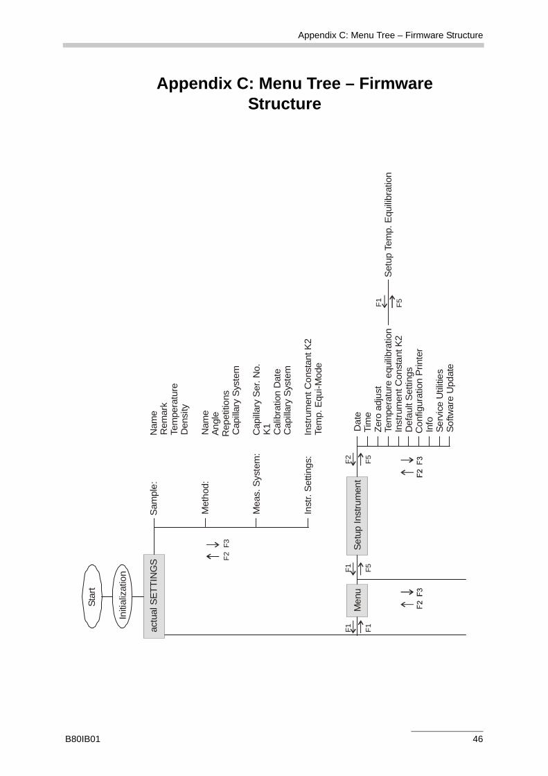
Through the main menu "MENU" you access the submenus:
• "Setup Instrument" for setting up AMVn,• "SETUP Measurement" to enter measurement settings and• "Print Configuration" to print out the configuration of AMVn.
8.1 Menu – "SETUP Instrument"
In "Setup Instrument" you can view or change all settings concerning AMVn.With F5 <Enter> you can access each of the following submenus, with F1 <Backor <ESC> you return to the menu.
• "Date" – Date• "Time" – Time• "Zero adjust" – Zero adjustment• "Temperature equilibration" – Temperature equilibration• "Instrument Constant K2" – Instrument constant: preset• "Default Settings" – Default settings• "Configuration Printer" – Printer configuration• "Info" – Information on Firmware Version, serial number of AMVn and your
Anton Paar GmbH contact address• "Service Utilities" – password-protected service menu for authorized
service personnel of Anton Paar GmbH • "Software Update" – Update instrument software
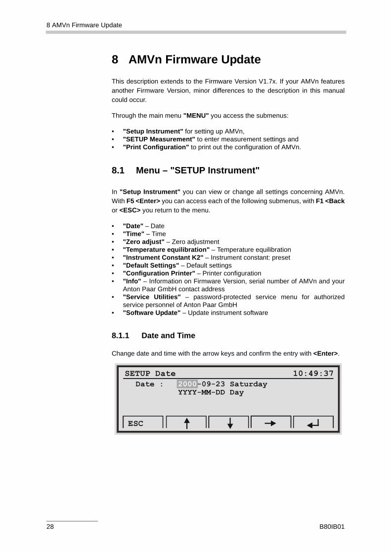
8.1.1 Date and Time
Change date and time with the arrow keys and confirm the entry with <Enter>.
SETUP Date 10:49:37Date : Saturday YYYY-MM-DD Day
2000-09-23
ESC
28 B80IB01
8 AMVn Firmware Update
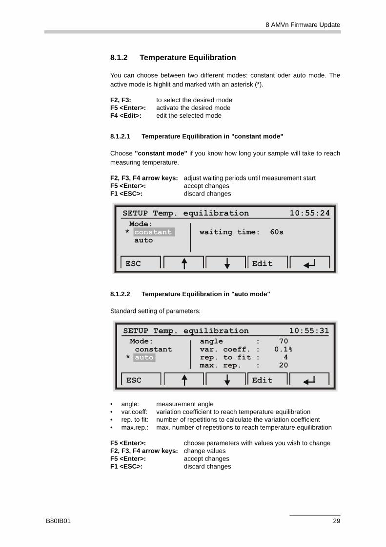
8.1.2 Temperature Equilibration
You can choose between two different modes: constant oder auto mode. Theactive mode is highlit and marked with an asterisk (*).
F2, F3: to select the desired mode F5 <Enter>: activate the desired modeF4 <Edit>: edit the selected mode
8.1.2.1 Temperature Equilibration in "constant mode"
Choose "constant mode" if you know how long your sample will take to reachmeasuring temperature.
F2, F3, F4 arrow keys: adjust waiting periods until measurement startF5 <Enter>: accept changesF1 <ESC>: discard changes
8.1.2.2 Temperature Equilibration in "auto mode"
Standard setting of parameters:
• angle: measurement angle• var.coeff: variation coefficient to reach temperature equilibration• rep. to fit: number of repetitions to calculate the variation coefficient• max.rep.: max. number of repetitions to reach temperature equilibration
F5 <Enter>: choose parameters with values you wish to changeF2, F3, F4 arrow keys: change valuesF5 <Enter>: accept changesF1 <ESC>: discard changes
SETUP Temp. equilibration 10:55:24 Mode:* waiting time: 60s auto
constant
ESC Edit
SETUP Temp. equilibration 10:55:31 Mode: angle : 70 constant var. coeff. : 0.1%* auto rep. to fit : 4 max. rep. : 20
ESC Edit
B80IB01 29
8 AMVn Firmware Update
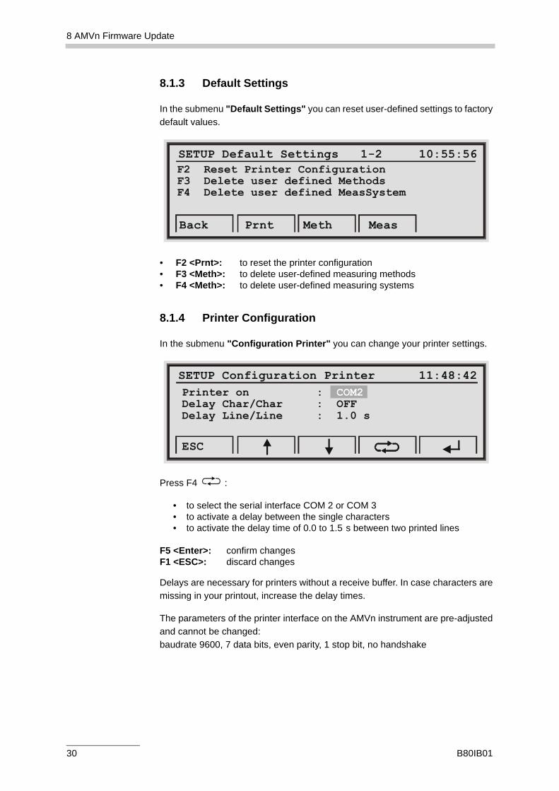
8.1.3 Default Settings
In the submenu "Default Settings" you can reset user-defined settings to factorydefault values.
• F2 <Prnt>: to reset the printer configuration• F3 <Meth>: to delete user-defined measuring methods• F4 <Meth>: to delete user-defined measuring systems
8.1.4 Printer Configuration
In the submenu "Configuration Printer" you can change your printer settings.
Press F4 :
• to select the serial interface COM 2 or COM 3• to activate a delay between the single characters• to activate the delay time of 0.0 to 1.5 s between two printed lines
F5 <Enter>: confirm changesF1 <ESC>: discard changes
Delays are necessary for printers without a receive buffer. In case characters aremissing in your printout, increase the delay times.
The parameters of the printer interface on the AMVn instrument are pre-adjustedand cannot be changed: baudrate 9600, 7 data bits, even parity, 1 stop bit, no handshake
SETUP Default Settings 1-2 10:55:56F2 Reset Printer ConfigurationF3 Delete user defined MethodsF4 Delete user defined MeasSystem
Back Prnt Meth Meas
SETUP Configuration Printer 11:48:42Printer on : Delay Char/Char : OFFDelay Line/Line : 1.0 s
COM2
ESC
30 B80IB01
8 AMVn Firmware Update
8.1.5 Software Update
In the submenu "Software Update" you can install new instrument softwareversions. Further information will be included with your update.
Whenever applicable, contact your local Anton Paar representative for possiblefirmware updates.
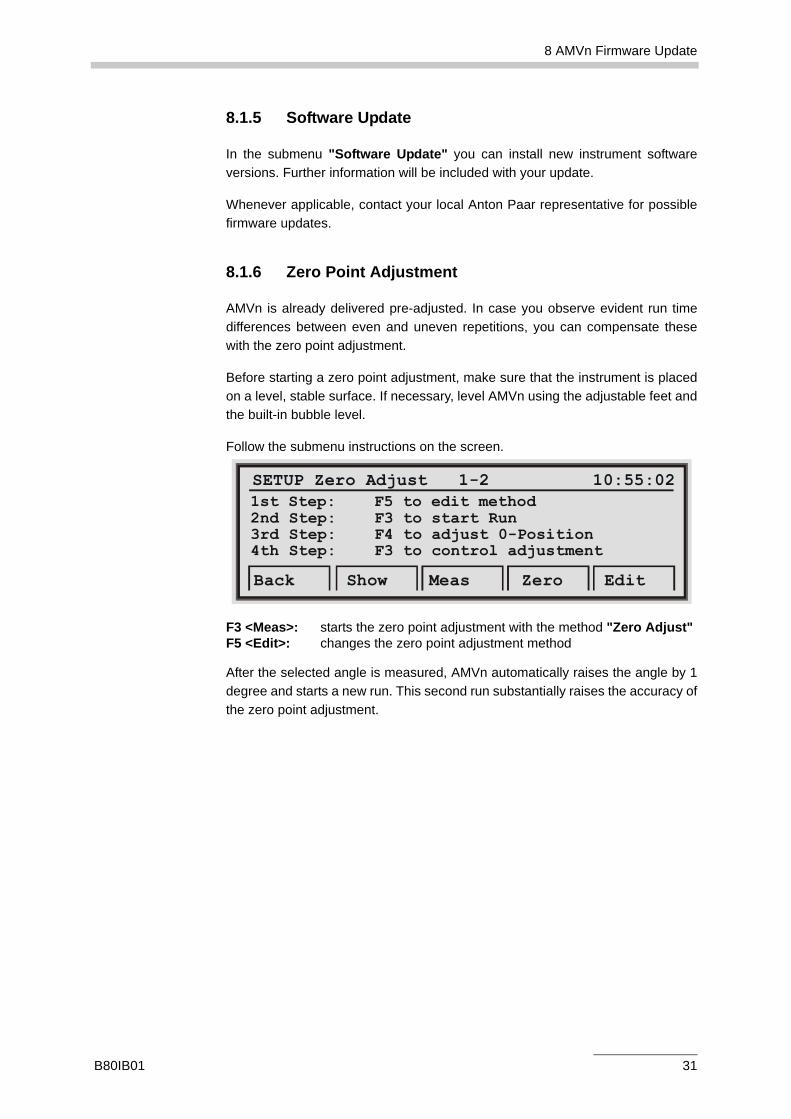
8.1.6 Zero Point Adjustment
AMVn is already delivered pre-adjusted. In case you observe evident run timedifferences between even and uneven repetitions, you can compensate thesewith the zero point adjustment.
Before starting a zero point adjustment, make sure that the instrument is placedon a level, stable surface. If necessary, level AMVn using the adjustable feet andthe built-in bubble level.
Follow the submenu instructions on the screen.
F3 <Meas>: starts the zero point adjustment with the method "Zero Adjust" F5 <Edit>: changes the zero point adjustment method
After the selected angle is measured, AMVn automatically raises the angle by 1degree and starts a new run. This second run substantially raises the accuracy ofthe zero point adjustment.
SETUP Zero Adjust 1-2 10:55:021st Step: F5 to edit method2nd3rd4th
Step: F3 to start Run Step: F4 to adjust 0-Position Step: F3 to control adjustment
Back Show Meas Zero Edit
B80IB01 31
8 AMVn Firmware Update
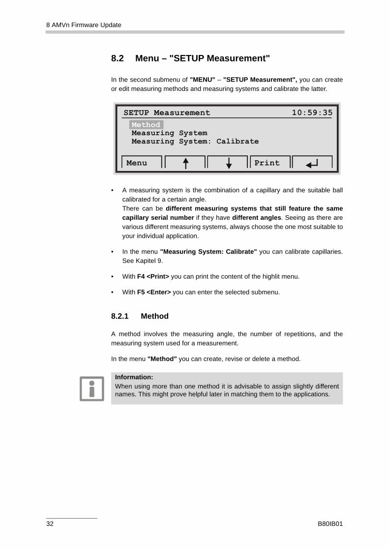
8.2 Menu – "SETUP Measurement"
In the second submenu of "MENU" – "SETUP Measurement", you can createor edit measuring methods and measuring systems and calibrate the latter.
• A measuring system is the combination of a capillary and the suitable ballcalibrated for a certain angle. There can be different measuring systems that still feature the samecapillary serial number if they have different angles. Seeing as there arevarious different measuring systems, always choose the one most suitable toyour individual application.
• In the menu "Measuring System: Calibrate" you can calibrate capillaries.See Kapitel 9.
• With F4 <Print> you can print the content of the highlit menu.
• With F5 <Enter> you can enter the selected submenu.
8.2.1 Method
A method involves the measuring angle, the number of repetitions, and themeasuring system used for a measurement.
In the menu "Method" you can create, revise or delete a method.
SETUP Measurement 10:59:35MethodMeasuring SystemMeasuring System: Calibrate
Menu Print
Information:When using more than one method it is advisable to assign slightly differentnames. This might prove helpful later in matching them to the applications.
32 B80IB01
8 AMVn Firmware Update
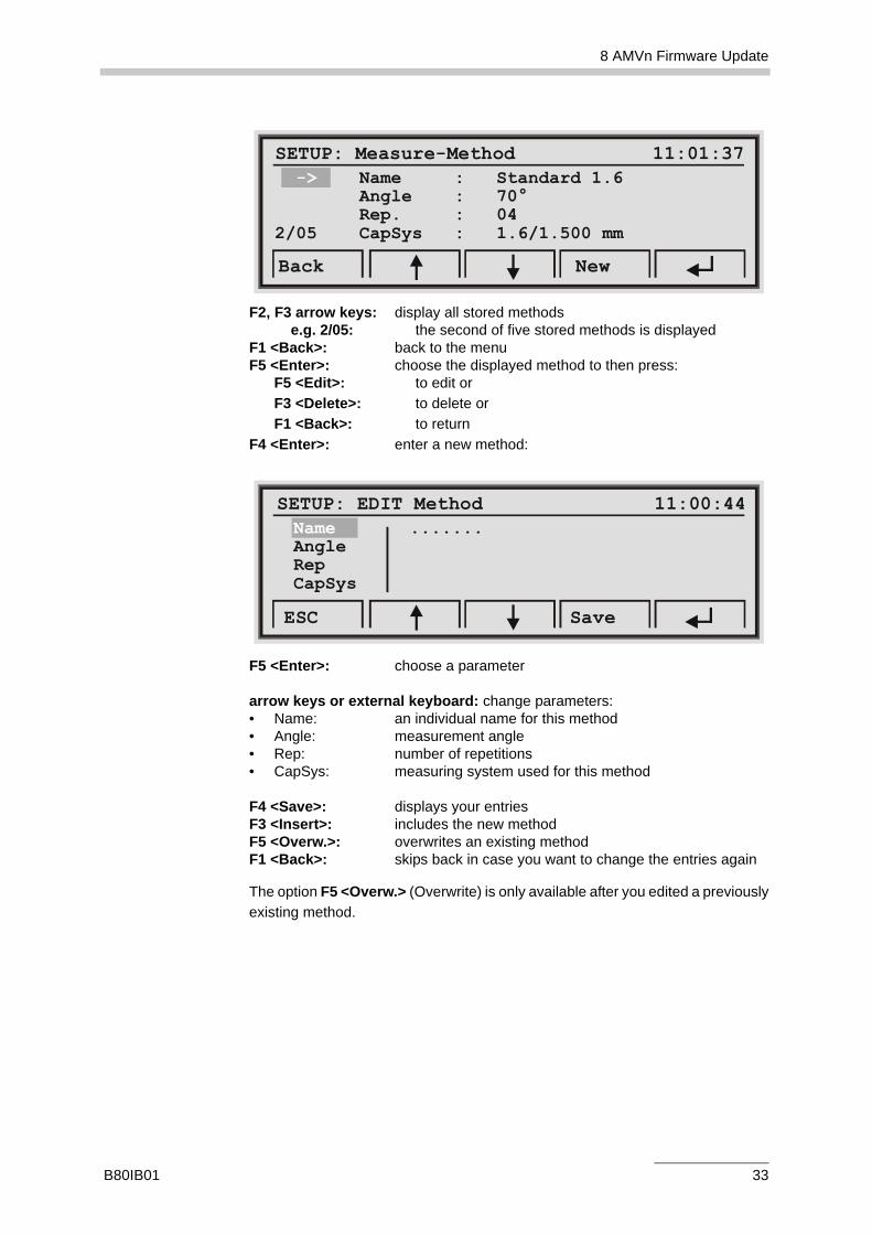
F2, F3 arrow keys: display all stored methodse.g. 2/05: the second of five stored methods is displayed
F1 <Back>: back to the menuF5 <Enter>: choose the displayed method to then press:
F5 <Edit>: to edit orF3 <Delete>: to delete orF1 <Back>: to return
F4 <Enter>: enter a new method:
F5 <Enter>: choose a parameter
arrow keys or external keyboard: change parameters:• Name: an individual name for this method• Angle: measurement angle• Rep: number of repetitions• CapSys: measuring system used for this method
F4 <Save>: displays your entriesF3 <Insert>: includes the new method F5 <Overw.>: overwrites an existing method F1 <Back>: skips back in case you want to change the entries again
The option F5 <Overw.> (Overwrite) is only available after you edited a previouslyexisting method.
SETUP: Measure-Method 11:01:37 -> Name : Standard 1.6 Angle : 70° Rep. : 042/05 CapSys : 1.6/1.500 mm
Back New
SETUP: EDIT Method 11:00:44Name .......AngleRepCapSys
ESC Save
B80IB01 33
8 AMVn Firmware Update
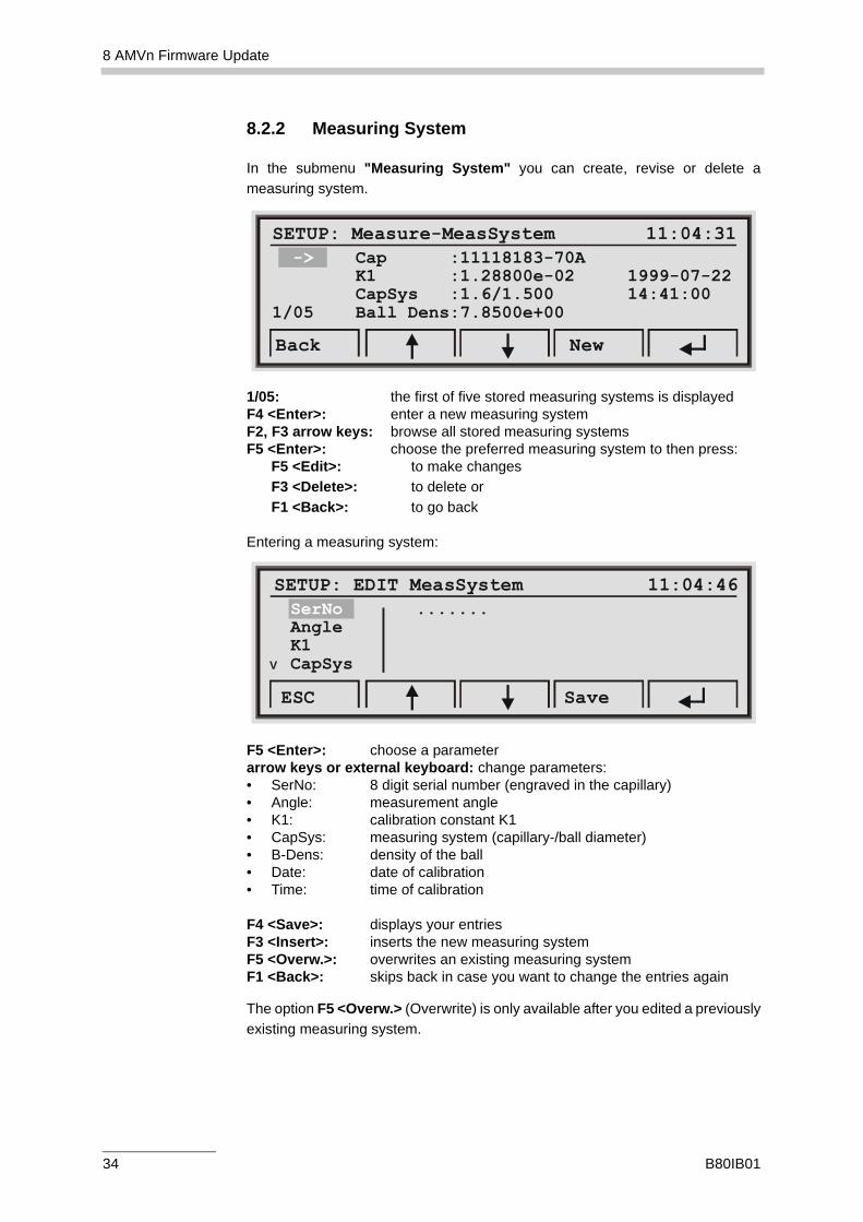
8.2.2 Measuring System
In the submenu "Measuring System" you can create, revise or delete ameasuring system.
1/05: the first of five stored measuring systems is displayedF4 <Enter>: enter a new measuring system F2, F3 arrow keys: browse all stored measuring systemsF5 <Enter>: choose the preferred measuring system to then press:
F5 <Edit>: to make changes F3 <Delete>: to delete orF1 <Back>: to go back
Entering a measuring system:
F5 <Enter>: choose a parameterarrow keys or external keyboard: change parameters:• SerNo: 8 digit serial number (engraved in the capillary)• Angle: measurement angle• K1: calibration constant K1• CapSys: measuring system (capillary-/ball diameter)• B-Dens: density of the ball• Date: date of calibration• Time: time of calibration
F4 <Save>: displays your entriesF3 <Insert>: inserts the new measuring system F5 <Overw.>: overwrites an existing measuring system F1 <Back>: skips back in case you want to change the entries again
The option F5 <Overw.> (Overwrite) is only available after you edited a previouslyexisting measuring system.
SETUP: Measure-MeasSystem 11:04:31 -> Cap :11118183-70A K1 :1.28800e-02 1999-07-22 :1.6/1.500 14:41:001/05 Ball Dens:7.8500e+00
CapSys
Back New
SETUP: EDIT MeasSystem 11:04:46SerNo .......AngleK1CapSys
ESC Save
V
34 B80IB01
8 AMVn Firmware Update
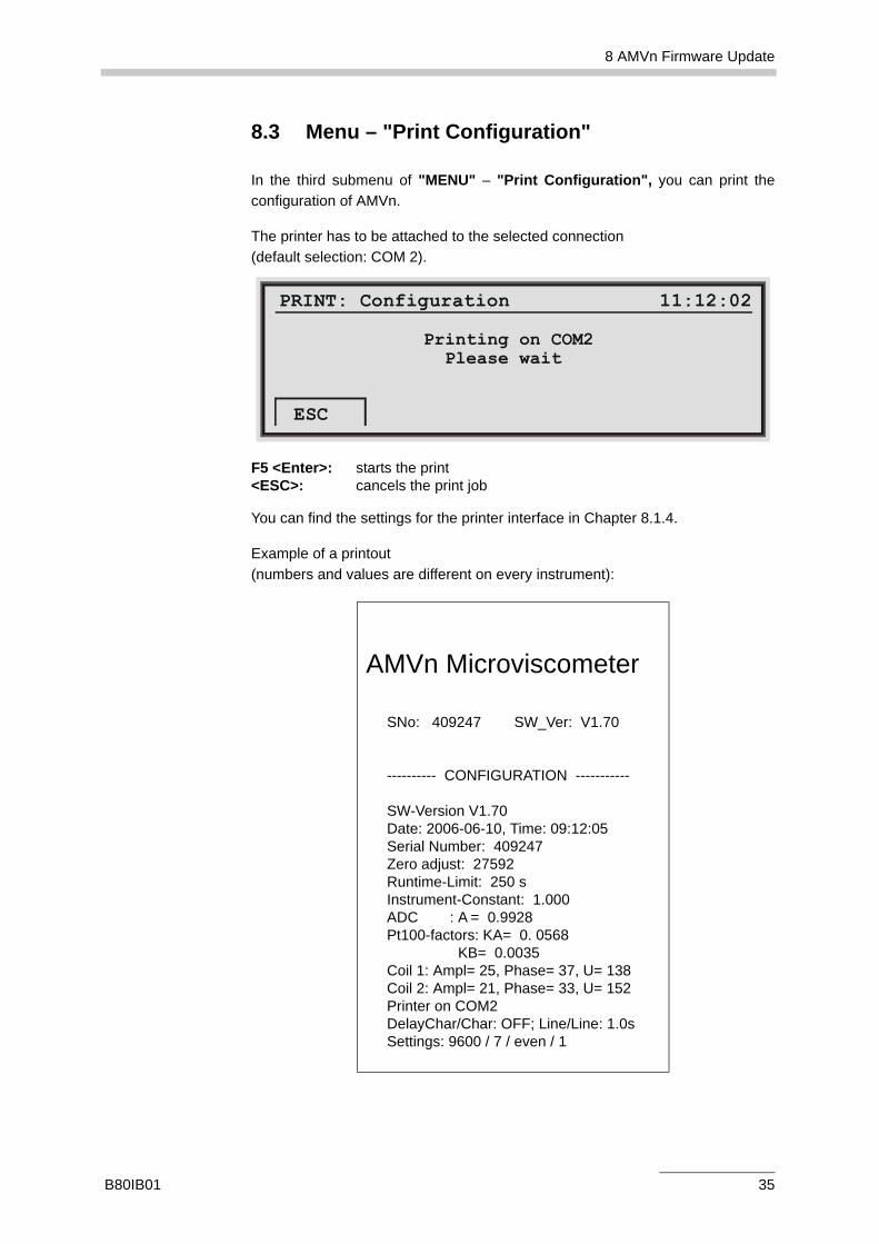
8.3 Menu – "Print Configuration"
In the third submenu of "MENU" – "Print Configuration", you can print theconfiguration of AMVn.
The printer has to be attached to the selected connection (default selection: COM 2).
F5 <Enter>: starts the print<ESC>: cancels the print job
You can find the settings for the printer interface in Chapter 8.1.4.
Example of a printout (numbers and values are different on every instrument):
AMVn Microviscometer
SNo: 409247 SW_Ver: V1.70
---------- CONFIGURATION -----------
SW-Version V1.70Date: 2006-06-10, Time: 09:12:05Serial Number: 409247Zero adjust: 27592Runtime-Limit: 250 sInstrument-Constant: 1.000ADC : A = 0.9928Pt100-factors: KA= 0. 0568
KB= 0.0035Coil 1: Ampl= 25, Phase= 37, U= 138Coil 2: Ampl= 21, Phase= 33, U= 152Printer on COM2DelayChar/Char: OFF; Line/Line: 1.0sSettings: 9600 / 7 / even / 1
PRINT: Configuration 11:12:02
Printing on COM2 Please wait
ESC
B80IB01 35
9 Calibration of Measuring Systems
9 Calibration of Measuring SystemsFor a precise viscosity determination, the calibration of the capillary is necessary.The calibration constant is different at every angle and with every capillary.
9.1 Calibrated and Uncalibrated Capillaries
There are calibrated and uncalibrated measuring system sets (Chapter 4.2.2) andcalibrated and uncalibrated capillaries:
• Calibrated capillary: calibrated at certain angles and a certain temperaturebefore delivery. The data is stored on a data medium and on the calibrationcertificate. Both is delivered. Manually enter the calibration constant datastated on the calibration certificate in the firmware, menu "SetupMeasurement" (also see Chapter 8.2). Import the calibration constant fromthe data medium in the Visiolab software.
• Uncalibrated capillary: determine the calibration constant acc. tocalibration procedure and store this value in the menu "SetupMeasurement" (Chapter 8.2).
When using a new or alternative ball set the calibration constant only needs tobe redefined in case the measuring deviation is above tolerance limit (0.3 %) and/or the ball set features a different batch number. Read the batch number on thesticker attached to your ball set.
When calibrating a measuring system, choose the viscosity standard in such away that it falls within the viscosity range of the measurement at the usualmeasuring temperature (Chapter A.1).
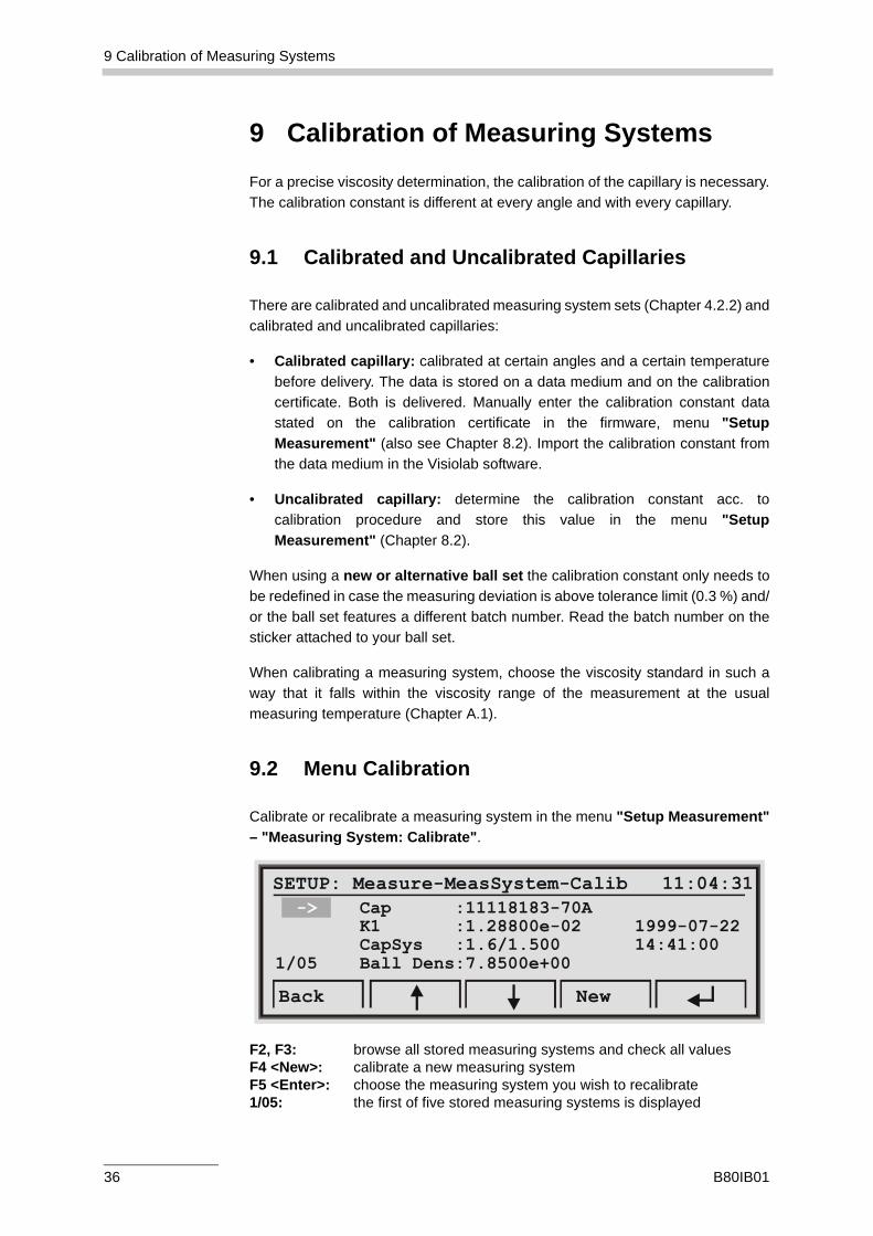
9.2 Menu Calibration
Calibrate or recalibrate a measuring system in the menu "Setup Measurement"– "Measuring System: Calibrate".
F2, F3: browse all stored measuring systems and check all valuesF4 <New>: calibrate a new measuring systemF5 <Enter>: choose the measuring system you wish to recalibrate1/05: the first of five stored measuring systems is displayed
SETUP: Measure-MeasSystem-Calib 11:04:31 -> Cap :11118183-70A K1 :1.28800e-02 1999-07-22 :1.6/1.500 14:41:001/05 Ball Dens:7.8500e+00
CapSys
Back New
36 B80IB01
9 Calibration of Measuring Systems
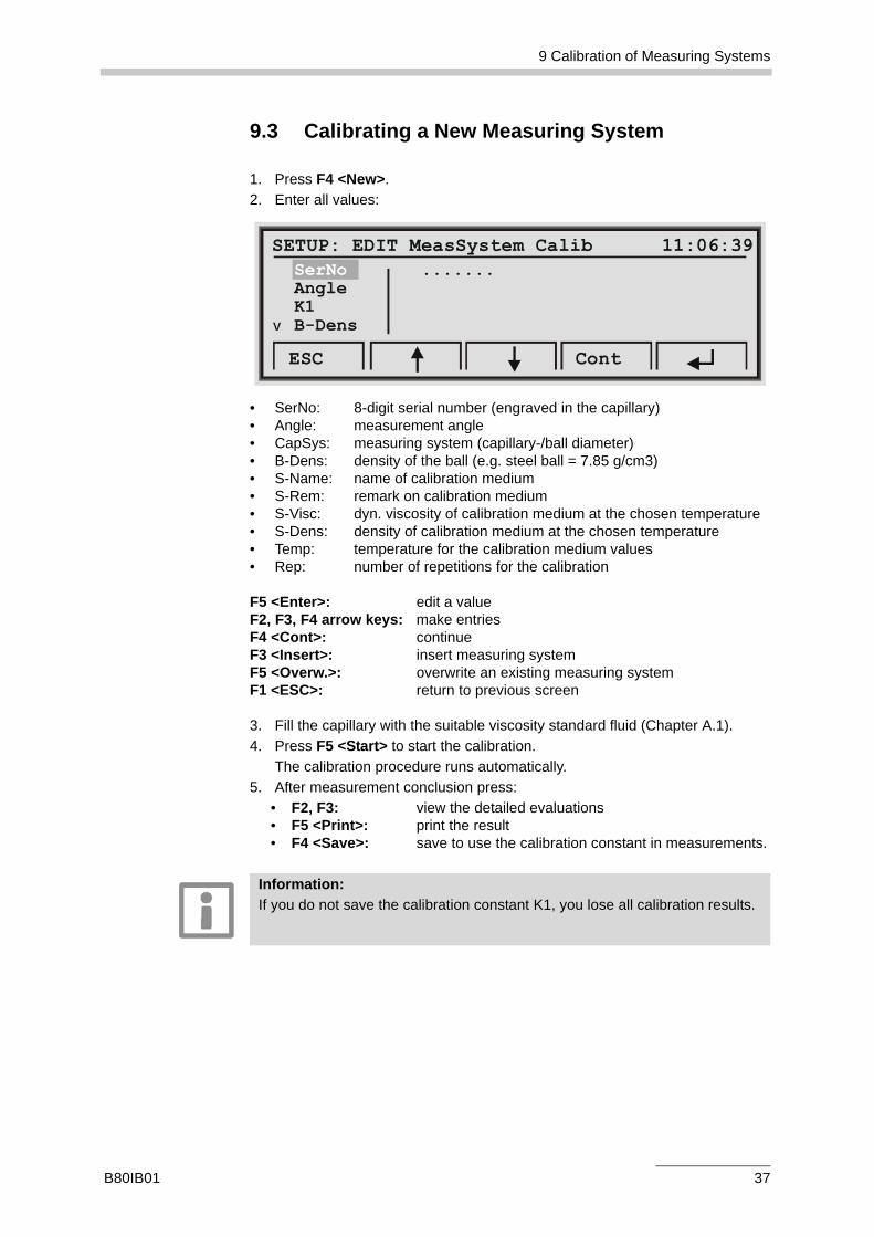
9.3 Calibrating a New Measuring System
1. Press F4 <New>. 2. Enter all values:
• SerNo: 8-digit serial number (engraved in the capillary)• Angle: measurement angle• CapSys: measuring system (capillary-/ball diameter)• B-Dens: density of the ball (e.g. steel ball = 7.85 g/cm3)• S-Name: name of calibration medium• S-Rem: remark on calibration medium• S-Visc: dyn. viscosity of calibration medium at the chosen temperature• S-Dens: density of calibration medium at the chosen temperature• Temp: temperature for the calibration medium values• Rep: number of repetitions for the calibration
F5 <Enter>: edit a value F2, F3, F4 arrow keys: make entriesF4 <Cont>: continueF3 <Insert>: insert measuring systemF5 <Overw.>: overwrite an existing measuring systemF1 <ESC>: return to previous screen
3. Fill the capillary with the suitable viscosity standard fluid (Chapter A.1).4. Press F5 <Start> to start the calibration.
The calibration procedure runs automatically.5. After measurement conclusion press:
• F2, F3: view the detailed evaluations • F5 <Print>: print the result • F4 <Save>: save to use the calibration constant in measurements.
SETUP: EDIT MeasSystem Calib 11:06:39SerNo .......AngleK1B-Dens
ESC Cont
V
Information:If you do not save the calibration constant K1, you lose all calibration results.
B80IB01 37
10 Maintenance
10 MaintenanceClean AMVn and its accessories regularly.
We recommend regular maintenance of your measuring instrument by authorizedAnton Paar GmbH personnel.
10.1 Cleaning the Measuring System
A thorough cleaning of the AMVn measuring system after each measurement ormeasurement series is imperative.
1. Remove the protective cap and clean it if necessary.2. Remove the capillary from the the capillary block. Take care not to twist the
capillary.3. Remove the LUER plug and insert a syringe into the filling adapter.4. Now remove the LUER cap and rinse the capillary with cleaning agent.
Repeat the rinsing procedure several times by flushing out and drawing upthe cleaning agent.
5. After the cleaning procedure remove the syringe and the filling adapter.6. Use a volatile solvent, e.g. highly concentrated alcohol or acetone, to
accelerate the drying procedure after cleaning.7. Dry the measuring system e.g. with compressed air (max. 0.5 bar).8. Check that the ball moves easily when the capillary is swiveled. This
concludes the cleaning procedure.
10.2 Cleaning the Filling Adapter
Clean the filling adapter regularly to avoid clotting or the ball getting stuck.
1. Detach the filling adapter from the capillary with gentle turns. Do not useexcessive force as this could break the capillary.
2. Rinse the filling adapter with a cleaning agent.3. Rinse the filling adapter with a volatile solvent, e.g. highly concentrated
alcohol, to accelerate the drying procedure after cleaning.4. Afterwards dry the filling adapter, e.g. with compressed air (max. 0.5 bar).
Caution:• Do not leave any samples in the measuring system after finishing the
measurement. • Rinse the measuring system with a suitable cleaning agent.• Only use cleaning agents that are compatible with the materials (Chapter
10.4).• Before you dry the capillary with compressed air, remove the ball.
38 B80IB01
10 Maintenance
10.3 Cleaning AMVn
• Use a soft cloth and warm water to clean the casing and display.
• Dry the AMVn instrument with a soft, dry cloth.
• Wash the drip plate regularly with a suitable cleaning agent.
• Regularly unscrew the thermostat and rinse it with cleaning agent.
• Check the capillary block for pollution and clean it regularly, especially at thethermostat and protective cap fixations.
• Never remove the warning signs on the capillary block. If these come loose,they need to be attached again.
10.4 Wetted Parts of AMVn
The following items have contact to the measured samples and cleaning agents:
Item Material
Capillary Borosilicate glassBall Steel 1.4125 (AISI 440C)Filling adapter PCTFEO-ring Viton O-ring KalrezLUER cap PCTFELUER plug PCTFE
B80IB01 39
10 Maintenance
10.5 Replacing O-rings in the Filling Adapter
The filling adapter already contains the O-rings at delivery. Always replace bothinterior O-rings at the same time.
10.5.1 Filling Adapter Without Engraved Marking Ring
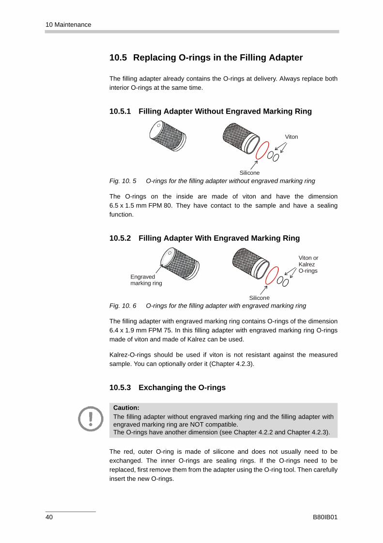
Fig. 10. 5 O-rings for the filling adapter without engraved marking ring
The O-rings on the inside are made of viton and have the dimension6.5 x 1.5 mm FPM 80. They have contact to the sample and have a sealingfunction.
10.5.2 Filling Adapter With Engraved Marking Ring
Fig. 10. 6 O-rings for the filling adapter with engraved marking ring
The filling adapter with engraved marking ring contains O-rings of the dimension6.4 x 1.9 mm FPM 75. In this filling adapter with engraved marking ring O-ringsmade of viton and made of Kalrez can be used.
Kalrez-O-rings should be used if viton is not resistant against the measuredsample. You can optionally order it (Chapter 4.2.3).
10.5.3 Exchanging the O-rings
The red, outer O-ring is made of silicone and does not usually need to beexchanged. The inner O-rings are sealing rings. If the O-rings need to bereplaced, first remove them from the adapter using the O-ring tool. Then carefullyinsert the new O-rings.
Silicone
Viton
Silicon
Viton or KalrezO-rings
Engravedmarking ring
e
Caution:The filling adapter without engraved marking ring and the filling adapter withengraved marking ring are NOT compatible. The O-rings have another dimension (see Chapter 4.2.2 and Chapter 4.2.3).
40 B80IB01
11 Technical DataTime measuring range: 0 - 250 s (999 s *)
Resolution: 0.001 secAccuracy: <0.002 sec
Viscosity range: 0.3 - 2500 mPa.s (20000 mPa.s *)Repeatability: <0.1 %**Reproducibility: <0.5 %***
Temperature range: +5 °C to +135 °CResolution: 0.01 °CAccuracy: <0.05 °C
Mains connection: 85 to 264 VAC, 50 to 60 Hz, 75 VA
Dimensions (W x H x D): 290 x 340 x 330 mm
Weight: 15 kg (150 N)
Ambient temperature: 15 to 35 °C
Air humidity: 10 to 80 % relative humidity for temperatures up to 31 °C, decreasing linearly to 67 % relative humidity at 35 °C
More detailed information about AMVn specifications are available on request.
*) with measuring range extension (see Chapter Appendix B:)
**) typical value, provided the ball is not changed
***) typical value for the range, where the calibration constant was determined
41 B80IB01
Appendix A: Viscosity
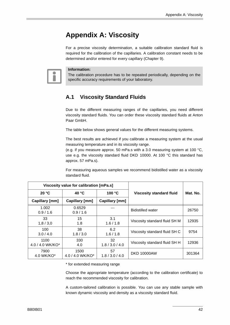
Appendix A: ViscosityFor a precise viscosity determination, a suitable calibration standard fluid isrequired for the calibration of the capillaries. A calibration constant needs to bedetermined and/or entered for every capillary (Chapter 9).
A.1 Viscosity Standard Fluids
Due to the different measuring ranges of the capillaries, you need differentviscosity standard fluids. You can order these viscosity standard fluids at AntonPaar GmbH.
The table below shows general values for the different measuring systems.
The best results are achieved if you calibrate a measuring system at the usualmeasuring temperature and in its viscosity range. (e.g. if you measure approx. 50 mPa.s with a 3.0 measuring system at 100 °C,use e.g. the viscosity standard fluid DKD 10000. At 100 °C this standard hasapprox. 57 mPa.s).
For measuring aqueous samples we recommend bidistilled water as a viscositystandard fluid.
* for extended measuring range
Choose the appropriate temperature (according to the calibration certificate) toreach the recommended viscosity for calibration.
A custom-tailored calibration is possible. You can use any stable sample withknown dynamic viscosity and density as a viscosity standard fluid.
Information:The calibration procedure has to be repeated periodically, depending on thespecific accuracy requirements of your laboratory.
Viscosity value for calibration [mPa.s]
Viscosity standard fluid Mat. No.20 °C 40 °C 100 °C
Capillary [mm] Capillary [mm] Capillary [mm]
1.0020.9 / 1.6
0.65290.9 / 1.6
--- Bidistilled water 26750
331,8 / 3,0
151.8
3.11.6 / 1.8 Viscosity standard fluid SH M 12935
1003.0 / 4.0
381.8 / 3.0
6.21.6 / 1.8 Viscosity standard fluid SH C 9754
11004.0 / 4.0 WK/KO*
3304.0
321.8 / 3.0 / 4.0 Viscosity standard fluid SH H 12936
79004.0 WK/KO*
15004.0 / 4.0 WK/KO*
571.8 / 3.0 / 4.0 DKD 10000AW 301364
B80IB01 42
Appendix A: Viscosity
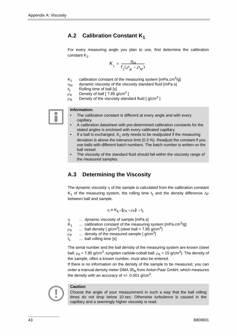
A.2 Calibration Constant K1
For every measuring angle you plan to use, first determine the calibrationconstant K1.
K1 calibration constant of the measuring system [mPa.cm3/g]ηN dynamic viscosity of the viscosity standard fluid [mPa.s]t1 Rolling time of ball [s]ρK Density of ball [ 7.85 g/cm3 ]ρN Density of the viscosity standard fluid [ g/cm3 ]
A.3 Determining the Viscosity
The dynamic viscosity η of the sample is calculated from the calibration constantK1 of the measuring system, the rolling time t1 and the density difference Δρbetween ball and sample.
η = K1 * (ρK - ρP) * t1
η ... dynamic viscosity of sample [mPa.s]K1 ... calibration constant of the measuring system [mPa.cm3/g]ρK ... ball density [ g/cm3] (steel ball = 7.85 g/cm3)ρP ... density of the measured sample [ g/cm3]t1 ... ball rolling time [s]
The serial number and the ball density of the measuring system are known (steelball: ρK = 7.85 g/cm3, tungsten carbide-cobalt ball: ρK = 15 g/cm3). The density ofthe sample, often a known number, must also be entered. If there is no information on the density of the sample to be measured, you canorder a manual density meter DMA 35N from Anton Paar GmbH, which measuresthe density with an accuracy of +/- 0.001 g/cm3.
K1
ηNt1ρ
K( ρN )–
-----------------------------------=
Information:• The calibration constant is different at every angle and with every
capillary.• A calibration datasheet with pre-determined calibration constants for the
stated angles is enclosed with every calibrated capillary.• If a ball is exchanged, K1 only needs to be readjusted if the measuring
deviation is above the tolerance limit (0.3 %). Readjust the constant if you use balls with different batch numbers. The batch number is written on the ball vessel.
• The viscosity of the standard fluid should fall within the viscosity range of the measured samples.
Caution:Choose the angle of your measurement in such a way that the ball rollingtimes do not drop below 10 sec. Otherwise turbulence is caused in thecapillary and a seemingly higher viscosity is read.
43 B80IB01
Appendix B: Extension of the Measuring Range
Appendix B: Extension of the Measuring Range
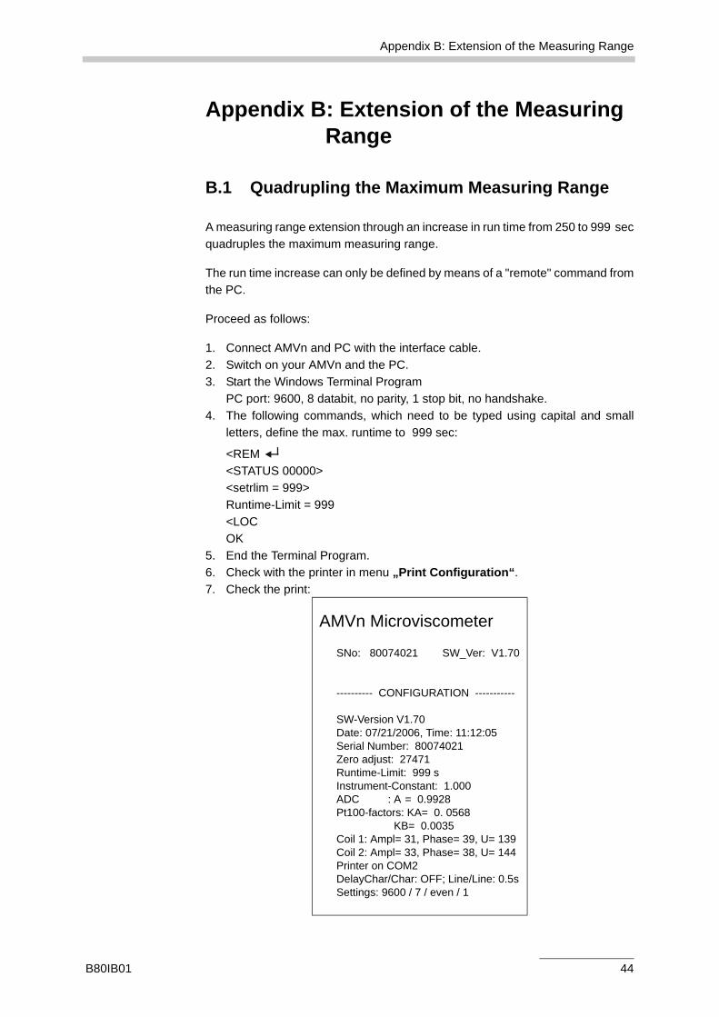
B.1 Quadrupling the Maximum Measuring Range
A measuring range extension through an increase in run time from 250 to 999 secquadruples the maximum measuring range.
The run time increase can only be defined by means of a "remote" command fromthe PC.
Proceed as follows:
1. Connect AMVn and PC with the interface cable. 2. Switch on your AMVn and the PC.3. Start the Windows Terminal Program
PC port: 9600, 8 databit, no parity, 1 stop bit, no handshake.4. The following commands, which need to be typed using capital and small
letters, define the max. runtime to 999 sec:
<REM <STATUS 00000><setrlim = 999>Runtime-Limit = 999<LOCOK
5. End the Terminal Program.6. Check with the printer in menu „Print Configuration“.7. Check the print:
AMVn Microviscometer
SNo: 80074021 SW_Ver: V1.70
---------- CONFIGURATION -----------
SW-Version V1.70Date: 07/21/2006, Time: 11:12:05Serial Number: 80074021Zero adjust: 27471Runtime-Limit: 999 sInstrument-Constant: 1.000ADC : A = 0.9928Pt100-factors: KA= 0. 0568
KB= 0.0035Coil 1: Ampl= 31, Phase= 39, U= 139Coil 2: Ampl= 33, Phase= 38, U= 144Printer on COM2DelayChar/Char: OFF; Line/Line: 0.5sSettings: 9600 / 7 / even / 1
B80IB01 44
Appendix B: Extension of the Measuring Range
B.2 Doubling the Maximum Measuring Range
A measuring range extension through the use of tungsten carbide-cobalt ballsdoubles the maximum measuring range, as they have approx. twice the density(15 g/cm³) and therefore half the runtime.
Before calibrating the measuring system 4.0 with tungsten carbide-cobalt balls,read Chapter 9 and proceed accordingly.
Proceed as follows:
1. Select capillary 4.0 mm.2. Insert 3 mm tungsten carbide-cobalt balls.3. Fill the capillary with viscosity standard fluid and start the calibration.
Save the calculated calibration constant for the measuring system 4.0.
45 B80IB01
Appendix C: Menu Tree – Firmware Structure
Appendix C: Menu Tree – Firmware Structure
S
tart
I
nitia
lizat
ion
actu
al S
ETTI
NG
S
Men
u
S
etup
Inst
rum
ent
D
ate
Sam
ple:
Nam
eR
emar
k
Tem
pera
ture
D
ensi
ty
M
etho
d:
N
ame
A
ngle
R
epet
ition
s
Cap
illar
y S
yst e
m
M
eas.
Sys
tem
:
Cap
illar
y S
er. N
o.
K1
C
alib
ratio
n D
ate
C
apill
ary
Sys
tem
In
str.
Set
tings
:
In
stru
men
t Con
stan
t K2
T
emp.
Equ
i-Mod
e
Ti
me
Zero
adj
ust
Tem
pera
ture
equ
ilibr
atio
n
S
etup
Tem
p. E
quil i
brat
ion
Inst
rum
ent C
ons t
ant K
2
D
efau
lt S
ettin
gs
C
onfig
urat
ion
Prin
ter
Info
Serv
ice
Util
ities
Softw
are
Upd
ate
F2 F
3
F1 F5
F1F1
F2
F1F5
F5
B80IB01 46
Appendix C: Menu Tree – Firmware Structure
Set
up M
easu
rem
ent
Met
hod
Set
up: M
easu
re-M
etho
d
F1F1
F5
F5
P
rint M
etho
ds
M
easu
ring
Sys
tem
Se
tup
Tem
p. E
quilib
ratio
n
Prin
t Mea
surin
g S
yste
ms
Mea
s. S
yste
m: C
alib
rate
Set
up: M
easu
re-M
easS
yste
m-C
alib
Prin
t Con
figur
atio
n
Eva
luat
ion
D
yn. V
isco
.:
Mea
n
Tim
e
St.D
ev.
Va
r. C
o.
Kin
. Vis
co.:
M
ean
Ti
me
St
.Dev
.
Var.
Co.
In
fos:
1/
2
Ang
le /
Met
hod
2/2
Star
t Tim
e
Rep
etiti
ons
Cap
illary
Ser
No.
Te
mpe
ratu
re
K1
D
ensi
ty
C
apill
ary
Sys
tem
R
epet
ition
Tim
es: d
iscr
ete
run
times
New
Run
Sam
ple
Nam
e
R
emar
k
Den
sity
Tem
pera
ture
T
emp.
Equ
i
Met
hod
M
easu
ring
Sys
tem
S
tart
RU
N -
Tem
p E
qui
RU
N
Stop
mea
sure
men
t
Sh
ow ru
ntim
es
F4F1
F5
F2 F
3F4 F1
F1F5
F5F1 F4
F2
F3
F1 F5
F2
F3F1
F1
F5F1
F2
47 B80IB01