Embed Size (px)
Citation preview

1
BARNSTEAD|THERMOLYNE CORPORATION
EASYpure™ LFOPERATION MANUAL
AND PARTS LISTSeries 1052
LT1052X2 • 9/8/97
2
IMPORTANT INFORMATIONThis manual contains important operating and safety information. You must carefully read and understand the contents of this manual prior to the use of this equipment.
Water purification technology employs one or more of the following: chemicals, electrical devices, mercuryvapor lamps, steam and heated vessels. Care should be taken when installing, operating or servicing
Barnstead products. The specific safety notes pertinent to this Barnstead product are listed on the followingpage.
Table of ContentsSafety Information ................................................................................................................................3
Alert Boxes ............................................................................................................................................3 Warnings ................................................................................................................................................4 Introduction ............................................................................................................................................5 Specifications ........................................................................................................................................6
Dimensions and Clearance Requirements. ......................................................................................6Feedwater Requirements ..................................................................................................................6 Product Water ....................................................................................................................................6 Electrical Requirements ....................................................................................................................6Environmental Conditions ..................................................................................................................6
Declaration of Conformity ......................................................................................................................7 Unpackaging and Installation ................................................................................................................8 Tubing Adapter Installation ....................................................................................................................9 Wall Mounting ......................................................................................................................................10 Initial Operation ....................................................................................................................................13
Cartridge Installation and Rinse Up ................................................................................................13 Normal Operation ................................................................................................................................14
Water Draw Off ................................................................................................................................14 Run and Standby Modes ................................................................................................................14
Installing Float or Pressure Switch ......................................................................................................15 Maintenance and Servicing..................................................................................................................16
Cartridge Replacement ....................................................................................................................16 Cartridge Removal ..................................................................................................................16
0.2 Micron Filter Replacement ........................................................................................................17 General Cleaning Instructions..........................................................................................................17 System Sanitization ........................................................................................................................17 Fuse Replacement ..........................................................................................................................18 Printed Circuit Board Replacement ................................................................................................19 Cleaning the Resistivity Cell ............................................................................................................21 Shutdown ........................................................................................................................................22 Troubleshooting ..............................................................................................................................23
Parts and Supplies ..............................................................................................................................25 Ordering Procedures ............................................................................................................................27 Flow Diagram ......................................................................................................................................28Wiring Diagram ....................................................................................................................................29Warranty ..............................................................................................................................................35
3
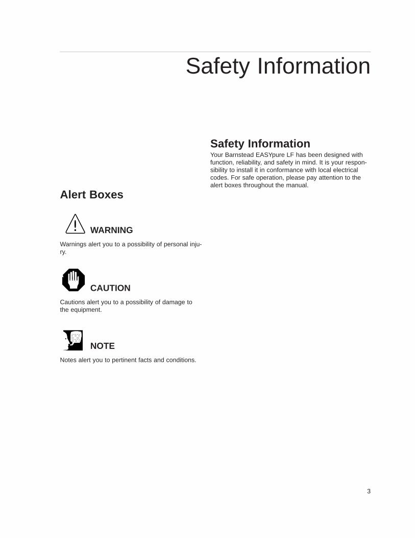
Safety InformationYour Barnstead EASYpure LF has been designed withfunction, reliability, and safety in mind. It is your respon-sibility to install it in conformance with local electricalcodes. For safe operation, please pay attention to thealert boxes throughout the manual.
Alert Boxes
WARNING
Warnings alert you to a possibility of personal inju-ry.
CAUTION
Cautions alert you to a possibility of damage tothe equipment.
NOTE
Notes alert you to pertinent facts and conditions.
Safety Information
4
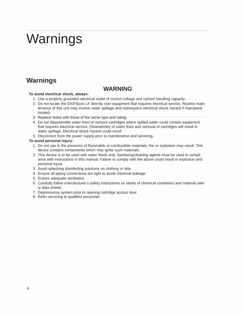
WarningsWARNING
To avoid electrical shock, always:1. Use a properly grounded electrical outlet of correct voltage and current handling capacity.2. Do not locate the EASYpure LF directly over equipment that requires electrical service. Routine main-
tenance of this unit may involve water spillage and subsequent electrical shock hazard if improperlylocated.
3. Replace fuses with those of the same type and rating.4. Do not disassemble water lines or remove cartridges where spilled water could contact equipment
that requires electrical service. Disassembly of water lines and removal of cartridges will result inwater spillage. Electrical shock hazard could result.
5. Disconnect from the power supply prior to maintenance and servicing.To avoid personal injury:
1. Do not use in the presence of flammable or combustible materials; fire or explosion may result. Thisdevice contains components which may ignite such materials.
2. This device is to be used with water feeds only. Sanitizing/cleaning agents must be used in compli-ance with instructions in this manual. Failure to comply with the above could result in explosion andpersonal injury.
3. Avoid splashing disinfecting solutions on clothing or skin.4. Ensure all piping connections are tight to avoid chemical leakage. 5. Ensure adequate ventilation.6. Carefully follow manufacturer’s safety instructions on labels of chemical containers and material safe-
ty data sheets.7. Depressurize system prior to opening cartridge access door.8. Refer servicing to qualified personnel.
Warnings
5
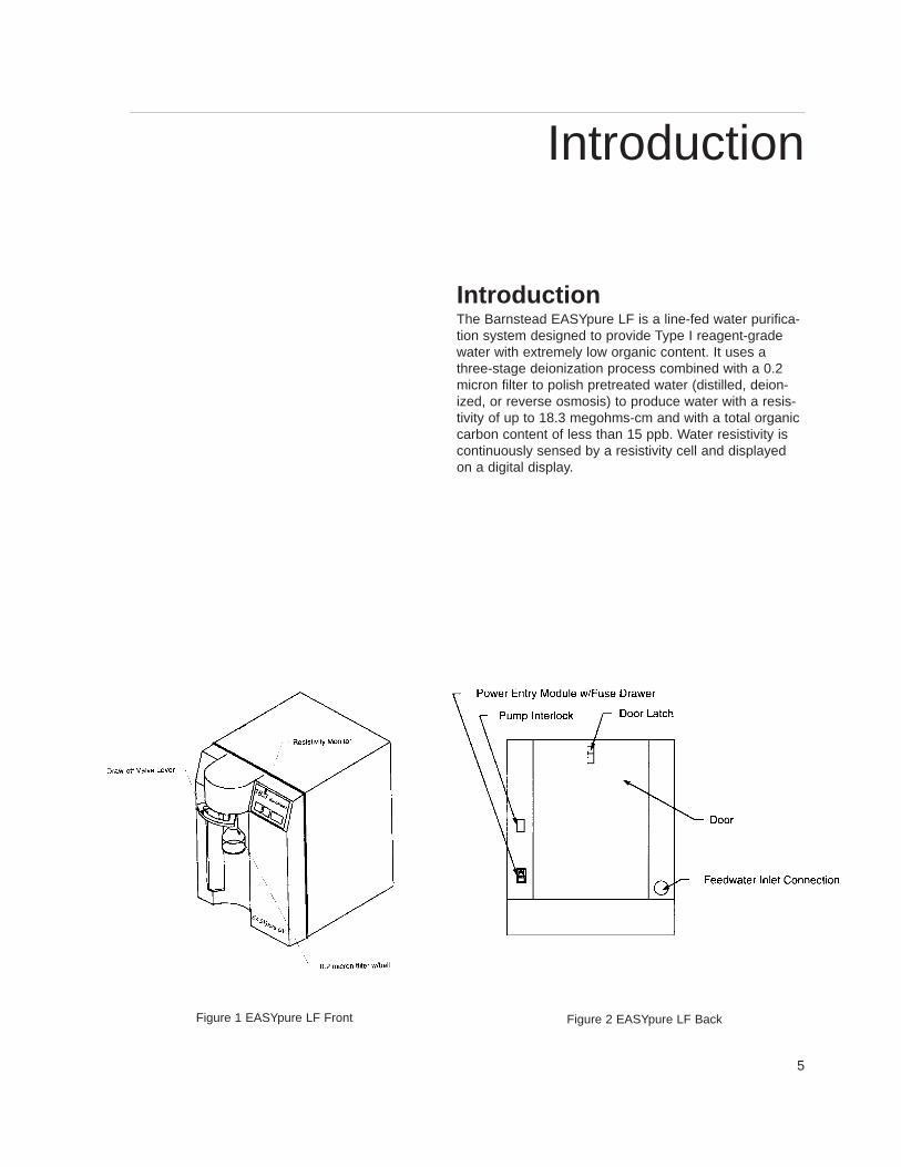
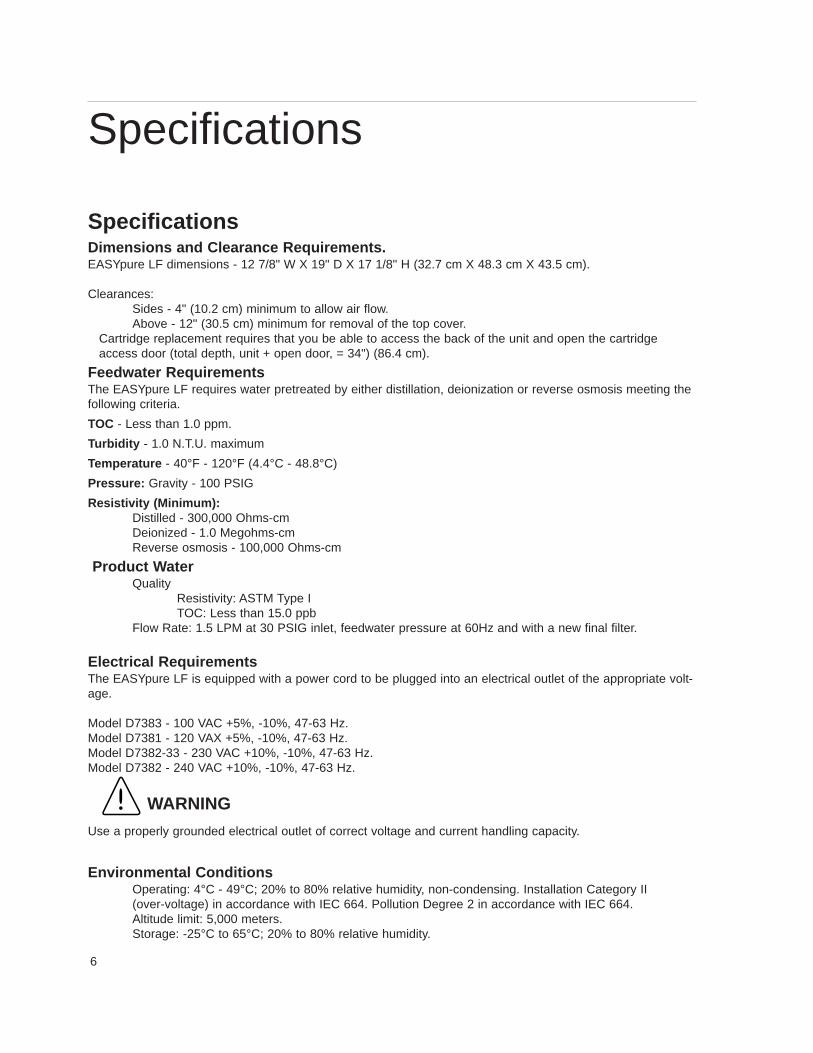
IntroductionThe Barnstead EASYpure LF is a line-fed water purifica-tion system designed to provide Type I reagent-gradewater with extremely low organic content. It uses athree-stage deionization process combined with a 0.2micron filter to polish pretreated water (distilled, deion-ized, or reverse osmosis) to produce water with a resis-tivity of up to 18.3 megohms-cm and with a total organiccarbon content of less than 15 ppb. Water resistivity iscontinuously sensed by a resistivity cell and displayedon a digital display.
Introduction
Figure 1 EASYpure LF Front Figure 2 EASYpure LF Back
6
SpecificationsDimensions and Clearance Requirements.EASYpure LF dimensions - 12 7/8" W X 19" D X 17 1/8" H (32.7 cm X 48.3 cm X 43.5 cm).
Clearances:Sides - 4" (10.2 cm) minimum to allow air flow.Above - 12" (30.5 cm) minimum for removal of the top cover.
Cartridge replacement requires that you be able to access the back of the unit and open the cartridgeaccess door (total depth, unit + open door, = 34") (86.4 cm).
Feedwater RequirementsThe EASYpure LF requires water pretreated by either distillation, deionization or reverse osmosis meeting thefollowing criteria.
TOC - Less than 1.0 ppm.
Turbidity - 1.0 N.T.U. maximum
Temperature - 40°F - 120°F (4.4°C - 48.8°C)
Pressure: Gravity - 100 PSIG
Resistivity (Minimum):Distilled - 300,000 Ohms-cmDeionized - 1.0 Megohms-cmReverse osmosis - 100,000 Ohms-cm
Product W ater Quality
Resistivity: ASTM Type ITOC: Less than 15.0 ppb
Flow Rate: 1.5 LPM at 30 PSIG inlet, feedwater pressure at 60Hz and with a new final filter.
Electrical RequirementsThe EASYpure LF is equipped with a power cord to be plugged into an electrical outlet of the appropriate volt-age.
Model D7383 - 100 VAC +5%, -10%, 47-63 Hz.Model D7381 - 120 VAX +5%, -10%, 47-63 Hz.Model D7382-33 - 230 VAC +10%, -10%, 47-63 Hz.Model D7382 - 240 VAC +10%, -10%, 47-63 Hz.
WARNING
Use a properly grounded electrical outlet of correct voltage and current handling capacity.
Environmental Conditions Operating: 4°C - 49°C; 20% to 80% relative humidity, non-condensing. Installation Category II (over-voltage) in accordance with IEC 664. Pollution Degree 2 in accordance with IEC 664. Altitude limit: 5,000 meters.Storage: -25°C to 65°C; 20% to 80% relative humidity.
Specifications
7
Declaration of ConformityBarnstead|Thermolyne hereby declares under its sole re-sponsibility that this product conforms with the technicalrequirements of the following standards:
EMC: EN 50081-1 Generic Emission Standard;EN 50082-1 Generic Immunity Standard;
Safety: IEC 1010-1-92 Safety requirements forelectrical equipment for measurement, control, and laboratory use; Part I: General Requirementsper the provisions of the Electromagnetic CompatabilityDirective 89/336/EEC, as amended by 92/31/EEC and93/68/EEC, and per the provisions of the Low VoltageDirective 73/23/EEC, as amended by 93/68/EEC.
The authorized representative located within the Europe-an Community is:
European ManagerBarnstead|ThermolyneSaarbrückener Str. 248D-38116 BraunschweigGermany
Copies of the Declaration of Conformity are availableupon request.
8
Unpackaging and Installation1. Remove the unit from its shipping container. Ensure
that the tubing, adapter and power cord are removedfrom the packaging materials before discarding.
Description Catalog NumberEASYpure High Purity/Low TOC Cartridge D50229 Pretreatment Cartridge DI Feed D50230Pretreatment Cartridge R/O - Distilled Feed D50231 Ultrapure Mixed Bed Cartridge D50233Filter, 0.2 Micron FL703X2
2. Place the EASYpure LF on a bench top convenient toyour work area, noting the Clearance Requirements.
3. Tape the 1/4" OD x 1/4" NPT tubing adapter using 11/2 to 2 turns of Teflon® tape, and install it on your in-coming water line or your storage reservoir.
4. Install one end of the tubing to this adapter, but do notinstall the other end on the EASYpure LF until car-tridges have been installed. You will connect thewater supply to the quick disconnect body in the InitialOperation section. Refer to the Tubing Adapter In -stallation section of this manual.
NOTE
Cartridges and the 0.2 micron final filter are notprovided with the EASYpure LF and must be or-dered separately.
WARNING
Do not locate the EASYpure LF directly overequipment that requires electrical service.Routine maintenance of this unit may involvewater spillage and subsequent electrical shockhazard if improperly located.
Do not use in the presence of flammable orcombustible materials; fire or explosion mayresult. This device contains components whichmay ignite such materials.
This device is to be used with water feeds only.Sanitizing/cleaning agents must be used incompliance with instructions in this manual.Failure to comply with the above could result inexplosion and personal injury.
NOTE
If you purchased a wall mount bracket for theEASYpure LF, refer to the Wall Mounting sec-tion of this manual.
NOTE
The outlet of your storage reservoir must belevel with the inlet of the EASYpure LF.
NOTE
To disrupt the flow of water to the EASYpure LF,press the stainless steel thumb pad on thequick disconnect fitting. The insert with thevalve is easily removed. To resupply theEASYpure LF with water, push the insert intothe coupling body and listen for the click thatindicates full closure.
Unpackaging and Installation
9
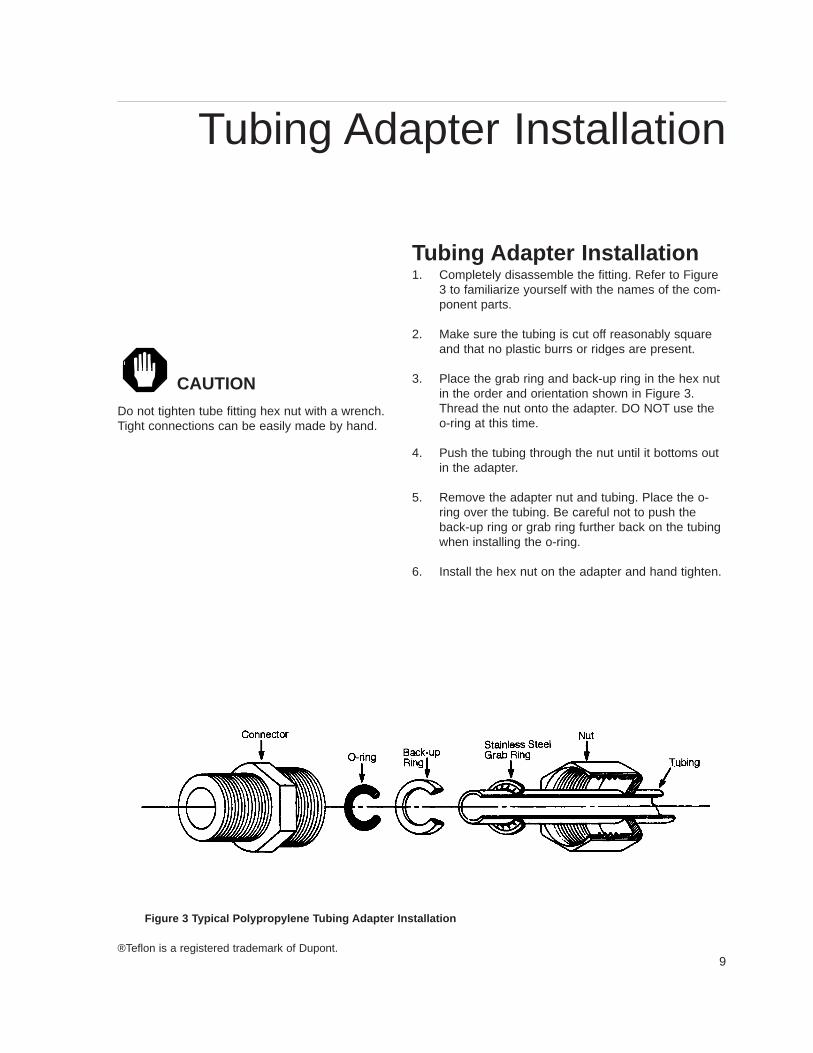
Tubing Adapter Installation1. Completely disassemble the fitting. Refer to Figure
3 to familiarize yourself with the names of the com-ponent parts.
2. Make sure the tubing is cut off reasonably squareand that no plastic burrs or ridges are present.
3. Place the grab ring and back-up ring in the hex nutin the order and orientation shown in Figure 3.Thread the nut onto the adapter. DO NOT use theo-ring at this time.
4. Push the tubing through the nut until it bottoms outin the adapter.
5. Remove the adapter nut and tubing. Place the o-ring over the tubing. Be careful not to push theback-up ring or grab ring further back on the tubingwhen installing the o-ring.
6. Install the hex nut on the adapter and hand tighten.
Figure 3 T ypical Polypropylene T ubing Adapter Installation
®Teflon is a registered trademark of Dupont.
CAUTION
Do not tighten tube fitting hex nut with a wrench.Tight connections can be easily made by hand.
Tubing Adapter Installation
10
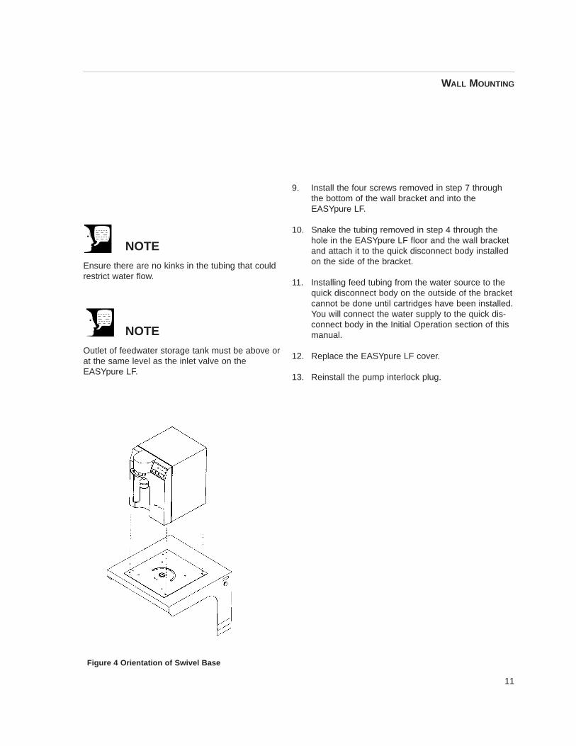
Wall MountingInstall the wall bracket on the wall in a location that is ac-cessible to water and convenient to use. A minimum of 4fasteners must be used.
1. Remove the pump interlock plug from the rear of theunit.
2. Open cartridge access door in the rear of the unit.
3. Remove the cover of the EASYpure LF by removingthe screws that secure it to the unit and lifting itstraight up.
4. Remove tubing attached to quick disconnect body.
5. Remove the inlet quick disconnect body from the rearof the EASYpure LF cabinet.
6. On both sides of the wall bracket there are plugs. Re-move the plug from the side that is most accessible toyour feedwater source. Install the inlet quick discon-nect body fitting into the hole by placing the inlet quickdisconnect into the hole and secure in place with thelocknut inside. Replace the plug in the hole generatedin the EASYpure LF (where the disconnect body wasinstalled).
7. Remove the four feet from the EASYpure LF andretain the screws.
8. Place the EASYpure LF on the wall bracket swivelbase so the screw holes where the feet were attachedline up with the holes in the wall bracket. There areguides on the wall bracket that will mate with theEASYpure LF.
WARNING
Do not locate the EASYpure LF directly overequipment that requires electrical service. Rou-tine maintenance of this unit may involve waterspillage and subsequent electrical shock hazardif improperly located.
CAUTION
Wall composition, condition and construction, aswell as fastener type, must be considered whenmounting this unit. The mounting surface andfasteners selected must be capable of support-ing a minimum of 150 lbs. Inadequate supportand/or fasteners may result in damage tomounting surface and/or equipment. If you areunsure of mounting surface composition, condi-tion and construction or correct fasteners, con-sult your building maintenance group or con-tractor.
Wall Mounting
11
9. Install the four screws removed in step 7 throughthe bottom of the wall bracket and into theEASYpure LF.
10. Snake the tubing removed in step 4 through thehole in the EASYpure LF floor and the wall bracketand attach it to the quick disconnect body installedon the side of the bracket.
11. Installing feed tubing from the water source to thequick disconnect body on the outside of the bracketcannot be done until cartridges have been installed.You will connect the water supply to the quick dis-connect body in the Initial Operation section of thismanual.
12. Replace the EASYpure LF cover.
13. Reinstall the pump interlock plug.
Figure 4 Orientation of Swivel Base
NOTE
Ensure there are no kinks in the tubing that couldrestrict water flow.
NOTE
Outlet of feedwater storage tank must be above orat the same level as the inlet valve on theEASYpure LF.
WALL MOUNTING
12
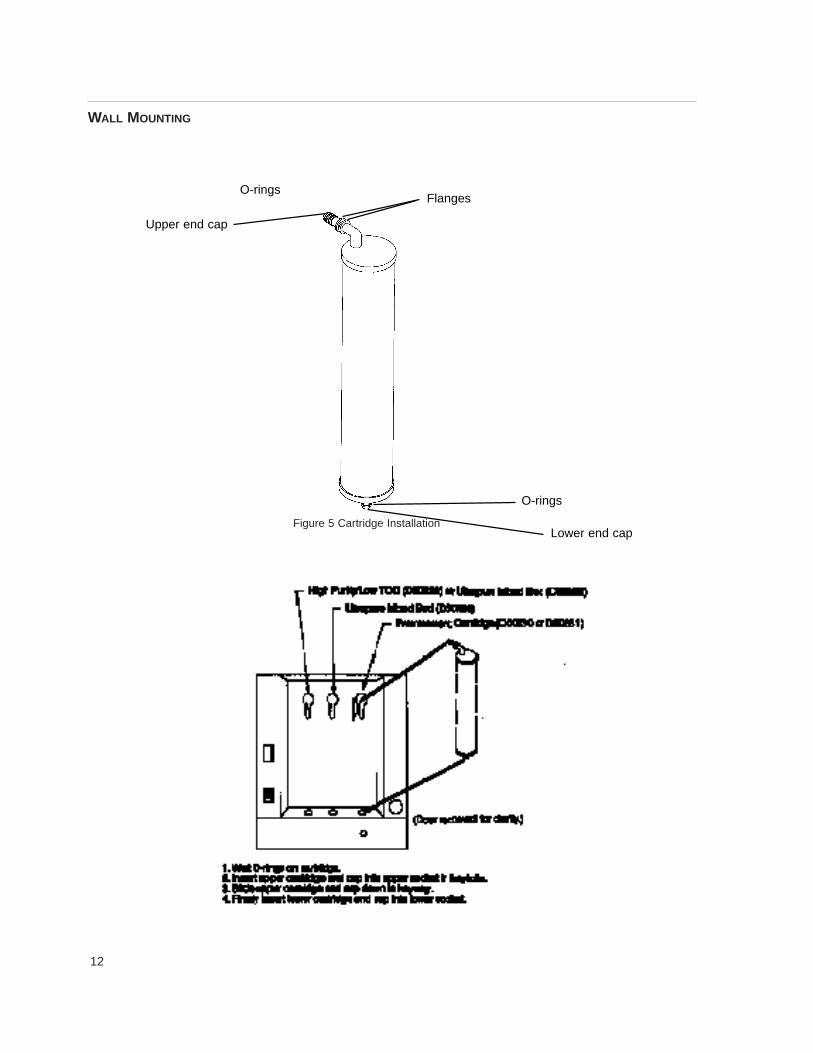
Figure 5 Cartridge Installation
WALL MOUNTING
O-rings
Upper end cap
Flanges
O-rings
Lower end cap
13
Initial OperationCartridge Installation and Rinse Up
1. Open cartridge access door in the rear of the unitby pushing the door latch down.
2. Remove a new Pretreatment cartridge (Catalog No.D50230 or D50231) from its plastic bag.
3. Wet the o-rings on both end caps.
4. Press the upper end cap into the upper right posi-tion until it bottoms out.
5. Lower the cartridge and insert the lower end capinto the lower socket until it is firmly seated.
6. Repeat steps 2 - 5 with the EASYpure ULTRApureand High Purity/Low TOC cartridges, placing themin the center and left-hand positions. Do not install0.2 micron filter and bell assembly at this time.
7. Close cartridge access door.
8. Open draw-off valve.
9. Connect water supply to quick disconnect body.
10. Plug power cord into the unit’s power entry moduleand plug into a live outlet. Turn on power entrymodule switch.
11. Press “START”.
12. Rinse 5-10 liters of water through the cartridges todrain.
13. Remove a new 0.2 micron filter and bell assemblyfrom its bag and insert it into the Luer fitting. Gentlyturn it clockwise until it is fully seated in the Luer fit-ting.
14. Remove the protective cap from the filter bell.
15. Flush 5-10 liters of water through the filter to waste.
NOTE
If the EASYpure LF is wall mounted, rotate theEASYpure LF until the cartridge access door facesforward and the EASYpure LF locks into place.
NOTE
The EASYpure LF’s cartridges must be installedin the proper order.
NOTE
The upper end cap is the one with the right-angleturn and the two flanges. The lower end cap ex-tends straight out from the cartridge.
NOTE
The two flanges on the end cap should be able toslide down on each side of the keyway wall.
WARNING
Use a properly grounded electrical outlet of correctvoltage and current handling capacity.
CAUTION
Do not allow EASYpure LF to operate unlesswater is available to unit.
NOTE
For more demanding applications where low TOCwater is required, a rinse of 15-20 liters throughthe cartridges and filter may be necessary.
Initial Operation
14
Normal Operation1. Press the “START” button on the front of the
EASYpure LF.
The EASYpure LF’s pump will begin to run and the Puritymeter will display the resistivity of the water in megohm-cm.
2. Allow the water’s resistivity to rise to the desired puritybefore drawing off water.
Water Draw Off1. Remove the protective cap from the filter bell.
2. Depress the draw-off lever.
3. When draw off is complete, lift the draw-off lever andreplace the protective cap on the filter bell.
Run and Standby ModesSince not all qualities of permissible feedwater will reachmaximum resistivity after one pass through the unit’s car-tridges (especially as the cartridges near exhaustion), theEASYpure LF has two operational modes.
In the run mode, the pump continuously recirculates waterthrough the cartridges. This is the mode that the unit entersupon startup. If water will be drawn from the EASYpure LFon a continuous basis throughout the day, it is recommend-ed that the EASYpure LF be left in the run mode. In the runmode, the purity meter display indicates the resistivity ofthe water available for draw off.
In standby mode, the pump runs for ten minutes out of ev-ery hour (i.e. ten minutes on, fifty minutes off). If water willbe drawn from the unit only infrequently, it is recommendedthat the unit be put into standby mode. To put the unit intostandby mode, press the “STANDBY” button on the front ofthe unit. The purity meter’s digital display will display “Sby”to indicate that the unit is in standby mode.
NOTE
On initial startup, the purity meter may display“ERR.” This is caused by air in the cell andshould be replaced by a resistivity reading al-most immediately. If “ERR” does not go outafter the pump has run for a minute or if itappears any time while the EASYpure LF is inoperation, refer to the Troubleshooting sectionof this manual.
NOTE
For low organic applications, draw off 50 to 100ml of water from system and discard prior todrawing water for use.
Normal Operation
15
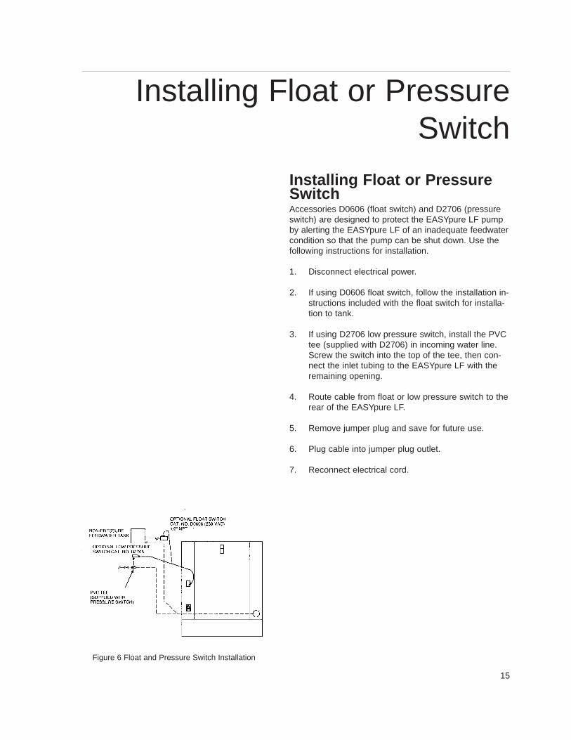
Installing Float or PressureSwitchAccessories D0606 (float switch) and D2706 (pressureswitch) are designed to protect the EASYpure LF pumpby alerting the EASYpure LF of an inadequate feedwatercondition so that the pump can be shut down. Use thefollowing instructions for installation.
1. Disconnect electrical power.
2. If using D0606 float switch, follow the installation in-structions included with the float switch for installa-tion to tank.
3. If using D2706 low pressure switch, install the PVCtee (supplied with D2706) in incoming water line.Screw the switch into the top of the tee, then con-nect the inlet tubing to the EASYpure LF with theremaining opening.
4. Route cable from float or low pressure switch to therear of the EASYpure LF.
5. Remove jumper plug and save for future use.
6. Plug cable into jumper plug outlet.
7. Reconnect electrical cord.
Installing Float or PressureSwitch
Figure 6 Float and Pressure Switch Installation
16
Maintenance and Servicing
Cartridge Replacement The frequency with which you will need to replace cartridg-es is dependent on your feedwater’s characteristics, yourpurity requirements and your usage. Replace the cartridgeswhen the product water purity drops below acceptable lev-els of resistivity or when organic levels become too high.
Cartridge Removal1. Turn unit off.
2. Disconnect the unit from the power supply.
3. Disconnect incoming water line at quick disconnect.Depressurize system by opening outlet valve.
4. Open the cartridge access door in the rear of the unitby sliding the latch down and pulling the door towardyou. The door will swing down.
5. Grasp one of the cartridges at the bottom and pull itstraight up to disconnect the lower end cap from thelower socket.
6. Move cartridge upward until upper socket is in keyholeof keyway.
7. Pull cartridge straight out from unit to disconnectupper end cap from upper socket.
8. Repeat steps for the other cartridges.
9. Discard the used cartridges. (See note below.)
10. Install new cartridges and rinse according to the in-structions for Cartridge Installation in the Initial Op -eration section.
WARNING
Disconnect from the power supply prior tomaintenance and servicing.
Refer servicing to qualified personnel.
Do not disassemble water lines or remove car-tridges where spilled water could contact equip-ment that requires electrical service. Disassem-bly of water lines and removal of cartridges willresult in water spillage. Electrical shock hazardcould result.
NOTE
The cartridges will still contain water when re-moved. Therefore, you will want to have a sink,bucket or other waterproof container availableto place them in after removal.
WARNING
Depressurize system prior to opening cartridgeaccess door.
NOTE
If the EASYpure LF is wall mounted, removethe power cord and rotate the EASYpure LFuntil the cartridge access door faces forwardand the EASYpure LF locks into place.
NOTE
A small amount of water will drain from the car-tridge when it is disconnected from the lowersocket. Plug the cartridge’s lower opening withyour finger to minimize water spillage while youfinish removing the cartridge.
Maintenance and Servicing
17
0.2 Micron Filter ReplacementReplace the 0.2 micron filter whenever any of the follow-ing conditions occur: every 30 days, theproduct water flow rate is reduced or bacteria breakthrough. The 0.2 micron filter is shipped assembled witha bell. To replace the 0.2 micron filter assembly:1. Remove the old 0.2 micron filter assembly by turn-
ing it counter-clockwise until it is free from the Luerfitting.
2. Remove the new 0.2 micron filter assembly from itsbag and insert it into the Luer fitting. Gently turn itclockwise until it is fully seated in the Luer fitting.
3. Rinse at least 10 liters of water through the filter todrain prior to using the product water.
General Cleaning InstructionsWipe exterior surfaces with lightly dampened cloth con-taining mild soap solution.
System Sanitization The frequency with which you will need to clean yourunit and replace your cartridges is dependent on yourfeedwater’s characteristics, your purity requirements andyour usage. Sanitize your EASYpure LF and replace thecartridges when the product water purity drops below ac-ceptable levels of resistivity, when organic levelsbecome too high, or if a new 0.2 micron filter clogsrapidly after installation even though the cartridges werethoroughly rinsed before the 0.2 micron filter wasinstalled. To sanitize the EASYpure LF, the purificationcartridges must be replaced with a sanitization cartridgeand the two empty cartridges. The simple-to-use saniti-zation cartridge (Catalog Number D50245) and twoempty cartridges (D7034) are available fromBarnstead|Thermolyne or your local representative.
1. Turn the unit off.
2. Disconnect the unit from the power supply. Discon-nect the unit from the water supply.
NOTE
Used cartridges may be recycled. See P.U.R.E. in-formation packed with new cartridges.
CAUTION
Do not overtighten the 0.2 micron filter assemblyonto the Luer fitting or use excessive force in seat-ing it. The filter and/or Luer fitting can be damagedby overtightening or excessive force.
NOTE
If a newly installed 0.2 micron filter clogs rapidlyafter installation, the EASYpure LF may need tobe sanitized to remove bacterial contaminants.See System Sanitization .
WARNING
Disconnect from the power supply prior to main-tenance and servicing. Refer servicing to quali-fied personnel.
Avoid splashing disinfecting solutions on clothingor skin.
Ensure all piping connections are tight to avoidchemical leakage.
Ensure adequate ventilation.
Carefully follow manufacturer’s safety instructionson labels of chemical containers and materialsafety data sheets.
NOTE
The cartridges will still contain water when re-moved. Therefore, you will want to have a sink,bucket or other waterproof container available toplace them in after removal.
MAINTENANCE AND SERVICING
18
3. Depressurize system by opening the draw-offvalve.
4. Open the cartridge access door in the rear of the unitby sliding the latch down and pulling the door towardyou. The door will swing down.
5. Remove exhausted cartridge in the right-hand positionby pulling it first up and then out.
6. Remove a D50245 sanitization cartridge from its pack-aging. Press the upper end cap of the D50245 saniti-zation cartridge into the upper right position until it bot-toms out.
7. Lower the cartridge and insert the lower end cap intothe lower socket until it is firmly seated.
8. Repeat steps 2 - 6 with the two empty cartridges sup-plied with your EASYpure LF, placing them in the cen-ter and left-hand positions.
9. Close the cartridge access door. Remove the 0.2 mi-cron filter and bell assembly.
10. Sanitize, install new cartridges and rinse according tothe instructions for Cartridge Installation and Rinse Upin the Initial Operation section.
Fuse Replacement1. Turn the system off.
2. Disconnect incoming water line at quick disconnect.Depressurize system by opening outlet valve.
3. Disconnect the EASYpure LF from the power supply.
4. Remove the power cord from the power entry module,and remove the pump interlock plug from the rear ofthe unit.
5. Remove the screws securing the EASYpure LF cover.
6. Remove the cover by lifting it straight up.
7. Pull out the fuse drawer located in the power entrymodule.
WARNING
Depressurize system prior to opening cartridgeaccess door.
NOTE
If the EASYpure LF is wall mounted, removethe power cord and rotate the EASYpure LFuntil the cartridge access door faces forwardand the EASYpure LF locks into place.
NOTE
The two flanges on the end cap should be ableto slide down on each side of the keyway wall.
WARNING
Depressurize system prior to opening cartridgeaccess door.
MAINTENANCE AND SERVICING
19
8. Replace fuse drawer.
9. Replace cover, power cord, and pump interlockplug.
10. Reconnect unit to power supply, and connect in-coming water line at quick disconnect.
Printed Circuit Board Replacement1. Turn system off.
2. Disconnect incoming water line at quick disconnect.Depressurize system by opening outlet valve.
3. Disconnect the EASYpure LF from the power sup-ply.
4. Remove the power cord from the power entry mod-ule, and remove the pump interlock plug from therear of the unit.
5. Remove the screws securing the EASYpure LF cov-er.
6. Remove the cover by lifting it straight up.
7. Remove the filter and the Luer fitting.
8. Remove the screws securing the front cover. Re-move the front cover.
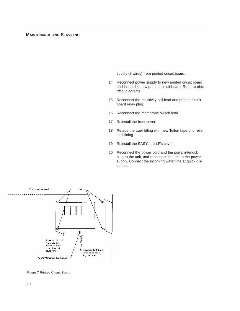
9. Disconnect the membrane switch lead from theprinted circuit board.
10. Disconnect the resistivity cell lead from the printedcircuit board.
11. Disconnect the printed circuit board relay plug bysqueezing the retaining clip while pulling the plugstraight out from the frame.
12. Remove the nuts holding the printed circuit board inplace.
13. Remove the printed circuit board. Disconnect power
WARNING
Replace fuses with those of the same type andrating. (See Parts Listing)
WARNING
Depressurize system prior to opening cartridge ac-cess door.
MAINTENANCE AND SERVICING
20
supply (3 wires) from printed circuit board.
14. Reconnect power supply to new printed circuit boardand install the new printed circuit board. Refer to elec-trical diagrams.
15. Reconnect the resistivity cell lead and printed circuitboard relay plug.
16. Reconnect the membrane switch lead.
17. Reinstall the front cover.
18. Retape the Luer fitting with new Teflon tape and rein-stall fitting.
19. Reinstall the EASYpure LF’s cover.
20. Reconnect the power cord and the pump interlockplug to the unit, and reconnect the unit to the powersupply. Connect the incoming water line at quick dis-connect.
MAINTENANCE AND SERVICING
Figure 7 Printed Circuit Board
21
Cleaning the Resistivity Cell1. Turn unit off.
2. Disconnect incoming water line at quick disconnect.Depressurize system by opening outlet valve.
3. Disconnect the EASYpure LF from the power sup-ply.
4. Remove the power cord from the power entry mod-ule, and remove the pump interlock plug from therear of the unit.
5. Remove the screws securing the EASYpure LF cov-er.
6. Remove the cover by lifting it straight up. Removethe filter and Luer fitting. Carefully remove the frontcover. Disconnect membrane switch lead from theprinted circuit board.
7. Remove the screw holding the cell-cable retainingclip.
8. Disconnect the cell lead from the printed circuitboard and gently pull the cable out of the EASYpureLF frame.
9. Unscrew and remove the cell.
10. Carefully remove the O-ring before cleaning thecell.
11. Wash the cell in a mild detergent solution or a 10%Hydrochloric or Sulfuric acid solution (follow acidmanufacturers warnings and recommended han-dling procedure). This may be done in an ultrasoniccleaner or with a soft brush.
12. Thoroughly rinse the cell in deionized or distilledwater following the detergent or acid cleaning.
13. After cleaning, reinstall and check the o-ring on cell;replace if necessary.
WARNING
Depressurize system prior to opening cartridge ac-cess door.
CAUTION
The cell electrodes are etched to improve wettingcharacteristics. Do not mechanically abrade ordamage this surface (i.e. do not clean with a wirebrush, sandpaper, etc.).
WARNING
Carefully follow manufacturer’s safety instructionson labels of chemical containers and materialsafety data sheets.
CAUTION
Do not immerse the entire cell assembly in clean-ing solution, only the electrode portion.
MAINTENANCE AND SERVICING

22
14. Reinstall the cell into the cell well and hand tighten.Reroute the cable up through the housing and recon-nect.
15. Reinstall the screw holding the cell-cable retainingclip. Reinstall membrane switch lead. Replace thefront cover. Retape the Luer fitting with new Teflontape and reinstall fitting. Replace the top cover.
16. Reconnect the power cord and the pump interlockplug to the unit, and reconnect the unit to the powersupply. Connect incoming water line at quick discon-nect.
ShutdownIf the EASYpure LF is to be shut down for an extended pe-riod of time, the unit should be completely drained and thecartridges removed to prevent the growth of bacteria.
If the system has remained inactive and full of water formore than 96 hours, the unit should be drained, sanitizedand new cartridges installed prior to use.
MAINTENANCE AND SERVICING
23
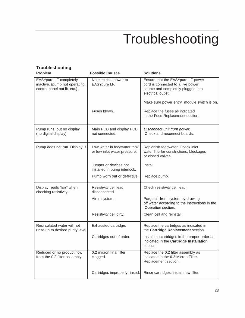
TroubleshootingProblem Possible Causes Solutions
EASYpure LF completely No electrical power to Ensure that the EASYpure LF power inactive. (pump not operating, EASYpure LF. cord is connected to a live powercontrol panel not lit, etc.). source and completely plugged into
electrical outlet.
Make sure power entry module switch is on.
Fuses blown. Replace the fuses as indicated in the Fuse Replacement section.
Pump runs, but no display Main PCB and display PCB Disconnect unit from power.(no digital display). not connected. Check and reconnect boards.
Pump does not run. Display lit. Low water in feedwater tank Replenish feedwater. Check inlet or low inlet water pressure. water line for constrictions, blockages
or closed valves.
Jumper or devices not Install.installed in pump interlock.
Pump worn out or defective. Replace pump.
Display reads “Err” when Resistivity cell lead Check resistivity cell lead.checking resistivity. disconnected.
Air in system. Purge air from system by drawingoff water according to the instructions in theOperation section.
Resistivity cell dirty. Clean cell and reinstall.
Recirculated water will not Exhausted cartridge. Replace the cartridges as indicated inrinse up to desired purity level. the Cartridge Replacement section.
Cartridges out of order. Install the cartridges in the proper order as indicated In the Cartridge Installationsection.
Reduced or no product flow 0.2 micron final filter Replace the 0.2 filter assembly as from the 0.2 filter assembly. clogged. indicated in the 0.2 Micron Filter
Replacement section.
Cartridges improperly rinsed. Rinse cartridges; install new filter.
Troubleshooting

24
Problem Possible Causes Solutions
0.2 micron final filter clogs EASYpure LF contaminated Sanitize EASYpure LF according rapidly after replacement. with bacteria. to the instructions in System
Sanitization . Replace the 0.2 filter assembly as indicated in the 0.2Micron Filter Replacement section.
Short cartridge life. Cartridges being used are beyond Check the expiration date. Cartridgesexpiration date begin to lose capacity after being
stored two years from the date of manufacture. Replace the cartridgeswith unexpired ones.
Change in feedwater characteristics. If a Barnstead ROpure is the feedwater source, check that the membrane is functioning properly.
If a Barnstead Still is the feedwater source, ensure that the distillatetemperature does not exceed 120°F when added to the EASYpure LF feedwater reservoir.
If feedwater is from a central water purification system, verify waterquality and proper functioning of the system.
Water leakage inside Cartridge connecting tubing not Press connecting tubing firmly intoEASYpure LF. fully seated into sockets. sockets.
Missing or defective cartridge Install or replace cartridge O-rings. O-rings.
TROUBLESHOOTING
25
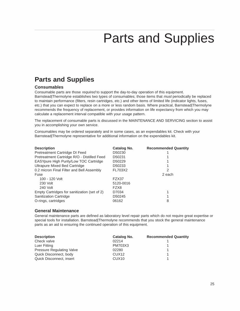
Parts and SuppliesConsumablesConsumable parts are those required to support the day-to-day operation of this equipment. Barnstead|Thermolyne establishes two types of consumables; those items that must periodically be replacedto maintain performance (filters, resin cartridges, etc.) and other items of limited life (indicator lights, fuses,etc.) that you can expect to replace on a more or less random basis. Where practical, Barnstead|Thermolynerecommends the frequency of replacement, or provides information on life expectancy from which you maycalculate a replacement interval compatible with your usage pattern.
The replacement of consumable parts is discussed in the MAINTENANCE AND SERVICING section to assistyou in accomplishing your own service.
Consumables may be ordered separately and in some cases, as an expendables kit. Check with yourBarnstead|Thermolyne representative for additional information on the expendables kit.
Description Catalog No. Recommended QuantityPretreatment Cartridge DI Feed D50230 1Pretreatment Cartridge R/O - Distilled Feed D50231 1EASYpure High Purity/Low TOC Cartridge D50229 1Ultrapure Mixed Bed Cartridge D50233 10.2 micron Final Filter and Bell Assembly FL703X2 2Fuse 2 each
100 - 120 Volt FZX37 230 Volt 5120-0016240 Volt FZX8
Empty Cartridges for sanitization (set of 2) D7034 1Sanitization Cartridge D50245 1O-rings, cartridges 06162 8
General MaintenanceGeneral maintenance parts are defined as laboratory level repair parts which do not require great expertise orspecial tools for installation. Barnstead|Thermolyne recommends that you stock the general maintenanceparts as an aid to ensuring the continued operation of this equipment.
Description Catalog No. Recommended QuantityCheck valve 02214 1Luer Fitting PM703X3 1Pressure Regulating Valve 02280 1Quick Disconnect, body CUX12 1Quick Disconnect, insert CUX10 1
Parts and Supplies
26
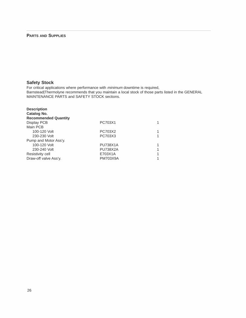
Safety StockFor critical applications where performance with minimum downtime is required, Barnstead|Thermolyne recommends that you maintain a local stock of those parts listed in the GENERALMAINTENANCE PARTS and SAFETY STOCK sections.
DescriptionCatalog No.Recommended QuantityDisplay PCB PC703X1 1Main PCB
100-120 Volt PC703X2 1230-230 Volt PC703X3 1
Pump and Motor Ass’y.100-120 Volt PU738X1A 1230-240 Volt PU738X2A 1
Resistivity cell E703X1A 1Draw-off valve Ass’y. PM703X9A 1
PARTS AND SUPPLIES
27
Ordering ProceduresPlease refer to the Specification Plate for the completemodel number, serial number, and series number whenrequesting service, replacement parts or in any corre-spondence concerning this unit.
All parts listed herein may be ordered from theBarnstead|Thermolyne dealer from whom you pur-chased this unit or can be obtained promptly from thefactory. When service or replacement parts are neededwe ask that you check first with your dealer. If the dealercannot handle your request, then contact our CustomerService Department at 319-556-2241 or 800-553-0039.
Prior to returning any materials toBarnstead|Thermolyne Corp ., please contact our Cus-tomer Service Department for a “Return Goods Authori-zation” number (RGA). Material returned without a RGAnumber will be refused.
Ordering Procedures
28
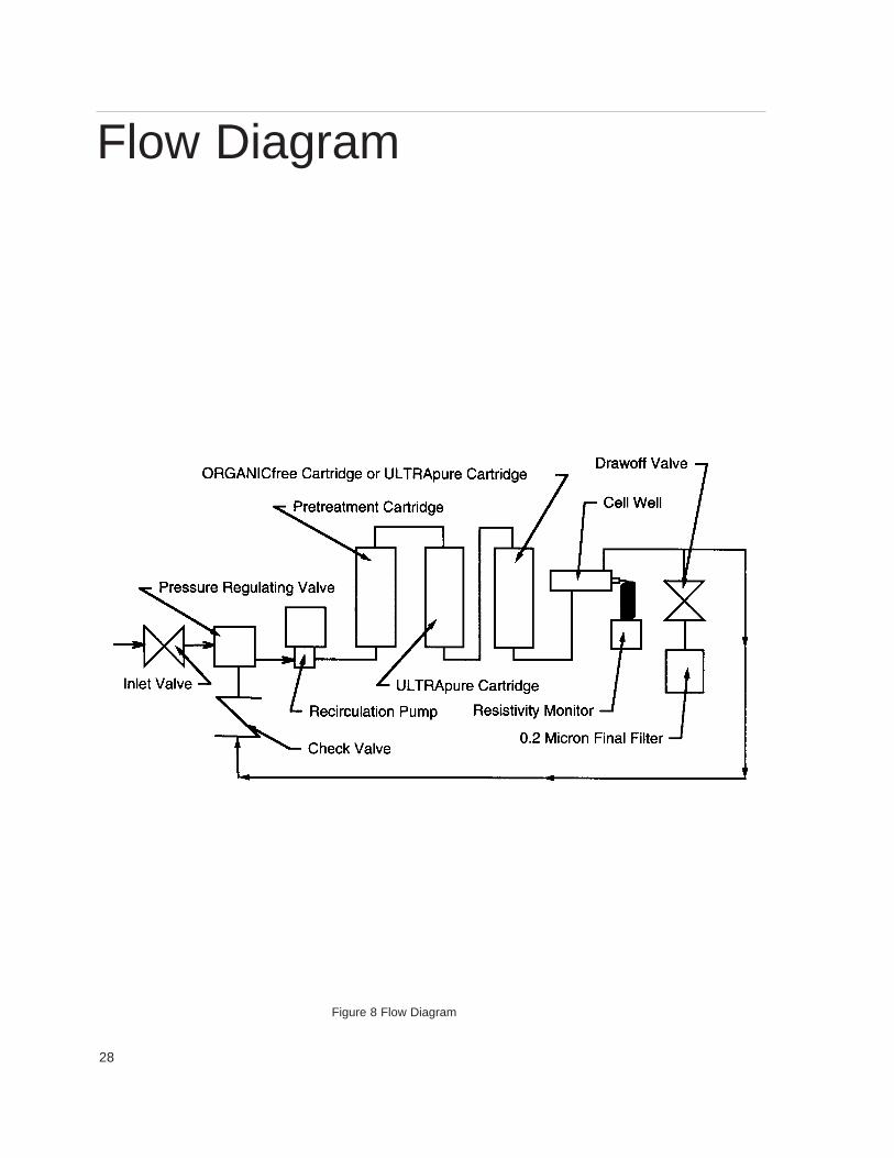
Figure 8 Flow Diagram
Flow Diagram
29
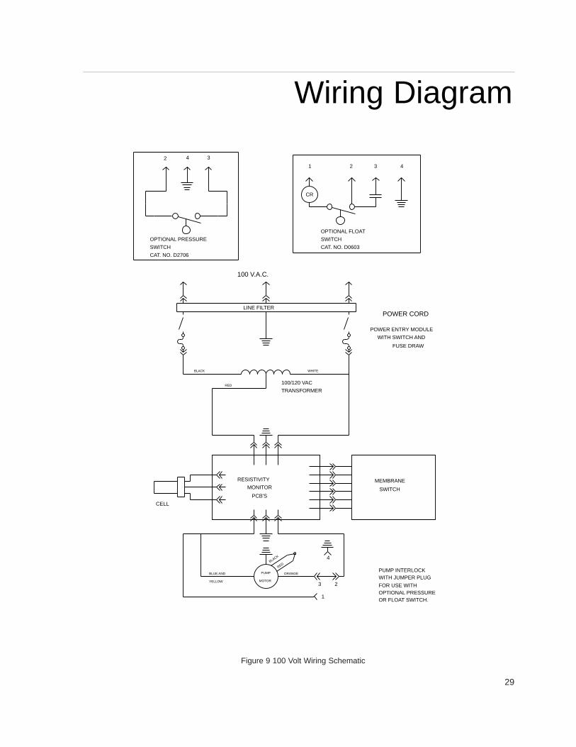
Figure 9 100 Volt Wiring Schematic
OR FLOAT SWITCH.OPTIONAL PRESSUREFOR USE WITH
WITH JUMPER PLUGPUMP INTERLOCK
FUSE DRAW
WITH SWITCH AND
POWER ENTRY MODULE
POWER CORD
MEMBRANE
BLUE AND
YELLOW
CELL
3
BLACK
MOTOR
PUMP
RED
ORANGE
MONITOR
RESISTIVITY
PCB'S
2
1
4
SWITCH
RED
BLACK
TRANSFORMER
100/120 VAC
WHITE
LINE FILTER
100 V.A.C.
4321
CAT. NO. D0603
OPTIONAL FLOAT
SWITCH
CR
CAT. NO. D2706
OPTIONAL PRESSURE
SWITCH
32 4
Wiring Diagram
WIRING DIAGRAM
30
OR FLOAT SWITCH.OPTIONAL PRESSURE
WITH JUMPER PLUGPUMP INTERLOCK
WITH SWITCH AND
POWER ENTRY MODULE
POWER CORD
OPTIONAL PRESSURE
CAT. NO. D2706SWITCH
2 4 3
YELLOW
BLUE AND
OPTIONAL FLOAT
CAT. NO. D0603
SWITCH
CR
1
ORANGE
BLACK
MOTOR
PUMP
RED
23
1
4
2 3 4
FOR USE WITH
LINE FILTER
120 V.A.C.
MONITOR
RESISTIVITY
CELL
2.0 A
PCB'S
2.0 A
MEMBRANE
SWITCH
FUSE DRAW
Figure 10 120 Volt Wiring Schematic
31
Figure 11 240 Volt Wiring Schematic
OR FLOAT SWITCH.OPTIONAL PRESSURE
WITH JUMPER PLUGPUMP INTERLOCK
WITH SWITCH AND
POWER ENTRY MODULE
POWER CORD
BLACK
OPTIONAL PRESSURE
CAT. NO. D2706
SWITCH
2 4 3
YELLOW
OPTIONAL FLOAT
CAT. NO. D0606
SWITCH
CR
1
ORANGE
BLUE
MOTOR
PUMP
RED
23
1
4
2 3 4
FOR USE WITH
LINE FILTER
240 V.A.C.
MONITOR
RESISTIVITY
CELL
1.0 A
PCB'S
1.0 A
MEMBRANE
SWITCH
FUSE DRAW
WIRING DIAGRAM
32
OR FLOAT SWITCH.OPTIONAL PRESSURE
WITH JUMPER PLUGPUMP INTERLOCK
WITH SWITCH AND
POWER ENTRY MODULE
POWER CORD
BLACK
OPTIONAL PRESSURE
CAT. NO. D2706
SWITCH
2 4 3
YELLOW
OPTIONAL FLOAT
CAT. NO. D0606
SWITCH
CR
1
ORANGE
BLUE
MOTOR
PUMP
RED
23
1
4
2 3 4
FOR USE WITH
LINE FILTER
230 V.A.C.
MONITOR
RESISTIVITY
CELL
1.0 A
PCB'S
1.0 A
MEMBRANE
SWITCH
FUSE DRAW
WIRING DIAGRAM
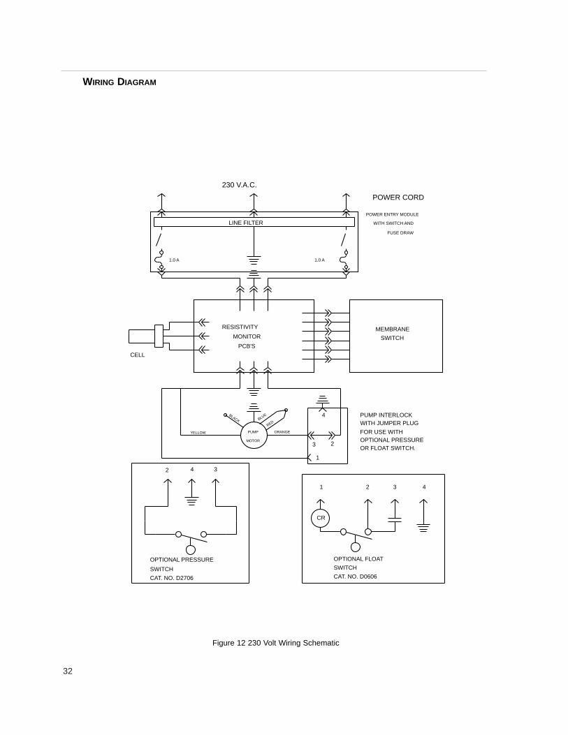
Figure 12 230 Volt Wiring Schematic

33

34

35
Barnstead|Thermolyne Corporation warrants that if a product manufactured byBarnstead|Thermolyne and sold by it within the continental United States or Canadaproves to be defective in material or construction, it will provide you, without charge, for aperiod of ninety (90) days, the labor, and a period of one (1) year, the parts, necessary toremedy any such defect. Outside the continental United States and Canada, the warrantyprovides, for one (1) year, the parts necessary to remedy any such defect. The warrantyperiod shall commence either six (6) months following the date the product is sold byBarnstead|Thermolyne or on the date it is purchased by the original retail consumer,whichever date occurs first.
All warranty inspections and repairs must be performed by and parts obtained froman authorized Barnstead|Thermolyne dealer or Barnstead|Thermolyne (at its own dis -cretion) . Heating elements, however, because of their susceptibility to overheating and con-tamination, must be returned to our factory, and if, upon inspection, it is concluded that fail-ure is not due to excessive high temperature or contamination, warranty replacement will beprovided by Barnstead|Thermolyne . The name of the authorized Barnstead|Thermolynedealer nearest you may be obtained by calling 1-800-446-6060 or writing to:
Barnstead|ThermolyneP.O. Box 797
2555 Kerper BoulevardDubuque, IA 52004-0797
USAFAX: (319) 589-0516
E-Mail: [email protected]|Thermolyne’ s sole obligation with respect to its product shall be to repair
or replace the product. Under no circumstances shall it be liable for incidental or conse-quential damage.
THE WARRANTY STATED HEREIN IS THE SOLE WARRANTY APPLICABLE TOBarnstead|Thermolyne PRODUCTS. Barnstead|Thermolyne EXPRESSLY DISCLAIMSANY AND ALL OTHER WARRANTIES, EXPRESSED OR IMPLIED, INCLUDING WAR-RANTIES OF MERCHANTABILITY OR FITNESS FOR USE.
One Year Limited Warranty

36
Barnstead Thermolyne2555 Kerper Blvd.P.O. Box 797Dubuque, IA 52004-0797 USAPHONE: 319-556-2241 • 800-553-0039FAX: 319-589-0516E-Mail: [email protected]
a subsidiary of