Embed Size (px)
Citation preview
EasyRoller GARAGE DOOR OPENER
AUTOMATIC TECHNOLOGY AUSTRALIA PTY LTD
OWNERS COPY
Installation Instructions And Owners Manual
Warning: Failure to comply with the Installation instructions and the Safety warnings may result in
Serious Personal injury and/or Property and Remote Control Opener damage.
Remote
Control
PLEASE READ THESE IMPORTANT SAFETY RULES
Failure to comply with the following Safety Rules may result in Serious Personal injury and/or Property Damage.
Automatic Technology Australia Pty Ltd to the extent that such may be lawfully excluded hereby expressly disclaims all conditions or warranties, Statu-tory or otherwise which may be implied by laws as conditions or warranties of purchase of an Automatic Technology Australia Pty Ltd EasyRoller Garage Door Opener and Automatic Technology Australia Pty Ltd hereby further expressly excludes all or any liability for any injury, damage, cost, expense or claim whatsoever suf-
2
For ADDITIONAL SAFETY protection we STRONGLY recommend the fitting of a Photo Electric beam. In most countries Photo Electric Beams are mandatory on all garage doors fitted with Automatic Openers. For a small additional outlay ATA recommends that Photo Electric Beams be installed with the Automatic Opener insuring additional safety and peace of mind. DO NOT operate the Garage Door Opener unless the Garage Door is in full view and free from objects such as cars and children/people. SERIOUS PERSONAL INJURY and / or property damage can result from failure to follow this warning. DO NOT operate the Garage Door Opener when children/persons are near the door. Children must be su-pervised near garage door at all time and when Door Opener is in use. SERIOUS PERSONAL INJURY and / or property damage can result from failure to follow the warning. DO NOT allow children to operate the Garage Door Opener. SERIOUS PERSONAL INJURY and/or property damage can result from failure to follow this warning. Make sure that the SAFETY OBSTRUCTION FORCE is working correctly, and is TESTED and set as per the Installation Instructions Manual. Failure to follow the Manual could result in SERIOUS PERSONAL INJURY and/or property damage. This test must be repeated at regular intervals and the necessary adjustments made if required. DO NOT disengage the Door Opener to manual operation with children/persons or any other objects including motor vehicle within the doorway. Install the wall switch or wall mounted transmitter in a LOCATION / POSITION where the garage door is visible and out of reach of children.
The Garage door must be WELL BALANCED. Sticking or binding doors must be repaired by a qualified garage door installer prior to Opener installation. DO NOT attempt to repair door yourself as hardware is under extreme tension and can cause SERIOUS PERSONAL INJURY and/or property damage. REMOVE OR DISENGAGE all garage doors locks and mechanisms prior to installation of Opener. Connect the Garage Door Opener to a properly EARTHED general purpose 240V outlet installed by a qualified electrical contractor. DISCONNECT THE POWER CORD from main power before making any repairs or removing covers. Only EXPERIENCED service personnel can remove covers from Opener. Keep hands and loose clothing CLEAR of the door and Door Opener at all times. When using auto close mode a PHOTO ELECTRIC BEAM must be fitted correctly and tested for operation at regular intervals. EXTREME CAUTION is recommend when using auto close mode. All SAFETY RULES above must be followed. In order for the Garage Door Opener to SENSE an ob-ject obstructing the door way, some FORCE must be exerted on the object. As a result the object, door and/or person may suffer DAMAGE or INJURY . Make sure that the door is fully open before driving into or out of the garage. Make sure the door is fully closed before leaving the driveway.
Your Easy Roller Automatic Garage Door Opener has many features which you will appreciate. The components and materials used in this Automatic Opener are of the latest technology and highest qual-ity. Below are listed some of the many features. OPERATION To operate the door simply press the hand held transmitter or the wall mounted transmitter or optional wall switch for two seconds and the door will automatically open or close. The door can be stopped during an opening or closing cycle by pressing again. The next actuation will move the door in the opposite direction. HOPPING CODE Every time a transmission is made from the Remote Transmitter a new security code is generated. The n u mb e r o f p o s s i b l e c o d e combinations is over 4.29 billion. This greatly enhances security of the system. Code ’Grabbing’ is made a thing of the past. ISS (INTELLIGENT SAFETY OBSTRUCTION SYSTEM) While the door is doing a closing cycle and if it should hit an obstacle or be restricted in some manner, it will automatically reverse. The amount of force the door should encounter before reversing, is automatically adjusted by the doors control system, during the initial installation of the automatic door opener. The door also if restricted whilst opening will stop. The Safety Obstruction Force should be checked at least once a month. See installation manual for instructions. SECURITY CODE STORE The Opener uses state of the art technology in storing your selected Transmitter Security Code. Up to 27 different codes can be stored in the Openers memory.
OPEN AND CLOSE DRIVE BUTTONS Another feature developed by Automatic Technology Australia in aiding in the installation of the opener is the Open and Close Drive Buttons. These buttons are used to help set the open and close limit positions. A quicker setting time and a more precise limit position can be achieved using this system. INITIALISATION The Reset button on the Door Opener is used to initialise or re-initialise the obstruction settings and door travel counts. See installation manual for instructions. AUTO CLOSE MODE The Opener can be programmed to automatically close after an open cycle. The Auto Close time is adjustable. It is compulsory to in-stall a Photo Electric Beam if this mode is selected, otherwise the door will not operate. SAFETY AUTO RUN TIME If the Opener does not complete its cycle within thirty seconds the Opener will stop if opening, and reverse back open if closing automatically. PHOTO ELECTRIC BEAM (OPTIONAL) The Opener has an input for a Photo Electric Beam to be connected for extra safety protection. And use of the Auto Close Mode MANUAL OPERATION The Opener is equipped with a unique Manual Disengaging Device. If the power to the Opener is disrupted for any reason the door can be put into Manual Mode by pulling down on the string handle, then releasing. This will allow you to manually open or close the door. When power is restored, by pulling down on the string handle and releasing, the opener is put back into Automatic Mode.
To store any code simply press and hold the Door Code button on the Opener and press the Transmitter button twice. Each or all codes can be deleted and changed at any time. The codes can also be stored with the Transmitter from a remote location. OVER LOAD INDICATOR When the maximum opening and closing capacity of the Opener is exceeded the Courtesy Light will flash about 10 times and an au-dible Beeper will sound to indicate that an Overload has occurred. SERVICE INDICATOR The Opener has a Service indicator. When the Overload LED light flashes and the beeper sounds at the start of a door cycle, it means that the opener and or garage door needs a service. AUTO COURTESY LIGHT The Courtesy Light on the Opener comes on automatically whenever the door is activated to do an opening or closing cycle. The Light can also be switched on and off without operat-ing the door. This is done by pressing the button on any Hand Held Trans-mitter or Wall Mounted Transmitter which has been stored with the light code, or by pressing the light button on the Wall Switch (optional). The light will stay on for approxi-mately three minutes then go off. This time is also adjustable. CAS (COLOUR ASSISTED SETTINGS) To make the installation of the Automatic Opener more user friendly Automatic Technology Australia developed the CAS (Colour Assisted Settings) system. This unique system allows for all the Open and Close adjustments and settings to be colour coordinated, Red for Close and Green for Open. The colour coordination make its easier and quicker for the user or installer to complete the installation.
FEATURES
3
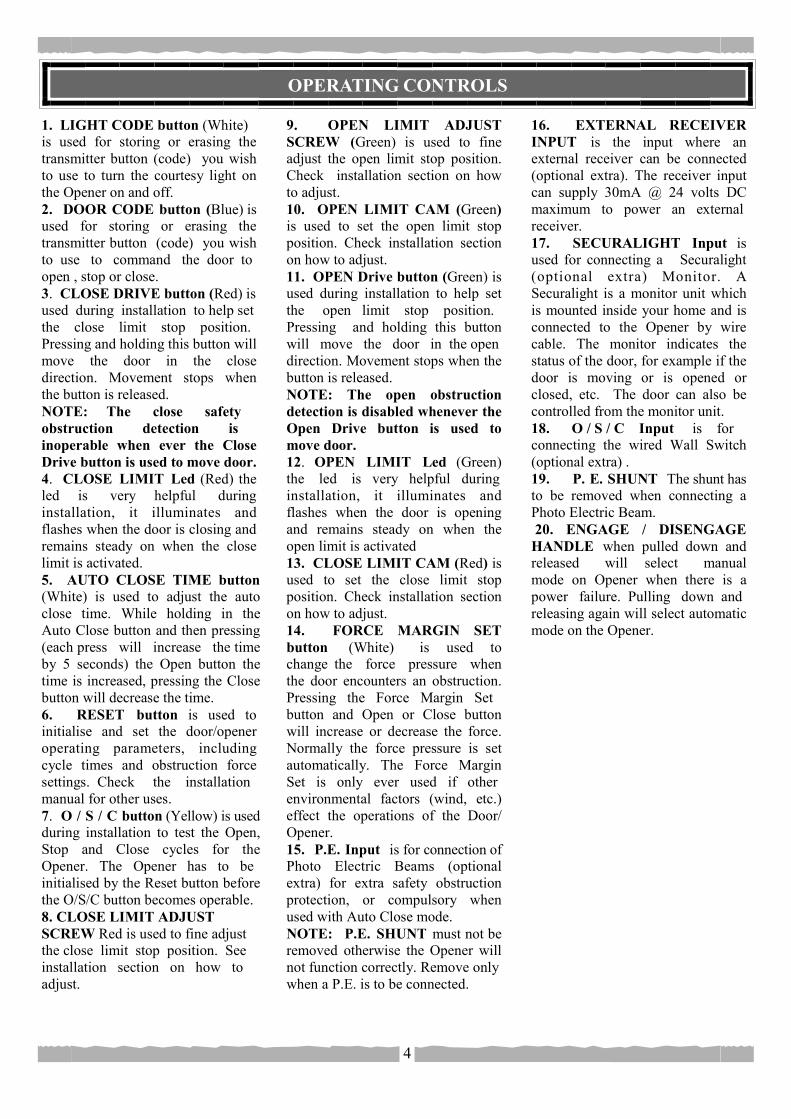
1. LIGHT CODE button (White) is used for storing or erasing the transmitter button (code) you wish to use to turn the courtesy light on the Opener on and off. 2. DOOR CODE button (Blue) is used for storing or erasing the transmitter button (code) you wish to use to command the door to open , stop or close. 3. CLOSE DRIVE button (Red) is used during installation to help set the close limit stop position. Pressing and holding this button will move the door in the close direction. Movement stops when the button is released. NOTE: The close safety obstruction detection is inoperable when ever the Close Drive button is used to move door. 4. CLOSE LIMIT Led (Red) the led is very helpful during installation, it illuminates and flashes when the door is closing and remains steady on when the close limit is activated. 5. AUTO CLOSE TIME button (White) is used to adjust the auto close time. While holding in the Auto Close button and then pressing (each press will increase the time by 5 seconds) the Open button the time is increased, pressing the Close button will decrease the time. 6. RESET button is used to initialise and set the door/opener operating parameters, including cycle times and obstruction force settings. Check the installation manual for other uses. 7. O / S / C button (Yellow) is used during installation to test the Open, Stop and Close cycles for the Opener. The Opener has to be initialised by the Reset button before the O/S/C button becomes operable. 8. CLOSE LIMIT ADJUST SCREW Red is used to fine adjust the close limit stop position. See installation section on how to adjust.
16. EXTERNAL RECEIVER INPUT is the input where an external receiver can be connected (optional extra). The receiver input can supply 30mA @ 24 volts DC maximum to power an external receiver. 17. SECURALIGHT Input is used for connecting a Securalight (optional extra) Monitor. A Securalight is a monitor unit which is mounted inside your home and is connected to the Opener by wire cable. The monitor indicates the status of the door, for example if the door is moving or is opened or closed, etc. The door can also be controlled from the monitor unit. 18. O / S / C Input is for connecting the wired Wall Switch (optional extra) . 19. P. E. SHUNT The shunt has to be removed when connecting a Photo Electric Beam. 20. ENGAGE / DISENGAGE HANDLE when pulled down and released will select manual mode on Opener when there is a power failure. Pulling down and releasing again will select automatic mode on the Opener.
9. OPEN LIMIT ADJUST SCREW (Green) is used to fine adjust the open limit stop position. Check installation section on how to adjust. 10. OPEN LIMIT CAM (Green) is used to set the open limit stop position. Check installation section on how to adjust. 11. OPEN Drive button (Green) is used during installation to help set the open limit stop position. Pressing and holding this button will move the door in the open direction. Movement stops when the button is released. NOTE: The open obstruction detection is disabled whenever the Open Drive button is used to move door. 12. OPEN LIMIT Led (Green) the led is very helpful during installation, it illuminates and flashes when the door is opening and remains steady on when the open limit is activated 13. CLOSE LIMIT CAM (Red) is used to set the close limit stop position. Check installation section on how to adjust. 14. FORCE MARGIN SET button (White) is used to change the force pressure when the door encounters an obstruction. Pressing the Force Margin Set button and Open or Close button will increase or decrease the force. Normally the force pressure is set automatically. The Force Margin Set is only ever used if other environmental factors (wind, etc.) effect the operations of the Door/Opener. 15. P.E. Input is for connection of Photo Electric Beams (optional extra) for extra safety obstruction protection, or compulsory when used with Auto Close mode. NOTE: P.E. SHUNT must not be removed otherwise the Opener will not function correctly. Remove only when a P.E. is to be connected.
OPERATING CONTROLS
4
3 4 521
18
6 7 8 9 11 12 14
20
10 13
19
171615
OPERATING CONTROLS
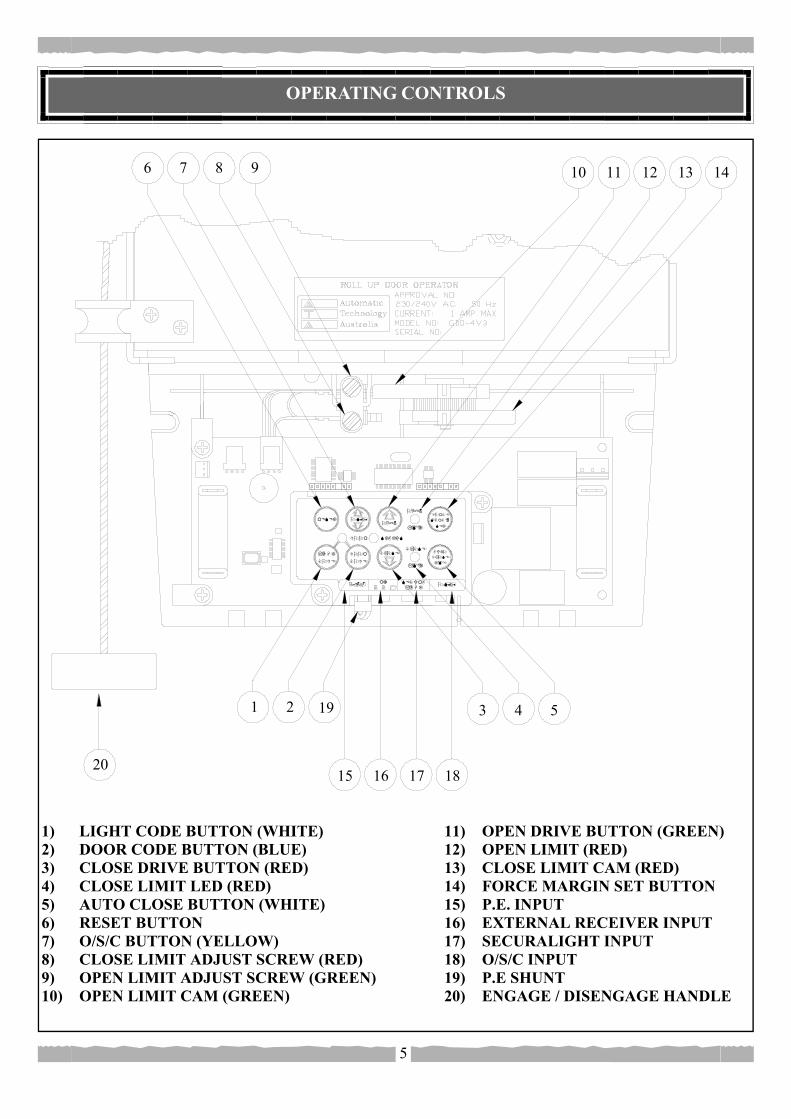
1) LIGHT CODE BUTTON (WHITE) 2) DOOR CODE BUTTON (BLUE) 3) CLOSE DRIVE BUTTON (RED) 4) CLOSE LIMIT LED (RED) 5) AUTO CLOSE BUTTON (WHITE) 6) RESET BUTTON 7) O/S/C BUTTON (YELLOW) 8) CLOSE LIMIT ADJUST SCREW (RED) 9) OPEN LIMIT ADJUST SCREW (GREEN) 10) OPEN LIMIT CAM (GREEN)
11) OPEN DRIVE BUTTON (GREEN) 12) OPEN LIMIT (RED) 13) CLOSE LIMIT CAM (RED) 14) FORCE MARGIN SET BUTTON 15) P.E. INPUT 16) EXTERNAL RECEIVER INPUT 17) SECURALIGHT INPUT 18) O/S/C INPUT 19) P.E SHUNT 20) ENGAGE / DISENGAGE HANDLE
5
PACKAGE CONTENTS
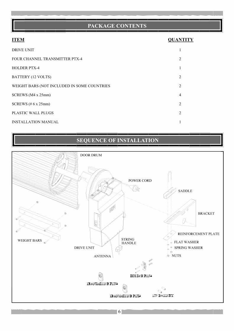
ITEM QUANTITY DRIVE UNIT 1 FOUR CHANNEL TRANSMITTER PTX-4 2 HOLDER PTX-4 1 BATTERY (12 VOLTS) 2 WEIGHT BARS (NOT INCLUDED IN SOME COUNTRIES 2 SCREWS (M4 x 25mm) 4 SCREWS (# 6 x 25mm) 2 PLASTIC WALL PLUGS 2 INSTALLATION MANUAL 1
6
SEQUENCE OF INSTALLATION
INSTALLATION
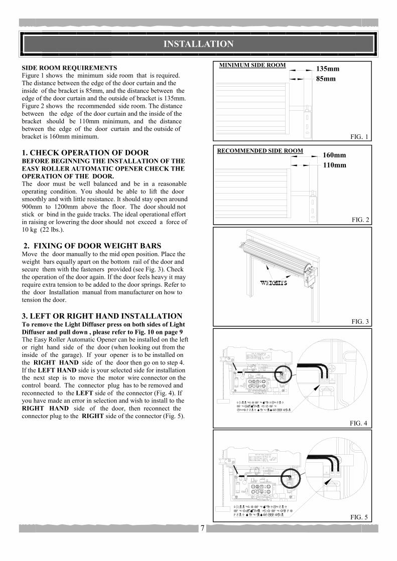
SIDE ROOM REQUIREMENTS Figure 1 shows the minimum side room that is required. The distance between the edge of the door curtain and the inside of the bracket is 85mm, and the distance between the edge of the door curtain and the outside of bracket is 135mm. Figure 2 shows the recommended side room. The distance between the edge of the door curtain and the inside of the bracket should be 110mm minimum, and the distance between the edge of the door curtain and the outside of bracket is 160mm minimum. 1. CHECK OPERATION OF DOOR BEFORE BEGINNING THE INSTALLATION OF THE EASY ROLLER AUTOMATIC OPENER CHECK THE OPERATION OF THE DOOR. The door must be well balanced and be in a reasonable operating condition. You should be able to lift the door smoothly and with little resistance. It should stay open around 900mm to 1200mm above the floor. The door should not stick or bind in the guide tracks. The ideal operational effort in raising or lowering the door should not exceed a force of 10 kg (22 lbs.). 2. FIXING OF DOOR WEIGHT BARS Move the door manually to the mid open position. Place the weight bars equally apart on the bottom rail of the door and secure them with the fasteners provided (see Fig. 3). Check the operation of the door again. If the door feels heavy it may require extra tension to be added to the door springs. Refer to the door Installation manual from manufacturer on how to tension the door. 3. LEFT OR RIGHT HAND INSTALLATION To remove the Light Diffuser press on both sides of Light Diffuser and pull down , please refer to Fig. 10 on page 9 The Easy Roller Automatic Opener can be installed on the left or right hand side of the door (when looking out from the inside of the garage). If your opener is to be installed on the RIGHT HAND side of the door then go on to step 4. If the LEFT HAND side is your selected side for installation the next step is to move the motor wire connector on the control board. The connector plug has to be removed and reconnected to the LEFT side of the connector (Fig. 4). If you have made an error in selection and wish to install to the RIGHT HAND side of the door, then reconnect the connector plug to the RIGHT side of the connector (Fig. 5).
7
RECOMMENDED SIDE ROOM 160mm 110mm
MINIMUM SIDE ROOM 135mm 85mm
FIG. 5
FIG. 4
FIG. 3
FIG. 1
FIG. 2

INSTALLATION cont...
8
4. FIXING DRIVE ASSEMBLY TO THE DOOR (RIGHT HAND INSTALLATION) The Easy Roller Drive Assembly can be fixed to the Roll Up Garage Door in a variety of ways. Below we will describe one method of fixing. Make sure there is enough side room (135mm from end of door shaft to the wall) to slide Drive Assembly onto shaft. PLEASE NOTE : THE INSTRUCTIONS FOR FIXING OF THE DRIVE ASSEMBLY TO THE DOOR IS FOR RIGHT HAND INSTALLATION. FITTING DRIVE ASSEMBLY TO DOOR ( Fig. 6, Fig. 7, and Fig. 8 ). 1. Check that the door shaft U bolt is securely tightened on the left hand side of the door. 2. Raise the door and tie a rope around the centre to secure the roll. 3. Support the right hand end of the door with a suitable prop, e.g. step ladder and soft padding to protect door surface. STOP. WARNING: DO NOT ALLOW CHILDREN/PERSONS AROUND THE DOOR AND PROP. SERIOUS PERSONAL INJURY AND / OR PROP-ERTY DAMAGE CAN RESULT FROM FAIL-URE TO FOLLOW THIS WARNING. 4. Check that Step 3. was completed. Carefully loosen and remove the right hand door shaft U bolt. 5. Make sure that the door supporting prop is secure. While the door is supported remove the right hand door mounting bracket from wall. 6. Remove the Drive Assembly from packaging. Try and rotate the drive gear by pushing on the fork. If the gear does not rotate the manual mode has to be selected. To select pull on the string handle downwards, then release slowly. The drive gear should now rotate. 7. Slide the Drive Assembly over the door axle making sure that the fork extends into and over one of the spokes of the door drum wheel. 8. Refit the door mounting bracket to the wall. In some cases the bracket may have to be re-positioned. Re-tighten the door shaft U bolt. Remove door supporting prop and untie rope from curtain. 9. Straighten the Drive Assembly and position as per Fig. 8. Tighten the two locking bolts firmly to secure the Drive Assembly. 10. Check the manual operation of the door by raising and lowering the door. The door should run smoothly and not catch on any part of the Drive Assembly.
FIG. 8
(1)
(2)
(3)
(4)
(5)
(6)
(7)
(8)
(9)
(8)
(8)
FIG. 7
FIG. 6
INSTALLATION cont...
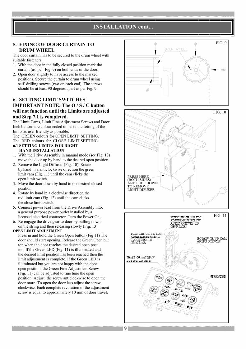
5. FIXING OF DOOR CURTAIN TO DRUM WHEEL The door curtain has to be secured to the drum wheel with suitable fasteners. 1. With the door in the fully closed position mark the curtain (as per Fig. 9) on both ends of the door. 2. Open door slightly to have access to the marked positions. Secure the curtain to drum wheel using self drilling screws (two on each end). The screws should be at least 90 degrees apart as per Fig. 9. 6. SETTING LIMIT SWITCHES IMPORTANT NOTE: The O / S / C button will not function until the Limits are adjusted and Step 7.1 is completed. The Limit Cams, Limit Fine Adjustment Screws and Door Inch buttons are colour coded to make the setting of the limits as user friendly as possible. The GREEN colours for OPEN LIMIT SETTING. The RED colours for CLOSE LIMIT SETTING. 6.1 SETTING LIMITS FOR RIGHT HAND INSTALLATION 1. With the Drive Assembly in manual mode (see Fig. 13) move the door up by hand to the desired open position. 2. Remove the Light Diffuser (Fig. 10). Rotate by hand in a anticlockwise direction the green limit cam (Fig. 11) until the cam clicks the open limit switch. 3. Move the door down by hand to the desired closed position. 4. Rotate by hand in a clockwise direction the red limit cam (Fig. 12) until the cam clicks the close limit switch. 5. Connect power lead from the Drive Assembly into, a general purpose power outlet installed by a licensed electrical contractor. Turn the Power On. 6. Re-engage the drive gear to door by pulling down on the string and then releasing slowly (Fig. 13). OPEN LIMIT ADJUSTMENT Press in and hold the Green Open button (Fig 11) The door should start opening. Release the Green Open but ton when the door reaches the desired open post ion. If the Green LED (Fig. 11) is illuminated and the desired limit position has been reached then the limit adjustment is complete. If the Green LED is illuminated but you are not happy with the door open position, the Green Fine Adjustment Screw (Fig. 11) can be adjusted to fine tune the open position. Adjust the screw anticlockwise to open the door more. To open the door less adjust the screw clockwise. Each complete revolution of the adjustment screw is equal to approximately 10 mm of door travel.
9
FIG. 10
FIG. 9
FIG. 11

INSTALLATION cont...
NOTE: If the door has not reached the desired limit position by more then 30 mm, then it is recommended that the green limits cam be adjusted again before the green fine adjustment screw is adjusted. CLOSE LIMIT ADJUSTMENT Press in and hold the Red Close button. (Fig 12) The door should start closing. Release the Red Close button when the door reaches the desired closed position. If the Red LED Fig. 12) is illuminated and the desired limit position has been reached then the limit adjustment is complete. If the Red LED is illuminated but you are not happy with the door close position, the Red Fine Adjustment Screw (Fig. 12) can be adjusted to fine tune the close position. Adjust the screw anticlockwise to close the door less. To close the door more adjust the Red Fine Adjustment Screw clockwise. Each complete revolution of the adjustment screw is equal to approximately 10 mm of door travel. NOTE: If the door has not reached the desired limit position by more then 30 mm, then it is recommended that the red limits cam be adjusted again before the red fine adjustment screw is adjusted. 6.2 SETTING LIMITS FOR LEFT HAND INSTALLATION 1. With the Drive Assembly in manual mode (see Fig. 13) move the door up by hand to the desired open position. 2. Remove the Light Diffuser (Fig. 10). Rotate by hand in a clockwise direction the Green Limit Cam (Fig. 14) until the cam clicks the open limit switch. 3. Move the door down by hand to the desired closed position. 4. Rotate by hand in a anticlockwise direction the red limit cam (Fig. 15) until the cam clicks the close limit switch. 5. Connect Power Lead from the Drive Assembly into, a general purpose power outlet installed by a licensed qualified electrical contractor. Make sure that the Power Lead is safely fastened away from any moving parts. Turn the Power On. 6. Re-engage the drive gear to door by pulling down on the string handle and hen releasing slowly (Fig. 13).
10
FIG. 12
FIG. 13
INSTALLATION cont...
11
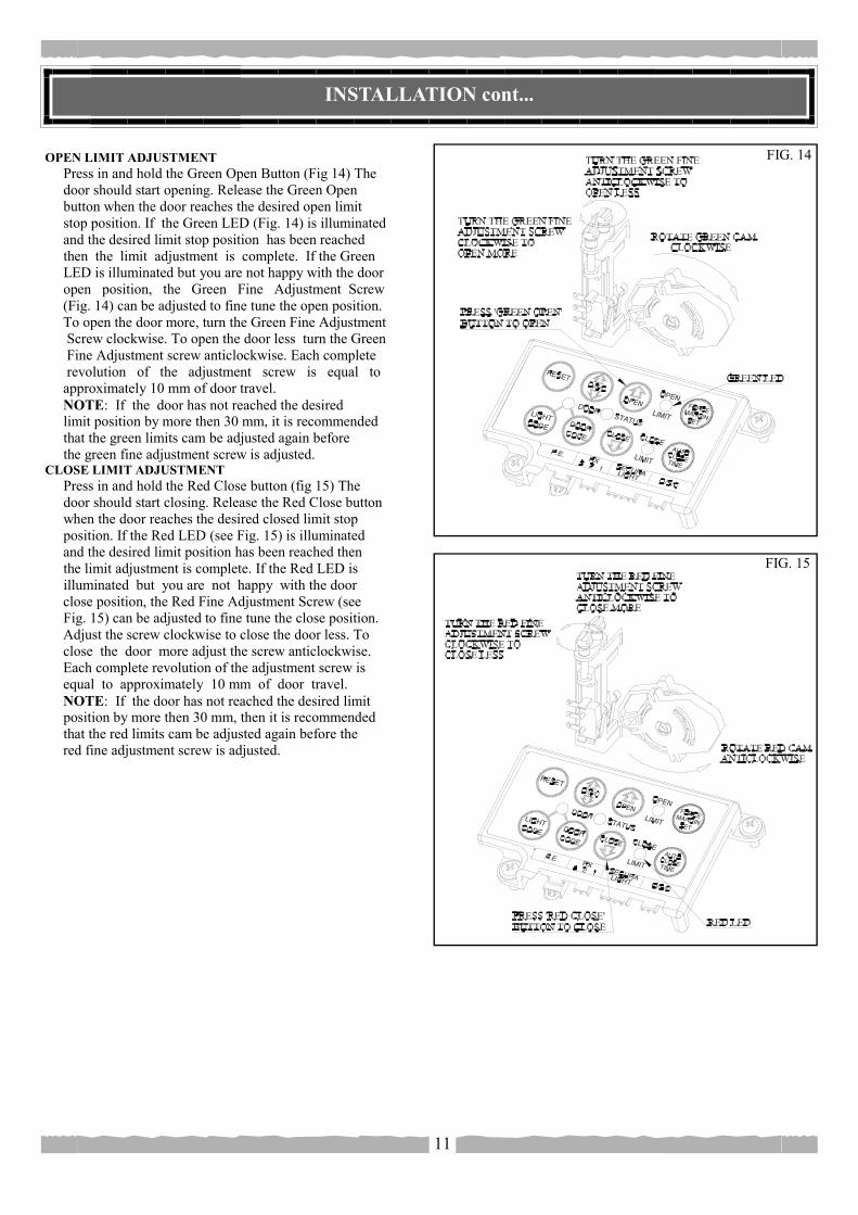
OPEN LIMIT ADJUSTMENT Press in and hold the Green Open Button (Fig 14) The door should start opening. Release the Green Open button when the door reaches the desired open limit stop position. If the Green LED (Fig. 14) is illuminated and the desired limit stop position has been reached then the limit adjustment is complete. If the Green LED is illuminated but you are not happy with the door open position, the Green Fine Adjustment Screw (Fig. 14) can be adjusted to fine tune the open position. To open the door more, turn the Green Fine Adjustment Screw clockwise. To open the door less turn the Green Fine Adjustment screw anticlockwise. Each complete revolution of the adjustment screw is equal to approximately 10 mm of door travel. NOTE: If the door has not reached the desired limit position by more then 30 mm, it is recommended that the green limits cam be adjusted again before the green fine adjustment screw is adjusted. CLOSE LIMIT ADJUSTMENT Press in and hold the Red Close button (fig 15) The door should start closing. Release the Red Close button when the door reaches the desired closed limit stop position. If the Red LED (see Fig. 15) is illuminated and the desired limit position has been reached then the limit adjustment is complete. If the Red LED is illuminated but you are not happy with the door close position, the Red Fine Adjustment Screw (see Fig. 15) can be adjusted to fine tune the close position. Adjust the screw clockwise to close the door less. To close the door more adjust the screw anticlockwise. Each complete revolution of the adjustment screw is equal to approximately 10 mm of door travel. NOTE: If the door has not reached the desired limit position by more then 30 mm, then it is recommended that the red limits cam be adjusted again before the red fine adjustment screw is adjusted.
FIG. 14
FIG. 15
INSTALLATION cont...
12
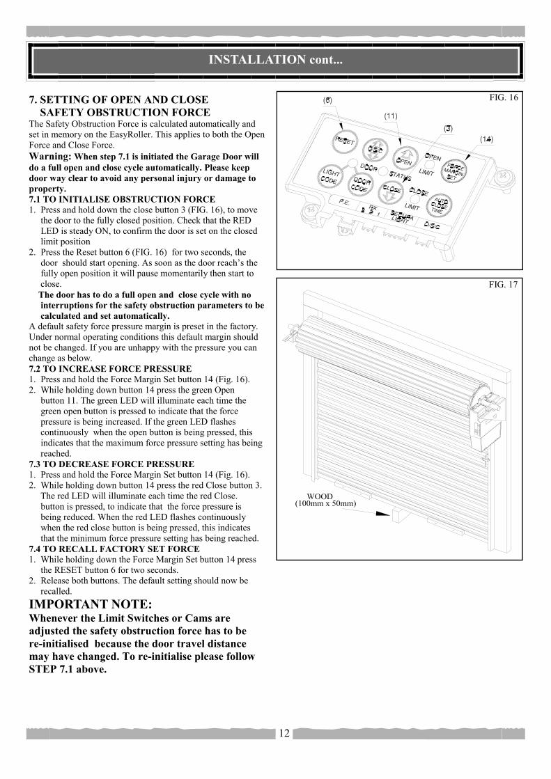
7. SETTING OF OPEN AND CLOSE SAFETY OBSTRUCTION FORCE The Safety Obstruction Force is calculated automatically and set in memory on the EasyRoller. This applies to both the Open Force and Close Force. Warning: When step 7.1 is initiated the Garage Door will do a full open and close cycle automatically. Please keep door way clear to avoid any personal injury or damage to property. 7.1 TO INITIALISE OBSTRUCTION FORCE 1. Press and hold down the close button 3 (FIG. 16), to move the door to the fully closed position. Check that the RED LED is steady ON, to confirm the door is set on the closed limit position 2. Press the Reset button 6 (FIG. 16) for two seconds, the door should start opening. As soon as the door reach’s the fully open position it will pause momentarily then start to close. The door has to do a full open and close cycle with no interruptions for the safety obstruction parameters to be calculated and set automatically. A default safety force pressure margin is preset in the factory. Under normal operating conditions this default margin should not be changed. If you are unhappy with the pressure you can change as below. 7.2 TO INCREASE FORCE PRESSURE 1. Press and hold the Force Margin Set button 14 (Fig. 16). 2. While holding down button 14 press the green Open button 11. The green LED will illuminate each time the green open button is pressed to indicate that the force pressure is being increased. If the green LED flashes continuously when the open button is being pressed, this indicates that the maximum force pressure setting has being reached. 7.3 TO DECREASE FORCE PRESSURE 1. Press and hold the Force Margin Set button 14 (Fig. 16). 2. While holding down button 14 press the red Close button 3. The red LED will illuminate each time the red Close. button is pressed, to indicate that the force pressure is being reduced. When the red LED flashes continuously when the red close button is being pressed, this indicates that the minimum force pressure setting has being reached. 7.4 TO RECALL FACTORY SET FORCE 1. While holding down the Force Margin Set button 14 press the RESET button 6 for two seconds. 2. Release both buttons. The default setting should now be recalled. IMPORTANT NOTE: Whenever the Limit Switches or Cams are adjusted the safety obstruction force has to be re-initialised because the door travel distance may have changed. To re-initialise please follow STEP 7.1 above.
FIG. 17
FIG. 16
INSTALLATION cont.
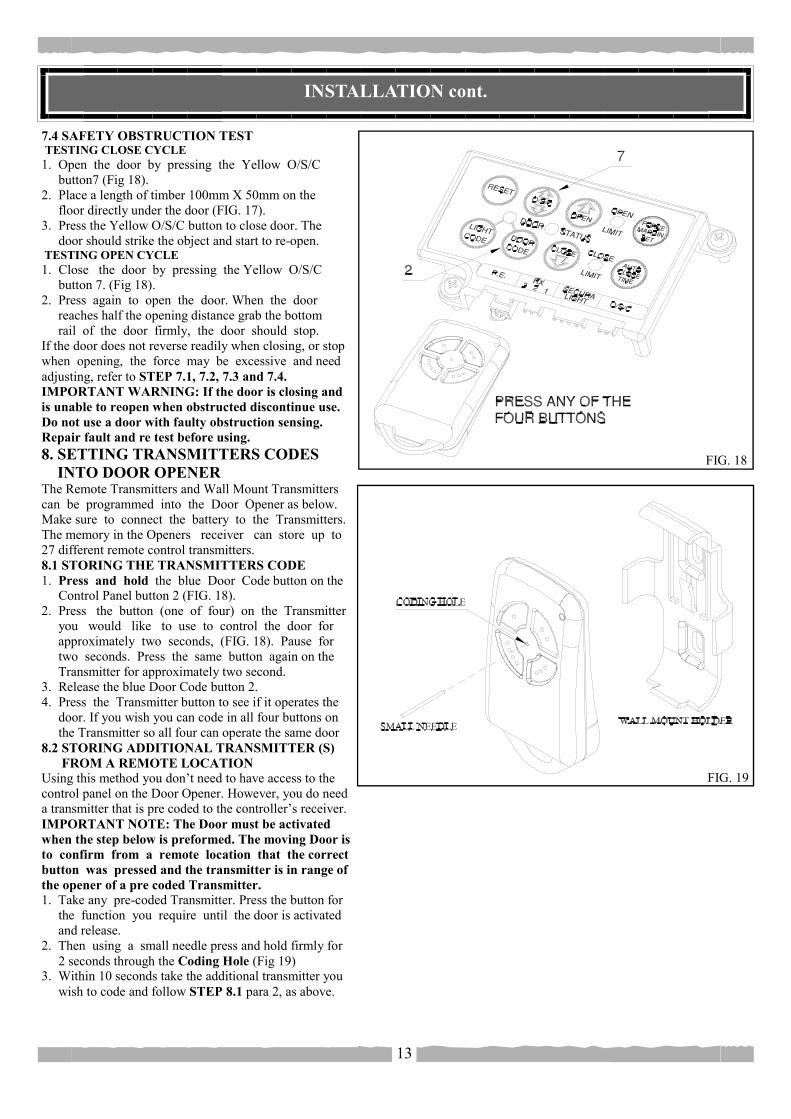
7.4 SAFETY OBSTRUCTION TEST TESTING CLOSE CYCLE 1. Open the door by pressing the Yellow O/S/C button7 (Fig 18). 2. Place a length of timber 100mm X 50mm on the floor directly under the door (FIG. 17). 3. Press the Yellow O/S/C button to close door. The door should strike the object and start to re-open. TESTING OPEN CYCLE 1. Close the door by pressing the Yellow O/S/C button 7. (Fig 18). 2. Press again to open the door. When the door reaches half the opening distance grab the bottom rail of the door firmly, the door should stop. If the door does not reverse readily when closing, or stop when opening, the force may be excessive and need adjusting, refer to STEP 7.1, 7.2, 7.3 and 7.4. IMPORTANT WARNING: If the door is closing and is unable to reopen when obstructed discontinue use. Do not use a door with faulty obstruction sensing. Repair fault and re test before using. 8. SETTING TRANSMITTERS CODES INTO DOOR OPENER The Remote Transmitters and Wall Mount Transmitters can be programmed into the Door Opener as below. Make sure to connect the battery to the Transmitters. The memory in the Openers receiver can store up to 27 different remote control transmitters. 8.1 STORING THE TRANSMITTERS CODE 1. Press and hold the blue Door Code button on the Control Panel button 2 (FIG. 18). 2. Press the button (one of four) on the Transmitter you would like to use to control the door for approximately two seconds, (FIG. 18). Pause for two seconds. Press the same button again on the Transmitter for approximately two second. 3. Release the blue Door Code button 2. 4. Press the Transmitter button to see if it operates the door. If you wish you can code in all four buttons on the Transmitter so all four can operate the same door 8.2 STORING ADDITIONAL TRANSMITTER (S) FROM A REMOTE LOCATION Using this method you don’t need to have access to the control panel on the Door Opener. However, you do need a transmitter that is pre coded to the controller’s receiver. IMPORTANT NOTE: The Door must be activated when the step below is preformed. The moving Door is to confirm from a remote location that the correct button was pressed and the transmitter is in range of the opener of a pre coded Transmitter. 1. Take any pre-coded Transmitter. Press the button for the function you require until the door is activated and release. 2. Then using a small needle press and hold firmly for 2 seconds through the Coding Hole (Fig 19) 3. Within 10 seconds take the additional transmitter you wish to code and follow STEP 8.1 para 2, as above.
13
FIG. 19
FIG. 18
INSTALLATION cont...
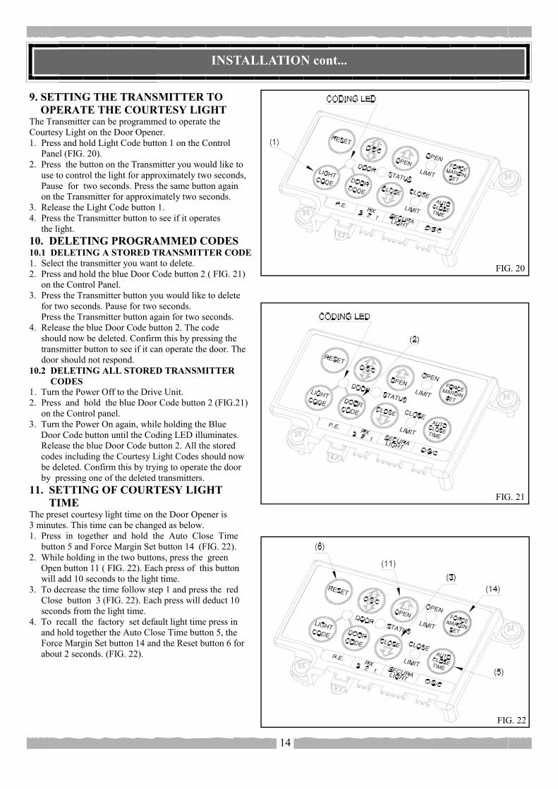
9. SETTING THE TRANSMITTER TO OPERATE THE COURTESY LIGHT The Transmitter can be programmed to operate the Courtesy Light on the Door Opener. 1. Press and hold Light Code button 1 on the Control Panel (FIG. 20). 2. Press the button on the Transmitter you would like to use to control the light for approximately two seconds, Pause for two seconds. Press the same button again on the Transmitter for approximately two seconds. 3. Release the Light Code button 1. 4. Press the Transmitter button to see if it operates the light. 10. DELETING PROGRAMMED CODES 10.1 DELETING A STORED TRANSMITTER CODE 1. Select the transmitter you want to delete. 2. Press and hold the blue Door Code button 2 ( FIG. 21) on the Control Panel. 3. Press the Transmitter button you would like to delete for two seconds. Pause for two seconds. Press the Transmitter button again for two seconds. 4. Release the blue Door Code button 2. The code should now be deleted. Confirm this by pressing the transmitter button to see if it can operate the door. The door should not respond. 10.2 DELETING ALL STORED TRANSMITTER CODES 1. Turn the Power Off to the Drive Unit. 2. Press and hold the blue Door Code button 2 (FIG.21) on the Control panel. 3. Turn the Power On again, while holding the Blue Door Code button until the Coding LED illuminates. Release the blue Door Code button 2. All the stored codes including the Courtesy Light Codes should now be deleted. Confirm this by trying to operate the door by pressing one of the deleted transmitters. 11. SETTING OF COURTESY LIGHT TIME The preset courtesy light time on the Door Opener is 3 minutes. This time can be changed as below. 1. Press in together and hold the Auto Close Time button 5 and Force Margin Set button 14 (FIG. 22). 2. While holding in the two buttons, press the green Open button 11 ( FIG. 22). Each press of this button will add 10 seconds to the light time. 3. To decrease the time follow step 1 and press the red Close button 3 (FIG. 22). Each press will deduct 10 seconds from the light time. 4. To recall the factory set default light time press in and hold together the Auto Close Time button 5, the Force Margin Set button 14 and the Reset button 6 for about 2 seconds. (FIG. 22).
14
FIG. 21
FIG. 20
FIG. 22

INSTALLATION cont...
12. FITTING OF SAFETY PHOTO ELECTRIC BEAM (OPTIONAL) Locate the Photo Electric Beam (P.E.) normally closed contact type in a strategic location within doorway. Remove shunt from P.E connector (FIG.23) and connect the plug from the P.E. wiring harness to P.E. connector 15 (FIG.24). Follow the wiring diagram supplied with the P.E. for wiring of the P.E. WARNING; When using auto close and P.E. beams, the doorway must be clear of all obstructions and persons at all times. The location of the beam and manner in which it is installed might not give safety protection at all times. Check to make sure that the height of the beam and type used give maximum protection possible. 13. SETTING OF AUTO CLOSE TIME IMPORTANT NOTICE: IT IS COMPULSORY TO INSTALL A PHOTO ELECTRIC BEAM BEFORE USING THE AUTO CLOSE MODE. The Auto Close timer will only start after the Photo Electric Beams (P.E.) path is broken and the auto close time has been set. If the P.E. path is not broken the door will remain open till the path is broken. If the Door Opener incurs an obstruction (not from the P.E.) while closing the door will re-open and not auto close. After the setting of the auto close mode, whenever the door is in the open position the open limit green LED will flash to indicate that the auto close mode is in operation. SETTING AUTO CLOSE TIME 1. Press in and hold the Auto Close Time button 5 (FIG. 25). 2. While holding in the Auto Close Time button, press the green Open button 11 (FIG. 25). Each press of this button will add 5 seconds to the preset auto close time of ‘0‘ seconds. 3. To decrease the time follow step 1 and press the red Close button 3. Each press will deduct 5 seconds from the auto close time. 4. Press the O/S/C button 7 (FIG. 25) or Transmitter to open the door. While the door is opening break the path of the P.E. Beam, this will initialise the auto close mode. When the door reaches the fully opened position, the door will pause for the set auto close time and start to auto close. 14. INSTALLATION OF WALL MOUNTED TRANSMITTER HOLDER 1. Mount the holder in a location out of reach of children and convenient to the customer. (Fig 19) 2. The transmitter can be easily clipped in and removed from the holder anytime. 3. To set the transmitter codes refer to Step 8.
15
FIG. 23
FIG. 24
FIG. 25
INSTALLATION cont...
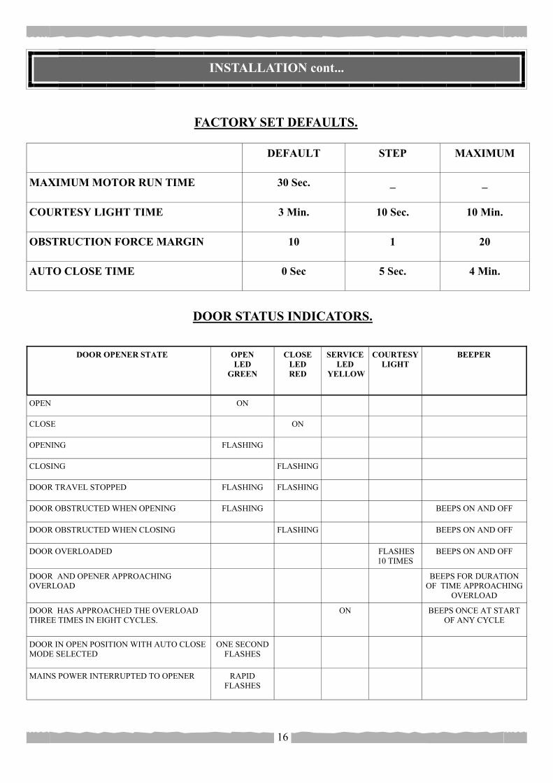
DEFAULT STEP MAXIMUM
MAXIMUM MOTOR RUN TIME 30 Sec. _ _
COURTESY LIGHT TIME 3 Min. 10 Sec. 10 Min.
OBSTRUCTION FORCE MARGIN 10 1 20
AUTO CLOSE TIME 0 Sec 5 Sec. 4 Min.
FACTORY SET DEFAULTS.
DOOR STATUS INDICATORS.
16
DOOR OPENER STATE OPEN LED
GREEN
CLOSE LED RED
SERVICE LED
YELLOW
COURTESY LIGHT
BEEPER
OPEN ON
CLOSE ON
OPENING FLASHING
CLOSING FLASHING
DOOR TRAVEL STOPPED FLASHING FLASHING
DOOR OBSTRUCTED WHEN OPENING FLASHING BEEPS ON AND OFF
DOOR OBSTRUCTED WHEN CLOSING FLASHING BEEPS ON AND OFF
DOOR OVERLOADED FLASHES 10 TIMES
BEEPS ON AND OFF
DOOR AND OPENER APPROACHING OVERLOAD
BEEPS FOR DURATION OF TIME APPROACHING
OVERLOAD
DOOR HAS APPROACHED THE OVERLOAD THREE TIMES IN EIGHT CYCLES.
ON BEEPS ONCE AT START OF ANY CYCLE
DOOR IN OPEN POSITION WITH AUTO CLOSE MODE SELECTED
ONE SECOND FLASHES
MAINS POWER INTERRUPTED TO OPENER RAPID FLASHES
INSTALLATION cont...
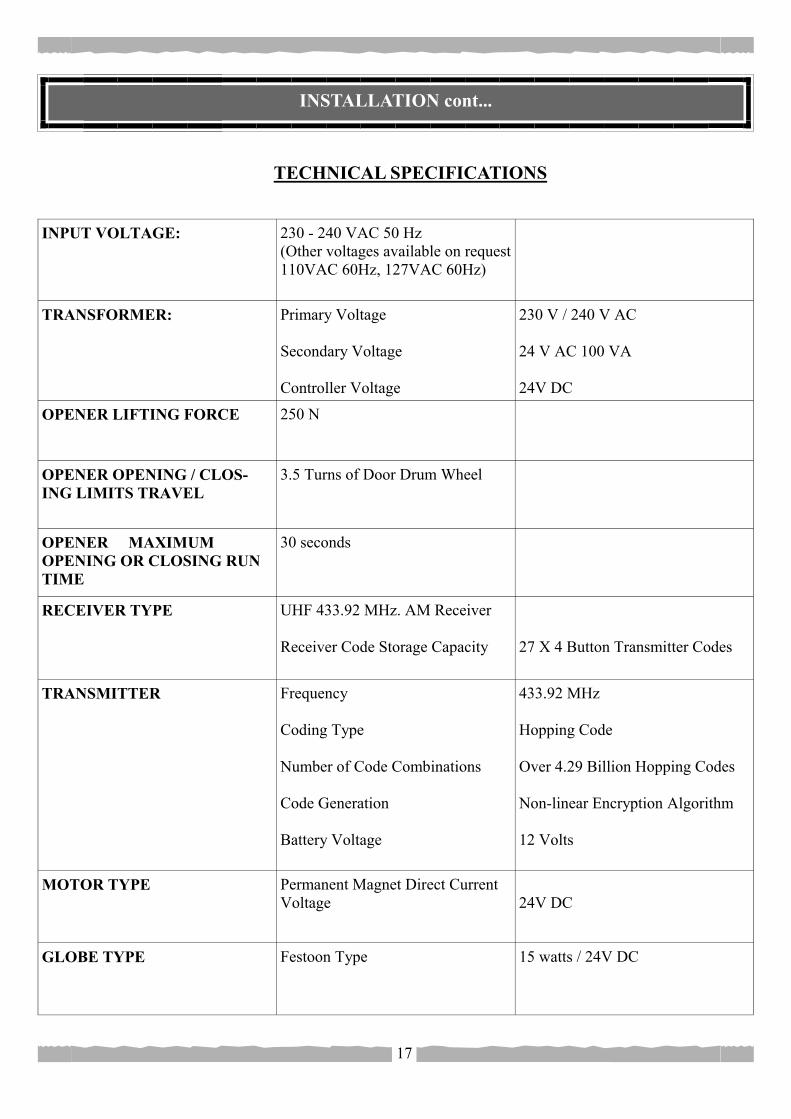
INPUT VOLTAGE: 230 - 240 VAC 50 Hz (Other voltages available on request 110VAC 60Hz, 127VAC 60Hz)
TRANSFORMER: Primary Voltage Secondary Voltage Controller Voltage
230 V / 240 V AC 24 V AC 100 VA 24V DC
OPENER LIFTING FORCE 250 N
OPENER OPENING / CLOS-ING LIMITS TRAVEL
3.5 Turns of Door Drum Wheel
OPENER MAXIMUM OPENING OR CLOSING RUN TIME
30 seconds
RECEIVER TYPE UHF 433.92 MHz. AM Receiver Receiver Code Storage Capacity
27 X 4 Button Transmitter Codes
TRANSMITTER Frequency Coding Type Number of Code Combinations Code Generation Battery Voltage
433.92 MHz Hopping Code Over 4.29 Billion Hopping Codes Non-linear Encryption Algorithm 12 Volts
MOTOR TYPE Permanent Magnet Direct Current Voltage
24V DC
GLOBE TYPE Festoon Type 15 watts / 24V DC
TECHNICAL SPECIFICATIONS
17
FAULTS AND REMEDIES
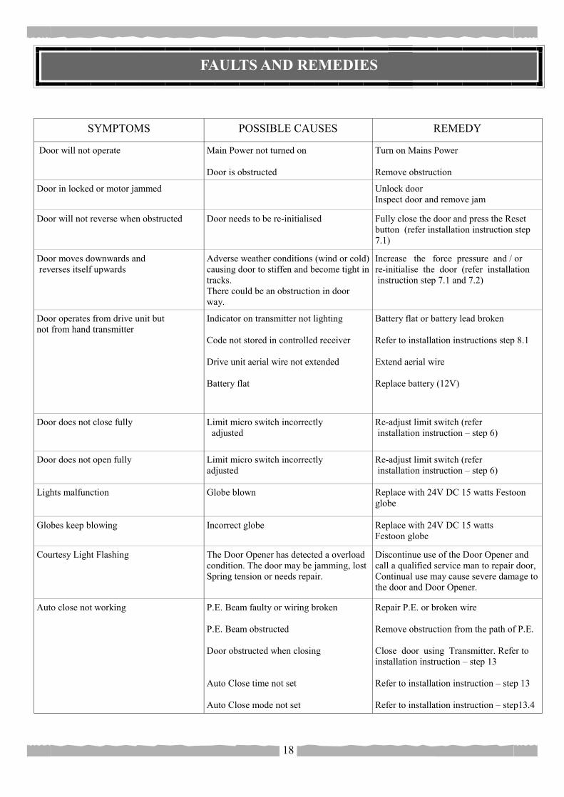
SYMPTOMS POSSIBLE CAUSES REMEDY
Door will not operate Main Power not turned on Door is obstructed
Turn on Mains Power Remove obstruction
Door in locked or motor jammed Unlock door Inspect door and remove jam
Door will not reverse when obstructed Door needs to be re-initialised
Fully close the door and press the Reset button (refer installation instruction step 7.1)
Door moves downwards and reverses itself upwards
Adverse weather conditions (wind or cold) causing door to stiffen and become tight in tracks. There could be an obstruction in door way.
Increase the force pressure and / or re-initialise the door (refer installation instruction step 7.1 and 7.2)
Door operates from drive unit but not from hand transmitter
Indicator on transmitter not lighting Code not stored in controlled receiver Drive unit aerial wire not extended Battery flat
Battery flat or battery lead broken Refer to installation instructions step 8.1 Extend aerial wire Replace battery (12V)
Door does not close fully Limit micro switch incorrectly adjusted
Re-adjust limit switch (refer installation instruction – step 6)
Door does not open fully Limit micro switch incorrectly adjusted
Re-adjust limit switch (refer installation instruction – step 6)
Lights malfunction
Globe blown Replace with 24V DC 15 watts Festoon globe
Globes keep blowing Incorrect globe Replace with 24V DC 15 watts Festoon globe
Courtesy Light Flashing The Door Opener has detected a overload condition. The door may be jamming, lost Spring tension or needs repair.
Discontinue use of the Door Opener and call a qualified service man to repair door, Continual use may cause severe damage to the door and Door Opener.
Auto close not working P.E. Beam faulty or wiring broken P.E. Beam obstructed Door obstructed when closing Auto Close time not set Auto Close mode not set
Repair P.E. or broken wire Remove obstruction from the path of P.E. Close door using Transmitter. Refer to installation instruction – step 13 Refer to installation instruction – step 13 Refer to installation instruction – step13.4
18
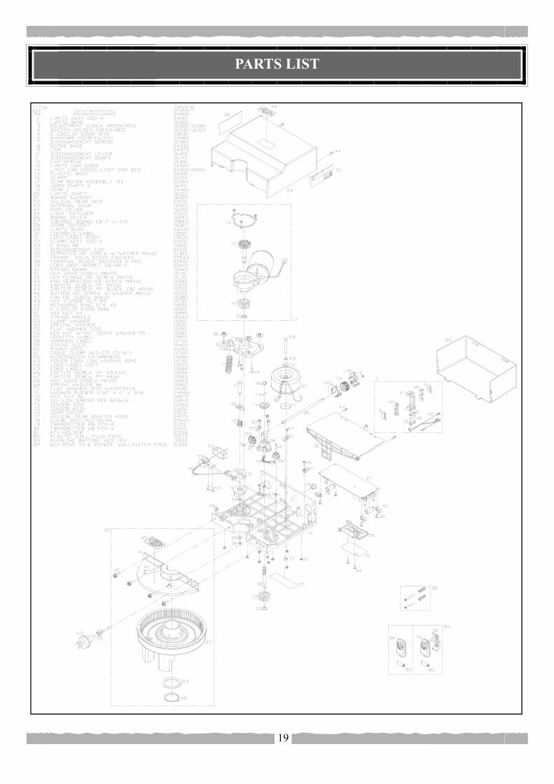
PARTS LIST
19

Subject to all of the matter set out below, Automatic Technology Australia Pty Ltd (“ATA”) WARRANTS for twenty four months from the date of purchase (specified in the receipt sales docket) that the Garage Door Opener System contained in the accompanying packaging (the “Product”) is free of any defects in material and workmanship rendering it unmerchantable. This warranty referred to above applied only where: a) the consumer seeking to rely on the said warranty; 1) returns the Product which it claims to be defective; and 2) presents the relevant sales docket and this warranty document, To the retailer from whom the Product was purchased to confirm that date of purchase; and b) the purchaser notified ATA or the retailer from whom the Product was purchased of the alleged defect in the Product immediately upon experience or learning of the alleged defect. Except for the warranty against defects in material and workmanship set out above, ATA gives no warranties of any kind whatsoever, whether express or implied or whether statutory or at common law, in relation to the Product, and all warranties of fitness for particular purpose and other warranties of whatsoever kind relating to the Product are hereby declaimed. Without limiting the generality of the foregoing, ATA disclaims any liability of whatsoever nature in respect of any claim or demand loss or damage which arise out of; a) accidental damage to or normal wear and tear to the Product or to the Product’s components; b) flood, fire or lighting; c) incorrect, improper or unreasonable maintenance and/or use; d) installation, adjustment or use other than ATA which is not in accordance with the instructions set out in installation instruction incorporated in the document; e) attempted or complete modification or repairs to the Product carried out by a person who is not authorised by ATA to carry out such modification or repairs; f) faulty or unsuitable wiring of structure to which the Product is fixed or connected; and g) radio (including citizen band transmission) or any electronic interference. h) blown fuses or damage caused by electrical surges. I) damage caused by insects. ATA’s liability under the warranty set out above is limited, at ATA’s absolute option, to replacing or repairing the Product which ATA, in its unfettered opinion, considers to the defective either in material and/or workmanship or to credit the consumer with the price at which the Product was purchased by the consumer. Where the Product is retailed by any person other than ATA, except for the warranty set out above, such person has no authority from ATA to give any warranty or guarantee on ATA’s behalf in addition to the warranty set out above.
**WARRANTY AND EXCLUSION OF LIABILITY**
AUTOMATIC TECHNOLOGY AUSTRALIA PTY LTD ABN 11 007 125 368
17-19 ADVANTAGE Rd, Highett, Victoria, Australia , 3190 Ph: 61 3 9532 2788 Fax: 61 3 9532 2799
E-mail: Support: [email protected] Sales: [email protected]
Printed for Export
20