Embed Size (px)
Citation preview
SurgeArrestersCatalog information
Eaton’s Cooper Power Systems catalogSurge arresters
Contents
Description Page
Improve system reliability with high cantilever strength and expanded overvoltage protection (B235-11026) . . . . . . . . . . . . . . . . . . . . . . . . . . . . . . . . . 3VariSTAR™ Type AZU heavy-duty distribution-class under-oil MOV surge arrester (TD235001EN) . . . . . . . . . . . . . . . . . . . . . . . . . . . . . . . . . . . . . . 5Secondary arresters and protective gaps (TD235002EN) . . . . . . . . . . . . . . . . . . . . . . . . . . . . 13VariSTAR™ Storm Trapper™ secondary class MOV surge arrester (TD235003EN) . . . . . . . . 21Storm Trapper™ H .E . (high energy) low-voltage distribution-class MOV surge arrester (TD235004EN) . . . . . . . . . . . . . . . . . . . . . . . . . . . . . . 29Arrester/flipper fuse combinations (TD235005EN) . . . . . . . . . . . . . . . . . . . . . . . . . . . . . . . . . 37UltraSIL™ polymer-housed VariSTAR™ IEEE® surge arresters; normal-duty (5 kA), heavyduty, and riser pole (10 kA) for MV systems to 36 kV (TD235006EN) . . . . . . . . 41VariSTAR™ Type AZL heavy-duty distribution-class MOV arrester (TD235007EN) . . . . . . . . . 57VariSTAR™ AZS normal-duty distribution-class MOV arrester (TD235008EN) . . . . . . . . . . . . 65VariSTAR Type AZE station-class surge arresters for systems through 345 kV IEEE certified (TD235009EN) . . . . . . . . . . . . . . . . . . . . . . . . . . . . . . . . . . . . . 73VariSTAR™ composite light-duty under-oil (CLU) MOV arrester (TD235010EN) . . . . . . . . . . . 89UltraSIL™ polymer-housed Evolution™ (10 kA) IEEE® surge arresters for MV systems to 36 kV (TD235011EN) . . . . . . . . . . . . . . . . . . . . . . . . . . . .101UltraSIL™ polymer-housed VariSTAR™ Type UI intermediate-class surge arresters (TD235012EN) . . . . . . . . . . . . . . . . . . . . . . . . . . . . . . . . .117UltraSIL™ polymer-housed VariSTAR™ station-class surge arresters (TD235013EN) . . . . . . 129UltraSIL™ polymer-housed VariSTAR™ UXL high-strength station-class surge arresters (TD235014EN) . . . . . . . . . . . . . . . . . . . . . . . . . . . . . . . . . . . . . 149
Surge arresters catalog contents
Technical Data Effective September 2014
Surge arresters catalog
www.cooperpower.com
Improve system reliability with high cantilever strength and expanded overvoltage protection
Optimal overvoltage protection
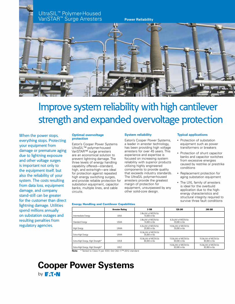
Eaton’s Cooper Power Systems UltraSIL™ polymer-housed VariSTAR™ surge arresters are an economical solution to prevent lightning damage. The three levels of energy handling capability offered—standard, high, and extra-high—are ideal for protection against repeated high energy switching surges, and provide reliable protection for substation equipment, capacitor banks, multiple lines, and cable circuits.
When the power stops, everything stops. Protecting your equipment from damage or premature aging due to lightning exposure and other voltage surges is important not only to the equipment itself, but also the reliability of your system. The costs resulting from data loss, equipment damage, and company stand-still can be greater for the customer than direct lightning damage. Utilities spend millions annually on substation outages and resulting penalties from regulatory agencies.
Arrester Rating 3-108 120-240 240-360
Intermediate Energy UIAA3.9kJ/kV of MCOV/Uc
10,000 in-lbs
Standard Energy USAA3.9kJ/kV of MCOV/Uc
14,000 in-lbs6.2kJ/kV of MCOV/Uc
20,000 in-lbs
High Energy UHAA6.2kJ/kV of MCOV/Uc
20,000 in-lbs10.0kJ/kV of MCOV/Uc
35,000 in-lbs
Extra-High Energy UXAA10.0kJ/kV of MCOV/Uc
35,000 in-lbs
Extra-High Energy, High Strength* UXLB15.0kJ/kV of MCOV/Uc
80,000 in-lbs15.0kJ/kV of MCOV/Uc
80,000 in-lbs15.0kJ/kV of MCOV/Uc
80,000 in-lbs
Extra-High Energy, High Strength* UXLC15.0kJ/kV of MCOV/Uc
92,000 in-lbs15.0kJ/kV of MCOV/Uc
92,000 in-lbs
otee:N * Tested to Class H per IEEE Std C62.11™-2012 standard
Energy Handling and Cantilever Capabilities
Typical applications
• Protection of substation equipment such as power transformers or breakers
• Protection of shunt capacitor banks and capacitor switches from excessive energies caused by restrike or prestrike conditions
• Replacement protection for aging substation equipment
• The UXL family of arresters is ideal for the overbuild application due to the high-energy characteristics and structural integrity required to survive three fault conditions
System reliability
Eaton’s Cooper Power Systems, a leader in arrester technology, has been providing high voltage arresters for over 45 years. This experience and expertise is focused on increasing system reliability with superior products utilizing highly engineered components to provide quality that exceeds industry standards. The UltraSIL polymer-housed arresters provide the greatest margin of protection for equipment, unsurpassed by any other solid-core design.
UltraSIL™ Polymer-Housed VariSTAR™ Surge Arresters Power Reliability
Eaton, Cooper Power Systems, and UltraSIL are valuable trademarks of Eaton in the U.S. and other countries. You are not permitted to use these trademarks without the prior written consent of Eaton.
IEEE Std C62.11™-2012 standard is a trademark of the Institute of Electrical and Electronics Engineers, Inc., (IEEE). This publication/product is not endorsed or approved by the IEEE.
All other trademarks are property of their respective owners.
Eaton1000 Eaton BoulevardCleveland, OH 44122United StatesEaton.com
Eaton’s Cooper Power Systems Business2300 Badger DriveWaukesha, WI 53188Cooperpower.com
© 2013 EatonAll Rights ReservedPrinted in USAPublication No. B235-11026November 2013
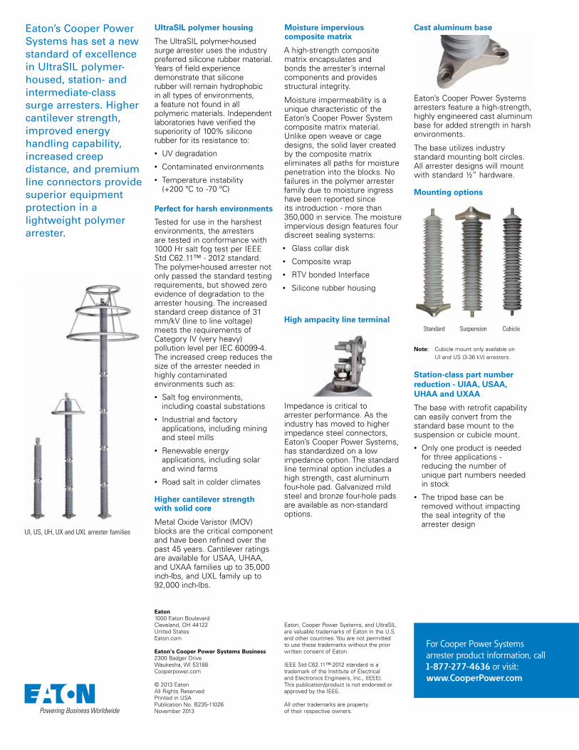
UI, US, UH, UX and UXL arrester families
Eaton’s Cooper Power Systems has set a new standard of excellence in UltraSIL polymer-housed, station- and intermediate-class surge arresters. Higher cantilever strength, improved energy handling capability, increased creep distance, and premium line connectors provide superior equipment protection in a lightweight polymer arrester.
Standard Suspension Cubicle
Mounting options
otee:N Cubicle mount only available on UI and US (3-36 kV) arresters.
For Cooper Power Systems arrester product information, call 1-877-277-4636 or visit:www.CooperPower.com
Cast aluminum base
Eaton’s Cooper Power Systems arresters feature a high-strength, highly engineered cast aluminum base for added strength in harsh environments.
The base utilizes industry standard mounting bolt circles. All arrester designs will mount with standard ½” hardware.
High ampacity line terminal
Impedance is critical to arrester performance. As the industry has moved to higher impedance steel connectors, Eaton’s Cooper Power Systems, has standardized on a low impedance option. The standard line terminal option includes a high strength, cast aluminum four-hole pad. Galvanized mild steel and bronze four-hole pads are available as non-standard options.
Station-class part number reduction - UIAA, USAA, UHAA and UXAA
The base with retrofit capability can easily convert from the standard base mount to the suspension or cubicle mount.
• Only one product is needed for three applications - reducing the number of unique part numbers needed in stock
• The tripod base can be removed without impacting the seal integrity of the arrester design
Moisture impervious composite matrix
A high-strength composite matrix encapsulates and bonds the arrester’s internal components and provides structural integrity.
Moisture impermeability is a unique characteristic of the Eaton’s Cooper Power System composite matrix material. Unlike open weave or cage designs, the solid layer created by the composite matrix eliminates all paths for moisture penetration into the blocks. No failures in the polymer arrester family due to moisture ingress have been reported since its introduction - more than 350,000 in service. The moisture impervious design features four discreet sealing systems:
• Glass collar disk
• Composite wrap
• RTV bonded Interface
• Silicone rubber housing
Higher cantilever strength with solid core
Metal Oxide Varistor (MOV) blocks are the critical component and have been refined over the past 45 years. Cantilever ratings are available for USAA, UHAA, and UXAA families up to 35,000 inch-lbs, and UXL family up to 92,000 inch-lbs.
UltraSIL polymer housing
The UltraSIL polymer-housed surge arrester uses the industry preferred silicone rubber material. Years of field experience demonstrate that silicone rubber will remain hydrophobic in all types of environments, a feature not found in all polymeric materials. Independent laboratories have verified the superiority of 100% silicone rubber for its resistance to:
• UV degradation
• Contaminated environments
• Temperature instability (+200 ºC to -70 ºC)
Perfect for harsh environments
Tested for use in the harshest environments, the arresters are tested in conformance with 1000 Hr salt fog test per IEEE Std C62.11™ - 2012 standard. The polymer-housed arrester not only passed the standard testing requirements, but showed zero evidence of degradation to the arrester housing. The increased standard creep distance of 31 mm/kV (line to line voltage) meets the requirements of Category IV (very heavy) pollution level per IEC 60099-4. The increased creep reduces the size of the arrester needed in highly contaminated environments such as:
• Salt fog environments, including coastal substations
• Industrial and factory applications, including mining and steel mills
• Renewable energy applications, including solar and wind farms
• Road salt in colder climates
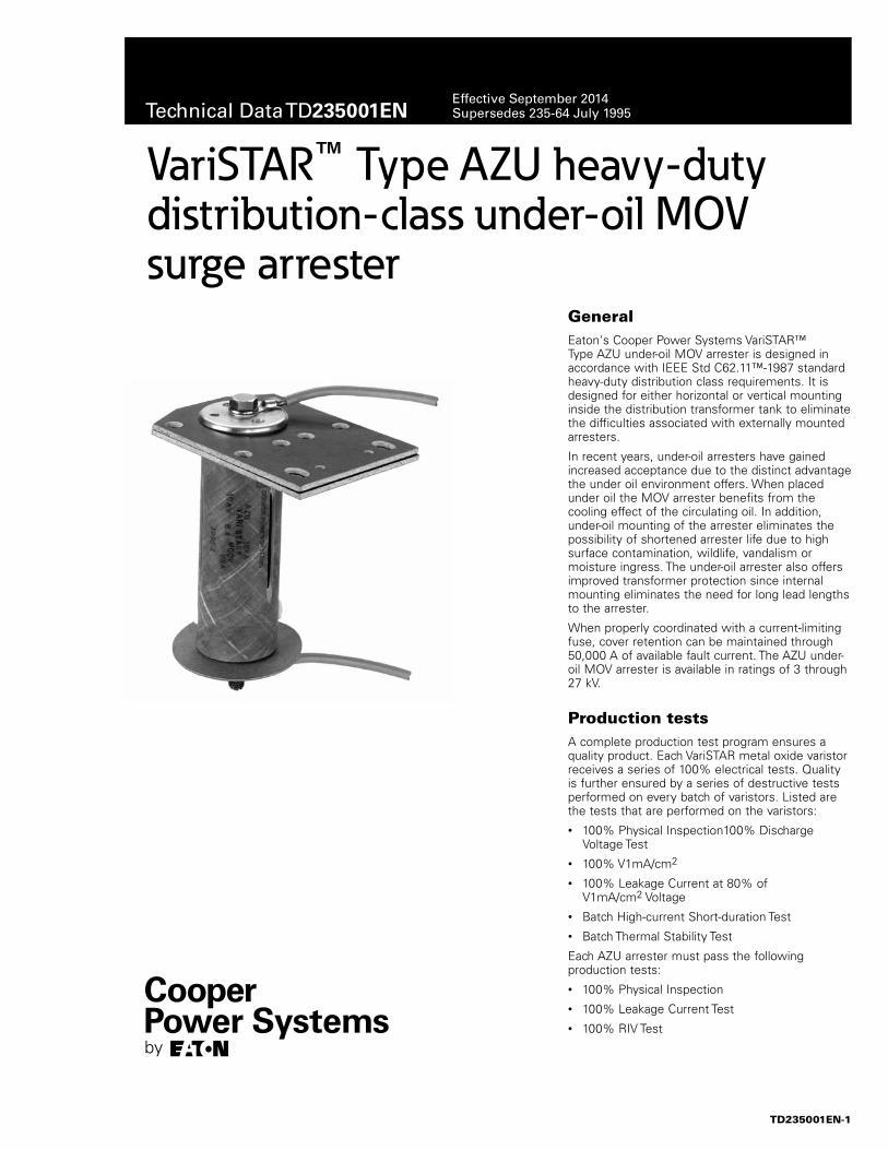
GeneralEaton's Cooper Power Systems VariSTAR™ Type AZU under-oil MOV arrester is designed in accordance with IEEE Std C62.11™-1987 standard heavy-duty distribution class requirements. It is designed for either horizontal or vertical mounting inside the distribution transformer tank to eliminate the difficulties associated with externally mounted arresters.
In recent years, under-oil arresters have gained increased acceptance due to the distinct advantage the under oil environment offers. When placed under oil the MOV arrester benefits from the cooling effect of the circulating oil. In addition, under-oil mounting of the arrester eliminates the possibility of shortened arrester life due to high surface contamination, wildlife, vandalism or moisture ingress. The under-oil arrester also offers improved transformer protection since internal mounting eliminates the need for long lead lengths to the arrester.
When properly coordinated with a current-limiting fuse, cover retention can be maintained through 50,000 A of available fault current. The AZU under-oil MOV arrester is available in ratings of 3 through 27 kV.
Production testsA complete production test program ensures a quality product. Each VariSTAR metal oxide varistor receives a series of 100% electrical tests. Quality is further ensured by a series of destructive tests performed on every batch of varistors. Listed are the tests that are performed on the varistors:• 100% Physical Inspection100% Discharge
Voltage Test• 100% V1mA/cm2
• 100% Leakage Current at 80% of V1mA/cm2 Voltage
• Batch High-current Short-duration Test• Batch Thermal Stability Test
Each AZU arrester must pass the following production tests:• 100% Physical Inspection• 100% Leakage Current Test• 100% RIV Test
VariSTAR™ Type AZU heavy-duty distribution-class under-oil MOV surge arrester
TD235001EN-1
Technical Data TD235001ENEffective September 2014Supersedes 235-64 July 1995
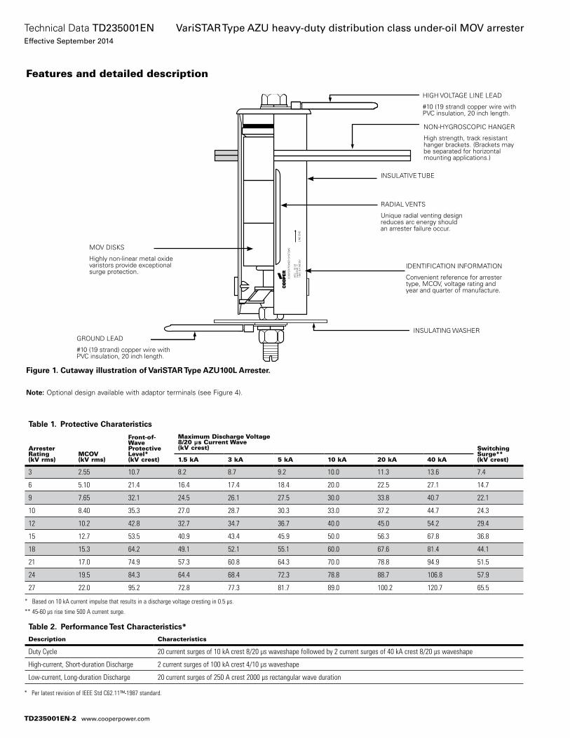
Features and detailed description
Figure 1. Cutaway illustration of VariSTAR Type AZU100L Arrester.
otee:N Optional design available with adaptor terminals (see Figure 4).
CO
OP
ER
PO
WE
R S
YS
TEM
S
AZU
1
0 kA
Var
iSTA
R10
kV 8
.4 M
CO
V
LIN
E E
ND
R
HIGH VOLTAGE LINE LEAD
#10 (19 strand) copper wire with PVC insulation, 20 inch length.
NON-HYGROSCOPIC HANGER
High strength, track resistant hanger brackets. (Brackets may be separated for horizontal mounting applications.)
INSULATIVE TUBE
RADIAL VENTS
Unique radial venting design reduces arc energy should an arrester failure occur.
IDENTIFICATION INFORMATION
Convenient reference for arrester type, MCOV, voltage rating and year and quarter of manufacture.
GROUND LEAD
#10 (19 strand) copper wire with PVC insulation, 20 inch length.
MOV DISKS
Highly non-linear metal oxide varistors provide exceptional surge protection.
INSULATING WASHER
Table 2. Performance Test Characteristics*
Description Characteristics
Duty Cycle 20 current surges of 10 kA crest 8/20 µs waveshape followed by 2 current surges of 40 kA crest 8/20 µs waveshape
High-current, Short-duration Discharge 2 current surges of 100 kA crest 4/10 µs waveshape
Low-current, Long-duration Discharge 20 current surges of 250 A crest 2000 µs rectangular wave duration
Table 1. Protective Charateristics
ArresterRating(kV rms)
MCOV(kV rms)
Front-of-WaveProtectiveLevel*(kV crest)
Maximum Discharge Voltage8/20 µs Current Wave(kV crest) Switching
Surge**(kV crest)1.5 kA 3 kA 5 kA 10 kA 20 kA 40 kA
3 2.55 10.7 8.2 8.7 9.2 10.0 11.3 13.6 7.4
6 5.10 21.4 16.4 17.4 18.4 20.0 22.5 27.1 14.7
9 7.65 32.1 24.5 26.1 27.5 30.0 33.8 40.7 22.1
10 8.40 35.3 27.0 28.7 30.3 33.0 37.2 44.7 24.3
12 10.2 42.8 32.7 34.7 36.7 40.0 45.0 54.2 29.4
15 12.7 53.5 40.9 43.4 45.9 50.0 56.3 67.8 36.8
18 15.3 64.2 49.1 52.1 55.1 60.0 67.6 81.4 44.1
21 17.0 74.9 57.3 60.8 64.3 70.0 78.8 94.9 51.5
24 19.5 84.3 64.4 68.4 72.3 78.8 88.7 106.8 57.9
27 22.0 95.2 72.8 77.3 81.7 89.0 100.2 120.7 65.5
* Based on 10 kA current impulse that results in a discharge voltage cresting in 0.5 μs.
** 45-60 μs rise time 500 A current surge.
* Per latest revision of IEEE Std C62.11™-1987 standard.
TD235001EN-2
Technical Data TD235001ENEffective September 2014
VariSTAR Type AZU heavy-duty distribution class under-oil MOV arrester
www.cooperpower.com
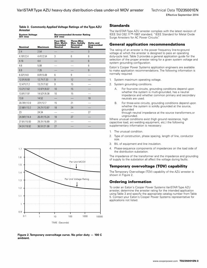
Figure 2. Temporary overvoltage curve. No prior duty — 100 C ambient.
TIME (Seconds)
10 100 10000.1
Per Unit MCOV
1
1.2
1.3
1.4
1.5
1.6
1.7
1.1
0.9
1 10000
Per Unit Voltage Rating
TIME (Seconds)
10 100 10000.1
Per Unit MCOV
1
1.2
1.3
1.4
1.5
1.6
1.7
1.1
0.9
1 10000
Per Unit Voltage Rating
Table 3. Commonly Applied Voltage Ratings of the Type AZU Arrester
System Voltage(kV rms)
Recommended Arrester Rating(kV rms)
Nominal Maximum
Four-WireWye; Multi-GroundedNeutral
Three-WireWye; SolidlyGroundedNeutral
Delta andUngroundedWye
2.4 2.54 — — 3
4.16Y/2.4 4.4Y/2.54 3 6 6
4.16 4.4 — — 6
4.8 5.08 — — 6
6.9 7.26 — — 9
8.32Y/4.8 8.8Y/5.08 6 9 —
12.0Y/6.93 12.7Y/7.33 9 12 —
12.47Y/7.2 13.2Y/7.62 9 15 —
13.2Y/7.62 13.97Y/8.07 10 15 —
13.8Y/7.97 14.52Y/8.38 10 15 —
13.8 14.52 — — 18
20.78Y/12.0 22Y/12.7 15 21 —
22.86Y/13.2 24.2Y/13.87 18 24 —
23 24.34 — — 27
24.94Y/14.4 26.4Y/15.24 18 27 —
27.6Y/15.93 29.3Y/16.89 21 — —
34.5Y/19.92 36.5Y/21.08 27 — —
StandardsThe VariSTAR Type AZU arrester complies with the latest revision of IEEE Std C62.11™-1987 standard, “IEEE Standard for Metal Oxide Surge Arresters for AC Power Circuits”.
General application recommendationsThe rating of an arrester is the power frequency line-to-ground voltage at which the arrester is designed to pass an operating duty-cycle test. Table 3 provides a general application guide for the selection of the proper arrester rating for a given system voltage and system grounding configuration.
Eaton's Cooper Power Systems application engineers are available to make application recommendations. The following information is normally required:
1. System maximum operating voltage.
2. System grounding conditions.
A. For four-wire circuits, grounding conditions depend upon whether the system is multi-grounded, has a neutral impedance and whether common primary and secondary neutrals are used.
B. For three-wire circuits, grounding conditions depend upon whether the system is solidly grounded at the source, grounded through neutral impedance at the source transformers,or ungrounded.
Where unusual conditions exist (high ground resistance, high capacitive load, arc-welding equipment, etc.) the following supplementary information is necessary:
1. The unusual condition.
2. Type of construction, phase spacing, length of line, conductor size.
3. BIL of equipment and line insulation.
4. Phase-sequence components of impedances on the load side of the distribution substation.
The impedance of the transformer and the impedance and grounding of supply to the substation all affect the voltage during faults.
Temporary overvoltage (TOV) capabilityThe Temporary Overvoltage (TOV) capability of the AZU arrester is shown in Figure 2.
Ordering informationTo order an Eaton's Cooper Power Systems VariSTAR Type AZU arrester, determine the arrester rating for the intended application using Table 3 and specify the appropriate catalog number from Table 5. Contact your Eaton's Cooper Power Systems representative for applications not listed.
TD235001EN-3
Technical Data TD235001ENEffective September 2014
VariSTAR Type AZU heavy-duty distribution-class under-oil MOV arrester
www.cooperpower.com
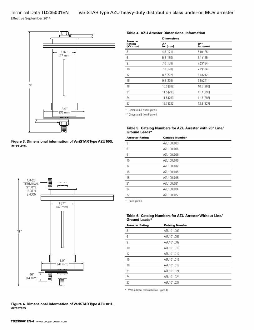
Figure 3. Dimensional information of VariSTAR Type AZU100L arresters.
Figure 4. Dimensional information of VariSTAR Type AZU101L arresters.
“B”
1.87” (47 mm)
3.0” (76 mm)
.56” (14 mm)
1/4-20 TERMINAL
STUDS (BOTH ENDS)
“A”
1.87” (47 mm)
3.0” (76 mm)
Table 5. Catalog Numbers for AZU Arrester with 20" Line/Ground Leads*
Arrester Rating Catalog Number
3 AZU100L003
6 AZU100L006
9 AZU100L009
10 AZU100L010
12 AZU100L012
15 AZU100L015
18 AZU100L018
21 AZU100L021
24 AZU100L024
27 AZU100L027
Table 6. Catalog Numbers for AZU Arrester Without Line/Ground Leads*
Arrester Rating Catalog Number
3 AZU101L003
6 AZU101L006
9 AZU101L009
10 AZU101L010
12 AZU101L012
15 AZU101L015
18 AZU101L018
21 AZU101L021
24 AZU101L024
27 AZU101L027
Table 4. AZU Arrester Dimensional Information
ArresterRating(kV rms)
Dimensions
A*in. (mm)
B**in. (mm)
3 4.8 (121) 5.0 (126)
6 5.9 (150) 6.1 (155)
9 7.0 (178) 7.2 (184)
10 7.0 (178) 7.2 (184)
12 8.2 (207) 8.4 (212)
15 9.3 (236) 9.5 (241)
18 10.3 (262) 10.5 (266)
21 11.5 (293) 11.7 (298)
24 11.5 (293) 11.7 (298)
27 12.7 (322) 12.9 (327)
* Dimension A from Figure 3.
** Dimension B from Figure 4.
* See Figure 3.
* With adapter terminals (see Figure 4).
TD235001EN-4
Technical Data TD235001ENEffective September 2014
VariSTAR Type AZU heavy-duty distribution class under-oil MOV arrester
www.cooperpower.com
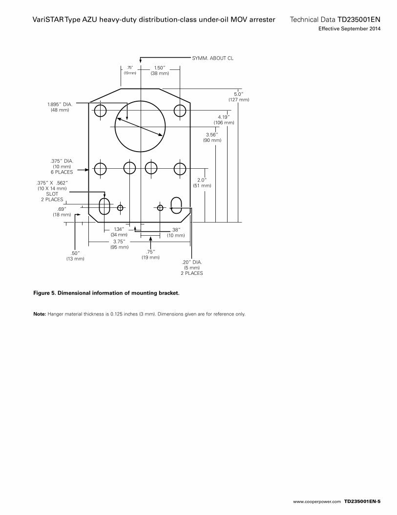
Figure 5. Dimensional information of mounting bracket.
otee:N Hanger material thickness is 0.125 inches (3 mm). Dimensions given are for reference only.
1.50” (38 mm)
5.0” (127 mm)
SYMM. ABOUT CL
4.19” (106 mm)
3.56” (90 mm)
2.0” (51 mm)
.75” (19 mm)
1.895” DIA. (48 mm)
.375” DIA. (10 mm)
6 PLACES
.75” (19 mm)
.38” (10 mm)
.20” DIA. (5 mm)
2 PLACES
1.34” (34 mm)
3.75” (95 mm)
.375” X .562” (10 X 14 mm)
SLOT 2 PLACES
.69” (18 mm)
.50” (13 mm)
TD235001EN-5
Technical Data TD235001ENEffective September 2014
VariSTAR Type AZU heavy-duty distribution-class under-oil MOV arrester
www.cooperpower.com
This page is intentionally left blank.
TD235001EN-6
Technical Data TD235001ENEffective September 2014
VariSTAR Type AZU heavy-duty distribution class under-oil MOV arrester
www.cooperpower.com
This page is intentionally left blank.
TD235001EN-7
Technical Data TD235001ENEffective September 2014
VariSTAR Type AZU heavy-duty distribution-class under-oil MOV arrester
www.cooperpower.com
Eaton, Cooper Power Systems, and VariSTAR are valuable trademarks of Eaton in the U.S. and other countries. You are not permitted to use the these trademarks without the prior written consent of Eaton.IEEE Std C62.11™-1987 standard is a trademark of the Institute of Electrical and Electronics Engineers, Inc., (IEEE). This pub-lication is not endorsed or approved by the IEEE.
VariSTAR Type AZU heavy-duty distribution-class under-oil MOV arrester
Eaton1000 Eaton BoulevardCleveland, OH 44122United StatesEaton.com
Eaton’s Cooper Power Systems Business2300 Badger DriveWaukesha, WI 53188United StatesCooperpower.com
© 2014 EatonAll Rights ReservedPrinted in USAPublication No. TD235001EN
Technical Data TD235001ENEffective September 2014
For Eaton’s Cooper Power Systems VariSTAR surge arrester product information call 1-877-277-4636 or visit: www.cooperpower.com.
TD235001EN-8
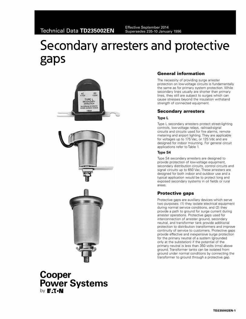
General information The necessity of providing surge arrester protection on low-voltage circuits is fundamentally the same as for primary system protection. While secondary lines usually are shorter than primary lines, they still are subject to surges which can cause stresses beyond the insulation withstand strength of connected equipment.
Secondary arrestersType L
Type L secondary arresters protect street-lighting controls, low-voltage relays, railroad-signal circuits and circuits used for fire alarms, remote metering and airport lighting. They are applicable for voltages up to 175 Vac, or 125 Vdc and are designed for indoor mounting. For general circuit applications refer to Table 1.
Type S4
Type S4 secondary arresters are designed to provide protection of low-voltage equipment, secondary distribution circuits, control circuits and signal circuits up to 650 Vac. These arresters are designed for both indoor and outdoor use and a typical application would be to protect long and exposed secondary systems in oil fields or rural areas.
Protective gaps Protective gaps are auxiliary devices which serve two purposes: (1) they isolate electrical equipment during normal service conditions, and (2) they provide a path to ground for surge current during arrester operations. Protective gaps used for interconnection of arrester ground, secondary neutral, and transformer tank provide additional protection to distribution transformers and improve continuity of service to customers. Protective gaps provide effective and inexpensive surge protection for the primary neutral of a system (grounded only at the substation) if the potential of the primary neutral is less than 350 volts (rms) above ground. Transformer tanks can be isolated from ground under normal conditions by connecting the transformer to ground through a protective gap.
Secondary arresters and protective gaps
TD235002EN-1
Technical Data TD235002ENEffective September 2014Supersedes 235-10 January 1996
Features and detailed description
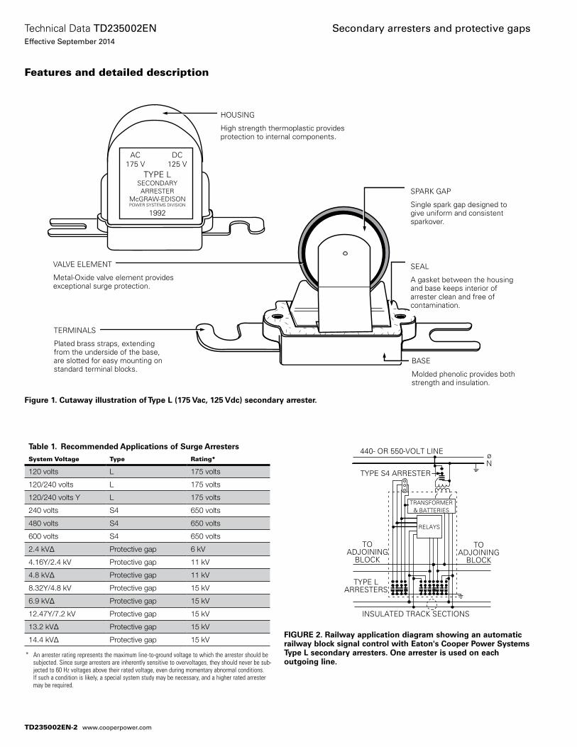
Figure 1. Cutaway illustration of Type L (175 Vac, 125 Vdc) secondary arrester.
AC175 V
DC125 V
TYPE LSECONDARYARRESTER
McGRAW-EDISONPOWER SYSTEMS DIVISION
1992
VALVE ELEMENT
Metal-Oxide valve element provides exceptional surge protection.
TERMINALS
Plated brass straps, extending from the underside of the base, are slotted for easy mounting on standard terminal blocks.
SPARK GAP
Single spark gap designed to give uniform and consistent sparkover.
HOUSING
High strength thermoplastic provides protection to internal components.
SEAL
A gasket between the housing and base keeps interior of arrester clean and free of contamination.
BASE
Molded phenolic provides both strength and insulation.
Table 1. Recommended Applications of Surge Arresters
System Voltage Type Rating*
120 volts L 175 volts
120/240 volts L 175 volts
120/240 volts Y L 175 volts
240 volts S4 650 volts
480 volts S4 650 volts
600 volts S4 650 volts
2.4 kV∆ Protective gap 6 kV
4.16Y/2.4 kV Protective gap 11 kV
4.8 kV∆ Protective gap 11 kV
8.32Y/4.8 kV Protective gap 15 kV
6.9 kV∆ Protective gap 15 kV
12.47Y/7.2 kV Protective gap 15 kV
13.2 kV∆ Protective gap 15 kV
14.4 kV∆ Protective gap 15 kV
* An arrester rating represents the maximum line-to-ground voltage to which the arrester should be subjected. Since surge arresters are inherently sensitive to overvoltages, they should never be sub-jected to 60 Hz voltages above their rated voltage, even during momentary abnormal conditions. If such a condition is likely, a special system study may be necessary, and a higher rated arrester may be required.
FIGURE 2. Railway application diagram showing an automatic railway block signal control with Eaton's Cooper Power Systems Type L secondary arresters. One arrester is used on each outgoing line.
TYPE S4 ARRESTER
440- OR 550-VOLT LINE øN
TRANSFORMER& BATTERIES
RELAYS
TOADJOINING
BLOCK
INSULATED TRACK SECTIONS
TYPE LARRESTERS
TOADJOINING
BLOCK
TD235002EN-2
Technical Data TD235002ENEffective September 2014
Secondary arresters and protective gaps
www.cooperpower.com
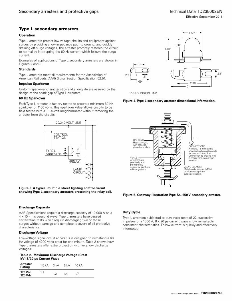
Type L secondary arrestersOperation
Type L arresters protect low-voltage circuits and equipment against surges by providing a low-impedance path to ground, and quickly draining off surge voltages. The arrester promptly restores the circuit to normal by interrupting the 60 Hz current which follows the surge current.
Examples of applications of Type L secondary arresters are shown in Figures 2 and 3.
Standards
Type L arresters meet all requirements for the Association of American Railroads (AAR) Signal Section Specification 52.51.
Impulse Sparkover
Uniform sparkover characteristics and a long life are assured by the design of the spark gap of Type L arresters.
60 Hz Sparkover
Each Type L arrester is factory tested to assure a minimum 60 Hz sparkover of 1100 volts. This sparkover value allows circuits to be field tested with a 1000-volt megohmmeter without removing the arrester from the circuits.
Discharge Capacity
AAR Specifications require a discharge capacity of 10,000 A on a 4 x 10 - microsecond wave. Type L arresters have passed certification tests which require discharging two of these surges without damage and complete recovery of all protective characteristics.
Discharge Voltage
Low-voltage signal circuit apparatus is designed to withstand a 60 Hz voltage of 4200 volts crest for one minute. Table 2 shows how Type L arresters offer extra protection with very low discharge voltages.
Duty Cycle
Type L arresters subjected to duty-cycle tests of 22 successive impulses of a 1500 A, 8 x 20 µs current wave show remarkably consistent characteristics. Follow current is quickly and effectively interrupted.
Figure 4. Type L secondary arrester dimensional information.
1"
.5"
1.69"3"
2.38"
.63".25"
1.81"1.88"
1.56"
1" GROUNDING LINK
Figure 5. Cutaway illustration Type S4, 650 V secondary arrester.
HOUSINGHigh-strength, wet-process, glazed porcelain.
SEALSArresters are positively and permanently sealed by syntheticrubber gaskets.
VALVE ELEMENTMetal oxide varistor (MOV)provides exceptionalsurge protection.
CONNECTIONSFlexilble, 18-inch lead is provided with most models for connection to line. Connection to ground lead is made with clamp-type terminal.
Table 2. Maximum Discharge Voltage (Crest kV) 8/20 μs Current Wave
ArresterRating 1.5 kA 3 kA 5 kA 10 kA
175 Vac125 Vdc
1.1 1.2 1.4 1.7
Figure 3. A typical multiple street lighting control circuit showing Type L secondary arresters protecting the relay coil.
120/240 VOLT LINE
CONTROLSTATION
TYPE LARRESTER
(RELAY)
LAMPCIRCUIT
TD235002EN-3
Technical Data TD235002ENEffective September 2015
Secondary arresters and protective gaps
www.cooperpower.com
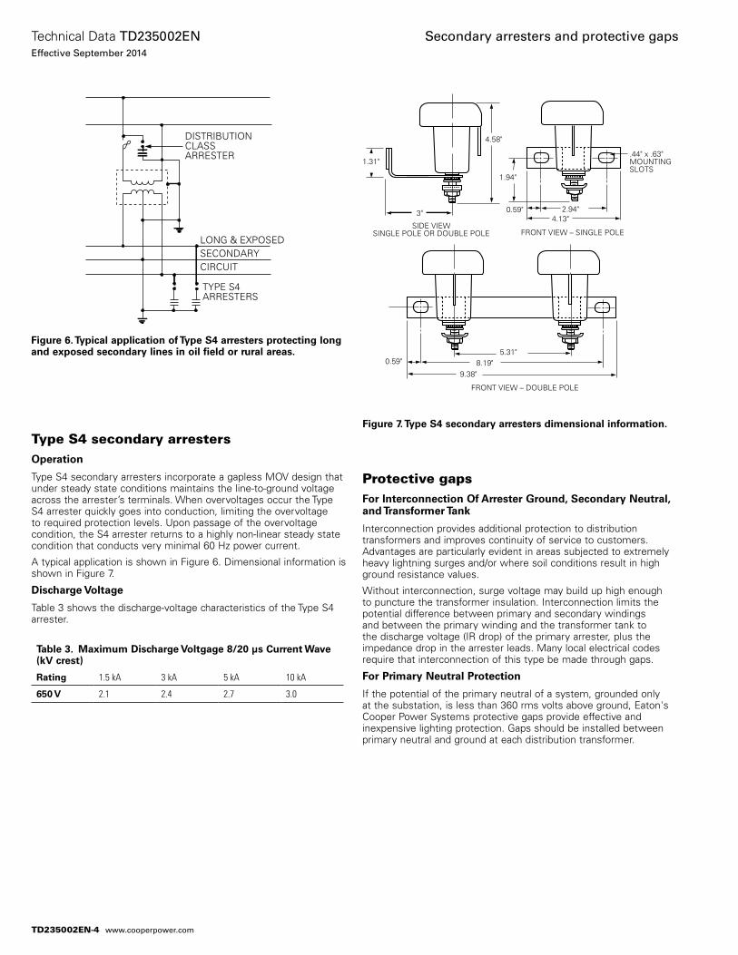
Type S4 secondary arrestersOperation
Type S4 secondary arresters incorporate a gapless MOV design that under steady state conditions maintains the line-to-ground voltage across the arrester’s terminals. When overvoltages occur the Type S4 arrester quickly goes into conduction, limiting the overvoltage to required protection levels. Upon passage of the overvoltage condition, the S4 arrester returns to a highly non-linear steady state condition that conducts very minimal 60 Hz power current.
A typical application is shown in Figure 6. Dimensional information is shown in Figure 7.
Discharge Voltage
Table 3 shows the discharge-voltage characteristics of the Type S4 arrester.
Protective gapsFor Interconnection Of Arrester Ground, Secondary Neutral, and Transformer Tank
Interconnection provides additional protection to distribution transformers and improves continuity of service to customers. Advantages are particularly evident in areas subjected to extremely heavy lightning surges and/or where soil conditions result in high ground resistance values.
Without interconnection, surge voltage may build up high enough to puncture the transformer insulation. Interconnection limits the potential difference between primary and secondary windings and between the primary winding and the transformer tank to the discharge voltage (IR drop) of the primary arrester, plus the impedance drop in the arrester leads. Many local electrical codes require that interconnection of this type be made through gaps.
For Primary Neutral Protection
If the potential of the primary neutral of a system, grounded only at the substation, is less than 360 rms volts above ground, Eaton's Cooper Power Systems protective gaps provide effective and inexpensive lighting protection. Gaps should be installed between primary neutral and ground at each distribution transformer.
Figure 6. Typical application of Type S4 arresters protecting long and exposed secondary lines in oil field or rural areas.
DISTRIBUTION CLASSARRESTER
LONG & EXPOSEDSECONDARYCIRCUIT
TYPE S4ARRESTERS
Figure 7. Type S4 secondary arresters dimensional information.
3"
1.31"
1.94"
4.58"
.44" x .63"MOUNTINGSLOTS
0.59"
0.59"
2.94"4.13"
9.38"8.19"
5.31"
FRONT VIEW – SINGLE POLESIDE VIEW
SINGLE POLE OR DOUBLE POLE
FRONT VIEW – DOUBLE POLE
Table 3. Maximum Discharge Voltgage 8/20 μs Current Wave (kV crest)
Rating 1.5 kA 3 kA 5 kA 10 kA
650 V 2.1 2.4 2.7 3.0
TD235002EN-4
Technical Data TD235002ENEffective September 2014
Secondary arresters and protective gaps
www.cooperpower.com
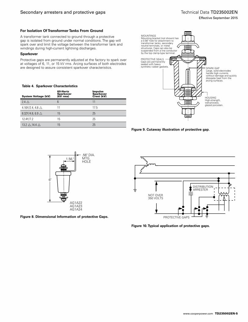
For Isolation Of Transformer Tanks From Ground
A transformer tank connected to ground through a protective gap is isolated from ground under normal conditions. The gap will spark over and limit the voltage between the transformer tank and windings during high-current lightning discharges.
Sparkover
Protective gaps are permanently adjusted at the factory to spark over at voltages of 6, 11, or 15 kV rms. Arcing surfaces of both electrodes are designed to assure consistent sparkover characteristics.
Figure 9. Cutaway illustration of protective gap.
SPARK GAPLarge, solid electrodes handle high currents without damage and quicklydissipate heat from the arcing surfaces.
PROTECTIVE SEALSGaps are permanently sealed with heavy synthetic rubber gaskets.
HOUSINGHigh-strength, wet-process, glazed porcelain.
MOUNTINGSMounting bracket (not shown) has a 0.56" hole for attachment to transformer tanks, secondary neutral terminals, or metal structures. Caps can also be suspended from a line conductor by the top clamp-type terminal.
Figure 8. Dimensional Information of protective Gaps.
6"
AG1A22AG1A23AG1A24
.56" DIA. MTG. HOLE
1.56 "
Figure 10. Typical application of protective gaps.
NOT OVER350 VOLTS
PROTECTIVE GAPS
DISTRIBUTIONARRESTER
Table 4. Sparkover Characteristics
System Voltage (kV)
60-HertzSparkover(kV rms)
ImpulseSparkoverCrest (kV)
2.4 6 11
4.16Y/2.4, 4.8 11 17.5
8.32Y/4.8, 6.9 15 25
12.4Y/7.2 15 25
13.2 ,14.4 15 25
TD235002EN-5
Technical Data TD235002ENEffective September 2015
Secondary arresters and protective gaps
www.cooperpower.com
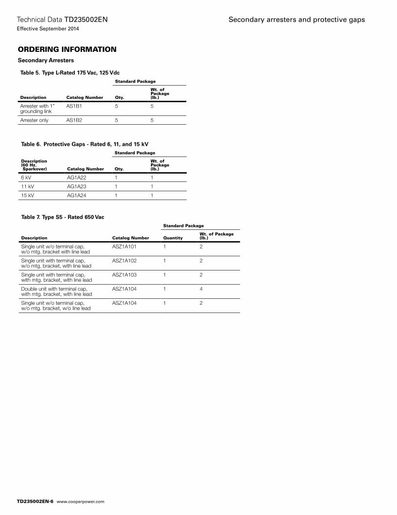
ORDERING INFORMATIONSecondary Arresters
Table 7. Type S5 - Rated 650 Vac
Description Catalog Number
Standard Package
QuantityWt. of Package (lb.)
Single unit w/o terminal cap,w/o mtg. bracket with line lead
ASZ1A101 1 2
Single unit with terminal cap,w/o mtg. bracket, with line lead
ASZ1A102 1 2
Single unit with terminal cap,with mtg. bracket, with line lead
ASZ1A103 1 2
Double unit with terminal cap,with mtg. bracket, with line lead
ASZ1A104 1 4
Single unit w/o terminal cap,w/o mtg. bracket, w/o line lead
ASZ1A104 1 2
Table 5. Type L-Rated 175 Vac, 125 Vdc
Description Catalog Number
Standard Package
Qty.
Wt. of Package(lb.)
Arrester with 1”grounding link
AS1B1 5 5
Arrester only AS1B2 5 5
Table 6. Protective Gaps - Rated 6, 11, and 15 kV
Description(60 Hz. Sparkover) Catalog Number
Standard Package
Qty.
Wt. ofPackage(lb.)
6 kV AG1A22 1 1
11 kV AG1A23 1 1
15 kV AG1A24 1 1
TD235002EN-6
Technical Data TD235002ENEffective September 2014
Secondary arresters and protective gaps
www.cooperpower.com

TD235002EN-7
Technical Data TD235002ENEffective September 2015
Secondary arresters and protective gaps
www.cooperpower.com
Eaton and Cooper Power Systems are valu-able trademarks of Eaton in the U.S. and other countries. You are not permitted to use the these trademarks without the prior written consent of Eaton.
Secondary arresters and protective gaps
Eaton1000 Eaton BoulevardCleveland, OH 44122United StatesEaton.com
Eaton’s Cooper Power Systems Business2300 Badger DriveWaukesha, WI 53188United StatesCooperpower.com
© 2014 EatonAll Rights ReservedPrinted in USAPublication No. TD235002EN
Technical Data TD235002ENEffective September 2014
For Eaton’s Cooper Power Systems secondary arresters and protective gaps product information call 1-877-277-4636 or visit: www.cooperpower.com.
TD235002EN-8
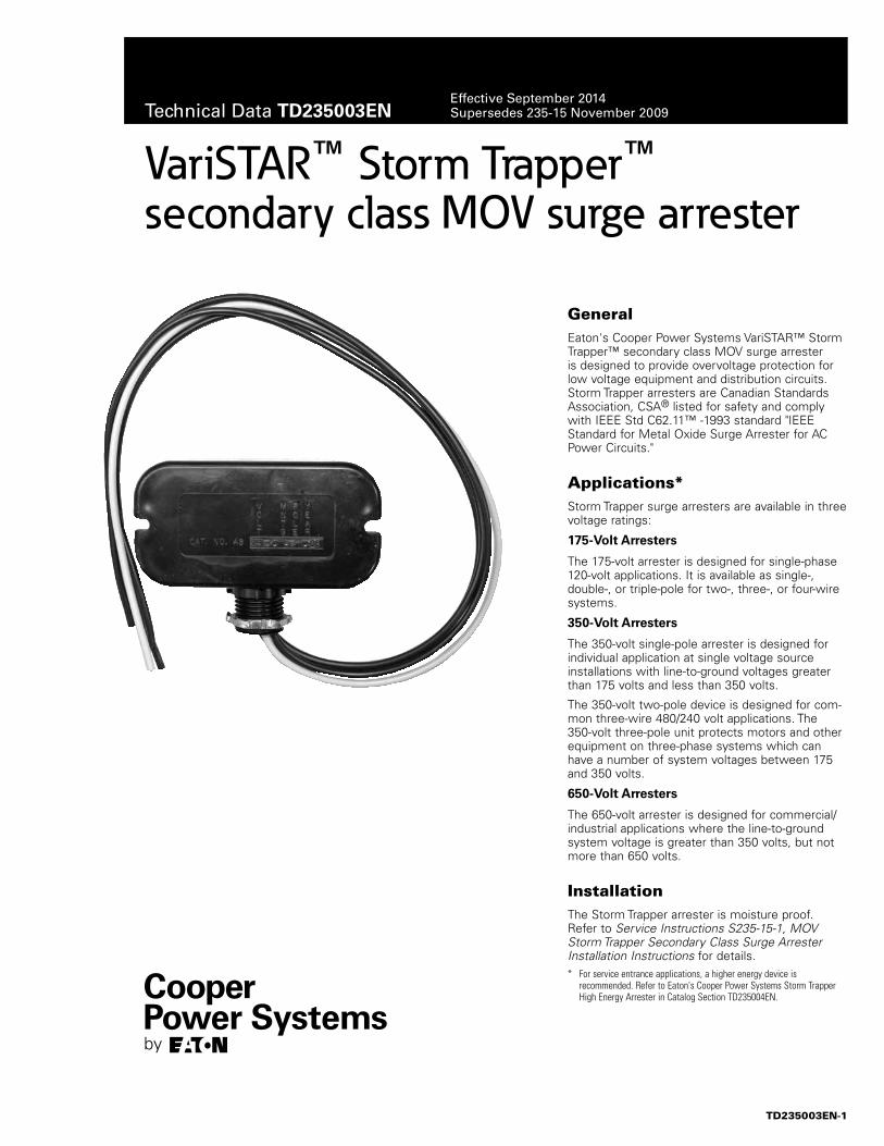
VariSTAR™ Storm Trapper™secondary class MOV surge arrester
GeneralEaton's Cooper Power Systems VariSTAR™ Storm Trapper™ secondary class MOV surge arrester is de signed to provide overvoltage pro tec tion for low voltage equipment and dis tri bu tion circuits. Storm Trapper ar rest ers are Canadian Standards Association, CSA® listed for safety and comply with IEEE Std C62.11™ -1993 standard "IEEE Standard for Metal Oxide Surge Arrester for AC Power Circuits."
Applications*Storm Trapper surge arresters are avail able in three volt age ratings:
175-Volt Arresters
The 175-volt arrester is de signed for single-phase 120-volt ap pli ca tions. It is available as single-, double-, or triple-pole for two-, three-, or four-wire systems.
350-Volt Arresters
The 350-volt single-pole arrester is de signed for in di vid u al application at sin gle voltage source in stal la tions with line-to-ground voltages greater than 175 volts and less than 350 volts.
The 350-volt two-pole device is designed for com-mon three-wire 480/240 volt applications. The 350-volt three-pole unit pro tects motors and other equipment on three-phase systems which can have a number of sys tem voltages be tween 175 and 350 volts.
650-Volt Arresters
The 650-volt arrester is designed for com mer cial/industrial ap pli ca tions where the line-to-ground system voltage is great er than 350 volts, but not more than 650 volts.
InstallationThe Storm Trapper arrester is mois ture proof. Refer to Service Instructions S235-15-1, MOV Storm Trapper Secondary Class Surge Arrester Installation Instructions for details.* For service entrance applications, a higher energy device is
recommended. Refer to Eaton's Cooper Power Systems Storm Trapper High Energy Arrester in Catalog Section TD235004EN.
TD235003EN-1
Technical Data TD235003ENEffective September 2014Supersedes 235-15 November 2009
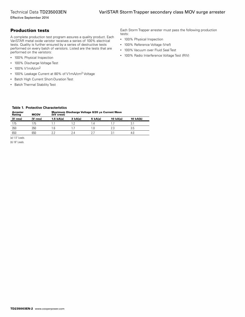
Each Storm Trapper arrester must pass the following production tests:• 100% Physical Inspection• 100% Reference Voltage (Vref)• 100% Vacuum over Fluid Seal Test• 100% Radio Interference Voltage Test (RIV)
Production testsA complete production test program assures a quality product. Each VariSTAR metal oxide varistor receives a series of 100% electrical tests. Quality is further ensured by a series of destructive tests performed on every batch of varistors. Listed are the tests that are performed on the varistors:• 100% Physical In spec tion• 100% Discharge Voltage Test• 100% V1mA/cm2
• 100% Leakage Current at 80% of V1mA/cm2 Voltage• Batch High Current Short-Duration Test• Batch Thermal Stability Test
(a) 1.5" Leads.
(b) 18" Leads.
Table 1. Protective CharacteristicsArrester Rating MCOV
Maximum Discharge Voltage 8/20 µs Current Wave(kV crest)
(V rms) (V rms) 1.5 kA(a) 3 kA(a) 5 kA(a) 10 kA(a) 10 kA(b)
175 175 1.1 1.2 1.4 1.7 3.1350 350 1.6 1.7 1.0 2.3 3.5650 650 2.2 2.4 2.7 3.1 4.0
TD235003EN-2
Technical Data TD235003ENEffective September 2014
VariSTAR Storm Trapper secondary class MOV surge arrester
www.cooperpower.com
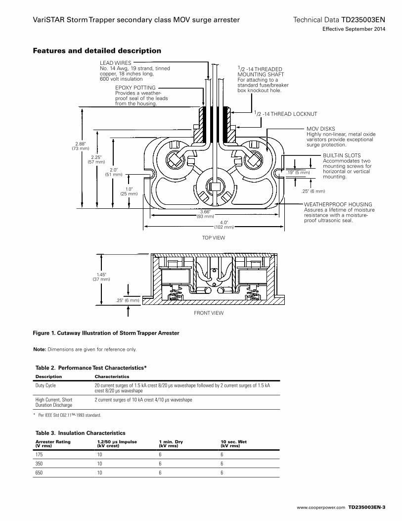
Table 2. Performance Test Characteristics*
Description Characteristics
Duty Cycle 20 current surges of 1.5 kA crest 8/20 µs waveshape followed by 2 current surges of 1.5 kA crest 8/20 µs waveshape
High Current, Short Duration Discharge
2 current surges of 10 kA crest 4/10 µs waveshape
Features and detailed description
Table 3. Insulation Characteristics
Arrester Rating (V rms)
1.2/50 µs Impulse (kV crest)
1 min. Dry (kV rms)
10 sec. Wet (kV rms)
175 10 6 6
350 10 6 6
650 10 6 6
Figure 1. Cutaway Illustration of Storm Trapper Arrester
otee:N Dimensions are given for reference only.
2.88"(73 mm)
1.0"(25 mm)
2.25"(57 mm)
LEAD WIRESNo. 14 Awg, 19 strand, tinnedcopper, 18 inches long,600 volt insulation
EPOXY POTTING Provides a weather-proof seal of the leads from the housing.
2.0"(51 mm) .19" (5 mm)
3.66"(93 mm)
BUILT-IN SLOTSAccommodates two mounting screws for horizontal or vertical mounting.
MOV DISKSHighly non-linear, metal oxidevaristors provide exceptionalsurge protection.
TOP VIEW
FRONT VIEW
1.45"(37 mm)
.25" (6 mm)
4.0"(102 mm)
WEATHERPROOF HOUSINGAssures a lifetime of moistureresistance with a moisture-proof ultrasonic seal.
.25" (6 mm)
1/2 -14 THREADEDMOUNTING SHAFTFor attaching to a standard fuse/breaker box knockout hole.
1/2 -14 THREAD LOCKNUT
* Per IEEE Std C62.11™-1993 standard.
TD235003EN-3
Technical Data TD235003ENEffective September 2014
VariSTAR Storm Trapper secondary class MOV surge arrester
www.cooperpower.com
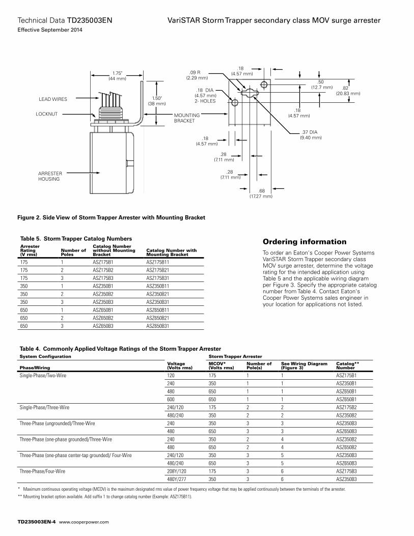
Table 4. Commonly Applied Voltage Ratings of the Storm Trapper ArresterSystem Configuration
Voltage(Volts rms)
Storm Trapper Arrester
Phase/WiringMCOV*(Volts rms)
Number of Pole(s)
See Wiring Diagram(Figure 3)
Catalog**Number
Single-Phase/Two-Wire 120 175 1 1 ASZ175B1240 350 1 1 ASZ350B1480 650 1 1 ASZ650B1600 650 1 1 ASZ650B1
Single-Phase/Three-Wire 240/120 175 2 2 ASZ175B2480/240 350 2 2 ASZ350B2
Three-Phase (ungrounded)/Three-Wire 240 350 3 3 ASZ350B3480 650 3 3 ASZ650B3
Three-Phase (one-phase grounded)/Three-Wire 240 350 2 4 ASZ350B2480 650 2 4 ASZ650B2
Three-Phase (one-phase center-tap grounded)/ Four-Wire 240/120 350 3 5 ASZ350B3480/240 650 3 5 ASZ650B3
Three-Phase/Four-Wire 208Y/120 175 3 6 ASZ175B3480Y/277 350 3 6 ASZ350B3
Table 5. Storm Trapper Catalog NumbersArrester Rating(V rms)
Number of Poles
Catalog Number without Mounting Bracket
Catalog Number with Mounting Bracket
175 1 ASZ175B1 ASZ175B11175 2 ASZ175B2 ASZ175B21175 3 ASZ175B3 ASZ175B31350 1 ASZ350B1 ASZ350B11350 2 ASZ350B2 ASZ350B21350 3 ASZ350B3 ASZ350B31650 1 ASZ650B1 ASZ650B11650 2 ASZ650B2 ASZ650B21650 3 ASZ650B3 ASZ650B31
Figure 2. Side View of Storm Trapper Arrester with Mounting Bracket
1.50"(38 mm)
1.75"(44 mm)
LEAD WIRES
ARRESTERHOUSING
Ordering informationTo order an Eaton's Cooper Power Systems VariSTAR Storm Trapper secondary class MOV surge arrester, determine the voltage rating for the intended application using Table 5 and the ap pli ca ble wiring diagram per Figure 3. Specify the appropriate catalog number from Table 4. Contact Eaton's Cooper Power Systems sales en gineer in your location for ap plications not listed.
.18(4.57 mm)
.50(12.7 mm) .82
(20.83 mm)
.68(17.27 mm)
.37 DIA(9.40 mm)
.18 DIA(4.57 mm)2- HOLES
.18(4.57 mm)
MOUNTINGBRACKET
LOCKNUT
.18(4.57 mm)
.28(7.11 mm)
.28(7.11 mm)
.09 R(2.29 mm)
* Maximum continuous operating voltage (MCOV) is the maximum designated rms value of power frequency voltage that may be applied continuously between the terminals of the arrester.
** Mounting bracket option available. Add suffix 1 to change catalog number (Example: A5Z175B11).
TD235003EN-4
Technical Data TD235003ENEffective September 2014
VariSTAR Storm Trapper secondary class MOV surge arrester
www.cooperpower.com
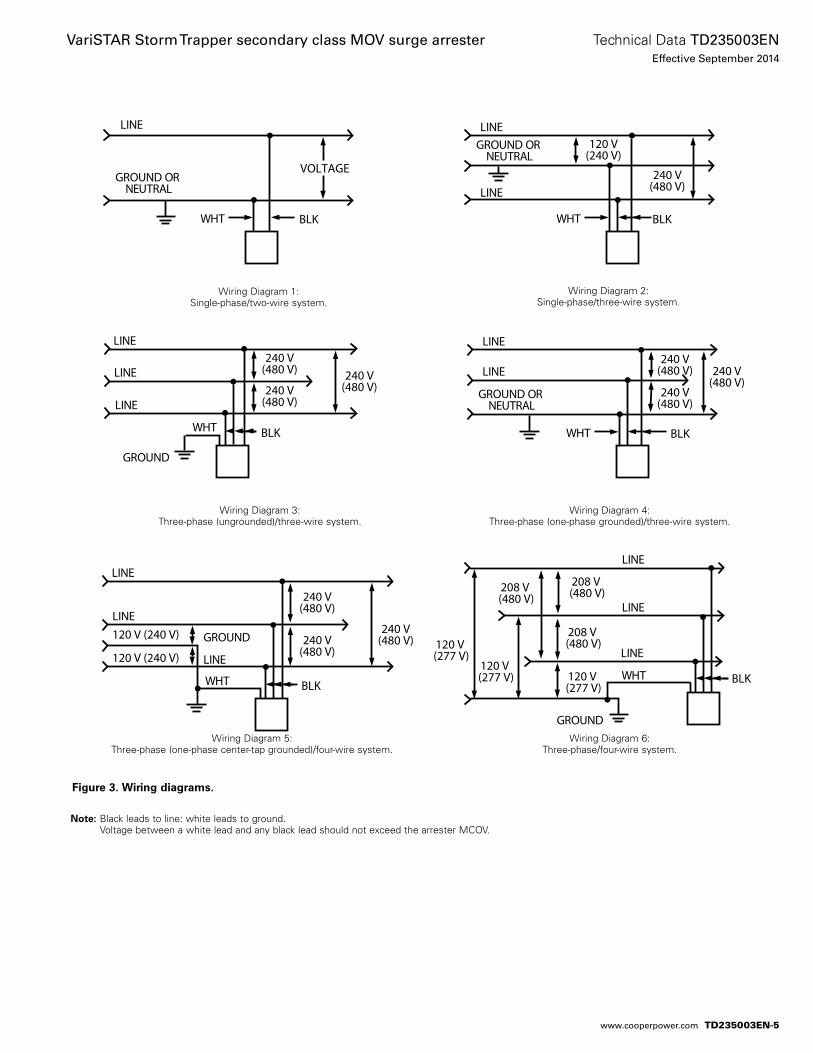
Wiring Diagram 3: Three-phase (ungrounded)/three-wire system.
Wiring Diagram 1: Single-phase/two-wire system.
Wiring Diagram 2: Single-phase/three-wire system.
Wiring Diagram 4: Three-phase (one-phase grounded)/three-wire system.
Wiring Diagram 5: Three-phase (one-phase center-tap grounded)/four-wire system.
Wiring Diagram 6: Three-phase/four-wire system.
Figure 3. Wiring diagrams.
otee:N Black leads to line: white leads to ground. Voltage between a white lead and any black lead should not exceed the arrester MCOV.
LINE
GROUND OR NEUTRAL
WHT BLK
VOLTAGE
LINE
LINE
GROUND OR NEUTRAL
WHT BLK
240 V(480 V)
120 V(240 V)
LINE
LINE
LINE
GROUND
WHT BLK
240 V(480 V)
240 V(480 V)
240 V(480 V)
LINE
LINE
LINE
GROUND
WHT BLK
240 V(480 V)240 V
(480 V)
240 V(480 V)
120 V (240 V)
120 V (240 V)
LINE
LINE
LINE
GROUND
WHT BLK120 V (277 V)
120 V (277 V)
208 V (480 V)
120 V (277 V)
208 V (480 V)
208 V (480 V)
LINE
LINE
GROUND OR NEUTRAL
WHT BLK
240 V(480 V)
240 V(480 V)
240 V(480 V)
TD235003EN-5
Technical Data TD235003ENEffective September 2014
VariSTAR Storm Trapper secondary class MOV surge arrester
www.cooperpower.com
TD235003EN-6
Technical Data TD235003ENEffective September 2014
VariSTAR Storm Trapper secondary class MOV surge arrester
www.cooperpower.com
TD235003EN-7
Technical Data TD235003ENEffective September 2014
VariSTAR Storm Trapper secondary class MOV surge arrester
www.cooperpower.com
Eaton, Cooper Power Systems, VariSTAR, and Storm Trapper are valuable trademarks of Eaton in the U.S. and other countries. You are not permitted to use the these trademarks without the prior written consent of Eaton.IEEE Std C62.11™-1993 standard is a trademark of the Institute of Electrical and Electronics Engineers, Inc., (IEEE). This pub-lication is not endorsed or approved by the IEEE.CSA® is a registered trademark of Canadian Standards Association.
VariSTAR Storm Trapper secondary class MOV surge arrester
Eaton1000 Eaton BoulevardCleveland, OH 44122United StatesEaton.com
Eaton’s Cooper Power Systems Business2300 Badger DriveWaukesha, WI 53188United StatesCooperpower.com
© 2014 EatonAll Rights ReservedPrinted in USAPublication No. TD235003EN
Technical Data TD235003ENEffective September 2014
For Eaton’s Cooper Power Systems VariSTAR Storm Trapper surge arrester product information call 1-877-277-4636 or visit: www.cooperpower.com.
TD235003EN-8
Storm Trapper™ H.E. (high energy) low-voltage distribution-class MOV surge arrester
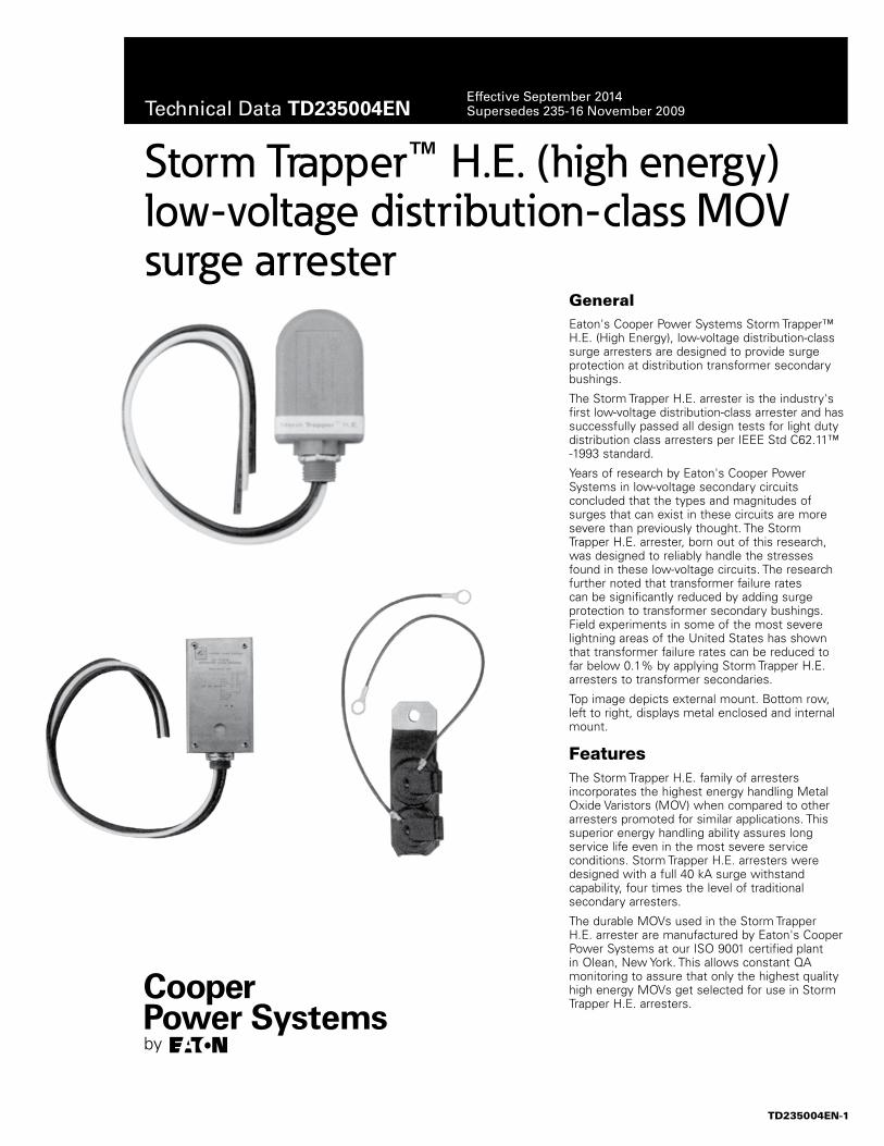
GeneralEaton's Cooper Power Systems Storm Trapper™ H.E. (High Energy), low-voltage distribution-class surge arresters are designed to provide surge protection at distribution transformer secondary bushings.
The Storm Trapper H.E. arrester is the industry's first low-voltage distribution-class arrester and has successfully passed all design tests for light duty distribution class arresters per IEEE Std C62.11™ -1993 standard.
Years of research by Eaton's Cooper Power Systems in low-voltage secondary circuits concluded that the types and magnitudes of surges that can exist in these circuits are more severe than previously thought. The Storm Trapper H.E. arrester, born out of this research, was designed to reliably handle the stresses found in these low-voltage circuits. The research further noted that transformer failure rates can be significantly reduced by adding surge protection to transformer secondary bushings. Field experiments in some of the most severe lightning areas of the United States has shown that transformer failure rates can be reduced to far below 0.1% by applying Storm Trapper H.E. arresters to transformer secondaries.
Top image depicts external mount. Bottom row, left to right, displays metal enclosed and internal mount.
FeaturesThe Storm Trapper H.E. family of arresters incorporates the highest energy handling Metal Oxide Varistors (MOV) when compared to other arresters promoted for similar applications. This superior energy handling ability assures long service life even in the most severe service conditions. Storm Trapper H.E. arresters were designed with a full 40 kA surge withstand capability, four times the level of traditional secondary arresters.
The durable MOVs used in the Storm Trapper H.E. arrester are manufactured by Eaton's Cooper Power Systems at our ISO 9001 certified plant in Olean, New York. This allows constant QA monitoring to assure that only the highest quality high energy MOVs get selected for use in Storm Trapper H.E. arresters.
TD235004EN-1
Technical Data TD235004ENEffective September 2014Supersedes 235-16 November 2009
Features and detailed description
CO
OP
ER
PO
WE
R S
YS
TEM
S
LOW
VO
LTA
GE
DIS
TRIB
UTI
ON
SU
RG
E A
RR
ES
TER
Storm Trapper H.E.R
STO
RM
TR
AP
PE
R H
.E.
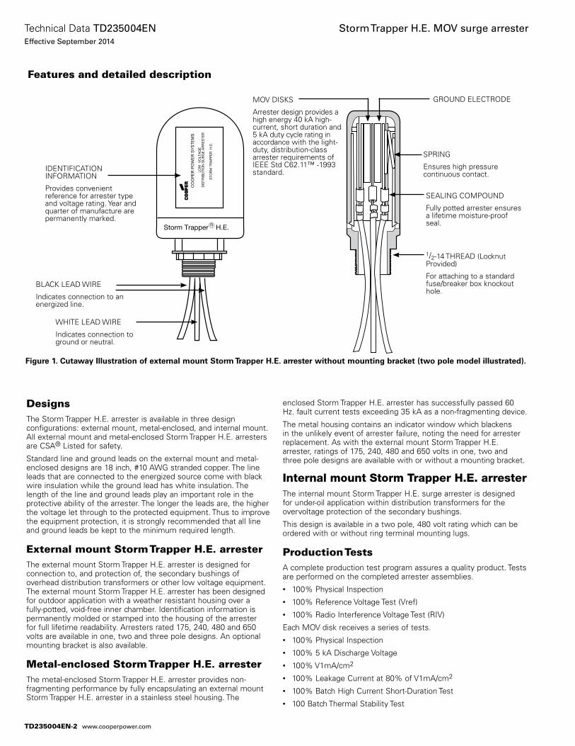
IDENTIFICATION INFORMATION
Provides convenient reference for arrester type and voltage rating. Year and quarter of manufacture are permanently marked.
MOV DISKS
Arrester design provides a high energy 40 kA high-current, short duration and 5 kA duty cycle rating in accordance with the light-duty, distribution-class arrester requirements of IEEE Std C62.11™ -1993 standard.
GROUND ELECTRODE
SPRING
Ensures high pressure continuous contact.
SEALING COMPOUND
Fully potted arrester ensures a lifetime moisture-proof seal.
1/2-14 THREAD (Locknut Provided)
For attaching to a standard fuse/breaker box knockout hole.
BLACK LEAD WIRE
Indicates connection to an energized line.
WHITE LEAD WIRE
Indicates connection to ground or neutral.
Figure 1. Cutaway Illustration of external mount Storm Trapper H.E. arrester without mounting bracket (two pole model illustrated).
DesignsThe Storm Trapper H.E. arrester is available in three design configurations: external mount, metal-enclosed, and internal mount. All external mount and metal-enclosed Storm Trapper H.E. arresters are CSA® Listed for safety.
Standard line and ground leads on the external mount and metal-enclosed designs are 18 inch, #10 AWG stranded copper. The line leads that are connected to the energized source come with black wire insulation while the ground lead has white insulation. The length of the line and ground leads play an important role in the protective ability of the arrester. The longer the leads are, the higher the voltage let through to the protected equipment. Thus to improve the equipment protection, it is strongly recommended that all line and ground leads be kept to the minimum required length.
External mount Storm Trapper H.E. arresterThe external mount Storm Trapper H.E. arrester is designed for connection to, and protection of, the secondary bushings of overhead distribution transformers or other low voltage equipment. The external mount Storm Trapper H.E. arrester has been designed for outdoor application with a weather resistant housing over a fully-potted, void-free inner chamber. Identification information is permanently molded or stamped into the housing of the arrester for full lifetime readability. Arresters rated 175, 240, 480 and 650 volts are available in one, two and three pole designs. An optional mounting bracket is also available.
Metal-enclosed Storm Trapper H.E. arresterThe metal-enclosed Storm Trapper H.E. arrester provides non-fragmenting performance by fully encapsulating an external mount Storm Trapper H.E. arrester in a stainless steel housing. The
enclosed Storm Trapper H.E. arrester has successfully passed 60 Hz. fault current tests exceeding 35 kA as a non-fragmenting device.
The metal housing contains an indicator window which blackens in the unlikely event of arrester failure, noting the need for arrester replacement. As with the external mount Storm Trapper H.E. arrester, ratings of 175, 240, 480 and 650 volts in one, two and three pole designs are available with or without a mounting bracket.
Internal mount Storm Trapper H.E. arresterThe internal mount Storm Trapper H.E. surge arrester is designed for under-oil application within distribution transformers for the overvoltage protection of the secondary bushings.
This design is available in a two pole, 480 volt rating which can be ordered with or without ring terminal mounting lugs.
Production Tests A complete production test program assures a quality product. Tests are performed on the completed arrester assemblies. • 100% Physical Inspection • 100% Reference Voltage Test (Vref)• 100% Radio Interference Voltage Test (RIV)
Each MOV disk receives a series of tests. • 100% Physical Inspection• 100% 5 kA Discharge Voltage • 100% V1mA/cm2
• 100% Leakage Current at 80% of V1mA/cm2
• 100% Batch High Current Short-Duration Test• 100 Batch Thermal Stability Test
TD235004EN-2
Technical Data TD235004ENEffective September 2014
Storm Trapper H.E. MOV surge arrester
www.cooperpower.com
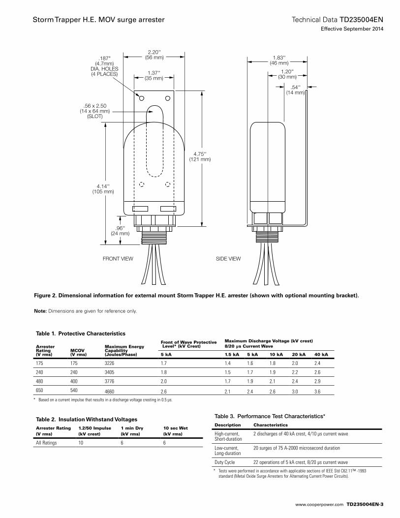
Figure 2. Dimensional information for external mount Storm Trapper H.E. arrester (shown with optional mounting bracket).
otee:N Dimensions are given for reference only.
Table 1. Protective Characteristics
ArresterRating(V rms)
MCOV(V rms)
Maximum EnergyCapability (Joules/Phase)
Front of Wave Protective Level* (kV Crest)
Maximum Discharge Voltage (kV crest)8/20 µs Current Wave
5 kA 1.5 kA 5 kA 10 kA 20 kA 40 kA
175 175 3226 1.7 1.4 1.6 1.8 2.0 2.4
240 240 3405 1.8 1.5 1.7 1.9 2.2 2.6
480 400 3776 2.0 1.7 1.9 2.1 2.4 2.9
650 540 4660 2.6 2.1 2.4 2.6 3.0 3.6
Table 2. Insulation Withstand Voltages
Arrester Rating(V rms)
1.2/50 Impulse(kV crest)
1 min Dry(kV rms)
10 sec Wet(kV rms)
All Ratings 10 6 6
* Based on a current impulse that results in a discharge voltage cresting in 0.5 µs.
* Tests were performed in accordance with applicable sections of IEEE Std C62.11™ -1993 standard (Metal Oxide Surge Arresters for Alternating Current Power Circuits).
1.20''(30 mm)
1.83''(46 mm)
.54''(14 mm)
SIDE VIEWFRONT VIEW
4.14''(105 mm)
2.20''(56 mm)
1.37''(35 mm)
.96''(24 mm)
4.75''(121 mm)
.56 x 2.50(14 x 64 mm)
(SLOT)
.187"(4.7mm)
DIA. HOLES(4 PLACES)
Table 3. Performance Test Characteristics*
Description Characteristics
High-current,Short-duration
2 discharges of 40 kA crest, 4/10 µs current wave
Low-current,Long-duration
20 surges of 75 A-2000 microsecond duration
Duty Cycle 22 operations of 5 kA crest, 8/20 µs current wave
TD235004EN-3
Technical Data TD235004ENEffective September 2014
Storm Trapper H.E. MOV surge arrester
www.cooperpower.com
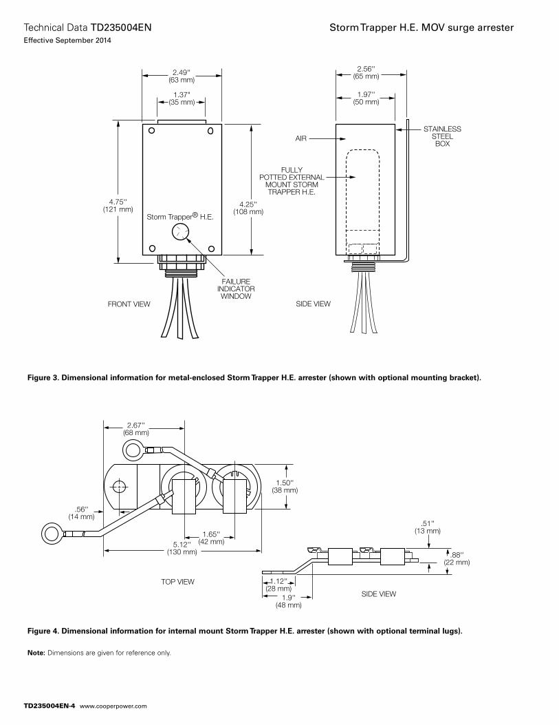
2.49''(63 mm)
4.25''(108 mm)
4.75''(121 mm)
FRONT VIEW SIDE VIEW
FAILUREINDICATORWINDOW
FULLYPOTTED EXTERNAL
MOUNT STORMTRAPPER H.E.
AIR
2.56''(65 mm)
1.97''(50 mm)
STAINLESSSTEELBOX
1.37"(35 mm)
Storm Trapper® H.E.
Figure 4. Dimensional information for internal mount Storm Trapper H.E. arrester (shown with optional terminal lugs).
otee:N Dimensions are given for reference only.
Figure 3. Dimensional information for metal-enclosed Storm Trapper H.E. arrester (shown with optional mounting bracket).
1.50''(38 mm)
5.12''(130 mm)
2.67''(68 mm)
.56''(14 mm)
1.65''(42 mm)
SIDE VIEW
TOP VIEW
.51''(13 mm)
.88''(22 mm)
1.9''(48 mm)
1.12''(28 mm)
TD235004EN-4
Technical Data TD235004ENEffective September 2014
Storm Trapper H.E. MOV surge arrester
www.cooperpower.com
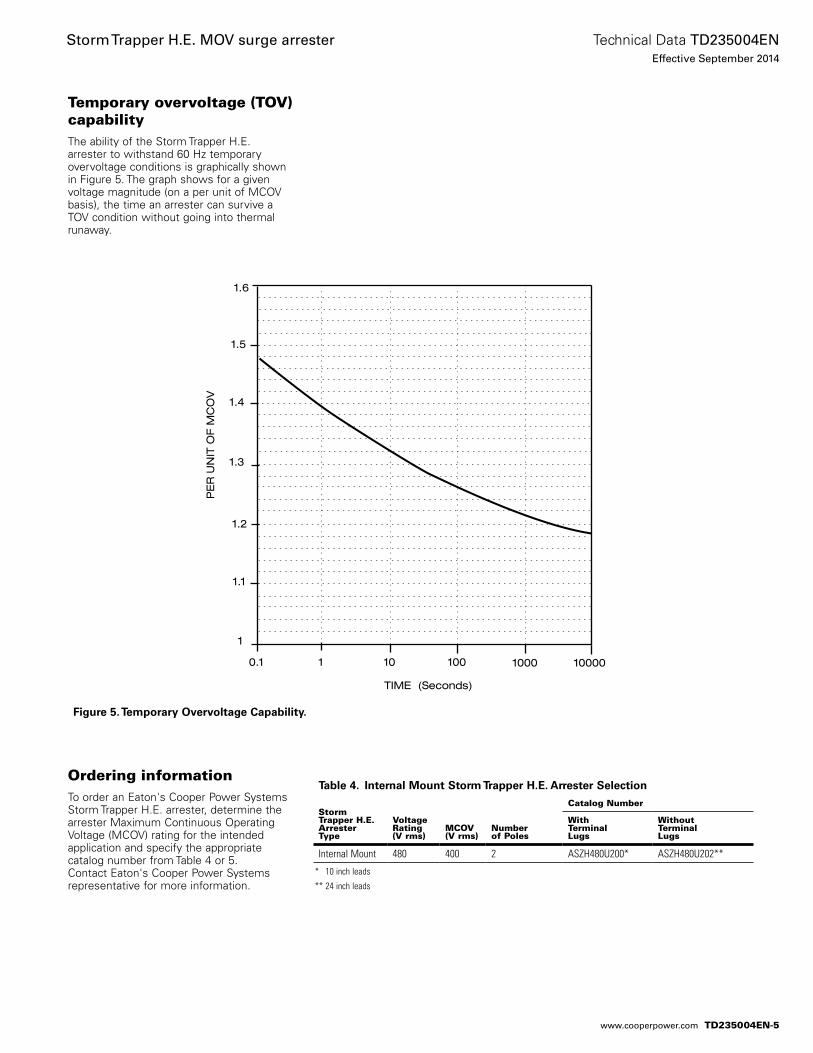
Temporary overvoltage (TOV) capabilityThe ability of the Storm Trapper H.E. arrester to withstand 60 Hz temporary overvoltage conditions is graphically shown in Figure 5. The graph shows for a given voltage magnitude (on a per unit of MCOV basis), the time an arrester can survive a TOV condition without going into thermal runaway.
Ordering informationTo order an Eaton's Cooper Power Systems Storm Trapper H.E. arrester, determine the arrester Maximum Continuous Operating Voltage (MCOV) rating for the intended application and specify the appropriate catalog number from Table 4 or 5. Contact Eaton's Cooper Power Systems representative for more information.
TIME (Seconds)
1 10 100 10000.1
1
1.1
1.3
1.4
1.5
1.6
PE
R U
NIT
OF M
CO
V
10000
1.2
Figure 5. Temporary Overvoltage Capability.
Table 4. Internal Mount Storm Trapper H.E. Arrester Selection
Storm Trapper H.E.ArresterType
VoltageRating(V rms)
MCOV(V rms)
Numberof Poles
Catalog Number
WithTerminal Lugs
WithoutTerminalLugs
Internal Mount 480 400 2 ASZH480U200* ASZH480U202**
* 10 inch leads
** 24 inch leads
TD235004EN-5
Technical Data TD235004ENEffective September 2014
Storm Trapper H.E. MOV surge arrester
www.cooperpower.com
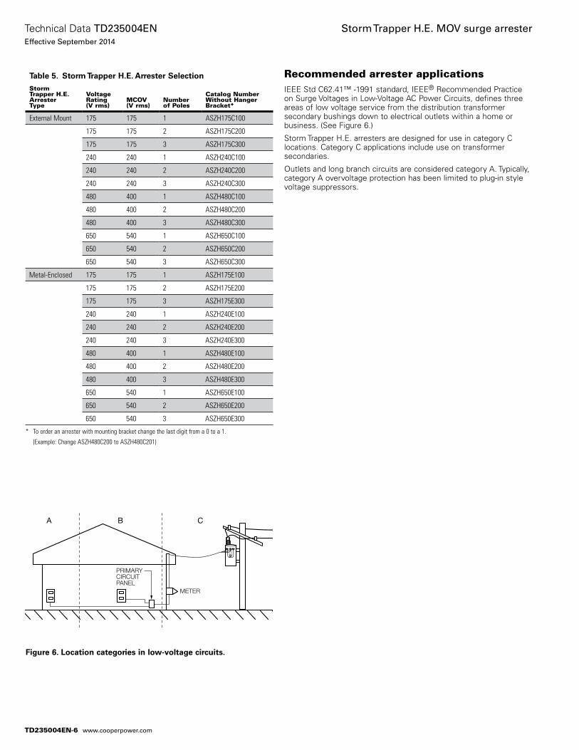
Recommended arrester applicationsIEEE Std C62.41™ -1991 standard, IEEE® Recommended Practice on Surge Voltages in Low-Voltage AC Power Circuits, defines three areas of low voltage service from the distribution transformer secondary bushings down to electrical outlets within a home or business. (See Figure 6.)
Storm Trapper H.E. arresters are designed for use in category C locations. Category C applications include use on transformer secondaries.
Outlets and long branch circuits are considered category A. Typically, category A overvoltage protection has been limited to plug-in style voltage suppressors.
Figure 6. Location categories in low-voltage circuits.
Table 5. Storm Trapper H.E. Arrester Selection
StormTrapper H.E.ArresterType
VoltageRating(V rms)
MCOV(V rms)
Numberof Poles
Catalog NumberWithout HangerBracket*
External Mount 175 175 1 ASZH175C100
175 175 2 ASZH175C200
175 175 3 ASZH175C300
240 240 1 ASZH240C100
240 240 2 ASZH240C200
240 240 3 ASZH240C300
480 400 1 ASZH480C100
480 400 2 ASZH480C200
480 400 3 ASZH480C300
650 540 1 ASZH650C100
650 540 2 ASZH650C200
650 540 3 ASZH650C300
Metal-Enclosed 175 175 1 ASZH175E100
175 175 2 ASZH175E200
175 175 3 ASZH175E300
240 240 1 ASZH240E100
240 240 2 ASZH240E200
240 240 3 ASZH240E300
480 400 1 ASZH480E100
480 400 2 ASZH480E200
480 400 3 ASZH480E300
650 540 1 ASZH650E100
650 540 2 ASZH650E200
650 540 3 ASZH650E300
* To order an arrester with mounting bracket change the last digit from a 0 to a 1.
(Example: Change ASZH480C200 to ASZH480C201)
A B C
PRIMARYCIRCUIT PANEL
METER
COOPERINDUSTRIES C
OO
PER POW
ER SYSTEMS
LOW VOLTAGE
DISTRIBUTION SURGE ARRESTER
ASZ4C1RATEDMCOV
480V400V
2 / POLE
TD235004EN-6
Technical Data TD235004ENEffective September 2014
Storm Trapper H.E. MOV surge arrester
www.cooperpower.com
This page intentionally left blank.
TD235004EN-7
Technical Data TD235004ENEffective September 2014
Storm Trapper H.E. MOV surge arrester
www.cooperpower.com
Eaton, Cooper Power Systems, and Storm Trapper are valuable trademarks of Eaton in the U.S. and other countries. You are not per-mitted to use the these trademarks without the prior written consent of Eaton.CSA® is a registered trademark of Canadian Standards Association.IEEE Std C62.11™ -1993 and IEEE Std C62.41™ -1991 standards are trademarks of the Institute of Electrical and Electronics Engineers, Inc. (IEEE). This publication/product is not endorsed or approved by the IEEE.IEEE® is a registered trademark of the Institute of Electrical and Electronics Engineers, Inc.
Storm Trapper H.E. MOV surge arrester
Eaton1000 Eaton BoulevardCleveland, OH 44122United StatesEaton.com
Eaton’s Cooper Power Systems Business2300 Badger DriveWaukesha, WI 53188United StatesCooperpower.com
© 2014 EatonAll Rights ReservedPrinted in USAPublication No. TD235004EN
Technical Data TD235004ENEffective September 2014
For Eaton's Cooper Power Systems Storm Trapper H.E. MOV surge arrester product information call 1-877-277-4636 or visit: www.cooperpower.com.
TD235004EN-8
Arrester/flipper fuse combinations
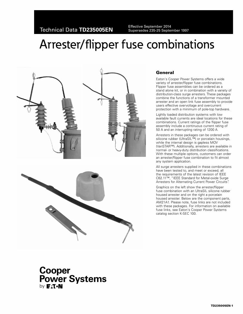
GeneralEaton's Cooper Power Systems offers a wide variety of arrester/flipper fuse combinations. Flipper fuse assemblies can be ordered as a stand alone kit, or in combination with a variety of distribution-class surge arresters. These packages combine the functions of a transformer mounted arrester and an open link fuse assembly to provide users effective overvoltage and overcurrent protection with a minimum of pole -top hardware.
Lightly loaded distribution systems with low available fault currents are ideal locations for these combinations. Current ratings of the flipper fuse assembly include a continuous current rating of 50 A and an interrupting rating of 1200 A.
Arresters in these packages can be ordered with silicone rubber (UltraSIL™) or porcelain housings, while the internal design is gapless MOV (VariSTAR™). Additionally, arresters are available in normal- or heavy-duty distribution classifications. With these multiple options, customers can order an arrester/flipper fuse combination to fit almost any system application.
All surge arresters supplied in these combinations have been tested to, and meet or exceed, all the requirements of the latest revision of IEEE C62.11™, “IEEE Standard for Metal-oxide Surge Arresters for Alternating Current Power Circuits”.
Graphics on the left show the arrester/flipper fuse combination with an UltraSIL silicone rubber housed arrester and on the right a porcelain housed arrester. Below are the component parts, AM21A1. Please note, fuse links are not included with these packages. For information on available fuse links, see Eaton's Cooper Power Systems catalog section K-SEC 100.
TD235005EN-1
Technical Data TD235005ENEffective September 2014Supersedes 235-25 September 1997
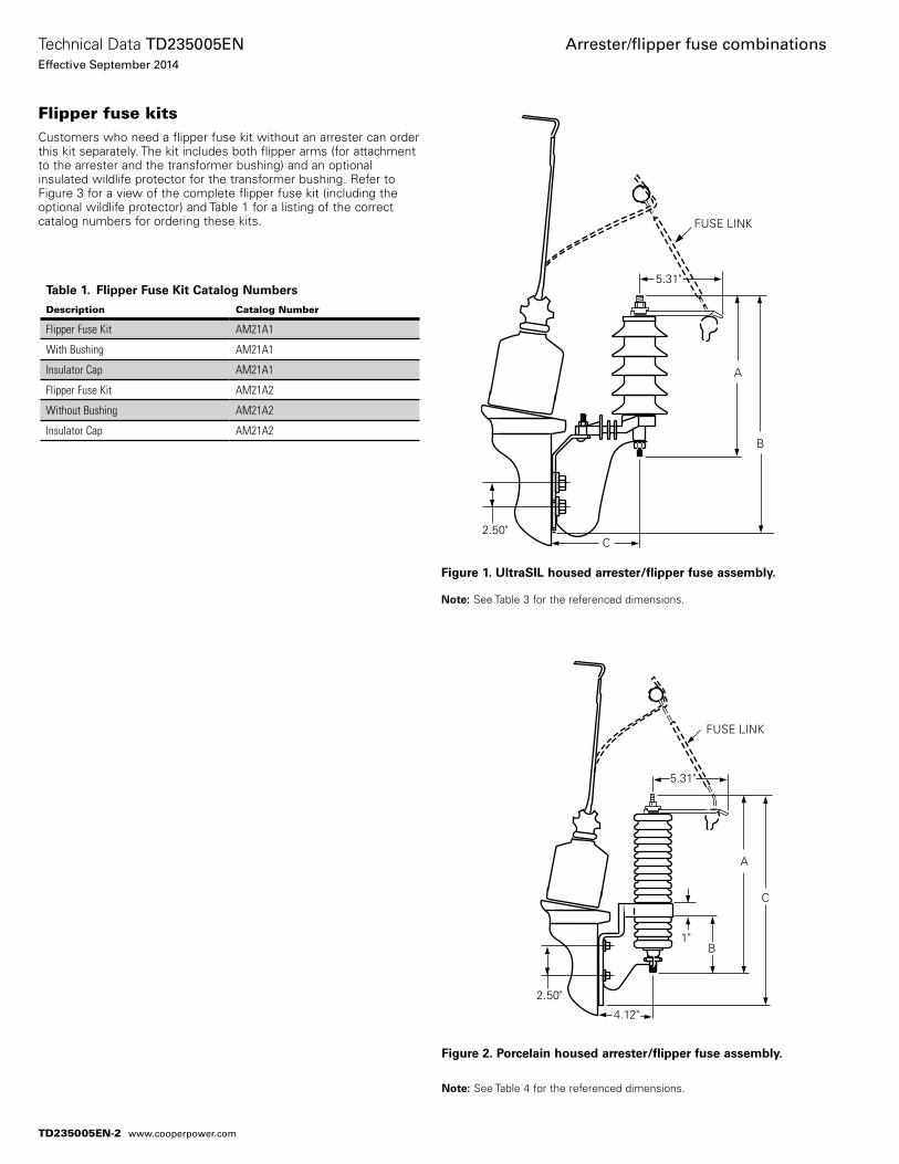
Flipper fuse kitsCustomers who need a flipper fuse kit without an arrester can order this kit separately. The kit includes both flipper arms (for attachment to the arrester and the transformer bushing) and an optional insulated wildlife protector for the transformer bushing. Refer to Figure 3 for a view of the complete flipper fuse kit (including the optional wildlife protector) and Table 1 for a listing of the correct catalog numbers for ordering these kits.
Table 1. Flipper Fuse Kit Catalog Numbers
Description Catalog Number
Flipper Fuse Kit AM21A1
With Bushing AM21A1
Insulator Cap AM21A1
Flipper Fuse Kit AM21A2
Without Bushing AM21A2
Insulator Cap AM21A2
Figure 1. UltraSIL housed arrester/flipper fuse assembly.
otee:N See Table 3 for the referenced dimensions.
FUSE LINK
2.50"C
B
A
5.31"
Figure 2. Porcelain housed arrester/flipper fuse assembly.
otee:N See Table 4 for the referenced dimensions.
180
TOP VIEW
10 1
14 3 5
13
9
FUSE LINK
2.50"
1"B
A
C
5.31"
4.12"
TD235005EN-2
Technical Data TD235005ENEffective September 2014
Arrester/flipper fuse combinations
www.cooperpower.com
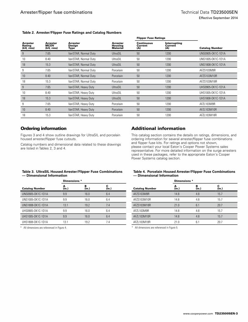
Ordering informationFigures 3 and 4 show outline drawings for UltraSIL and porcelain housed arrester/flipper fuse cutouts.
Catalog numbers and dimensional data related to these drawings are listed in Tables 2, 3 and 4.
Additional information This catalog section contains the details on ratings, dimensions, and ordering information for several arrester/flipper fuse combinations and flipper fuse kits. For ratings and options not shown, please contact your local Eaton's Cooper Power Systems sales representative. For more detailed information on the surge arresters used in these packages, refer to the appropriate Eaton's Cooper Power Systems catalog section.
Table 2. Arrester/Flipper Fuse Ratings and Catalog Numbers
ArresterRating(kV, rms)
ArresterMCOV(kV, rms)
ArresterDesignType
ArresterHousingMaterial
Flipper Fuse Ratings
Catalog Number
ContinuousCurrent(A)
InterruptingCurrent(A)
9 7.65 VariSTAR, Normal Duty UltraSIL 50 1200 UNS0905-OK1C-1D1A
10 8.40 VariSTAR, Normal Duty UltraSIL 50 1200 UNS1005-OK1C-1D1A
18 15.3 VariSTAR, Normal Duty UltraSIL 50 1200 UNS1808-OK1C-1D1A
9 7.65 VariSTAR, Normal Duty Porcelain 50 1200 AFZS103M9R
10 8.40 VariSTAR, Normal Duty Porcelain 50 1200 AFZS103M10R
18 15.3 VariSTAR, Normal Duty Porcelain 50 1200 AFZS103M18R
9 7.65 VariSTAR, Heavy Duty UltraSIL 50 1200 UHS0905-OK1C-1D1A
10 8.40 VariSTAR, Heavy Duty UltraSIL 50 1200 UHS1005-OK1C-1D1A
18 15.3 VariSTAR, Heavy Duty UltraSIL 50 1200 UHS1808-OK1C-1D1A
9 7.65 VariSTAR, Heavy Duty Porcelain 50 1200 AFZL103M9R
10 8.40 VariSTAR, Heavy Duty Porcelain 50 1200 AFZL103M10R
18 15.3 VariSTAR, Heavy Duty Porcelain 50 1200 AFZL103M18R
Table 3. UltraSIL Housed Arrester/Flipper Fuse Combinations –– Dimensional Information
Catalog Number
Dimensions *
A(in.)
B(in.)
C(in.)
UNS0905-OK1C-1D1A 9.9 16.0 6.4
UNS1005-OK1C-1D1A 9.9 16.0 6.4
UNS1808-OK1C-1D1A 13.1 19.2 7.4
UHS0905-OK1C-1D1A 9.9 16.0 6.4
UHS1005-OK1C-1D1A 9.9 16.0 6.4
UHS1808-OK1C-1D1A 13.1 19.2 7.4
* All dimensions are referenced in Figure 4.
Table 4. Porcelain Housed Arrester/Flipper Fuse Combinations –– Dimensional Information
Catalog Number
Dimensions *
A(in.)
B(in.)
C(in.)
AFZS103M9R 14.8 4.8 15.7
AFZS103M10R 14.8 4.8 15.7
AFZS103M18R 21.0 6.1 20.7
AFZL103M9R 14.8 4.8 15.7
AFZL103M10R 14.8 4.8 15.7
AFZL103M18R 21.0 6.1 20.7
* All dimensions are referenced in Figure 5.
TD235005EN-3
Technical Data TD235005ENEffective September 2014
Arrester/flipper fuse combinations
www.cooperpower.com
TD235005EN-4
Eaton, Cooper Power Systems, UltraSIL, and VariSTAR are valuable trademarks of Eaton in the U.S. and other countries. You are not permitted to use the these trademarks without the prior written consent of Eaton.IEEE Std C62.11 standard is a trademark of the Institute of Electrical and Electronics Engineers, Inc., (IEEE). This publication is not endorsed or approved by the IEEE.
Arrester/flipper fuse combinations
Eaton1000 Eaton BoulevardCleveland, OH 44122United StatesEaton.com
Eaton’s Cooper Power Systems Business2300 Badger DriveWaukesha, WI 53188United StatesCooperpower.com
© 2014 EatonAll Rights ReservedPrinted in USAPublication No. TD235005EN
Technical Data TD235005ENEffective September 2014
For Eaton's Cooper Power Systems arrester/flipper fuse combinations product information call 1-877-277-4636 or visit: www.cooperpower.com.
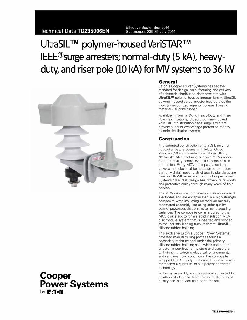
Eaton's Cooper Power Systems has set the standard for design, manufacturing and delivery of polymeric distribution-class arresters with UltraSIL™ polymer-housed arrester family. UltraSIL polymer-housed surge arrester incorporates the industry recognized superior polymer housing material – silicone rubber.
Available in Normal Duty, Heavy-Duty and Riser Pole classifications, UltraSIL polymer-housed VariSTAR™ distribution-class surge arresters provide superior overvoltage protection for any electric distribution system.
ConstructionThe patented construction of UltraSIL polymer-housed arresters begins with Metal Oxide Varistors (MOVs) manufactured at our Olean, NY facility. Manufacturing our own MOVs allows for strict quality control over all aspects of disk production. Every MOV must pass a series of physical and electrical tests designed to ensure that only disks meeting strict quality standards are used in UltraSIL arresters. Eaton's Cooper Power Systems MOV disk design has proven its reliability and protective ability through many years of field service.
The MOV disks are combined with aluminum end electrodes and are encapsulated in a high-strength composite wrap insulating material on our fully automated assembly line using strict quality control processes that eliminate manufacturing variances. The composite collar is cured to the MOV disk stack to form a solid insulation MOV disk module system that is inserted and bonded to the industry leading track resistant UltraSIL silicone rubber housing.
This exclusive Eaton's Cooper Power Systems patented manufacturing process forms a secondary moisture seal under the primary silicone rubber housing seal, which makes the arrester impervious to moisture and capable of withstanding extreme electrical, environmental and cantilever load conditions. The composite wrapped UltraSIL polymer-housed arrester design represents a quantum leap in polymer arrester technology.
Following assembly, each arrester is subjected to a battery of electrical tests to assure the highest quality and in-service field performance.
UltraSIL™ polymer-housed VariSTAR™ IEEE®surge arresters; normal-duty (5 kA), heavy-duty, and riser pole (10 kA) for MV systems to 36 kV
General
TD235006EN-1
Technical Data TD235006ENEffective September 2014Supersedes 235-35 July 2014
FeaturesUltraSIL silicone rubber polymer-housing has undergone a wide range of design tests to determine the optimum shed configuration. In addition, long term environmental testing has verified the lifetime superiority of silicone rubber when compared to other polymeric insulating materials.
Independent laboratory tests have verified the superiority of silicone rubber in terms of non-wetting surfaces, resistance to UV degradation and surface tracking, performance in contaminated environments, chemical inertness, temperature stability and other important insulating properties. UltraSIL silicone rubber polymer-housing will not support biological growth (algae and mildew), is non-flammable and will not support combustion.
An optional insulated mounting base is available to allow connecting to a wide variety of brackets. The insulated base, made of glass filled polyester, has been designed to provide needed mechanical strength for installation and severe loading conditions.
A ground lead isolator is also available. The isolator removes the ground terminal from the arrester in the unlikely event of arrester failure, thus preventing a permanent system fault. An isolator that has operated gives visual indication of internal damage to the arrester and the need for arrester replacement. See Figure 2 for the isolator operating characteristics.
The optional universal wildlife protector has two self-adjusting "valve" style openings which vary from 0 to 0.75" in diameter, thus allowing for a large variety of conductor/insulation sizes while providing optimum wildlife protection. (See page 11, Figure 8 for a dimensional diagram.)
Customers looking to improve system reliability by minimizing wildlife related outages now have multiple options. In addition to the universal wildlife protector featuring two self-adjusting "valve" style openings, Eaton's Cooper Power Systems also offers the more robust line terminal wildlife guard. The line terminal wildlife guard is easily retrofitted to existing arresters installations and provides increased electrical insulation for the high-voltage terminal of the
arrester. The flexible design of the line terminal wildlife guard allows insertion of the lead wire through the bottom of the integral molded flanges. The access holes molded above the flanges will allow conductor sizes ranging from 0 to 0.50” in diameter (OD). The line terminal wildlife guard geometry allows water to shed away from the surface area of the animal guard while minimizing ice build up and maintaining flexibility through extreme operating temperatures. (Refer to page 11, Figure 9 for a dimensional diagram.)
For complete wildlife resistance, the ground terminal wildlife guard can easily be installed alongside the line terminal wildlife guard or universal wildlife protector. The ground terminal wildlife guard is a compact and economical guard that ensures wildlife is unable to come in contact with energized objects while on a grounded surface.(Refer to page 11, Figure 10 for a dimensional diagram.)
OperationThe operation of VariSTAR arresters is typical of gapless metal oxide arresters. During steady state conditions, line-to-ground voltage is applied continuously across the arrester terminals. When surges occur, VariSTAR arresters immediately limits the overvoltage to the required protective level by conducting the surge current to ground. Upon passage of the surge, the arrester returns to its initial state, conducting minimal leakage current.
The protective characteristics of VariSTAR arresters provide excellent overvoltage protection for distribution system equipment. (See page 6 for protective characteristics.)
Design testingThe housing material, internals and hardware work together as a system and must stand up to years of exposure to environmental extremes.
To assure a superior level of performance, both the components and the assembled arrester units have been subjected to a program of testing that accurately simulates years of exposure to actual field conditions. Testing includes:• IEEE Std C62.11-2005™ standard Testing – Full certification to
the performance requirements by an independent laboratory. A certified test report is available under Bulletin Number 95062. Additional reference documents are listed on page 14.
Production testsA complete production test program ensures a quality product. Each metal oxide varistor receives a series of electrical tests. Quality is demonstrated by a series of destructive tests performed on every batch of varistors. Listed are the tests performed on the varistors:• 100% Physical Inspection• 100% Discharge Voltage test• 100% V1mA/cm2
• 100% Leakage Current at 80% of V1mA/cm2 Voltage (Watts Loss)• Batch High-current, Short-duration test• Batch Thermal Stability test• Batch Aging test
Each fully assembled VariSTAR arrester must pass the following production tests:• 100% Physical Inspection• 100% Leakage Current test • 100% Partial Discharge Inception Voltage test
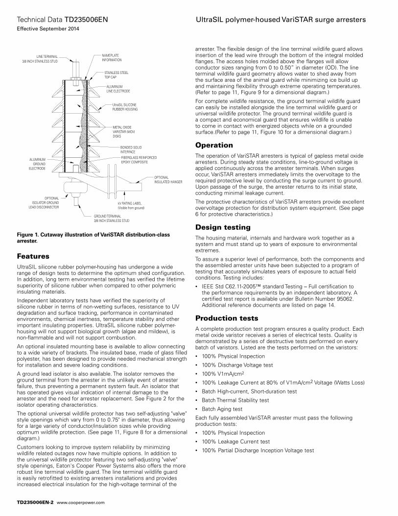
Figure 1. Cutaway illustration of VariSTAR distribution-class arrester.
ALUMINUMLINE ELECTRODE
METAL OXIDEVARISTAR (MOV)DISKS
ALUMINUMGROUND
ELECTRODE
NAMEPLATEINFORMATION
STAINLESS STEELTOP CAP
LINE TERMINAL3/8 INCH STAINLESS STUD
UltraSIL SILICONERUBBER HOUSING
BONDED SOLIDINTERFACE
FIBERGLASS REINFORCEDEPOXY COMPOSITE
OPTIONALINSULATED HANGER
OPTIONALISOLATOR GROUND
LEAD DISCONNECTORkV RATING LABEL(Visible from ground)
GROUND TERMINAL3/8 INCH STAINLESS STUD
TD235006EN-2
Technical Data TD235006ENEffective September 2014
UltraSIL polymer-housed VariSTAR surge arresters
www.cooperpower.com
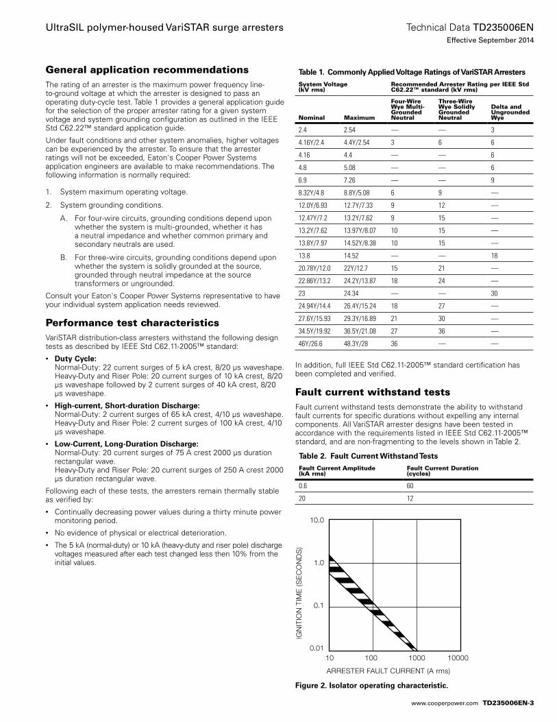
General application recommendationsThe rating of an arrester is the maximum power frequency line-to-ground voltage at which the arrester is designed to pass an operating duty-cycle test. Table 1 provides a general application guide for the selection of the proper arrester rating for a given system voltage and system grounding configuration as outlined in the IEEE Std C62.22™ standard application guide.
Under fault conditions and other system anomalies, higher voltages can be experienced by the arrester. To ensure that the arrester ratings will not be exceeded, Eaton's Cooper Power Systems application engineers are available to make recommendations. The following information is normally required:
1. System maximum operating voltage.
2. System grounding conditions.
A. For four-wire circuits, grounding conditions depend upon whether the system is multi-grounded, whether it has a neutral impedance and whether common primary and secondary neutrals are used.
B. For three-wire circuits, grounding conditions depend upon whether the system is solidly grounded at the source, grounded through neutral impedance at the source transformers or ungrounded.
Consult your Eaton's Cooper Power Systems representative to have your individual system application needs reviewed.
Performance test characteristicsVariSTAR distribution-class arresters withstand the following design tests as described by IEEE Std C62.11-2005™ standard:• Duty Cycle:
Normal-Duty: 22 current surges of 5 kA crest, 8/20 µs waveshape.Heavy-Duty and Riser Pole: 20 current surges of 10 kA crest, 8/20 µs waveshape followed by 2 current surges of 40 kA crest, 8/20 µs waveshape.
• High-current, Short-duration Discharge: Normal-Duty: 2 current surges of 65 kA crest, 4/10 µs waveshape.Heavy-Duty and Riser Pole: 2 current surges of 100 kA crest, 4/10 µs waveshape.
• Low-Current, Long-Duration Discharge: Normal-Duty: 20 current surges of 75 A crest 2000 µs duration rectangular wave. Heavy-Duty and Riser Pole: 20 current surges of 250 A crest 2000 µs duration rectangular wave.
Following each of these tests, the arresters remain thermally stable as verified by:• Continually decreasing power values during a thirty minute power
monitoring period.• No evidence of physical or electrical deterioration.• The 5 kA (normal-duty) or 10 kA (heavy-duty and riser pole) discharge
voltages measured after each test changed less then 10% from the initial values.
In addition, full IEEE Std C62.11-2005™ standard certification has been completed and verified.
Fault current withstand testsFault current withstand tests demonstrate the ability to withstand fault currents for specific durations without expelling any internal components. All VariSTAR arrester designs have been tested in accordance with the requirements listed in IEEE Std C62.11-2005™ standard, and are non-fragmenting to the levels shown in Table 2.
Table 1. Commonly Applied Voltage Ratings of VariSTAR Arresters
System Voltage (kV rms)
Recommended Arrester Rating per IEEE Std C62.22™ standard (kV rms)
Nominal Maximum
Four-Wire Wye Multi-Grounded Neutral
Three-Wire Wye Solidly Grounded Neutral
Delta and Ungrounded Wye
2.4 2.54 — — 3
4.16Y/2.4 4.4Y/2.54 3 6 6
4.16 4.4 — — 6
4.8 5.08 — — 6
6.9 7.26 — — 9
8.32Y/4.8 8.8Y/5.08 6 9 —
12.0Y/6.93 12.7Y/7.33 9 12 —
12.47Y/7.2 13.2Y/7.62 9 15 —
13.2Y/7.62 13.97Y/8.07 10 15 —
13.8Y/7.97 14.52Y/8.38 10 15 ––
13.8 14.52 — — 18
20.78Y/12.0 22Y/12.7 15 21 —
22.86Y/13.2 24.2Y/13.87 18 24 —
23 24.34 — — 30
24.94Y/14.4 26.4Y/15.24 18 27 —
27.6Y/15.93 29.3Y/16.89 21 30 —
34.5Y/19.92 36.5Y/21.08 27 36 —
46Y/26.6 48.3Y/28 36 — —
Table 2. Fault Current Withstand Tests
Fault Current Amplitude (kA rms)
Fault Current Duration (cycles)
0.6 60
20 12
10.0
1.0
0.1
0.0110 100 1000 10000
ARRESTER FAULT CURRENT (A rms)
IGN
ITIO
N T
IME
(SE
CO
ND
S)
Figure 2. Isolator operating characteristic.
TD235006EN-3
Technical Data TD235006ENEffective September 2014
UltraSIL polymer-housed VariSTAR surge arresters
www.cooperpower.com
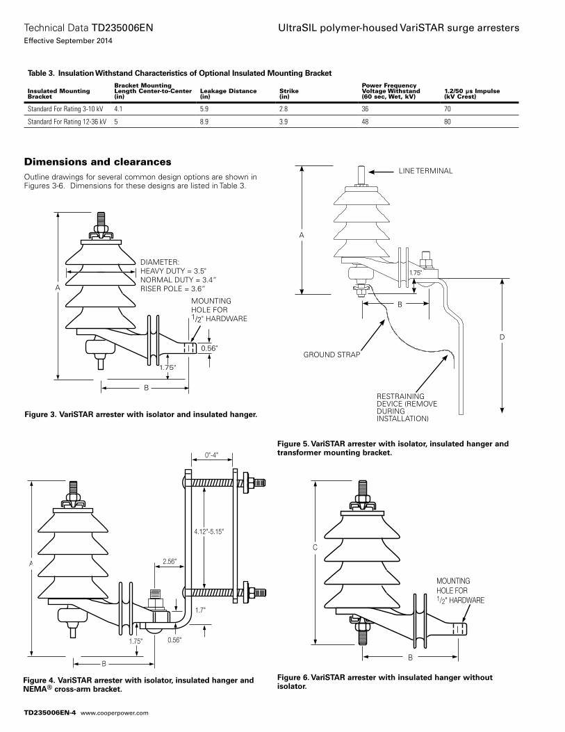
Figure 3. VariSTAR arrester with isolator and insulated hanger.
A
B
DIAMETER:HEAVY DUTY = 3.5"NORMAL DUTY = 3.4”RISER POLE = 3.6”
MOUNTING HOLE FOR 1/2" HARDWARE
0.56"
1.75"
Figure 6. VariSTAR arrester with insulated hanger without isolator.
C
B
MOUNTING HOLE FOR 1/2" HARDWARE
Figure 4. VariSTAR arrester with isolator, insulated hanger and NEMA® cross-arm bracket.
A
0.56"
2.56"
1.7"
4.12"-5.15"
B
0"-4"
1.75"
Dimensions and clearancesOutline drawings for several common design options are shown in Figures 3-6. Dimensions for these designs are listed in Table 3.
Figure 5. VariSTAR arrester with isolator, insulated hanger and transformer mounting bracket.
GROUND STRAP
LINE TERMINAL
RESTRAINING DEVICE (REMOVE DURING INSTALLATION)
D
A
B
1.75"
Table 3. Insulation Withstand Characteristics of Optional Insulated Mounting Bracket
Insulated Mounting Bracket
Bracket Mounting Length Center-to-Center (in)
Leakage Distance(in)
Strike (in)
Power Frequency Voltage Withstand (60 sec, Wet, kV)
1.2/50 μs Impulse (kV Crest)
Standard For Rating 3-10 kV 4.1 5.9 2.8 36 70
Standard For Rating 12-36 kV 5 8.9 3.9 48 80
TD235006EN-4
Technical Data TD235006ENEffective September 2014
UltraSIL polymer-housed VariSTAR surge arresters
www.cooperpower.com
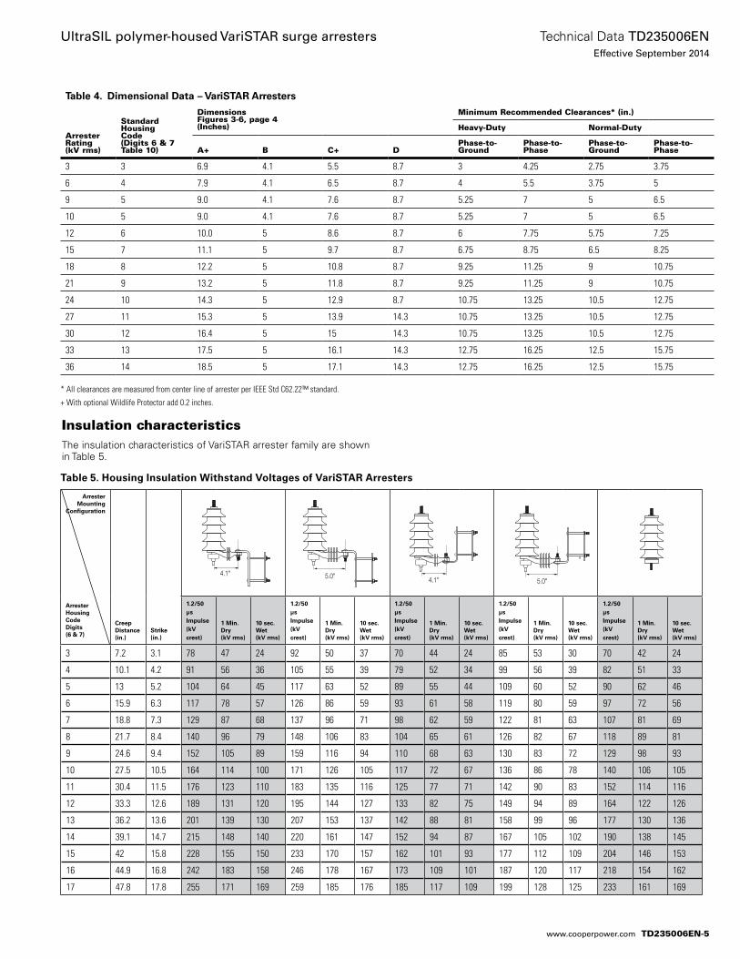
Table 5. Housing Insulation Withstand Voltages of VariSTAR Arresters
Insulation characteristicsThe insulation characteristics of VariSTAR arrester family are shown in Table 5.
Table 4. Dimensional Data – VariSTAR Arresters
Arrester Rating (kV rms)
Standard HousingCode (Digits 6 & 7Table 10)
DimensionsFigures 3-6, page 4 (Inches)
Minimum Recommended Clearances* (in.)
Heavy-Duty Normal-Duty
A+ B C+ DPhase-to-Ground
Phase-to-Phase
Phase-to-Ground
Phase-to-Phase
3 3 6.9 4.1 5.5 8.7 3 4.25 2.75 3.75
6 4 7.9 4.1 6.5 8.7 4 5.5 3.75 5
9 5 9.0 4.1 7.6 8.7 5.25 7 5 6.5
10 5 9.0 4.1 7.6 8.7 5.25 7 5 6.5
12 6 10.0 5 8.6 8.7 6 7.75 5.75 7.25
15 7 11.1 5 9.7 8.7 6.75 8.75 6.5 8.25
18 8 12.2 5 10.8 8.7 9.25 11.25 9 10.75
21 9 13.2 5 11.8 8.7 9.25 11.25 9 10.75
24 10 14.3 5 12.9 8.7 10.75 13.25 10.5 12.75
27 11 15.3 5 13.9 14.3 10.75 13.25 10.5 12.75
30 12 16.4 5 15 14.3 10.75 13.25 10.5 12.75
33 13 17.5 5 16.1 14.3 12.75 16.25 12.5 15.75
36 14 18.5 5 17.1 14.3 12.75 16.25 12.5 15.75
ArresterMounting
Configuration
ArresterHousingCodeDigits (6 & 7)
Creep Distance (in.)
Strike(in.)
4.1" 5.0" 4.1" 5.0"
1.2/50 µs Impulse(kV crest)
1 Min. Dry(kV rms)
10 sec.Wet(kV rms)
1.2/50 µs Impulse(kV crest)
1 Min. Dry(kV rms)
10 sec.Wet(kV rms)
1.2/50 µs Impulse(kV crest)
1 Min. Dry(kV rms)
10 sec.Wet(kV rms)
1.2/50 µs Impulse(kV crest)
1 Min. Dry(kV rms)
10 sec.Wet(kV rms)
1.2/50 µs Impulse(kV crest)
1 Min. Dry(kV rms)
10 sec.Wet(kV rms)
3 7.2 3.1 78 47 24 92 50 37 70 44 24 85 53 30 70 42 24
4 10.1 4.2 91 56 36 105 55 39 79 52 34 99 56 39 82 51 33
5 13 5.2 104 64 45 117 63 52 89 55 44 109 60 52 90 62 46
6 15.9 6.3 117 78 57 126 86 59 93 61 58 119 80 59 97 72 56
7 18.8 7.3 129 87 68 137 96 71 98 62 59 122 81 63 107 81 69
8 21.7 8.4 140 96 79 148 106 83 104 65 61 126 82 67 118 89 81
9 24.6 9.4 152 105 89 159 116 94 110 68 63 130 83 72 129 98 93
10 27.5 10.5 164 114 100 171 126 105 117 72 67 136 86 78 140 106 105
11 30.4 11.5 176 123 110 183 135 116 125 77 71 142 90 83 152 114 116
12 33.3 12.6 189 131 120 195 144 127 133 82 75 149 94 89 164 122 126
13 36.2 13.6 201 139 130 207 153 137 142 88 81 158 99 96 177 130 136
14 39.1 14.7 215 148 140 220 161 147 152 94 87 167 105 102 190 138 145
15 42 15.8 228 155 150 233 170 157 162 101 93 177 112 109 204 146 153
16 44.9 16.8 242 183 158 246 178 167 173 109 101 187 120 117 218 154 162
17 47.8 17.8 255 171 169 259 185 176 185 117 109 199 128 125 233 161 169
* All clearances are measured from center line of arrester per IEEE Std C62.22™ standard.
+ With optional Wildlife Protector add 0.2 inches.
TD235006EN-5
Technical Data TD235006ENEffective September 2014
UltraSIL polymer-housed VariSTAR surge arresters
www.cooperpower.com
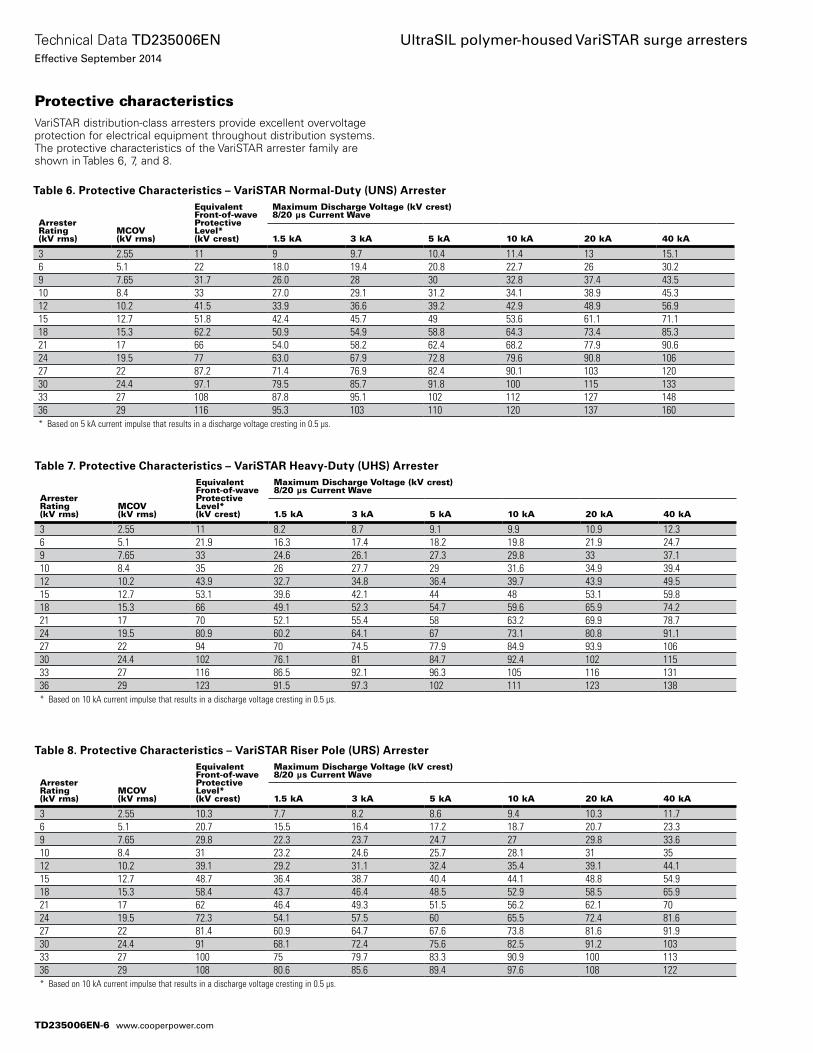
Protective characteristicsVariSTAR distribution-class arresters provide excellent overvoltage protection for electrical equipment throughout distribution systems. The protective characteristics of the VariSTAR arrester family are shown in Tables 6, 7, and 8.
Table 6. Protective Characteristics – VariSTAR Normal-Duty (UNS) Arrester
Arrester Rating (kV rms)
MCOV (kV rms)
Equivalent Front-of-wave Protective Level* (kV crest)
Maximum Discharge Voltage (kV crest) 8/20 µs Current Wave
1.5 kA 3 kA 5 kA 10 kA 20 kA 40 kA
3 2.55 11 9 9.7 10.4 11.4 13 15.16 5.1 22 18.0 19.4 20.8 22.7 26 30.29 7.65 31.7 26.0 28 30 32.8 37.4 43.510 8.4 33 27.0 29.1 31.2 34.1 38.9 45.312 10.2 41.5 33.9 36.6 39.2 42.9 48.9 56.915 12.7 51.8 42.4 45.7 49 53.6 61.1 71.118 15.3 62.2 50.9 54.9 58.8 64.3 73.4 85.321 17 66 54.0 58.2 62.4 68.2 77.9 90.624 19.5 77 63.0 67.9 72.8 79.6 90.8 10627 22 87.2 71.4 76.9 82.4 90.1 103 12030 24.4 97.1 79.5 85.7 91.8 100 115 13333 27 108 87.8 95.1 102 112 127 14836 29 116 95.3 103 110 120 137 160* Based on 5 kA current impulse that results in a discharge voltage cresting in 0.5 µs.
Table 7. Protective Characteristics – VariSTAR Heavy-Duty (UHS) Arrester
Arrester Rating (kV rms)
MCOV (kV rms)
Equivalent Front-of-wave Protective Level* (kV crest)
Maximum Discharge Voltage (kV crest) 8/20 µs Current Wave
1.5 kA 3 kA 5 kA 10 kA 20 kA 40 kA
3 2.55 11 8.2 8.7 9.1 9.9 10.9 12.36 5.1 21.9 16.3 17.4 18.2 19.8 21.9 24.79 7.65 33 24.6 26.1 27.3 29.8 33 37.110 8.4 35 26 27.7 29 31.6 34.9 39.412 10.2 43.9 32.7 34.8 36.4 39.7 43.9 49.515 12.7 53.1 39.6 42.1 44 48 53.1 59.818 15.3 66 49.1 52.3 54.7 59.6 65.9 74.221 17 70 52.1 55.4 58 63.2 69.9 78.724 19.5 80.9 60.2 64.1 67 73.1 80.8 91.127 22 94 70 74.5 77.9 84.9 93.9 10630 24.4 102 76.1 81 84.7 92.4 102 11533 27 116 86.5 92.1 96.3 105 116 13136 29 123 91.5 97.3 102 111 123 138* Based on 10 kA current impulse that results in a discharge voltage cresting in 0.5 µs.
Table 8. Protective Characteristics – VariSTAR Riser Pole (URS) Arrester
Arrester Rating (kV rms)
MCOV (kV rms)
Equivalent Front-of-wave Protective Level* (kV crest)
Maximum Discharge Voltage (kV crest) 8/20 µs Current Wave
1.5 kA 3 kA 5 kA 10 kA 20 kA 40 kA
3 2.55 10.3 7.7 8.2 8.6 9.4 10.3 11.76 5.1 20.7 15.5 16.4 17.2 18.7 20.7 23.39 7.65 29.8 22.3 23.7 24.7 27 29.8 33.610 8.4 31 23.2 24.6 25.7 28.1 31 3512 10.2 39.1 29.2 31.1 32.4 35.4 39.1 44.115 12.7 48.7 36.4 38.7 40.4 44.1 48.8 54.918 15.3 58.4 43.7 46.4 48.5 52.9 58.5 65.921 17 62 46.4 49.3 51.5 56.2 62.1 7024 19.5 72.3 54.1 57.5 60 65.5 72.4 81.627 22 81.4 60.9 64.7 67.6 73.8 81.6 91.930 24.4 91 68.1 72.4 75.6 82.5 91.2 10333 27 100 75 79.7 83.3 90.9 100 11336 29 108 80.6 85.6 89.4 97.6 108 122* Based on 10 kA current impulse that results in a discharge voltage cresting in 0.5 µs.
TD235006EN-6
Technical Data TD235006ENEffective September 2014
UltraSIL polymer-housed VariSTAR surge arresters
www.cooperpower.com
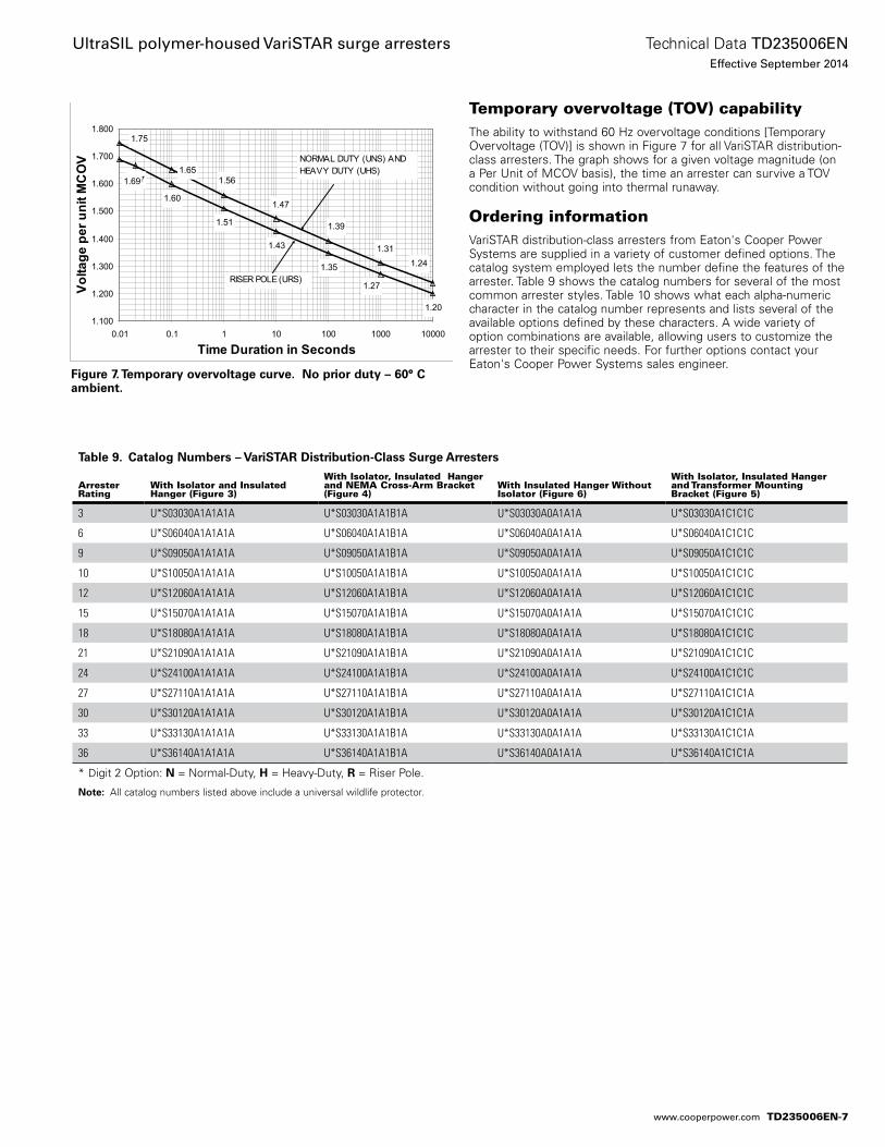
Figure 7. Temporary overvoltage curve. No prior duty – 60° C ambient.
1.67
1.60
1.51
1.43
1.35
1.20
1.241.31
1.39
1.47
1.561.65
1.75
1.69
1.27
1.100
1.200
1.300
1.400
1.500
1.600
1.700
1.800
0.01 0.1 1 10 100 1000 10000
Time Duration in Seconds
Volta
ge p
er u
nit M
CO
V
RISER POLE (URS)
NORMAL DUTY (UNS) AND HEAVY DUTY (UHS)
Temporary overvoltage (TOV) capabilityThe ability to withstand 60 Hz overvoltage conditions [Temporary Overvoltage (TOV)] is shown in Figure 7 for all VariSTAR distribution-class arresters. The graph shows for a given voltage magnitude (on a Per Unit of MCOV basis), the time an arrester can survive a TOV condition without going into thermal runaway.
Ordering informationVariSTAR distribution-class arresters from Eaton's Cooper Power Systems are supplied in a variety of customer defined options. The catalog system employed lets the number define the features of the arrester. Table 9 shows the catalog numbers for several of the most common arrester styles. Table 10 shows what each alpha-numeric character in the catalog number represents and lists several of the available options defined by these characters. A wide variety of option combinations are available, allowing users to customize the arrester to their specific needs. For further options contact your Eaton's Cooper Power Systems sales engineer.
Table 9. Catalog Numbers – VariSTAR Distribution-Class Surge Arresters
Arrester Rating
With Isolator and Insulated Hanger (Figure 3)
With Isolator, Insulated Hanger and NEMA Cross-Arm Bracket (Figure 4)
With Insulated Hanger Without Isolator (Figure 6)
With Isolator, Insulated Hanger and Transformer Mounting Bracket (Figure 5)
3 U*S03030A1A1A1A U*S03030A1A1B1A U*S03030A0A1A1A U*S03030A1C1C1C
6 U*S06040A1A1A1A U*S06040A1A1B1A U*S06040A0A1A1A U*S06040A1C1C1C
9 U*S09050A1A1A1A U*S09050A1A1B1A U*S09050A0A1A1A U*S09050A1C1C1C
10 U*S10050A1A1A1A U*S10050A1A1B1A U*S10050A0A1A1A U*S10050A1C1C1C
12 U*S12060A1A1A1A U*S12060A1A1B1A U*S12060A0A1A1A U*S12060A1C1C1C
15 U*S15070A1A1A1A U*S15070A1A1B1A U*S15070A0A1A1A U*S15070A1C1C1C
18 U*S18080A1A1A1A U*S18080A1A1B1A U*S18080A0A1A1A U*S18080A1C1C1C
21 U*S21090A1A1A1A U*S21090A1A1B1A U*S21090A0A1A1A U*S21090A1C1C1C
24 U*S24100A1A1A1A U*S24100A1A1B1A U*S24100A0A1A1A U*S24100A1C1C1C
27 U*S27110A1A1A1A U*S27110A1A1B1A U*S27110A0A1A1A U*S27110A1C1C1A
30 U*S30120A1A1A1A U*S30120A1A1B1A U*S30120A0A1A1A U*S30120A1C1C1A
33 U*S33130A1A1A1A U*S33130A1A1B1A U*S33130A0A1A1A U*S33130A1C1C1A
36 U*S36140A1A1A1A U*S36140A1A1B1A U*S36140A0A1A1A U*S36140A1C1C1A
* Digit 2 Option: N = Normal-Duty, H = Heavy-Duty, R = Riser Pole.
ote:N All catalog numbers listed above include a universal wildlife protector.
TD235006EN-7
Technical Data TD235006ENEffective September 2014
UltraSIL polymer-housed VariSTAR surge arresters
www.cooperpower.com
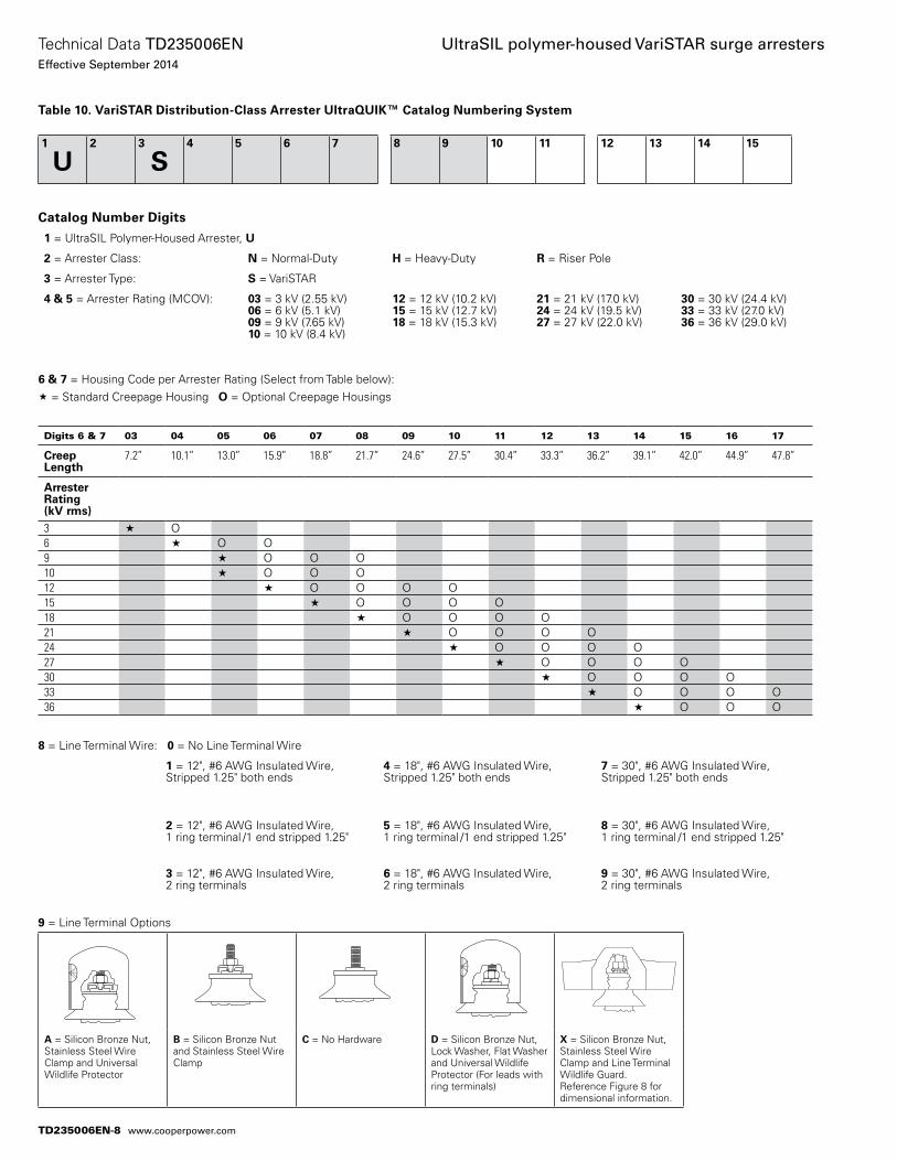
8 = Line Terminal Wire: 0 = No Line Terminal Wire
1 = 12", #6 AWG Insulated Wire, Stripped 1.25" both ends
4 = 18", #6 AWG Insulated Wire, Stripped 1.25" both ends
7 = 30", #6 AWG Insulated Wire,Stripped 1.25" both ends
2 = 12", #6 AWG Insulated Wire, 1 ring terminal /1 end stripped 1.25"
5 = 18", #6 AWG Insulated Wire, 1 ring terminal /1 end stripped 1.25"
8 = 30", #6 AWG Insulated Wire, 1 ring terminal /1 end stripped 1.25"
3 = 12", #6 AWG Insulated Wire, 2 ring terminals
6 = 18", #6 AWG Insulated Wire,2 ring terminals
9 = 30", #6 AWG Insulated Wire, 2 ring terminals
Table 10. VariSTAR Distribution-Class Arrester UltraQUIK™ Catalog Numbering System
Catalog Number Digits
1 = UltraSIL Polymer-Housed Arrester, U
2 = Arrester Class: N = Normal-Duty H = Heavy-Duty R = Riser Pole
3 = Arrester Type: S = VariSTAR
4 & 5 = Arrester Rating (MCOV): 03 = 3 kV (2.55 kV) 06 = 6 kV (5.1 kV)09 = 9 kV (7.65 kV) 10 = 10 kV (8.4 kV)
12 = 12 kV (10.2 kV) 15 = 15 kV (12.7 kV)18 = 18 kV (15.3 kV)
21 = 21 kV (17.0 kV)24 = 24 kV (19.5 kV)27 = 27 kV (22.0 kV)
30 = 30 kV (24.4 kV)33 = 33 kV (27.0 kV)36 = 36 kV (29.0 kV)
9 = Line Terminal Options
A = Silicon Bronze Nut, Stainless Steel Wire Clamp and Universal Wildlife Protector
B = Silicon Bronze Nut and Stainless Steel Wire Clamp
C = No Hardware D = Silicon Bronze Nut, Lock Washer, Flat Washer and Universal Wildlife Protector (For leads with ring terminals)
X = Silicon Bronze Nut, Stainless Steel Wire Clamp and Line Terminal Wildlife Guard. Reference Figure 8 for dimensional information.
Digits 6 & 7 03 04 05 06 07 08 09 10 11 12 13 14 15 16 17
Creep Length
7.2” 10.1” 13.0” 15.9” 18.8” 21.7” 24.6” 27.5” 30.4” 33.3” 36.2” 39.1” 42.0” 44.9” 47.8”
Arrester Rating (kV rms)3 « O6 « O O9 « O O O10 « O O O12 « O O O O15 « O O O O18 « O O O O21 « O O O O24 « O O O O27 « O O O O30 « O O O O33 « O O O O36 « O O O
6 & 7 = Housing Code per Arrester Rating (Select from Table below):« = Standard Creepage Housing O = Optional Creepage Housings
1
U2 3
S4 5 6 7 8 9 10 11 12 13 14 15
TD235006EN-8
Technical Data TD235006ENEffective September 2014
UltraSIL polymer-housed VariSTAR surge arresters
www.cooperpower.com
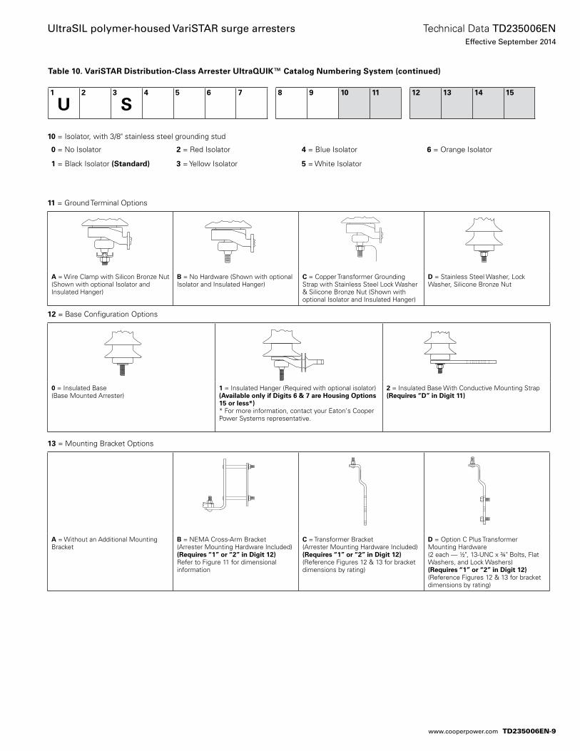
10 = Isolator, with 3/8" stainless steel grounding stud
0 = No Isolator 2 = Red Isolator 4 = Blue Isolator 6 = Orange Isolator
1 = Black Isolator (Standard) 3 = Yellow Isolator 5 = White Isolator
11 = Ground Terminal Options
A = Wire Clamp with Silicon Bronze Nut (Shown with optional Isolator and Insulated Hanger)
B = No Hardware (Shown with optional Isolator and Insulated Hanger)
C = Copper Transformer Grounding Strap with Stainless Steel Lock Washer & Silicone Bronze Nut (Shown with optional Isolator and Insulated Hanger)
D = Stainless Steel Washer, Lock Washer, Silicone Bronze Nut
13 = Mounting Bracket Options
A = Without an Additional Mounting Bracket
B = NEMA Cross-Arm Bracket (Arrester Mounting Hardware Included) (Requires “1” or “2” in Digit 12) Refer to Figure 11 for dimensional information
C = Transformer Bracket(Arrester Mounting Hardware Included)(Requires “1” or “2” in Digit 12)(Reference Figures 12 & 13 for bracket dimensions by rating)
D = Option C Plus Transformer Mounting Hardware(2 each — 1/2", 13-UNC x 3/4" Bolts, Flat Washers, and Lock Washers)(Requires “1” or “2” in Digit 12)(Reference Figures 12 & 13 for bracket dimensions by rating)
12 = Base Configuration Options
0 = Insulated Base(Base Mounted Arrester)
1 = Insulated Hanger (Required with optional isolator)(Available only if Digits 6 & 7 are Housing Options 15 or less*)* For more information, contact your Eaton's Cooper Power Systems representative.
2 = Insulated Base With Conductive Mounting Strap(Requires “D” in Digit 11)
Table 10. VariSTAR Distribution-Class Arrester UltraQUIK™ Catalog Numbering System (continued)
1
U2 3
S4 5 6 7 8 9 10 11 12 13 14 15
TD235006EN-9
Technical Data TD235006ENEffective September 2014
UltraSIL polymer-housed VariSTAR surge arresters
www.cooperpower.com
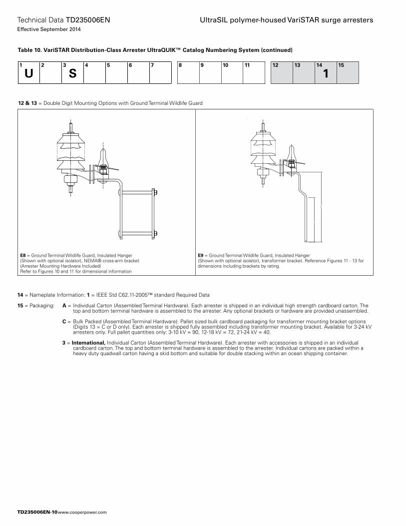
14 = Nameplate Information: 1 = IEEE Std C62.11-2005™ standard Required Data
15 = Packaging: A = Individual Carton (Assembled Terminal Hardware). Each arrester is shipped in an individual high strength cardboard carton. The top and bottom terminal hardware is assembled to the arrester. Any optional brackets or hardware are provided unassembled.
C = Bulk Packed (Assembled Terminal Hardware). Pallet sized bulk cardboard packaging for transformer mounting bracket options (Digits 13 = C or D only). Each arrester is shipped fully assembled including transformer mounting bracket. Available for 3-24 kV arresters only. Full pallet quantities only: 3-10 kV = 90, 12-18 kV = 72, 21-24 kV = 40.
3 = International, Individual Carton (Assembled Terminal Hardware). Each arrester with accessories is shipped in an individual cardboard carton. The top and bottom terminal hardware is assembled to the arrester. Individual cartons are packed within a heavy duty quadwall carton having a skid bottom and suitable for double stacking within an ocean shipping container.
Table 10. VariSTAR Distribution-Class Arrester UltraQUIK™ Catalog Numbering System (continued)
1
U2 3
S4 5 6 7 8 9 10 11 12 13 14
115
12 & 13 = Double Digit Mounting Options with Ground Terminal Wildlife Guard
E8 = Ground Terminal Wildlife Guard, Insulated Hanger(Shown with optional isolator), NEMA® cross-arm bracket (Arrester Mounting Hardware Included)Refer to Figures 10 and 11 for dimensional information
E9 = Ground Terminal Wildlife Guard, Insulated Hanger (Shown with optional isolator), transformer bracket. Reference Figures 11 - 13 for dimensions including brackets by rating.
TD235006EN-10
Technical Data TD235006ENEffective September 2014
UltraSIL polymer-housed VariSTAR surge arresters
www.cooperpower.com
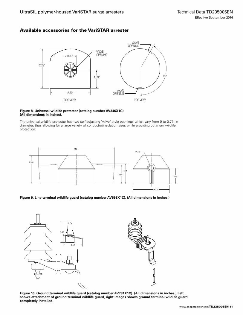
Figure 8. Universal wildlife protector (catalog number AV346X1C). (All dimensions in inches).
The universal wildlife protector has two self-adjusting "valve" style openings which vary from 0 to 0.75" in diameter, thus allowing for a large variety of conductor/insulation sizes while providing optimum wildlife protection.
Available accessories for the VariSTAR arrester
0.80"
2.50"
1.03"
2.22"
VALVEOPENING
VALVEOPENING
VALVEOPENING
SIDE VIEW TOP VIEW
152
Figure 9. Line terminal wildlife guard (catalog number AV698X1C). (All dimensions in inches.)
Figure 10. Ground terminal wildlife guard (catalog number AV731X1C). (All dimensions in inches.) Left shows attachment of ground terminal wildlife guard, right images shows ground terminal wildlife guard completely installed.
TD235006EN-11
Technical Data TD235006ENEffective September 2014
UltraSIL polymer-housed VariSTAR surge arresters
www.cooperpower.com
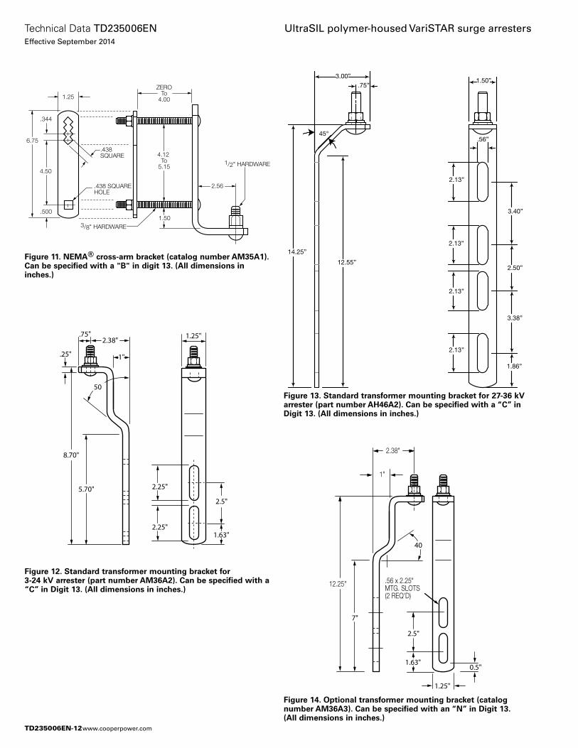
Figure 11. NEMA® cross-arm bracket (catalog number AM35A1). Can be specified with a "B" in digit 13. (All dimensions in inches.)
Figure 12. Standard transformer mounting bracket for 3-24 kV arrester (part number AM36A2). Can be specified with a “C” in Digit 13. (All dimensions in inches.)
2.38"
.25"
.75"
1"
8.70"
5.70"
1.63"
2.25"
50
2.5"
2.25"
1.25"
Figure 13. Standard transformer mounting bracket for 27-36 kV arrester (part number AH46A2). Can be specified with a “C” in Digit 13. (All dimensions in inches.)
3.00”.75”
45°
14.25”
12.55”
2.13”
2.13”
2.13”
2.13”
.56”
3.40”
2.50”
3.38”
1.86”
1.50”
Figure 14. Optional transformer mounting bracket (catalog number AM36A3). Can be specified with an “N” in Digit 13. (All dimensions in inches.)
2.38"
1"
12.25"
7"
1.63"
2.5"
40
0.5"
.56 x 2.25"MTG. SLOTS(2 REQ'D)
1.25"
ZEROTo
4.00
4.12 To
5.15
6.75
2.56
4.50
.344
1.25
.438SQUARE
.438 SQUAREHOLE
.5001.50
3/8" HARDWARE
1/2" HARDWARE
TD235006EN-12
Technical Data TD235006ENEffective September 2014
UltraSIL polymer-housed VariSTAR surge arresters
www.cooperpower.com
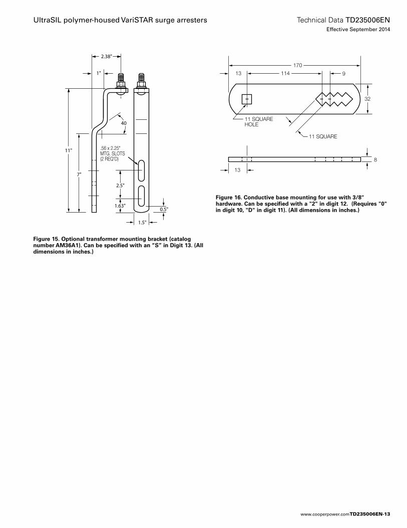
Figure 15. Optional transformer mounting bracket (catalog number AM36A1). Can be specified with an “S” in Digit 13. (All dimensions in inches.)
2.38"
1"
11"
7"
1.63"
2.5"
40
0.5"
.56 x 2.25"MTG. SLOTS(2 REQ'D)
1.5"
114
11 SQUARE
11 SQUAREHOLE
13
13
8
170
9
114
(2) 13 mm O
13
8
32
32
170
13
Figure 16. Conductive base mounting for use with 3/8" hardware. Can be specified with a "2" in digit 12. (Requires "0" in digit 10, "D" in digit 11). (All dimensions in inches.)
TD235006EN-13
Technical Data TD235006ENEffective September 2014
UltraSIL polymer-housed VariSTAR surge arresters
www.cooperpower.com
Additional information• S235-35-1, ANSI® IEEE® UltraSIL Housed Distribution-Class MOV
Arrester Installation Instructions• S235-35-2, ANSI® IEEE® UltraSIL Housed Distribution-Class MOV
BPL Coupler Installation• S235-35-3, ANSI® IEEE® UltraSIL Housed Distribution-Class MOV
BPL Coupler Installation Instructions• 95062, ANSI® IEEE ® UltraSIL Polymer-Housed VariSTAR Normal-
Duty, Heavy-Duty and Riser Pole Distribution-Class Arrester Certified Test Report
• B235-08022, Superior Protection for Arresters and Wildlife
TD235006EN-14
Technical Data TD235006ENEffective September 2014
UltraSIL polymer-housed VariSTAR surge arresters
www.cooperpower.com
TD235006EN-15
Technical Data TD235006ENEffective September 2014
UltraSIL polymer-housed VariSTAR surge arresters
www.cooperpower.com
Eaton, Cooper Power Systems, VariSTAR, UltraSIL, and UltraQUIK are valuable trademarks of Eaton in the U.S. and other countries. You are not permitted to use the these trademarks without the prior written consent of Eaton.IEEE Std C62.11™-2005 and Std C62.22™ standards are trademarks of the Institute of Electrical and Electronics Engineers, Inc., (IEEE). This publication is not endorsed or approved by the IEEE.IEEE® is a registered trademark of the Institute of Electrical and Electronics Engineers, Inc.ANSI® is a registered trademark of the American National Standards Institute.NEMA® is a registered trademark of the National Electrical Manufacturers Association.
UltraSIL polymer-housed VariSTAR surge arresters
Eaton1000 Eaton BoulevardCleveland, OH 44122United StatesEaton.com
Eaton’s Cooper Power Systems Business2300 Badger DriveWaukesha, WI 53188United StatesCooperpower.com
© 2014 EatonAll Rights ReservedPrinted in USAPublication No. TD235006EN
Technical Data TD235006ENEffective September 2014
For Eaton’s Cooper Power Systems surge arrester product information call 1-877-277-4636 or visit: www.cooperpower.com.
TD235006EN-16
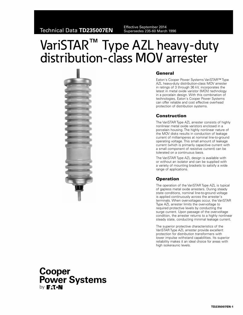
GeneralEaton's Cooper Power Systems VariSTAR™ Type AZL heavy-duty distribution-class MOV arrester in ratings of 3 through 36 kV, incorporates the latest in metal oxide varistor (MOV) technology in a porcelain design. With this combination of technologies, Eaton's Cooper Power Systems can offer reliable and cost effective overhead protection of distribution systems.
ConstructionThe VariSTAR Type AZL arrester consists of highly nonlinear metal oxide varistors enclosed in a porcelain housing. The highly nonlinear nature of the MOV disks results in conduction of leakage current of milliamperes at nominal line-to-ground operating voltage. This small amount of leakage current (which is primarily capacitive current with a small component of resistive current) can be tolerated on a continuous basis.
The VariSTAR Type AZL design is available with or without an isolator and can be supplied with a variety of mounting brackets to satisfy a wide range of applications.
Operation The operation of the VariSTAR Type AZL is typical of gapless metal oxide arresters. During steady state conditions, nominal line-to-ground voltage is applied continuously across the arrester‘s terminals. When overvoltages occur, the VariSTAR Type AZL arrester limits the overvoltage to required protective levels by conducting the surge current. Upon passage of the overvoltage condition, the arrester returns to a highly nonlinear steady state, conducting minimal leakage current.
The superior protective characteristics of the VariSTAR Type AZL arrester provide excellent protection for distribution transformers with lower impulse withstand capabilities. Its superior reliability makes it an ideal choice for areas with high isokeraunic levels.
VariSTAR™ Type AZL heavy-duty distribution-class MOV arrester
TD235007EN-1
Technical Data TD235007ENEffective September 2014Supersedes 235-60 March 1996

Features and detailed description Production testsA complete production test program ensures a quality product. Each VariSTAR metal oxide varistor receives a series of electrical tests. Quality is further ensured by a series of destructive tests performed on every batch of varistors. Listed are the tests that are performed on the varistors:• 100% Physical Inspection• 100% Discharge Voltage Test• 100% V1mA/cm2
• 100% Leakage Current at 80% of V1mA/cm2 Voltage
• Batch High-current, Short-duration Test• Batch Thermal Stability Test• Batch Disk Aging Test
Each VariSTAR Type AZL arrester must pass the following production tests:• 100% Physical Inspection• 100% Vacuum over Fluid Seal Test• 100% Leakage Current Test• 100% RIV Test
StandardsThe VariSTAR Type AZL arrester complies with the latest revision of IEEE Std C62.11™-1987 standard “IEEE Standard for Metal Oxide Surge Arresters for AC Power Circuits”.
General application recommendationsThe rating of an arrester is the power frequency line-to-ground voltage at which the arrester is designed to pass an operating duty-cycle test. Table 1 provides a general application guide for the selection of the proper arrester rating for a given system voltage and system grounding configuration.
Eaton's Cooper Power Systems application engineers are available to make recommendations. The following information is normally required:
1. System maximum operating voltage.
2. System grounding conditions.
A. For four-wire circuits, grounding conditions depend upon whether the system is multi-grounded, whether it has a neutral impedance and whether common primary and secondary neutrals are used.
B. For three-wire circuits, grounding conditions depend upon whether the system is solidly grounded at the source, grounded through neutral impedance at the source transformers or ungrounded.
Where unusual conditions exist (high ground resistance, high capacitive load, arc-welding equipment, etc.) the following
Figure 1. Cutaway illustration of VariSTAR AZL arrester.
INSULATING TERMINAL CAP
Polymer cap provides superior wildlife protection.
TOP ELECTRODE
Ensures low resistive contact to MOV disk column.
MOV DISKS
Highly nonlinear metal oxide varistors provide exceptional surge pro-tection.
HEAVY STEEL COIL SPRING
Maintains high pres-sure on disks for effective contact sur-faces; protects from mechanical shock.
COPPER STRAP
Provides a low resistance shunt for surge current discharge.
SOLDERLESS CONNECTORS
Accommodates No. 10 solid through No. 2/0 stranded line and ground leads.
ISOLATOR™ GROUND LEAD DISCONNECTOR
Provides positive isolation and visual identification if arrester becomes damaged internally.
IDENTIFICATION INFORMATION
Convenient reference for arrester type, MCOV, voltage rating and year and quarter of manufacture.
ALUMINUM SPACER
Provides additional length for extended creepage porcelain.
HIGH STRENGTH WET PROCESS GLAZED PORCELAIN
Withstands thermal and mechanical shocks; excellent washing character-istics; provides high creepage distance above and below the hanger bracket.
TD235007EN-2
Technical Data TD235007ENEffective September 2014
VariSTAR Type AZL heavy-duty distribution-class MOV arrester
www.cooperpower.com
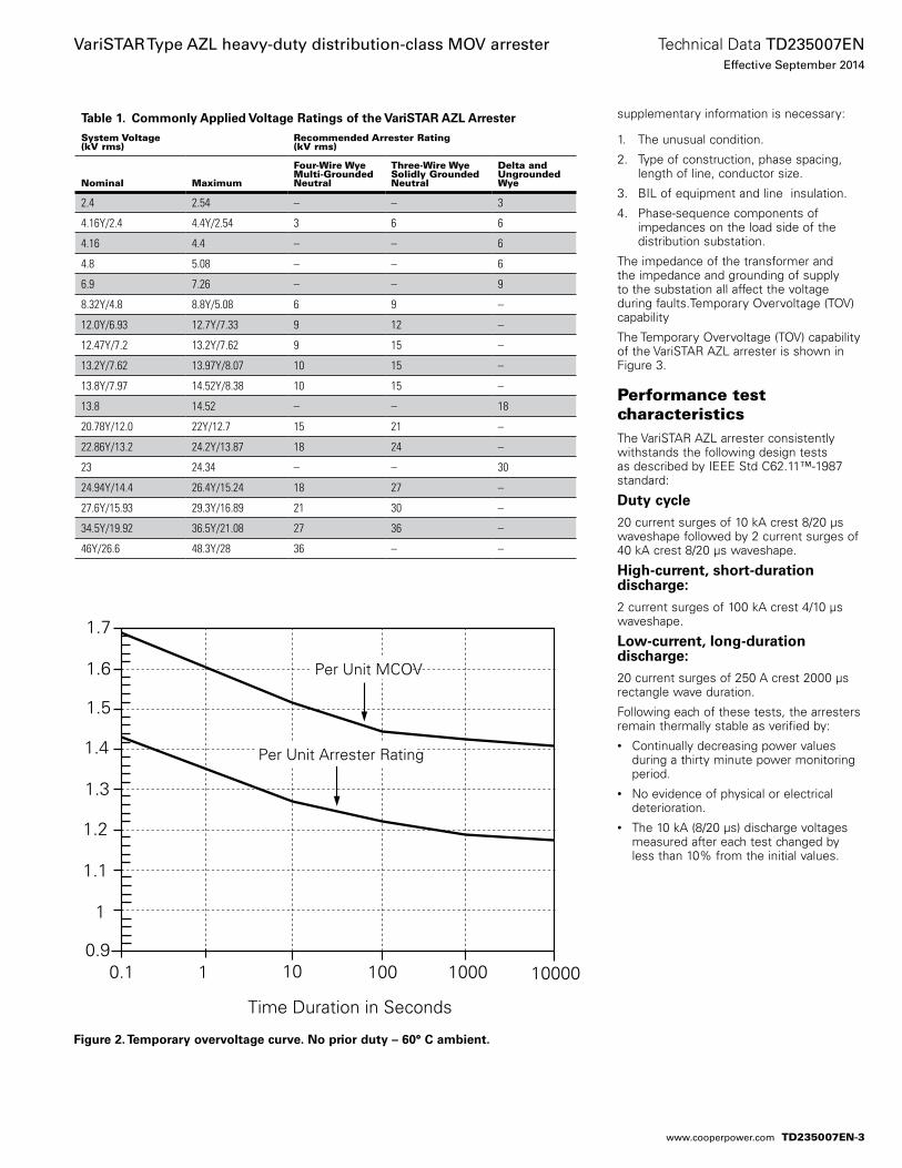
supplementary information is necessary:
1. The unusual condition.
2. Type of construction, phase spacing, length of line, conductor size.
3. BIL of equipment and line insulation.
4. Phase-sequence components of impedances on the load side of the distribution substation.
The impedance of the transformer and the impedance and grounding of supply to the substation all affect the voltage during faults.Temporary Overvoltage (TOV) capability
The Temporary Overvoltage (TOV) capability of the VariSTAR AZL arrester is shown in Figure 3.
Performance test characteristicsThe VariSTAR AZL arrester consistently withstands the following design tests as described by IEEE Std C62.11™-1987 standard:
Duty cycle20 current surges of 10 kA crest 8/20 µs waveshape followed by 2 current surges of 40 kA crest 8/20 µs waveshape.
High-current, short-duration discharge:2 current surges of 100 kA crest 4/10 µs waveshape.
Low-current, long-duration discharge:20 current surges of 250 A crest 2000 µs rectangle wave duration.
Following each of these tests, the arresters remain thermally stable as verified by:• Continually decreasing power values
during a thirty minute power monitoring period.
• No evidence of physical or electrical deterioration.
• The 10 kA (8/20 µs) discharge voltages measured after each test changed by less than 10% from the initial values.
Figure 2. Temporary overvoltage curve. No prior duty – 60° C ambient.
Table 1. Commonly Applied Voltage Ratings of the VariSTAR AZL Arrester
System Voltage(kV rms)
Recommended Arrester Rating(kV rms)
Nominal Maximum
Four-Wire WyeMulti-GroundedNeutral
Three-Wire WyeSolidly GroundedNeutral
Delta andUngroundedWye
2.4 2.54 – – 3
4.16Y/2.4 4.4Y/2.54 3 6 6
4.16 4.4 – – 6
4.8 5.08 – – 6
6.9 7.26 – – 9
8.32Y/4.8 8.8Y/5.08 6 9 –
12.0Y/6.93 12.7Y/7.33 9 12 –
12.47Y/7.2 13.2Y/7.62 9 15 –
13.2Y/7.62 13.97Y/8.07 10 15 –
13.8Y/7.97 14.52Y/8.38 10 15 –
13.8 14.52 – – 18
20.78Y/12.0 22Y/12.7 15 21 –
22.86Y/13.2 24.2Y/13.87 18 24 –
23 24.34 – – 30
24.94Y/14.4 26.4Y/15.24 18 27 –
27.6Y/15.93 29.3Y/16.89 21 30 –
34.5Y/19.92 36.5Y/21.08 27 36 –
46Y/26.6 48.3Y/28 36 – –
Time Duration in Seconds
10 100 100010.9
10000
1
1.1
1.2
1.3
1.4
1.5
1.6
1.7
Per Unit Arrester Rating
Per Unit MCOV
0.1
TD235007EN-3
Technical Data TD235007ENEffective September 2014
VariSTAR Type AZL heavy-duty distribution-class MOV arrester
www.cooperpower.com
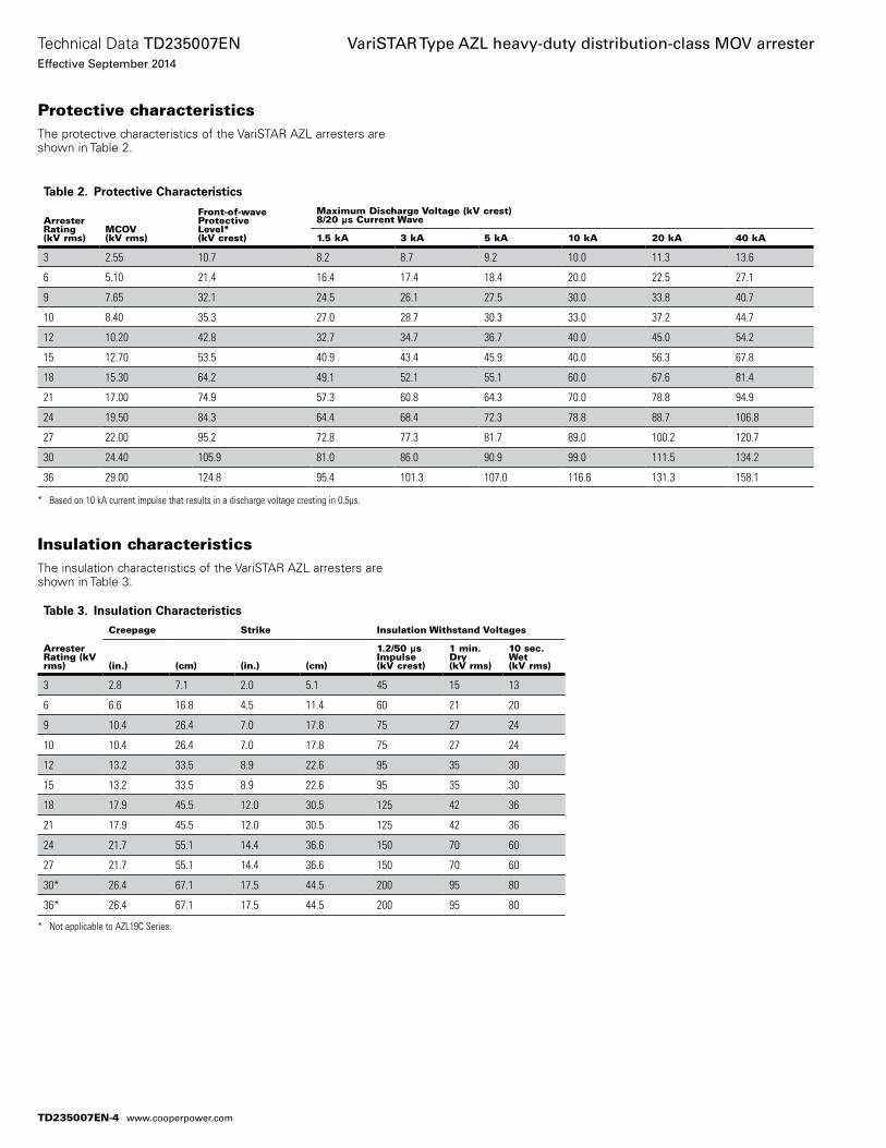
Protective characteristicsThe protective characteristics of the VariSTAR AZL arresters are shown in Table 2.
Insulation characteristicsThe insulation characteristics of the VariSTAR AZL arresters are shown in Table 3.
Table 2. Protective Characteristics
ArresterRating(kV rms)
MCOV(kV rms)
Front-of-waveProtectiveLevel*(kV crest)
Maximum Discharge Voltage (kV crest)8/20 µs Current Wave
1.5 kA 3 kA 5 kA 10 kA 20 kA 40 kA
3 2.55 10.7 8.2 8.7 9.2 10.0 11.3 13.6
6 5.10 21.4 16.4 17.4 18.4 20.0 22.5 27.1
9 7.65 32.1 24.5 26.1 27.5 30.0 33.8 40.7
10 8.40 35.3 27.0 28.7 30.3 33.0 37.2 44.7
12 10.20 42.8 32.7 34.7 36.7 40.0 45.0 54.2
15 12.70 53.5 40.9 43.4 45.9 40.0 56.3 67.8
18 15.30 64.2 49.1 52.1 55.1 60.0 67.6 81.4
21 17.00 74.9 57.3 60.8 64.3 70.0 78.8 94.9
24 19.50 84.3 64.4 68.4 72.3 78.8 88.7 106.8
27 22.00 95.2 72.8 77.3 81.7 89.0 100.2 120.7
30 24.40 105.9 81.0 86.0 90.9 99.0 111.5 134.2
36 29.00 124.8 95.4 101.3 107.0 116.6 131.3 158.1
* Based on 10 kA current impulse that results in a discharge voltage cresting in 0.5µs.
Table 3. Insulation Characteristics
Arrester Rating (kV rms)
Creepage Strike Insulation Withstand Voltages
(in.) (cm) (in.) (cm)
1.2/50 μs Impulse (kV crest)
1 min. Dry (kV rms)
10 sec. Wet (kV rms)
3 2.8 7.1 2.0 5.1 45 15 13
6 6.6 16.8 4.5 11.4 60 21 20
9 10.4 26.4 7.0 17.8 75 27 24
10 10.4 26.4 7.0 17.8 75 27 24
12 13.2 33.5 8.9 22.6 95 35 30
15 13.2 33.5 8.9 22.6 95 35 30
18 17.9 45.5 12.0 30.5 125 42 36
21 17.9 45.5 12.0 30.5 125 42 36
24 21.7 55.1 14.4 36.6 150 70 60
27 21.7 55.1 14.4 36.6 150 70 60
30* 26.4 67.1 17.5 44.5 200 95 80
36* 26.4 67.1 17.5 44.5 200 95 80
* Not applicable to AZL19C Series.
TD235007EN-4
Technical Data TD235007ENEffective September 2014
VariSTAR Type AZL heavy-duty distribution-class MOV arrester
www.cooperpower.com
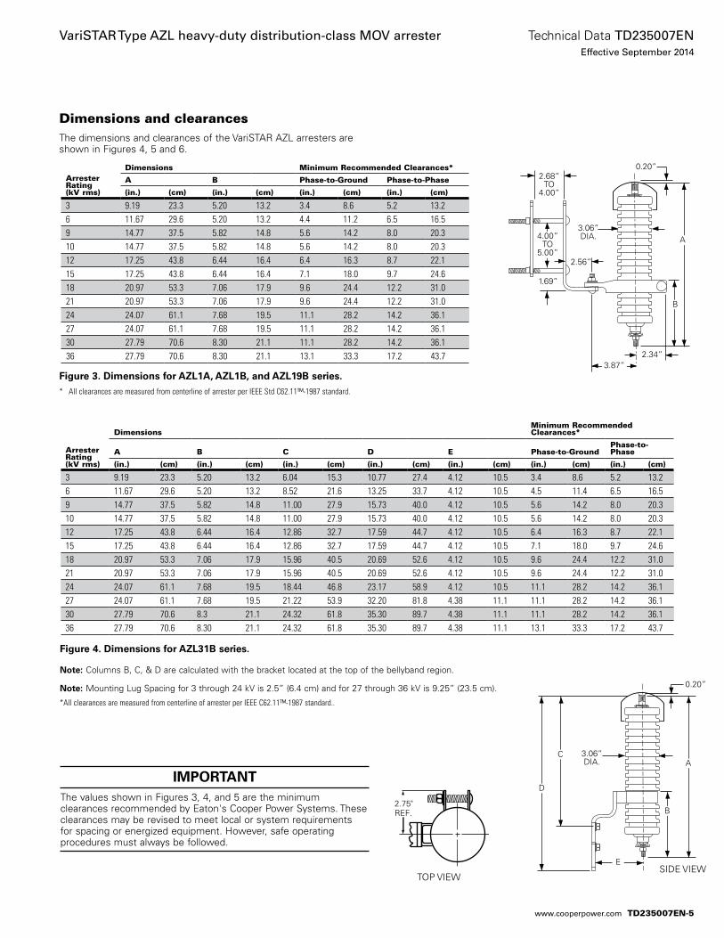
Dimensions and clearancesThe dimensions and clearances of the VariSTAR AZL arresters are shown in Figures 4, 5 and 6.
Figure 3. Dimensions for AZL1A, AZL1B, and AZL19B series.* All clearances are measured from centerline of arrester per IEEE Std C62.11™-1987 standard.
Arrester Rating (kV rms)
DimensionsMinimum Recommended Clearances*
A B C D E Phase-to-GroundPhase-to-Phase
(in.) (cm) (in.) (cm) (in.) (cm) (in.) (cm) (in.) (cm) (in.) (cm) (in.) (cm)
3 9.19 23.3 5.20 13.2 6.04 15.3 10.77 27.4 4.12 10.5 3.4 8.6 5.2 13.26 11.67 29.6 5.20 13.2 8.52 21.6 13.25 33.7 4.12 10.5 4.5 11.4 6.5 16.59 14.77 37.5 5.82 14.8 11.00 27.9 15.73 40.0 4.12 10.5 5.6 14.2 8.0 20.310 14.77 37.5 5.82 14.8 11.00 27.9 15.73 40.0 4.12 10.5 5.6 14.2 8.0 20.312 17.25 43.8 6.44 16.4 12.86 32.7 17.59 44.7 4.12 10.5 6.4 16.3 8.7 22.115 17.25 43.8 6.44 16.4 12.86 32.7 17.59 44.7 4.12 10.5 7.1 18.0 9.7 24.618 20.97 53.3 7.06 17.9 15.96 40.5 20.69 52.6 4.12 10.5 9.6 24.4 12.2 31.021 20.97 53.3 7.06 17.9 15.96 40.5 20.69 52.6 4.12 10.5 9.6 24.4 12.2 31.024 24.07 61.1 7.68 19.5 18.44 46.8 23.17 58.9 4.12 10.5 11.1 28.2 14.2 36.127 24.07 61.1 7.68 19.5 21.22 53.9 32.20 81.8 4.38 11.1 11.1 28.2 14.2 36.130 27.79 70.6 8.3 21.1 24.32 61.8 35.30 89.7 4.38 11.1 11.1 28.2 14.2 36.136 27.79 70.6 8.30 21.1 24.32 61.8 35.30 89.7 4.38 11.1 13.1 33.3 17.2 43.7
Figure 4. Dimensions for AZL31B series.
ote:N Columns B, C, & D are calculated with the bracket located at the top of the bellyband region.
ote:N Mounting Lug Spacing for 3 through 24 kV is 2.5” (6.4 cm) and for 27 through 36 kV is 9.25” (23.5 cm).
*All clearances are measured from centerline of arrester per IEEE C62.11™-1987 standard..
Arrester Rating (kV rms)
Dimensions Minimum Recommended Clearances*
A B Phase-to-Ground Phase-to-Phase
(in.) (cm) (in.) (cm) (in.) (cm) (in.) (cm)
3 9.19 23.3 5.20 13.2 3.4 8.6 5.2 13.26 11.67 29.6 5.20 13.2 4.4 11.2 6.5 16.59 14.77 37.5 5.82 14.8 5.6 14.2 8.0 20.310 14.77 37.5 5.82 14.8 5.6 14.2 8.0 20.312 17.25 43.8 6.44 16.4 6.4 16.3 8.7 22.115 17.25 43.8 6.44 16.4 7.1 18.0 9.7 24.618 20.97 53.3 7.06 17.9 9.6 24.4 12.2 31.021 20.97 53.3 7.06 17.9 9.6 24.4 12.2 31.024 24.07 61.1 7.68 19.5 11.1 28.2 14.2 36.127 24.07 61.1 7.68 19.5 11.1 28.2 14.2 36.130 27.79 70.6 8.30 21.1 11.1 28.2 14.2 36.136 27.79 70.6 8.30 21.1 13.1 33.3 17.2 43.7
2.75"REF.
TOP VIEW
A
B
1.69”
2.34”
2.56”
3.06” DIA.
0.20”
4.00”TO
5.00”
2.68”TO
4.00”
3.87”
A
0.20”
3.06”DIA.
C
D
B
ESIDE VIEW
IMPORTANTThe values shown in Figures 3, 4, and 5 are the minimum clearances recommended by Eaton's Cooper Power Systems. These clearances may be revised to meet local or system requirements for spacing or energized equipment. However, safe operating procedures must always be followed.
TD235007EN-5
Technical Data TD235007ENEffective September 2014
VariSTAR Type AZL heavy-duty distribution-class MOV arrester
www.cooperpower.com
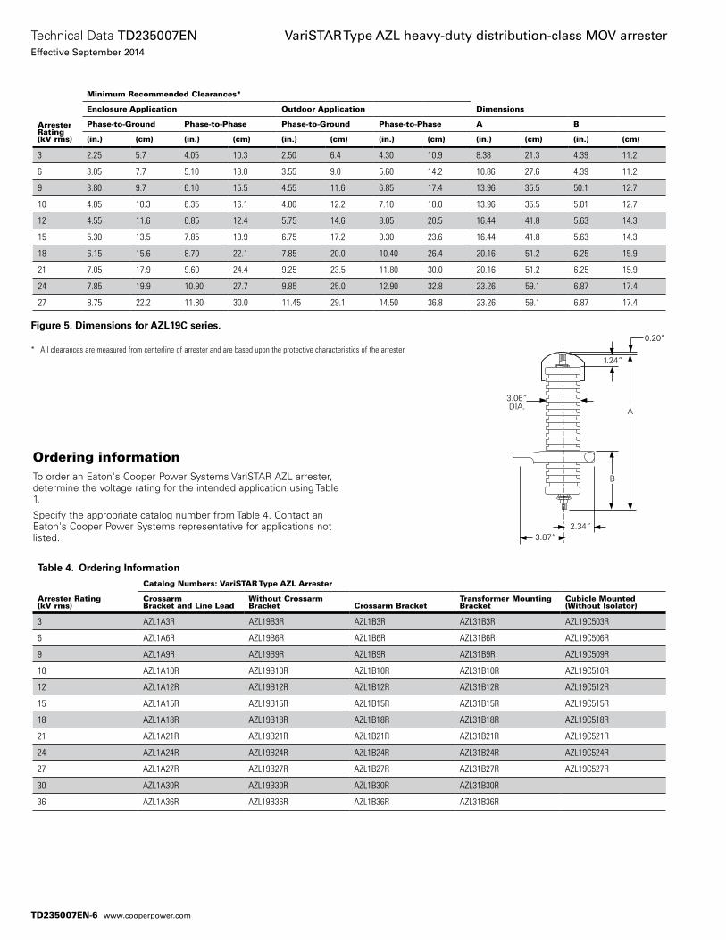
ArresterRating(kV rms)
Minimum Recommended Clearances*
DimensionsEnclosure Application Outdoor Application
Phase-to-Ground Phase-to-Phase Phase-to-Ground Phase-to-Phase A B
(in.) (cm) (in.) (cm) (in.) (cm) (in.) (cm) (in.) (cm) (in.) (cm)
3 2.25 5.7 4.05 10.3 2.50 6.4 4.30 10.9 8.38 21.3 4.39 11.2
6 3.05 7.7 5.10 13.0 3.55 9.0 5.60 14.2 10.86 27.6 4.39 11.2
9 3.80 9.7 6.10 15.5 4.55 11.6 6.85 17.4 13.96 35.5 50.1 12.7
10 4.05 10.3 6.35 16.1 4.80 12.2 7.10 18.0 13.96 35.5 5.01 12.7
12 4.55 11.6 6.85 12.4 5.75 14.6 8.05 20.5 16.44 41.8 5.63 14.3
15 5.30 13.5 7.85 19.9 6.75 17.2 9.30 23.6 16.44 41.8 5.63 14.3
18 6.15 15.6 8.70 22.1 7.85 20.0 10.40 26.4 20.16 51.2 6.25 15.9
21 7.05 17.9 9.60 24.4 9.25 23.5 11.80 30.0 20.16 51.2 6.25 15.9
24 7.85 19.9 10.90 27.7 9.85 25.0 12.90 32.8 23.26 59.1 6.87 17.4
27 8.75 22.2 11.80 30.0 11.45 29.1 14.50 36.8 23.26 59.1 6.87 17.4
Figure 5. Dimensions for AZL19C series.
* All clearances are measured from centerline of arrester and are based upon the protective characteristics of the arrester.
Ordering informationTo order an Eaton's Cooper Power Systems VariSTAR AZL arrester, determine the voltage rating for the intended application using Table 1.
Specify the appropriate catalog number from Table 4. Contact an Eaton's Cooper Power Systems representative for applications not listed.
Table 4. Ordering Information
Arrester Rating(kV rms)
Catalog Numbers: VariSTAR Type AZL Arrester
CrossarmBracket and Line Lead
Without CrossarmBracket Crossarm Bracket
Transformer MountingBracket
Cubicle Mounted(Without Isolator)
3 AZL1A3R AZL19B3R AZL1B3R AZL31B3R AZL19C503R
6 AZL1A6R AZL19B6R AZL1B6R AZL31B6R AZL19C506R
9 AZL1A9R AZL19B9R AZL1B9R AZL31B9R AZL19C509R
10 AZL1A10R AZL19B10R AZL1B10R AZL31B10R AZL19C510R
12 AZL1A12R AZL19B12R AZL1B12R AZL31B12R AZL19C512R
15 AZL1A15R AZL19B15R AZL1B15R AZL31B15R AZL19C515R
18 AZL1A18R AZL19B18R AZL1B18R AZL31B18R AZL19C518R
21 AZL1A21R AZL19B21R AZL1B21R AZL31B21R AZL19C521R
24 AZL1A24R AZL19B24R AZL1B24R AZL31B24R AZL19C524R
27 AZL1A27R AZL19B27R AZL1B27R AZL31B27R AZL19C527R
30 AZL1A30R AZL19B30R AZL1B30R AZL31B30R
36 AZL1A36R AZL19B36R AZL1B36R AZL31B36R
A
B
2.34”
3.06” DIA.
0.20”
1.24”
3.87”
TD235007EN-6
Technical Data TD235007ENEffective September 2014
VariSTAR Type AZL heavy-duty distribution-class MOV arrester
www.cooperpower.com
TD235007EN-7
Technical Data TD235007ENEffective September 2014
VariSTAR Type AZL heavy-duty distribution-class MOV arrester
www.cooperpower.com
This page is intentionally left blank.
Eaton, Cooper Power Systems, Isolator, and VariSTAR are valuable trademarks of Eaton in the U.S. and other countries. You are not per-mitted to use the these trademarks without the prior written consent of Eaton.IEEE Std C62.11™-1987 standard is a trademark of the Institute of Electrical and Electronics Engineers, Inc., (IEEE). This pub-lication is not endorsed or approved by the IEEE.
VariSTAR Type AZL heavy-duty distribution-class MOV arrester
Eaton1000 Eaton BoulevardCleveland, OH 44122United StatesEaton.com
Eaton’s Cooper Power Systems Business2300 Badger DriveWaukesha, WI 53188United StatesCooperpower.com
© 2014 EatonAll Rights ReservedPrinted in USAPublication No. TD235007EN
Technical Data TD235007ENEffective September 2014
For Eaton’s Cooper Power Systems VariSTAR AZL surge arrester product information call 1-877-277-4636 or visit: www.cooperpower.com.
TD235007EN-8
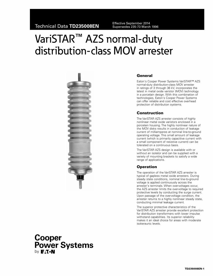
VariSTAR™ AZS normal-duty distribution-class MOV arrester
GeneralEaton's Cooper Power Systems VariSTAR™ AZS normal-duty distribution-class MOV arrester in ratings of 3 through 36 kV, incorporates the latest in metal oxide varistor (MOV) technology in a porcelain design. With this combination of technologies, Eaton's Cooper Power Systems can offer reliable and cost effective overhead protection of distribution systems.
ConstructionThe VariSTAR AZS arrester consists of highly nonlinear metal oxide varistors enclosed in a porcelain housing. The highly nonlinear nature of the MOV disks results in conduction of leakage current of milliamperes at nominal line-to-ground operating voltage. This small amount of leakage current (which is primarily capacitive current with a small component of resistive current) can be tolerated on a continuous basis.
The VariSTAR AZS design is available with or without an isolator and can be supplied with a variety of mounting brackets to satisfy a wide range of applications.
OperationThe operation of the VariSTAR AZS arrester is typical of gapless metal oxide arresters. During steady state conditions, nominal line-to-ground voltage is applied continuously across the arrester‘s terminals. When overvoltages occur, the AZS arrester limits the overvoltage to required protective levels by conducting the surge current. Upon passage of the overvoltage condition, the arrester returns to a highly nonlinear steady state, conducting minimal leakage current.
The superior protective characteristics of the VariSTAR AZS arrester provide excellent protection for distribution transformers with lower impulse withstand capabilities. Its superior reliability makes it an ideal choice for areas with moderate isokeraunic levels.
TD235008EN-1
Technical Data TD235008ENEffective September 2014Supersedes 235-73 March 1996
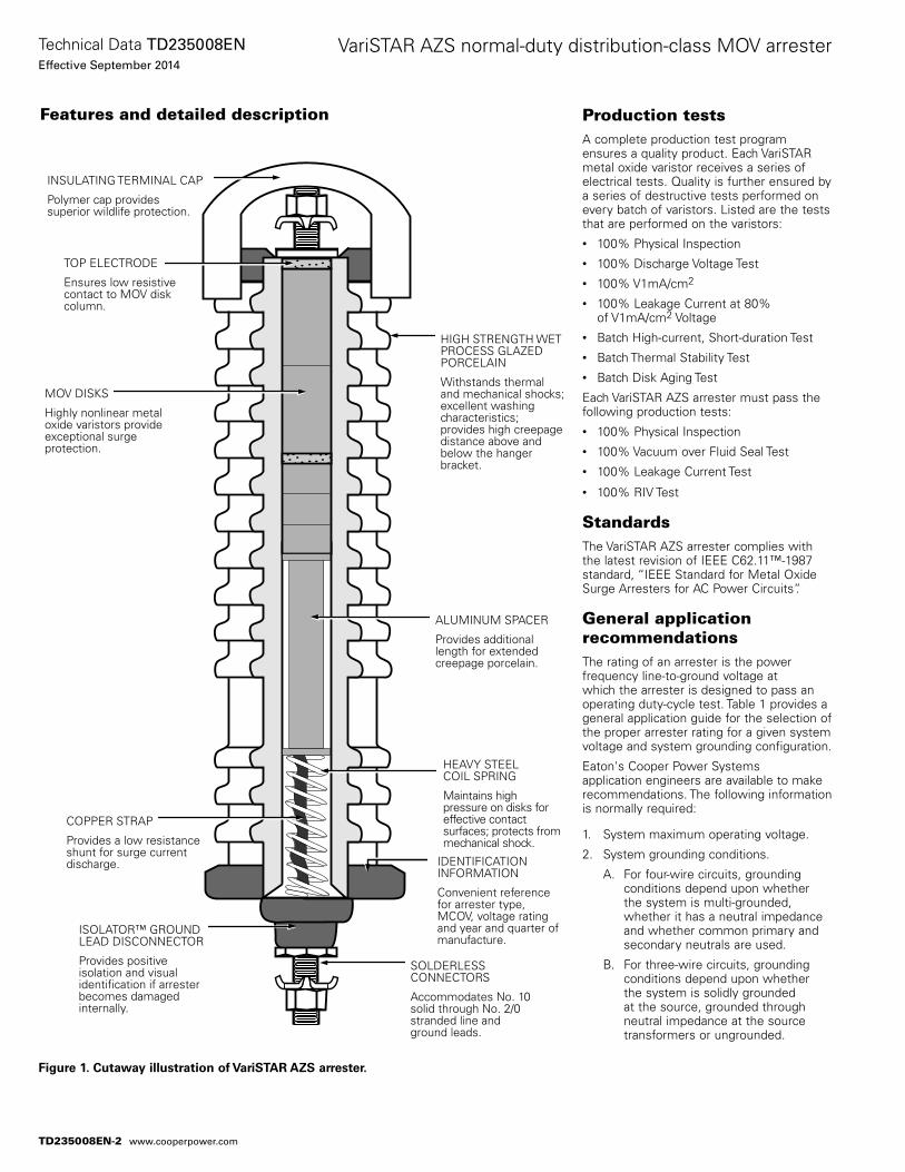
Features and detailed description Production testsA complete production test program ensures a quality product. Each VariSTAR metal oxide varistor receives a series of electrical tests. Quality is further ensured by a series of destructive tests performed on every batch of varistors. Listed are the tests that are performed on the varistors:• 100% Physical Inspection• 100% Discharge Voltage Test• 100% V1mA/cm2
• 100% Leakage Current at 80% of V1mA/cm2 Voltage
• Batch High-current, Short-duration Test• Batch Thermal Stability Test• Batch Disk Aging Test
Each VariSTAR AZS arrester must pass the following production tests:• 100% Physical Inspection• 100% Vacuum over Fluid Seal Test• 100% Leakage Current Test
• 100% RIV Test
StandardsThe VariSTAR AZS arrester complies with the latest revision of IEEE C62.11™-1987 standard, “IEEE Standard for Metal Oxide Surge Arresters for AC Power Circuits”.
General application recommendationsThe rating of an arrester is the power frequency line-to-ground voltage at which the arrester is designed to pass an operating duty-cycle test. Table 1 provides a general application guide for the selection of the proper arrester rating for a given system voltage and system grounding configuration.
Eaton's Cooper Power Systems application engineers are available to make recommendations. The following information is normally required:
1. System maximum operating voltage.
2. System grounding conditions.
A. For four-wire circuits, grounding conditions depend upon whether the system is multi-grounded, whether it has a neutral impedance and whether common primary and secondary neutrals are used.
B. For three-wire circuits, grounding conditions depend upon whether the system is solidly grounded at the source, grounded through neutral impedance at the source transformers or ungrounded.
Figure 1. Cutaway illustration of VariSTAR AZS arrester.
INSULATING TERMINAL CAP
Polymer cap provides superior wildlife protection.
TOP ELECTRODE
Ensures low resistive contact to MOV disk column.
MOV DISKS
Highly nonlinear metal oxide varistors provide exceptional surge protection.
HEAVY STEEL COIL SPRING
Maintains high pressure on disks for effective contact surfaces; protects from mechanical shock.
COPPER STRAP
Provides a low resistance shunt for surge current discharge.
SOLDERLESS CONNECTORS
Accommodates No. 10 solid through No. 2/0 stranded line and ground leads.
ISOLATOR™ GROUND LEAD DISCONNECTOR
Provides positive isolation and visual identification if arrester becomes damaged internally.
IDENTIFICATION INFORMATION
Convenient reference for arrester type, MCOV, voltage rating and year and quarter of manufacture.
ALUMINUM SPACER
Provides additional length for extended creepage porcelain.
HIGH STRENGTH WET PROCESS GLAZED PORCELAIN
Withstands thermal and mechanical shocks; excellent washing characteristics; provides high creepage distance above and below the hanger bracket.
TD235008EN-2
Technical Data TD235008ENEffective September 2014
VariSTAR AZS normal-duty distribution-class MOV arrester
www.cooperpower.com
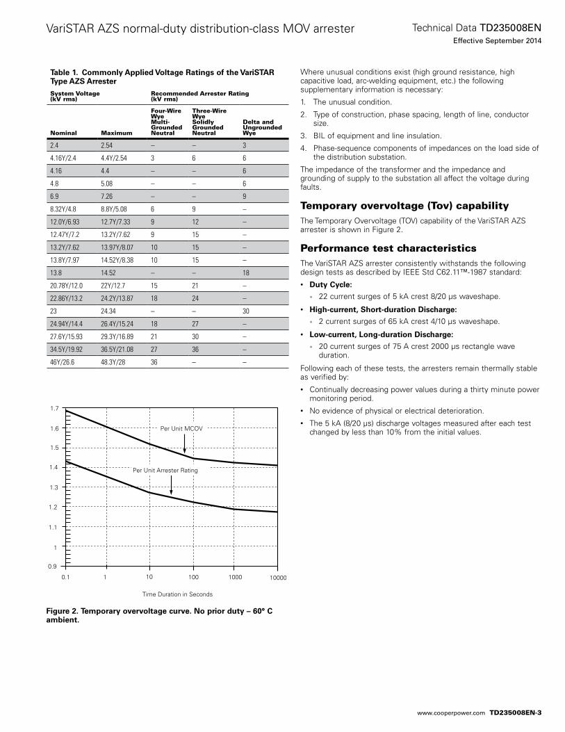
Where unusual conditions exist (high ground resistance, high capacitive load, arc-welding equipment, etc.) the following supplementary information is necessary:
1. The unusual condition.
2. Type of construction, phase spacing, length of line, conductor size.
3. BIL of equipment and line insulation.
4. Phase-sequence components of impedances on the load side of the distribution substation.
The impedance of the transformer and the impedance and grounding of supply to the substation all affect the voltage during faults.
Temporary overvoltage (Tov) capabilityThe Temporary Overvoltage (TOV) capability of the VariSTAR AZS arrester is shown in Figure 2.
Performance test characteristicsThe VariSTAR AZS arrester consistently withstands the following design tests as described by IEEE Std C62.11™-1987 standard:• Duty Cycle:
• 22 current surges of 5 kA crest 8/20 µs waveshape.
• High-current, Short-duration Discharge:
• 2 current surges of 65 kA crest 4/10 µs waveshape.
• Low-current, Long-duration Discharge:
• 20 current surges of 75 A crest 2000 µs rectangle wave duration.
Following each of these tests, the arresters remain thermally stable as verified by:• Continually decreasing power values during a thirty minute power
monitoring period.• No evidence of physical or electrical deterioration.• The 5 kA (8/20 µs) discharge voltages measured after each test
changed by less than 10% from the initial values.
Figure 2. Temporary overvoltage curve. No prior duty – 60° C ambient.
Time Duration in Seconds
10 100 10001
0.9
10000
1
1.1
1.2
1.3
1.4
1.5
1.6
1.7
Per Unit Arrester Rating
Per Unit MCOV
0.1
Table 1. Commonly Applied Voltage Ratings of the VariSTAR Type AZS Arrester
System Voltage(kV rms)
Recommended Arrester Rating(kV rms)
Nominal Maximum
Four-Wire WyeMulti-GroundedNeutral
Three-Wire WyeSolidly GroundedNeutral
Delta andUngroundedWye
2.4 2.54 – – 3
4.16Y/2.4 4.4Y/2.54 3 6 6
4.16 4.4 – – 6
4.8 5.08 – – 6
6.9 7.26 – – 9
8.32Y/4.8 8.8Y/5.08 6 9 –
12.0Y/6.93 12.7Y/7.33 9 12 –
12.47Y/7.2 13.2Y/7.62 9 15 –
13.2Y/7.62 13.97Y/8.07 10 15 –
13.8Y/7.97 14.52Y/8.38 10 15 –
13.8 14.52 – – 18
20.78Y/12.0 22Y/12.7 15 21 –
22.86Y/13.2 24.2Y/13.87 18 24 –
23 24.34 – – 30
24.94Y/14.4 26.4Y/15.24 18 27 –
27.6Y/15.93 29.3Y/16.89 21 30 –
34.5Y/19.92 36.5Y/21.08 27 36 –
46Y/26.6 48.3Y/28 36 – –
TD235008EN-3
Technical Data TD235008ENEffective September 2014
VariSTAR AZS normal-duty distribution-class MOV arrester
www.cooperpower.com
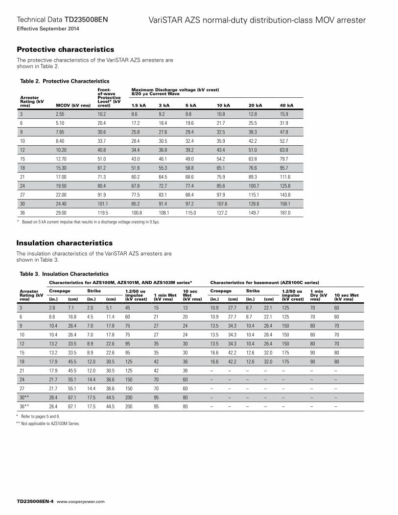
Protective characteristicsThe protective characteristics of the VariSTAR AZS arresters are shown in Table 2.
Insulation characteristicsThe insulation characteristics of the VariSTAR AZS arresters are shown in Table 3.
Table 2. Protective Characteristics
Arrester Rating (kV rms) MCOV (kV rms)
Front-of-wave Protective Level* (kV crest)
Maximum Discharge voltage (kV crest)8/20 μs Current Wave
1.5 kA 3 kA 5 kA 10 kA 20 kA 40 kA
3 2.55 10.2 8.6 9.2 9.8 10.8 12.8 15.9
6 5.10 20.4 17.2 18.4 19.6 21.7 25.5 31.9
9 7.65 30.6 25.8 27.6 29.4 32.5 38.3 47.8
10 8.40 33.7 28.4 30.5 32.4 35.9 42.2 52.7
12 10.20 40.8 34.4 36.8 39.2 43.4 51.0 63.8
15 12.70 51.0 43.0 46.1 49.0 54.2 63.8 79.7
18 15.30 61.2 51.6 55.3 58.8 65.1 76.6 95.7
21 17.00 71.3 60.2 64.5 68.6 75.9 89.3 111.6
24 19.50 80.4 67.8 72.7 77.4 85.6 100.7 125.8
27 22.00 91.9 77.5 83.1 88.4 97.9 115.1 143.8
30 24.40 101.1 85.2 91.4 97.2 107.6 126.6 158.1
36 29.00 119.5 100.8 108.1 115.0 127.2 149.7 187.0
* Based on 5 kA current impulse that results in a discharge voltage cresting in 0.5µs.
Table 3. Insulation Characteristics
Arrester Rating (kV rms)
Characteristics for AZS100M, AZS101M, AND AZS103M series* Characteristics for basemount (AZS100C series)
Creepage Strike 1.2/50 us impulse (kV crest)
1 min Wet (kV rms)
10 sec Wet (kV rms)
Creepage Strike 1.2/50 us impulse (kV crest)
1 min Dry (kV rms)
10 sec Wet (kV rms)(in.) (cm) (in.) (cm) (in.) (cm) (in.) (cm)
3 2.8 7.1 2.0 5.1 45 15 13 10.9 27.7 8.7 22.1 125 70 60
6 6.6 16.8 4.5 11.4 60 21 20 10.9 27.7 8.7 22.1 125 70 60
9 10.4 26.4 7.0 17.8 75 27 24 13.5 34.3 10.4 26.4 150 80 70
10 10.4 26.4 7.0 17.8 75 27 24 13.5 34.3 10.4 26.4 150 80 70
12 13.2 33.5 8.9 22.6 95 35 30 13.5 34.3 10.4 26.4 150 80 70
15 13.2 33.5 8.9 22.6 95 35 30 16.6 42.2 12.6 32.0 175 90 80
18 17.9 45.5 12.0 30.5 125 42 36 16.6 42.2 12.6 32.0 175 90 80
21 17.9 45.5 12.0 30.5 125 42 36 – – – – – – –
24 21.7 55.1 14.4 36.6 150 70 60 – – – – – – –
27 21.7 55.1 14.4 36.6 150 70 60 – – – – – – –
30** 26.4 67.1 17.5 44.5 200 95 80 – – – – – – –
36** 26.4 67.1 17.5 44.5 200 95 80 – – – – – – –
* Refer to pages 5 and 6.
** Not applicable to AZS103M Series.
TD235008EN-4
Technical Data TD235008ENEffective September 2014
VariSTAR AZS normal-duty distribution-class MOV arrester
www.cooperpower.com
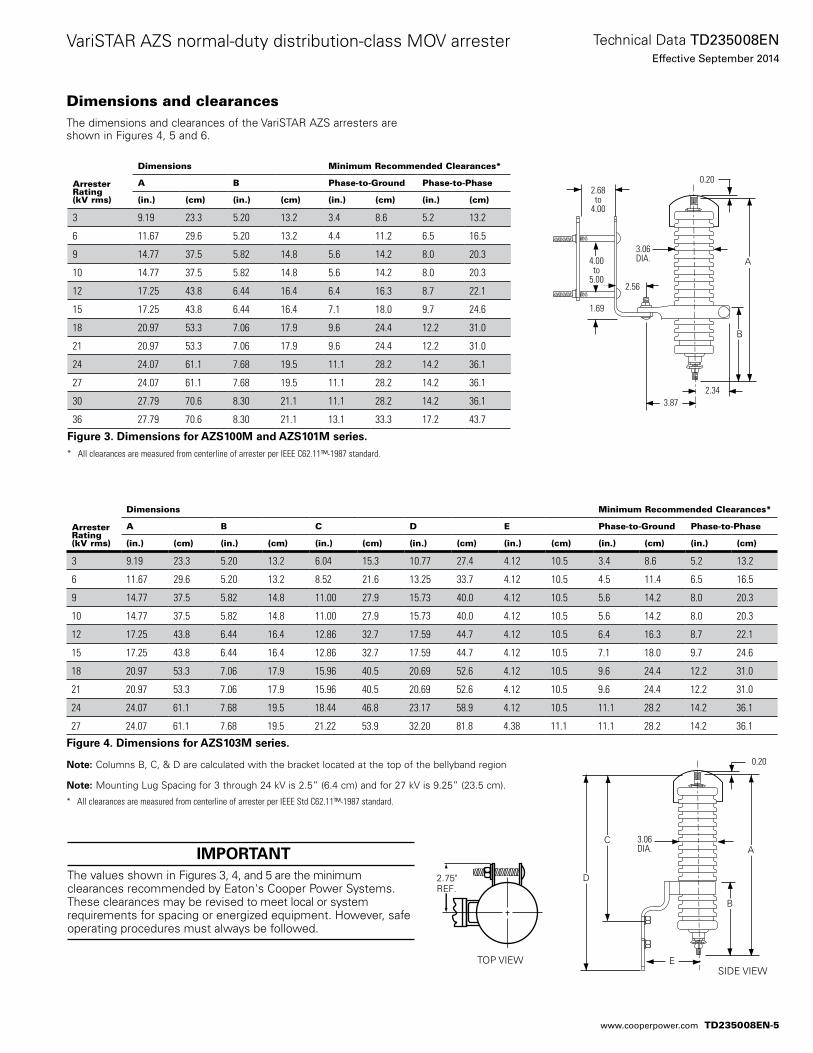
Dimensions and clearancesThe dimensions and clearances of the VariSTAR AZS arresters are shown in Figures 4, 5 and 6.
Arrester Rating (kV rms)
Dimensions Minimum Recommended Clearances*
A B Phase-to-Ground Phase-to-Phase
(in.) (cm) (in.) (cm) (in.) (cm) (in.) (cm)
3 9.19 23.3 5.20 13.2 3.4 8.6 5.2 13.2
6 11.67 29.6 5.20 13.2 4.4 11.2 6.5 16.5
9 14.77 37.5 5.82 14.8 5.6 14.2 8.0 20.3
10 14.77 37.5 5.82 14.8 5.6 14.2 8.0 20.3
12 17.25 43.8 6.44 16.4 6.4 16.3 8.7 22.1
15 17.25 43.8 6.44 16.4 7.1 18.0 9.7 24.6
18 20.97 53.3 7.06 17.9 9.6 24.4 12.2 31.0
21 20.97 53.3 7.06 17.9 9.6 24.4 12.2 31.0
24 24.07 61.1 7.68 19.5 11.1 28.2 14.2 36.1
27 24.07 61.1 7.68 19.5 11.1 28.2 14.2 36.1
30 27.79 70.6 8.30 21.1 11.1 28.2 14.2 36.1
36 27.79 70.6 8.30 21.1 13.1 33.3 17.2 43.7
Figure 3. Dimensions for AZS100M and AZS101M series.* All clearances are measured from centerline of arrester per IEEE C62.11™-1987 standard.
Arrester Rating (kV rms)
Dimensions Minimum Recommended Clearances*
A B C D E Phase-to-Ground Phase-to-Phase
(in.) (cm) (in.) (cm) (in.) (cm) (in.) (cm) (in.) (cm) (in.) (cm) (in.) (cm)
3 9.19 23.3 5.20 13.2 6.04 15.3 10.77 27.4 4.12 10.5 3.4 8.6 5.2 13.2
6 11.67 29.6 5.20 13.2 8.52 21.6 13.25 33.7 4.12 10.5 4.5 11.4 6.5 16.5
9 14.77 37.5 5.82 14.8 11.00 27.9 15.73 40.0 4.12 10.5 5.6 14.2 8.0 20.3
10 14.77 37.5 5.82 14.8 11.00 27.9 15.73 40.0 4.12 10.5 5.6 14.2 8.0 20.3
12 17.25 43.8 6.44 16.4 12.86 32.7 17.59 44.7 4.12 10.5 6.4 16.3 8.7 22.1
15 17.25 43.8 6.44 16.4 12.86 32.7 17.59 44.7 4.12 10.5 7.1 18.0 9.7 24.6
18 20.97 53.3 7.06 17.9 15.96 40.5 20.69 52.6 4.12 10.5 9.6 24.4 12.2 31.0
21 20.97 53.3 7.06 17.9 15.96 40.5 20.69 52.6 4.12 10.5 9.6 24.4 12.2 31.0
24 24.07 61.1 7.68 19.5 18.44 46.8 23.17 58.9 4.12 10.5 11.1 28.2 14.2 36.1
27 24.07 61.1 7.68 19.5 21.22 53.9 32.20 81.8 4.38 11.1 11.1 28.2 14.2 36.1
Figure 4. Dimensions for AZS103M series.
ote:N Columns B, C, & D are calculated with the bracket located at the top of the bellyband region
ote:N Mounting Lug Spacing for 3 through 24 kV is 2.5” (6.4 cm) and for 27 kV is 9.25” (23.5 cm).
* All clearances are measured from centerline of arrester per IEEE Std C62.11™-1987 standard.
A
B
1.69
2.34
2.56
3.06 DIA.
0.20
4.00to
5.00
2.68to
4.00
3.87
2.75"REF.
A
0.20
3.06DIA.
C
D
B
ESIDE VIEW
TOP VIEW
IMPORTANT The values shown in Figures 3, 4, and 5 are the minimum clearances recommended by Eaton's Cooper Power Systems. These clearances may be revised to meet local or system requirements for spacing or energized equipment. However, safe operating procedures must always be followed.
TD235008EN-5
Technical Data TD235008ENEffective September 2014
VariSTAR AZS normal-duty distribution-class MOV arrester
www.cooperpower.com
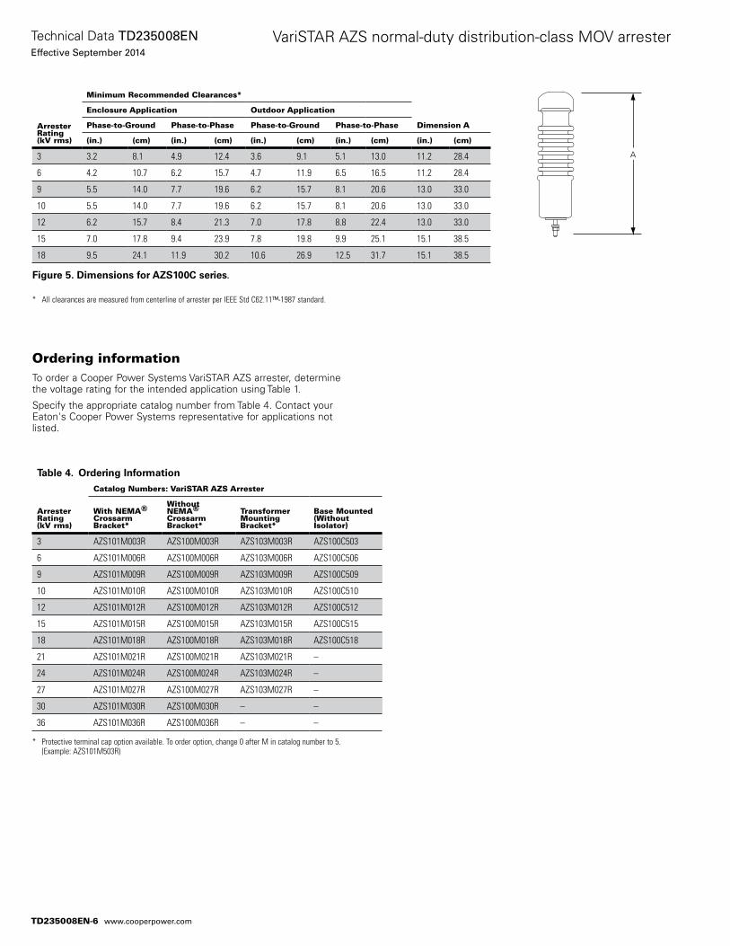
Figure 5. Dimensions for AZS100C series.
* All clearances are measured from centerline of arrester per IEEE Std C62.11™-1987 standard.
Ordering informationTo order a Cooper Power Systems VariSTAR AZS arrester, determine the voltage rating for the intended application using Table 1.
Specify the appropriate catalog number from Table 4. Contact your Eaton's Cooper Power Systems representative for applications not listed.
Table 4. Ordering Information
ArresterRating(kV rms)
Catalog Numbers: VariSTAR AZS Arrester
With NEMA®CrossarmBracket*
Without NEMA®CrossarmBracket*
Transformer MountingBracket*
Base Mounted(WithoutIsolator)
3 AZS101M003R AZS100M003R AZS103M003R AZS100C503
6 AZS101M006R AZS100M006R AZS103M006R AZS100C506
9 AZS101M009R AZS100M009R AZS103M009R AZS100C509
10 AZS101M010R AZS100M010R AZS103M010R AZS100C510
12 AZS101M012R AZS100M012R AZS103M012R AZS100C512
15 AZS101M015R AZS100M015R AZS103M015R AZS100C515
18 AZS101M018R AZS100M018R AZS103M018R AZS100C518
21 AZS101M021R AZS100M021R AZS103M021R –
24 AZS101M024R AZS100M024R AZS103M024R –
27 AZS101M027R AZS100M027R AZS103M027R –
30 AZS101M030R AZS100M030R – –
36 AZS101M036R AZS100M036R – –
* Protective terminal cap option available. To order option, change 0 after M in catalog number to 5. (Example: AZS101M503R)
ArresterRating(kV rms)
Minimum Recommended Clearances*
Dimension A
Enclosure Application Outdoor Application
Phase-to-Ground Phase-to-Phase Phase-to-Ground Phase-to-Phase
(in.) (cm) (in.) (cm) (in.) (cm) (in.) (cm) (in.) (cm)
3 3.2 8.1 4.9 12.4 3.6 9.1 5.1 13.0 11.2 28.4
6 4.2 10.7 6.2 15.7 4.7 11.9 6.5 16.5 11.2 28.4
9 5.5 14.0 7.7 19.6 6.2 15.7 8.1 20.6 13.0 33.0
10 5.5 14.0 7.7 19.6 6.2 15.7 8.1 20.6 13.0 33.0
12 6.2 15.7 8.4 21.3 7.0 17.8 8.8 22.4 13.0 33.0
15 7.0 17.8 9.4 23.9 7.8 19.8 9.9 25.1 15.1 38.5
18 9.5 24.1 11.9 30.2 10.6 26.9 12.5 31.7 15.1 38.5
A
TD235008EN-6
Technical Data TD235008ENEffective September 2014
VariSTAR AZS normal-duty distribution-class MOV arrester
www.cooperpower.com
This page is intentionally left blank.
TD235008EN-7
Technical Data TD235008ENEffective September 2014
VariSTAR AZS normal-duty distribution-class MOV arrester
www.cooperpower.com
Eaton, Cooper Power Systems, Isolator, and VariSTAR are valuable trademarks of Eaton in the U.S. and other countries. You are not permitted to use the these trademarks without the prior written consent of Eaton.IEEE Std C62.11™-1987 standard is a trademark of the Institute of Electrical and Electronics Engineers, Inc. (IEEE). This publication/product is not endorsed or approved by the IEEE.
VariSTAR AZS normal-duty distribution-class MOV arrester
Eaton1000 Eaton BoulevardCleveland, OH 44122United StatesEaton.com
Eaton’s Cooper Power Systems Business2300 Badger DriveWaukesha, WI 53188United StatesCooperpower.com
© 2014 EatonAll Rights ReservedPrinted in USAPublication No. TD235008EN
Technical Data TD235008ENEffective September 2014
For Eaton's Cooper Power Systems VariSTAR AZS MOV surge arrester product information call 1-877-277-4636 or visit: www.cooperpower.com.
TD235008EN-8
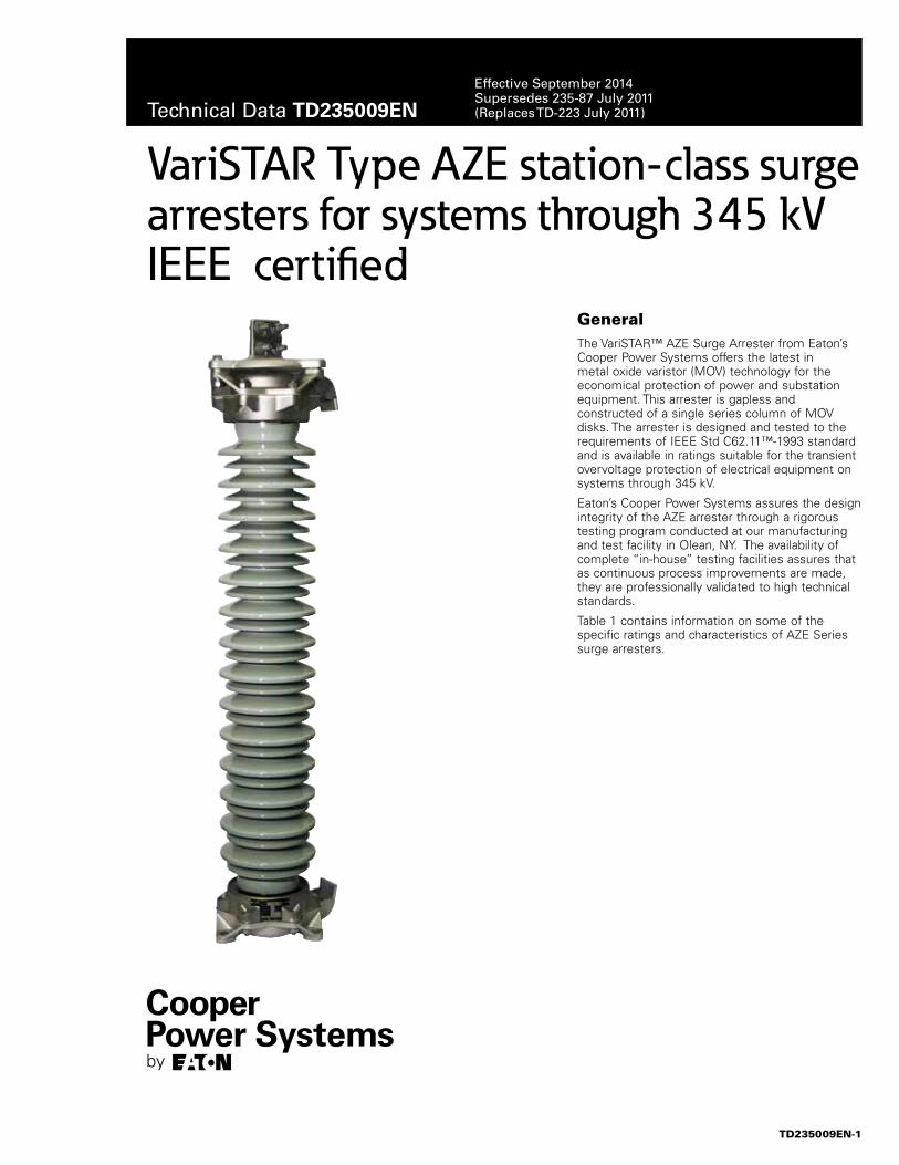
VariSTAR Type AZE station-class surge arresters for systems through 345 kV IEEE certified
GeneralThe VariSTAR™ AZE Surge Arrester from Eaton’s Cooper Power Systems offers the latest in metal oxide varistor (MOV) technology for the economical protection of power and substation equipment. This arrester is gapless and constructed of a single series column of MOV disks. The arrester is designed and tested to the requirements of IEEE Std C62.11™-1993 standard and is available in ratings suitable for the transient overvoltage protection of electrical equipment on systems through 345 kV.
Eaton’s Cooper Power Systems assures the design integrity of the AZE arrester through a rigorous testing program conducted at our manufacturing and test facility in Olean, NY. The availability of complete “in-house” testing facilities assures that as continuous process improvements are made, they are professionally validated to high technical standards.
Table 1 contains information on some of the specific ratings and characteristics of AZE Series surge arresters.
TD235009EN-1
Technical Data TD235009ENEffective September 2014Supersedes 235-87 July 2011 (Replaces TD-223 July 2011)
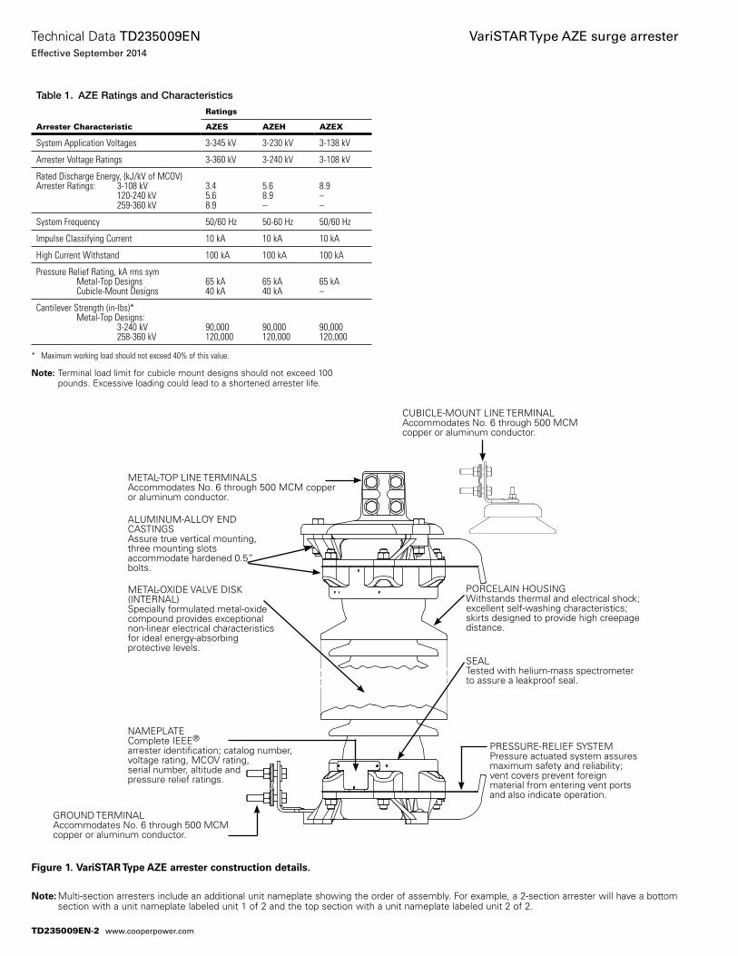
Figure 1. VariSTAR Type AZE arrester construction details.
otee:N Multi-section arresters include an additional unit nameplate showing the order of assembly. For example, a 2-section arrester will have a bottom section with a unit nameplate labeled unit 1 of 2 and the top section with a unit nameplate labeled unit 2 of 2.
METAL-TOP LINE TERMINALSAccommodates No. 6 through 500 MCM copper or aluminum conductor.
ALUMINUM-ALLOY END CASTINGSAssure true vertical mounting, three mounting slots accommodate hardened 0.5” bolts.
METAL-OXIDE VALVE DISK (INTERNAL)Specially formulated metal-oxide compound provides exceptional non-linear electrical characteristics for ideal energy-absorbing protective levels.
NAMEPLATEComplete IEEE® arrester identification; catalog number, voltage rating, MCOV rating, serial number, altitude and pressure relief ratings.
CUBICLE-MOUNT LINE TERMINALAccommodates No. 6 through 500 MCM copper or aluminum conductor.
PORCELAIN HOUSINGWithstands thermal and electrical shock; excellent self-washing characteristics; skirts designed to provide high creepage distance.
SEALTested with helium-mass spectrometer to assure a leakproof seal.
PRESSURE-RELIEF SYSTEMPressure actuated system assures maximum safety and reliability; vent covers prevent foreign material from entering vent ports and also indicate operation.
GROUND TERMINALAccommodates No. 6 through 500 MCM copper or aluminum conductor.
Table 1. AZE Ratings and Characteristics
Arrester Characteristic
Ratings
AZES AZEH AZEX
System Application Voltages 3-345 kV 3-230 kV 3-138 kV
Arrester Voltage Ratings 3-360 kV 3-240 kV 3-108 kV
Rated Discharge Energy, (kJ/kV of MCOV)Arrester Ratings: 3-108 kV 120-240 kV 259-360 kV
3.45.68.9
5.68.9–
8.9––
System Frequency 50/60 Hz 50-60 Hz 50/60 Hz
Impulse Classifying Current 10 kA 10 kA 10 kA
High Current Withstand 100 kA 100 kA 100 kA
Pressure Relief Rating, kA rms sym Metal-Top Designs Cubicle-Mount Designs
65 kA40 kA
65 kA40 kA
65 kA–
Cantilever Strength (in-lbs)* Metal-Top Designs: 3-240 kV 258-360 kV
90,000120,000
90,000120,000
90,000120,000
* Maximum working load should not exceed 40% of this value.
otee:N Terminal load limit for cubicle mount designs should not exceed 100 pounds. Excessive loading could lead to a shortened arrester life.
Technical Data TD235009ENEffective September 2014
VariSTAR Type AZE surge arrester
www.cooperpower.comTD235009EN-2
ConstructionExternal
The Type AZE station class arrester is available in two design configurations - a metal-top design in ratings 3-360 kV and a cubicle-mount design in ratings 3-48 kV. Cubicle-mount designs are ideally suited for confined spaces where clearances between live parts are limited.
The wet-process porcelain housing features an alternating shed design (ratings >48 kV) that provides excellent resistance to the effects of atmospheric housing contamination. AZE arresters are available with optional extra creepage porcelains for use in areas with extreme natural atmospheric and man-made pollution.
The dielectric properties of the porcelain are coordinated with the electrical protective characteristics of the arrester. The unit end castings are of a corrosion-resistant aluminum alloy configured for interchangeable mounting with other manufacturers’ arresters for ease in upgrading to the VariSTAR arrester technology. This three-footed mounting is provided on a 8.75 to 10 inch diameter pattern for customer supplied 0.5 inch diameter hardware.
High Cantilever strength assures mechanical integrity (Table 1 lists the cantilever strength of metal-top AZES arresters). Eaton’s Cooper Power Systems recommends that a load limit of 100 pounds not be exceeded on the line terminal of cubicle mount designs. Loads exceeding this limit could cause a shortening of arrester life. Housings are available in standard grey or optional brown glaze color.
Standard line and ground terminal connectors accommodate up to a 0.75 inch diameter conductor. Insulating bases and discharge counters are optionally available for in-service monitoring of arrester discharge activity.
The end fittings and porcelain housing of each arrester unit are sealed and tested by means of a sensitive helium mass spectrometer; this assures that the quality and insulation protection provided by the arrester is never compromised over its lifetime by the entrance of moisture. A corrosion-resistant nameplate is provided and contains all information required by Standards. In addition, stacking arrangement information is provided for multi-unit arresters. Voltage grading rings are included for arresters rated 172 kV and above.
Internal
VariSTAR AZE arresters are a totally gapless MOV design. Gapless construction makes a significant contribution to the performance of arresters through the elimination of gap reseal as a consideration associated with the discharge of switching surge currents. The specially formulated metal-oxide varistors, manufactured under Eaton’s Cooper Power Systems exclusive quality control, provide exceptional non-linear protective characteristics, durability, and dependable energy dissipation capabilities.
OperationThe VariSTAR AZE arrester conducts only a few milliamperes of leakage current when energized at normal system voltage. When a surge event occurs, the arrester conducts only the current, and consequently the energy, necessary to limit the overvoltage. It provides precise and predictable protection, minimizes the absorbed energy, and does not discharge power frequency systems currents.
A controlled and directed pressure relief system is incorporated in the VariSTAR AZE arrester design. In the unlikely event of an arrester failure, this pressure venting system rapidly relieves internal pressure and transfers the internal arc to the outside of the arrester porcelain through vent ports in the end castings.
When called upon to operate, this mechanism vents internal pressures in fractions of a cycle-preventing violent arrester failure. This mechanism is effective to system fault currents up to 65 kA in metal-top designs and 40 kA in cubicle-mount designs.
General application recommendationsThe rating of an arrester is the power-frequency line-to-ground voltage at which the arrester is designed to pass the IEEE Std C62.11™-1993 standard duty-cycle test. Table 2 provides a general guide for the selection of the proper arrester for a given system voltage. Eaton’s Cooper Power Systems application engineers are available to make specific system application recommendations.
3
Technical Data TD235009ENEffective September 2014
VariSTAR Type AZE surge arrester
www.cooperpower.com TD235009EN-3
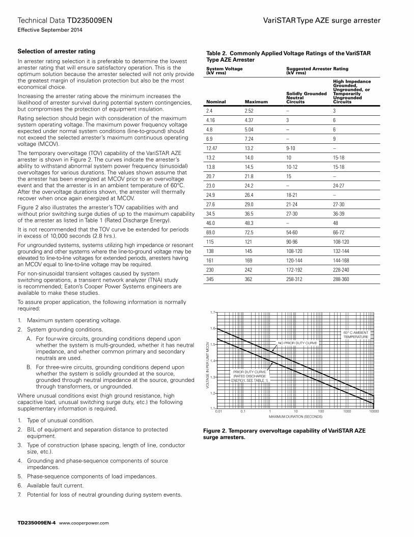
Selection of arrester rating
In arrester rating selection it is preferable to determine the lowest arrester rating that will ensure satisfactory operation. This is the optimum solution because the arrester selected will not only provide the greatest margin of insulation protection but also be the most economical choice.
Increasing the arrester rating above the minimum increases the likelihood of arrester survival during potential system contingencies, but compromises the protection of equipment insulation.
Rating selection should begin with consideration of the maximum system operating voltage. The maximum power frequency voltage expected under normal system conditions (line-to-ground) should not exceed the selected arrester’s maximum continuous operating voltage (MCOV).
The temporary overvoltage (TOV) capability of the VariSTAR AZE arrester is shown in Figure 2. The curves indicate the arrester’s ability to withstand abnormal system power frequency (sinusoidal) overvoltages for various durations. The values shown assume that the arrester has been energized at MCOV prior to an overvoltage event and that the arrester is in an ambient temperature of 60°C. After the overvoltage durations shown, the arrester will thermally recover when once again energized at MCOV.
Figure 2 also illustrates the arrester’s TOV capabilities with and without prior switching surge duties of up to the maximum capability of the arrester as listed in Table 1 (Rated Discharge Energy).
It is not recommended that the TOV curve be extended for periods in excess of 10,000 seconds (2.8 hrs.).
For ungrounded systems, systems utilizing high impedance or resonant grounding and other systems where the line-to-ground voltage may be elevated to line-to-line voltages for extended periods, arresters having an MCOV equal to line-to-line voltage may be required.
For non-sinusoidal transient voltages caused by system switching operations, a transient network analyzer (TNA) study is recommended; Eaton’s Cooper Power Systems engineers are available to make these studies.
To assure proper application, the following information is normally required:
1. Maximum system operating voltage.
2. System grounding conditions.
A. For four-wire circuits, grounding conditions depend upon whether the system is multi-grounded, whether it has neutral impedance, and whether common primary and secondary neutrals are used.
B. For three-wire circuits, grounding conditions depend upon whether the system is solidly grounded at the source, grounded through neutral impedance at the source, grounded through transformers, or ungrounded.
Where unusual conditions exist (high ground resistance, high capacitive load, unusual switching surge duty, etc.) the following supplementary information is required.
1. Type of unusual condition.
2. BIL of equipment and separation distance to protected equipment.
3. Type of construction (phase spacing, length of line, conductor size, etc.).
4. Grounding and phase-sequence components of source impedances.
5. Phase-sequence components of load impedances.
6. Available fault current.
7. Potential for loss of neutral grounding during system events.
Table 2. Commonly Applied Voltage Ratings of the VariSTAR Type AZE Arrester
System Voltage(kV rms)
Suggested Arrester Rating(kV rms)
Nominal Maximum
Solidly Grounded Neutral Circuits
High ImpedanceGrounded,Ungrounded, orTemporarilyUngrounded Circuits
2.4 2.52 – 3
4.16 4.37 3 6
4.8 5.04 – 6
6.9 7.24 – 9
12.47 13.2 9-10 –
13.2 14.0 10 15-18
13.8 14.5 10-12 15-18
20.7 21.8 15 –
23.0 24.2 – 24-27
24.9 26.4 18-21 –
27.6 29.0 21-24 27-30
34.5 36.5 27-30 36-39
46.0 48.3 – 48
69.0 72.5 54-60 66-72
115 121 90-96 108-120
138 145 108-120 132-144
161 169 120-144 144-168
230 242 172-192 228-240
345 362 258-312 288-360
1.1
1.2
1.3
1.4
1.5
1.6
1.7
0.01 0.1 1 10 100 1000 10000
MAXIMUM DURATION (SECONDS)
VO
LTA
GE
IN P
ER
UN
IT M
CO
V
PRIOR DUTY CURVE(RATED DISCHARGE
ENERGY, SEE TABLE 1)
NO PRIOR DUTY CURVE
60° C AMBIENTTEMPERATURE
Figure 2. Temporary overvoltage capability of VariSTAR AZE surge arresters.
TD235009EN-4
Technical Data TD235009ENEffective September 2014
VariSTAR Type AZE surge arrester
www.cooperpower.com
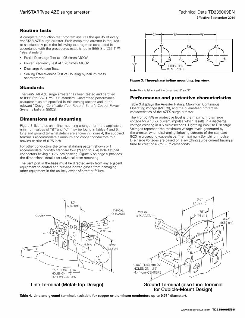
Routine testsA complete production test program assures the quality of every VariSTAR AZE surge arrester. Each completed arrester is required to satisfactorily pass the following test regimen conducted in accordance with the procedures established in IEEE Std C62.11™-1993 standard.• Partial Discharge Test at 1.05 times MCOV.• Power Frequency Test at 1.20 times MCOV.• Discharge Voltage Test.• Sealing Effectiveness Test of Housing by helium mass
spectrometer.
StandardsThe VariSTAR AZE surge arrester has been tested and certified to IEEE Std C62.11™-1993 standard. Guaranteed performance characteristics are specified in this catalog section and in the relevant “Design Certification Test Report” Eaton’s Cooper Power Systems bulletin 95028.
Dimensions and mountingFigure 3 illustrates an in-line mounting arrangement; the applicable minimum values of “B” and “C” may be found in Tables 4 and 5. Line and ground terminal details are shown in Figure 4; the supplied terminals accommodate aluminum and copper conductors to a maximum size of 0.75 inch.
For other conductors the terminal drilling pattern shown will accommodate industry standard two (2) and four (4) hole flat pad connectors having a 1.75 inch spacing. Figure 5 on page 9 provides the dimensional details for universal base mounting.
The vent port in the base must be directed away from any adjacent equipment to control and prevent ionized gases from damaging other equipment in the unlikely event of arrester failure.
Performance and protective characteristicsTable 3 displays the Arrester Rating, Maximum Continuous Operating Voltage (MCOV), and the guaranteed protective characteristics of the AZES surge arrester.
The Front-of-Wave protective level is the maximum discharge voltage for a 10 kA current impulse which results in a discharge voltage cresting in 0.5 microseconds. Lightning impulse Discharge Voltages represent the maximum voltage levels generated by the arrester when discharging lightning currents of the standard 8/20 microsecond wave-shape. The maximum Switching Impulse Discharge Voltages are based on a switching surge current having a time to crest of 45 to 60 microseconds.
Table 4. Line and ground terminals (suitable for copper or aluminum conductors up to 0.75” diameter).
DIRECTEDVENT PORT
"C"
"C" "B" "B"
Figure 3. Three-phase in-line mounting, top view.
Line Terminal (Metal-Top Design) Ground Terminal (also Line Terminal for Cubicle-Mount Design)
Notee: Refer to Tables 4 and 5 for Dimensions “B” and “C”.
TYPICAL4 PLACES
0.56” (1.43 cm) DIAHOLES ON 1.75”(4.44 cm) CENTERS
3.0”(7.62 cm)
1.75”(4.44 cm)
3.75”(9.52 cm)
TYPICAL4 PLACES
3.75”(9.52 cm)
3.0”(7.62 cm)
1.75”(4.44 cm)
CLAMP
0.75”(1.90 cm)
0.56” (1.43 cm) DIAHOLES ON 1.75”(4.44 cm) CENTERS
TD235009EN-5
Technical Data TD235009ENEffective September 2014
VariSTAR Type AZE surge arrester
www.cooperpower.com
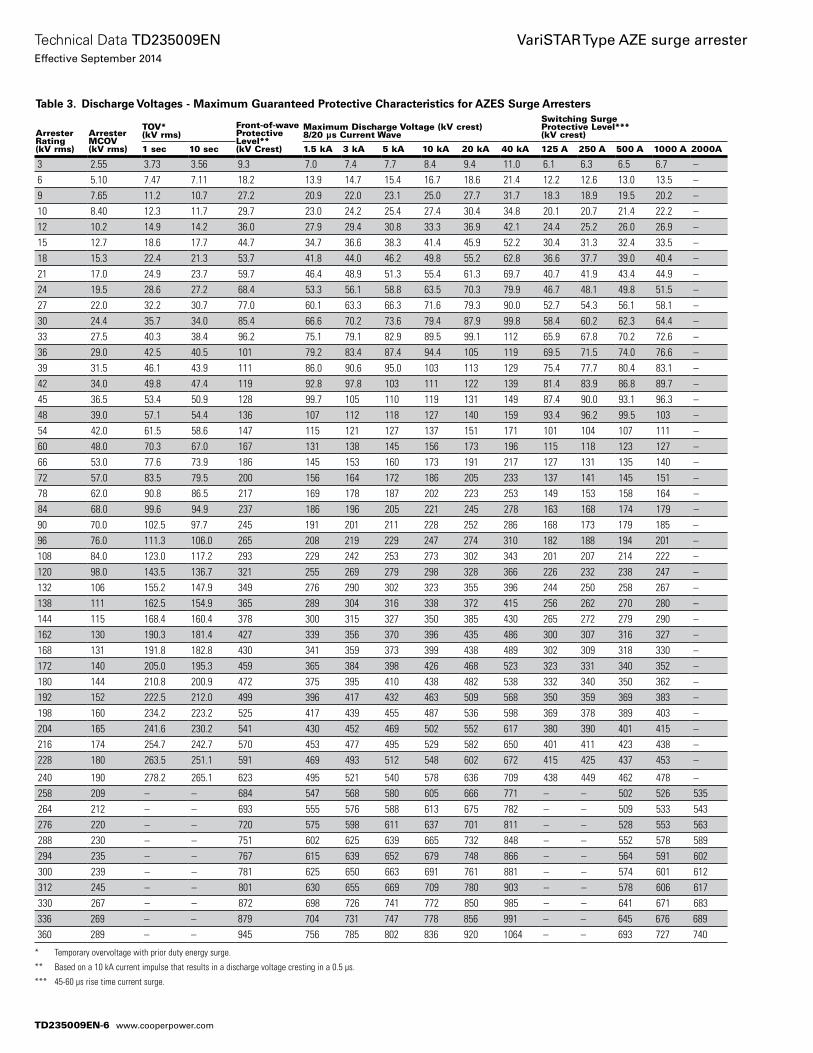
* Temporary overvoltage with prior duty energy surge.
** Based on a 10 kA current impulse that results in a discharge voltage cresting in a 0.5 µs.
*** 45-60 µs rise time current surge.
Table 3. Discharge Voltages - Maximum Guaranteed Protective Characteristics for AZES Surge Arresters
ArresterRating(kV rms)
ArresterMCOV(kV rms)
TOV*(kV rms)
Front-of-waveProtectiveLevel**(kV Crest)
Maximum Discharge Voltage (kV crest)8/20 µs Current Wave
Switching SurgeProtective Level***(kV crest)
1 sec 10 sec 1.5 kA 3 kA 5 kA 10 kA 20 kA 40 kA 125 A 250 A 500 A 1000 A 2000A
3 2.55 3.73 3.56 9.3 7.0 7.4 7.7 8.4 9.4 11.0 6.1 6.3 6.5 6.7 –6 5.10 7.47 7.11 18.2 13.9 14.7 15.4 16.7 18.6 21.4 12.2 12.6 13.0 13.5 –9 7.65 11.2 10.7 27.2 20.9 22.0 23.1 25.0 27.7 31.7 18.3 18.9 19.5 20.2 –10 8.40 12.3 11.7 29.7 23.0 24.2 25.4 27.4 30.4 34.8 20.1 20.7 21.4 22.2 –12 10.2 14.9 14.2 36.0 27.9 29.4 30.8 33.3 36.9 42.1 24.4 25.2 26.0 26.9 –15 12.7 18.6 17.7 44.7 34.7 36.6 38.3 41.4 45.9 52.2 30.4 31.3 32.4 33.5 –18 15.3 22.4 21.3 53.7 41.8 44.0 46.2 49.8 55.2 62.8 36.6 37.7 39.0 40.4 –21 17.0 24.9 23.7 59.7 46.4 48.9 51.3 55.4 61.3 69.7 40.7 41.9 43.4 44.9 –24 19.5 28.6 27.2 68.4 53.3 56.1 58.8 63.5 70.3 79.9 46.7 48.1 49.8 51.5 –27 22.0 32.2 30.7 77.0 60.1 63.3 66.3 71.6 79.3 90.0 52.7 54.3 56.1 58.1 –30 24.4 35.7 34.0 85.4 66.6 70.2 73.6 79.4 87.9 99.8 58.4 60.2 62.3 64.4 –33 27.5 40.3 38.4 96.2 75.1 79.1 82.9 89.5 99.1 112 65.9 67.8 70.2 72.6 –36 29.0 42.5 40.5 101 79.2 83.4 87.4 94.4 105 119 69.5 71.5 74.0 76.6 –39 31.5 46.1 43.9 111 86.0 90.6 95.0 103 113 129 75.4 77.7 80.4 83.1 –42 34.0 49.8 47.4 119 92.8 97.8 103 111 122 139 81.4 83.9 86.8 89.7 –45 36.5 53.4 50.9 128 99.7 105 110 119 131 149 87.4 90.0 93.1 96.3 –48 39.0 57.1 54.4 136 107 112 118 127 140 159 93.4 96.2 99.5 103 –54 42.0 61.5 58.6 147 115 121 127 137 151 171 101 104 107 111 –60 48.0 70.3 67.0 167 131 138 145 156 173 196 115 118 123 127 –66 53.0 77.6 73.9 186 145 153 160 173 191 217 127 131 135 140 –72 57.0 83.5 79.5 200 156 164 172 186 205 233 137 141 145 151 –78 62.0 90.8 86.5 217 169 178 187 202 223 253 149 153 158 164 –84 68.0 99.6 94.9 237 186 196 205 221 245 278 163 168 174 179 –90 70.0 102.5 97.7 245 191 201 211 228 252 286 168 173 179 185 –96 76.0 111.3 106.0 265 208 219 229 247 274 310 182 188 194 201 –108 84.0 123.0 117.2 293 229 242 253 273 302 343 201 207 214 222 –120 98.0 143.5 136.7 321 255 269 279 298 328 366 226 232 238 247 –132 106 155.2 147.9 349 276 290 302 323 355 396 244 250 258 267 –138 111 162.5 154.9 365 289 304 316 338 372 415 256 262 270 280 –144 115 168.4 160.4 378 300 315 327 350 385 430 265 272 279 290 –162 130 190.3 181.4 427 339 356 370 396 435 486 300 307 316 327 –168 131 191.8 182.8 430 341 359 373 399 438 489 302 309 318 330 –172 140 205.0 195.3 459 365 384 398 426 468 523 323 331 340 352 –180 144 210.8 200.9 472 375 395 410 438 482 538 332 340 350 362 –192 152 222.5 212.0 499 396 417 432 463 509 568 350 359 369 383 –198 160 234.2 223.2 525 417 439 455 487 536 598 369 378 389 403 –204 165 241.6 230.2 541 430 452 469 502 552 617 380 390 401 415 –216 174 254.7 242.7 570 453 477 495 529 582 650 401 411 423 438 –228 180 263.5 251.1 591 469 493 512 548 602 672 415 425 437 453 –
240 190 278.2 265.1 623 495 521 540 578 636 709 438 449 462 478 –258 209 – – 684 547 568 580 605 666 771 – – 502 526 535264 212 – – 693 555 576 588 613 675 782 – – 509 533 543276 220 – – 720 575 598 611 637 701 811 – – 528 553 563288 230 – – 751 602 625 639 665 732 848 – – 552 578 589294 235 – – 767 615 639 652 679 748 866 – – 564 591 602300 239 – – 781 625 650 663 691 761 881 – – 574 601 612312 245 – – 801 630 655 669 709 780 903 – – 578 606 617330 267 – – 872 698 726 741 772 850 985 – – 641 671 683336 269 – – 879 704 731 747 778 856 991 – – 645 676 689360 289 – – 945 756 785 802 836 920 1064 – – 693 727 740
TD235009EN-6
Technical Data TD235009ENEffective September 2014
VariSTAR Type AZE surge arrester
www.cooperpower.com
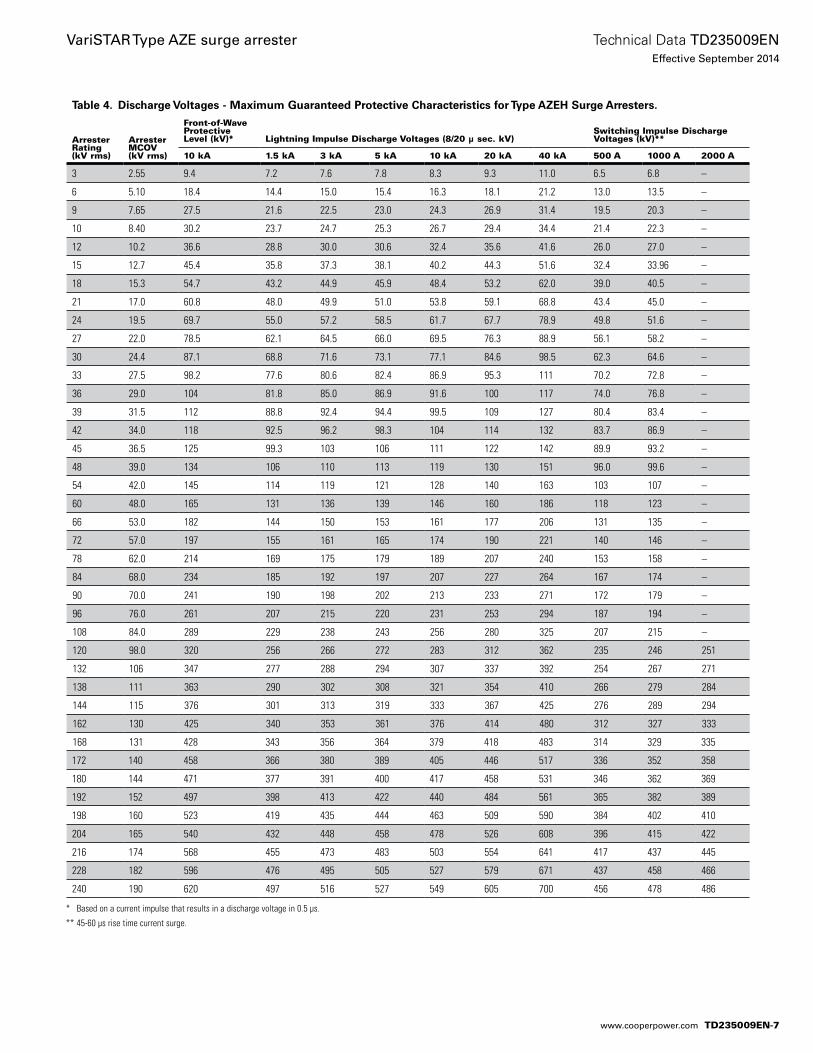
Table 4. Discharge Voltages - Maximum Guaranteed Protective Characteristics for Type AZEH Surge Arresters.
Arrester Rating(kV rms)
Arrester MCOV (kV rms)
Front-of-Wave Protective Level (kV)* Lightning Impulse Discharge Voltages (8/20 μ sec. kV)
Switching Impulse Discharge Voltages (kV)**
10 kA 1.5 kA 3 kA 5 kA 10 kA 20 kA 40 kA 500 A 1000 A 2000 A
3 2.55 9.4 7.2 7.6 7.8 8.3 9.3 11.0 6.5 6.8 –
6 5.10 18.4 14.4 15.0 15.4 16.3 18.1 21.2 13.0 13.5 –
9 7.65 27.5 21.6 22.5 23.0 24.3 26.9 31.4 19.5 20.3 –
10 8.40 30.2 23.7 24.7 25.3 26.7 29.4 34.4 21.4 22.3 –
12 10.2 36.6 28.8 30.0 30.6 32.4 35.6 41.6 26.0 27.0 –
15 12.7 45.4 35.8 37.3 38.1 40.2 44.3 51.6 32.4 33.96 –
18 15.3 54.7 43.2 44.9 45.9 48.4 53.2 62.0 39.0 40.5 –
21 17.0 60.8 48.0 49.9 51.0 53.8 59.1 68.8 43.4 45.0 –
24 19.5 69.7 55.0 57.2 58.5 61.7 67.7 78.9 49.8 51.6 –
27 22.0 78.5 62.1 64.5 66.0 69.5 76.3 88.9 56.1 58.2 –
30 24.4 87.1 68.8 71.6 73.1 77.1 84.6 98.5 62.3 64.6 –
33 27.5 98.2 77.6 80.6 82.4 86.9 95.3 111 70.2 72.8 –
36 29.0 104 81.8 85.0 86.9 91.6 100 117 74.0 76.8 –
39 31.5 112 88.8 92.4 94.4 99.5 109 127 80.4 83.4 –
42 34.0 118 92.5 96.2 98.3 104 114 132 83.7 86.9 –
45 36.5 125 99.3 103 106 111 122 142 89.9 93.2 –
48 39.0 134 106 110 113 119 130 151 96.0 99.6 –
54 42.0 145 114 119 121 128 140 163 103 107 –
60 48.0 165 131 136 139 146 160 186 118 123 –
66 53.0 182 144 150 153 161 177 206 131 135 –
72 57.0 197 155 161 165 174 190 221 140 146 –
78 62.0 214 169 175 179 189 207 240 153 158 –
84 68.0 234 185 192 197 207 227 264 167 174 –
90 70.0 241 190 198 202 213 233 271 172 179 –
96 76.0 261 207 215 220 231 253 294 187 194 –
108 84.0 289 229 238 243 256 280 325 207 215 –
120 98.0 320 256 266 272 283 312 362 235 246 251
132 106 347 277 288 294 307 337 392 254 267 271
138 111 363 290 302 308 321 354 410 266 279 284
144 115 376 301 313 319 333 367 425 276 289 294
162 130 425 340 353 361 376 414 480 312 327 333
168 131 428 343 356 364 379 418 483 314 329 335
172 140 458 366 380 389 405 446 517 336 352 358
180 144 471 377 391 400 417 458 531 346 362 369
192 152 497 398 413 422 440 484 561 365 382 389
198 160 523 419 435 444 463 509 590 384 402 410
204 165 540 432 448 458 478 526 608 396 415 422
216 174 568 455 473 483 503 554 641 417 437 445
228 182 596 476 495 505 527 579 671 437 458 466
240 190 620 497 516 527 549 605 700 456 478 486
* Based on a current impulse that results in a discharge voltage in 0.5 μs.
** 45-60 μs rise time current surge.
TD235009EN-7
Technical Data TD235009ENEffective September 2014
VariSTAR Type AZE surge arrester
www.cooperpower.com
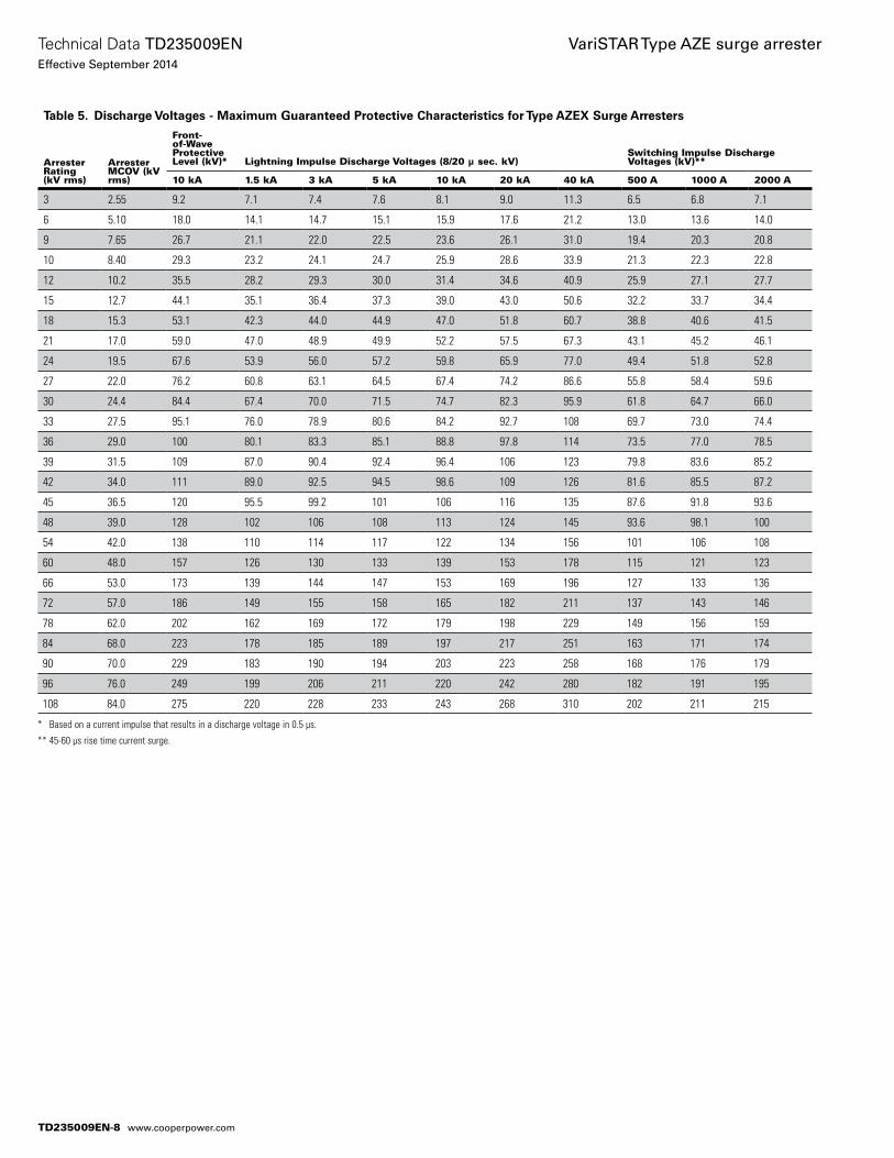
Table 5. Discharge Voltages - Maximum Guaranteed Protective Characteristics for Type AZEX Surge Arresters
Arrester Rating(kV rms)
Arrester MCOV (kV rms)
Front-of-Wave Protective Level (kV)* Lightning Impulse Discharge Voltages (8/20 μ sec. kV)
Switching Impulse Discharge Voltages (kV)**
10 kA 1.5 kA 3 kA 5 kA 10 kA 20 kA 40 kA 500 A 1000 A 2000 A
3 2.55 9.2 7.1 7.4 7.6 8.1 9.0 11.3 6.5 6.8 7.1
6 5.10 18.0 14.1 14.7 15.1 15.9 17.6 21.2 13.0 13.6 14.0
9 7.65 26.7 21.1 22.0 22.5 23.6 26.1 31.0 19.4 20.3 20.8
10 8.40 29.3 23.2 24.1 24.7 25.9 28.6 33.9 21.3 22.3 22.8
12 10.2 35.5 28.2 29.3 30.0 31.4 34.6 40.9 25.9 27.1 27.7
15 12.7 44.1 35.1 36.4 37.3 39.0 43.0 50.6 32.2 33.7 34.4
18 15.3 53.1 42.3 44.0 44.9 47.0 51.8 60.7 38.8 40.6 41.5
21 17.0 59.0 47.0 48.9 49.9 52.2 57.5 67.3 43.1 45.2 46.1
24 19.5 67.6 53.9 56.0 57.2 59.8 65.9 77.0 49.4 51.8 52.8
27 22.0 76.2 60.8 63.1 64.5 67.4 74.2 86.6 55.8 58.4 59.6
30 24.4 84.4 67.4 70.0 71.5 74.7 82.3 95.9 61.8 64.7 66.0
33 27.5 95.1 76.0 78.9 80.6 84.2 92.7 108 69.7 73.0 74.4
36 29.0 100 80.1 83.3 85.1 88.8 97.8 114 73.5 77.0 78.5
39 31.5 109 87.0 90.4 92.4 96.4 106 123 79.8 83.6 85.2
42 34.0 111 89.0 92.5 94.5 98.6 109 126 81.6 85.5 87.2
45 36.5 120 95.5 99.2 101 106 116 135 87.6 91.8 93.6
48 39.0 128 102 106 108 113 124 145 93.6 98.1 100
54 42.0 138 110 114 117 122 134 156 101 106 108
60 48.0 157 126 130 133 139 153 178 115 121 123
66 53.0 173 139 144 147 153 169 196 127 133 136
72 57.0 186 149 155 158 165 182 211 137 143 146
78 62.0 202 162 169 172 179 198 229 149 156 159
84 68.0 223 178 185 189 197 217 251 163 171 174
90 70.0 229 183 190 194 203 223 258 168 176 179
96 76.0 249 199 206 211 220 242 280 182 191 195
108 84.0 275 220 228 233 243 268 310 202 211 215
* Based on a current impulse that results in a discharge voltage in 0.5 μs.
** 45-60 μs rise time current surge.
TD235009EN-8
Technical Data TD235009ENEffective September 2014
VariSTAR Type AZE surge arrester
www.cooperpower.com
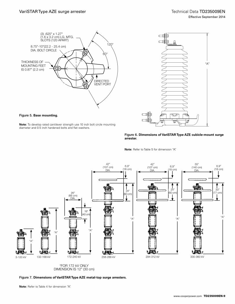
60°
(3) .625" x 1.27" (1.6 x 3.2 cm) LG. MTG.SLOTS (120 APART)
8.75"-10"(22.2 - 25.4 cm) DIA. BOLT CIRCLE
120°
THICKNESS OFMOUNTING FEETIS 0.87" (2.2 cm)
DIRECTED VENT PORT
Figure 5. Base mounting.
otee:N To develop rated cantilever strength use 10 inch bolt circle mounting diameter and 0.5 inch hardened bolts and flat washers.
Figure 7. Dimensions of VariSTAR Type AZE metal-top surge arresters.
otee:N Refer to Table 4 for dimension “A”.
Figure 6. Dimensions of VariSTAR Type AZE cubicle-mount surge arrester.
otee:N Refer to Table 5 for dimension “A”.
“A”
3-120 kV 132-168 kV 172-240 kV 258-288 kV 294-312 kV 330-360 kV
26”(66 cm)
DIA.
42”(107 cm)
DIA.
55”(140 cm)
DIA.
42”(107 cm)
DIA.
6.9”(18 cm)
6.9”(18 cm)
6.9”(18 cm)
*FOR 172 kV ONLYDIMENSION IS 12” (30 cm)
“A”
“A”
“A”
24”(60 cm)
30”(77 cm)
24”(60 cm)
“A”“A”
16”(40 cm)
“A”
TD235009EN-9
Technical Data TD235009ENEffective September 2014
VariSTAR Type AZE surge arrester
www.cooperpower.com
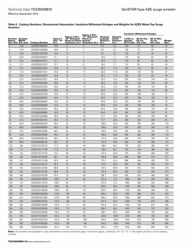
Table 6. Catalog Numbers, Dimensional Information, Insulation Withstand Voltages and Weights for AZES Metal-Top Surge Arresters
Arrester Rating (kV, rms)
Arrester MCOV(kV, rms) Catalog Number
Figure 7 Dim. “A”(in.)
Figure 3 Dim. “B” Minimum Phase-to-Phase Clearance (in.)
Figure 3 Dim. “C” Minimum Phase-to-Ground Clearance (in.)
HousingLeakage Distance (in.)
Housing Strike Distance (in.)
Insulation Withstand Voltages
Weight(lbs.)
1.2/50 µs Impulse (kV Crest)
60 Hz Dry, 60 sec (kV, rms)
60 Hz Wet, 10 sec (kV, rms)
3 2.55 AZES001G002003 18.6 12 6 9.2 5.2 130 75 40 426 5.10 AZES001G005006 18.6 12 7 9.2 5.2 130 75 40 429 7.65 AZES001G007009 18.6 13 7 9.2 5.2 130 75 40 4310 8.40 AZES002G008010 21.1 13 7 16.0 7.7 170 95 65 4812 10.2 AZES002G010012 21.1 14 8 16.0 7.7 170 95 65 4915 12.7 AZES002G012015 21.1 14 9 16.0 7.7 170 95 65 4918 15.3 AZES003G015018 24.8 15 10 26.2 11.4 230 125 95 5621 17.0 AZES003G017021 24.8 16 11 26.2 11.4 230 125 95 5724 19.5 AZES003G019024 24.8 16 11 26.2 11.4 230 125 95 5827 22.0 AZES004G022027 28.6 17 12 36.3 15.2 265 150 125 6530 24.4 AZES004G024030 28.6 18 13 36.3 15.2 265 150 125 6533 27.5 AZES004G027033 28.6 20 14 36.3 15.2 265 150 125 6636 29.0 AZES004G029036 28.6 20 14 36.3 15.2 265 150 125 6639 31.5 AZES005G031039 33.6 21 15 49.9 20.2 320 190 165 7742 34.0 AZES005G034042 33.6 22 16 49.9 20.2 320 190 165 7845 36.5 AZES005G036045 33.6 23 17 49.9 20.2 320 190 165 7848 39.0 AZES005G039048 33.6 24 18 49.9 20.2 320 190 165 7854 42.0 AZES006G042054 36.6 25 20 64.8 23.6 365 200 170 8660 48.0 AZES006G048060 36.6 28 22 64.8 23.6 365 200 170 8766 53.0 AZES007G053066 39.4 30 24 73.7 26.5 385 235 200 9672 57.0 AZES007G057072 39.4 31 26 73.7 26.5 385 235 200 9778 62.0 AZES008G062078 48.0 33 28 100.0 35.0 505 305 260 11684 68.0 AZES008G068084 48.0 36 30 100.0 35.0 505 305 260 11890 70.0 AZES008G070090 48.0 36 31 100.0 35.0 505 305 260 11896 76.0 AZES008G076096 48.0 39 33 100.0 35.0 505 305 260 119108 84.0 AZES009G084108 56.5 42 36 127.0 43.6 650 370 300 161120 98.0 AZES009G098120 56.5 43 37 127.0 43.6 650 370 300 175132 106 AZES012G106132 71.5 46 40 138.5 50.1 735 425 360 191138 111 AZES012G111138 71.5 47 42 138.5 50.1 735 425 360 193144 115 AZES013G115144 74.4 49 43 147.4 52.9 770 475 400 202162 130 AZES014G130162 80.1 54 48 164.8 58.6 865 490 415 217168 131 AZES015G131168 82.9 54 48 173.7 61.5 880 545 455 225172 140 AZES021G140172 83.2 72 59 173.7 59.4 920 535 450 237180 144 AZES022G144180 88.9 73 60 191.8 60.9 920 515 440 270192 152 AZES022G152192 88.9 76 63 191.8 60.9 920 515 440 273198 160 AZES023G160198 91.8 79 66 200.7 63.8 930 535 480 283204 165 AZES024G165204 100.3 81 68 227.0 72.3 1065 595 545 303216 174 AZES024G174216 100.3 84 71 227.0 72.3 1065 595 545 306228 182 AZES025G182228 108.9 86 73 254.0 80.9 1185 655 580 348240 190 AZES025G190240 108.9 89 76 254.0 80.9 1185 655 580 351258 209 AZES067G209258 123.9 105 84 265.5 83.9 1265 690 625 472264 212 AZES067G212264 123.9 106 85 265.5 83.9 1265 690 625 473276 220 AZES069G220276 132.5 108 87 291.8 92.4 1300 750 675 499288 230 AZES069G230288 132.5 111 90 291.8 92.4 1300 750 675 503294 235 AZES070G235294 135.3 113 92 300.7 95.3 1405 765 725 524300 239 AZES070G239300 135.3 114 93 300.7 95.3 1405 765 725 526312 245 AZES071G245312 141.0 116 95 318.8 100.9 1475 805 730 558330 267 AZES074G267330 152.4 136 108 354.0 109.5 1440 810 790 605336 269 AZES074G269336 152.4 136 109 354.0 109.5 1440 810 790 606360 289 AZES075G289360 161.0 143 115 381.0 118.0 1535 860 840 655
otee:N All arresters are available in grey (standard) or brown porcelain glaze. For brown glaze, substitute “B” for “G” in the eighth position of the catalog number.
TD235009EN-10
Technical Data TD235009ENEffective September 2014
VariSTAR Type AZE surge arrester
www.cooperpower.com
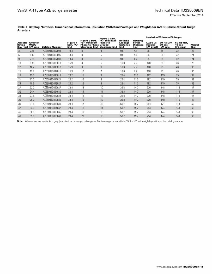
Table 7. Catalog Numbers, Dimensional Information, Insulation Withstand Voltages and Weights for AZES Cubicle-Mount Surge Arresters
Arrester Rating (kV, rms)
Arrester MCOV(kV, rms) Catalog Number
Figure 7 Dim. “A”(in.)
Figure 3 Dim. “B” Minimum Phase-to-Phase Clearance (in.)
Figure 3 Dim. “C” Minimum Phase-to-Ground Clearance (in.)
HousingLeakage Distance (in.)
Housing Strike Distance (in.)
Insulation Withstand Voltages
Weight(lbs.)
1.2/50 µs Impulse (kV Crest)
60 Hz Dry, 60 sec (kV, rms)
60 Hz Wet, 10 sec (kV, rms)
3 2.55 AZES091G002003 13.4 8 4 9.0 4.7 95 65 32 236 5.10 AZES091G005006 13.4 8 5 9.0 4.7 95 65 32 249 7.65 AZES091G007009 13.4 8 5 9.0 4.7 95 65 32 2410 8.40 AZES092G008010 15.9 8 5 16.0 7.2 128 93 46 2912 10.2 AZES092G010012 15.9 9 6 16.0 7.2 128 93 46 3015 12.7 AZES092G012015 15.9 10 7 16.0 7.2 128 93 46 3018 15.3 AZES093G015018 20.2 11 8 26.4 11.0 182 119 75 3821 17.0 AZES093G017021 20.2 12 8 26.4 11.0 182 119 75 3824 19.5 AZES093G019024 20.2 12 9 26.4 11.0 182 119 75 3927 22.0 AZES094G022027 23.4 13 10 36.8 14.7 230 148 115 4730 24.4 AZES094G024030 23.4 14 11 36.8 14.7 230 148 115 4733 27.5 AZES094G027033 23.4 15 12 36.8 14.7 230 148 115 4736 29.0 AZES094G029036 23.4 16 12 36.8 14.7 230 148 115 4839 31.5 AZES095G031039 28.4 17 13 50.7 19.7 294 174 143 5942 34.0 AZES095G034042 28.4 18 14 50.7 19.7 294 174 143 6045 36.5 AZES095G036045 28.4 19 15 50.7 19.7 294 174 143 6048 39.0 AZES095G039048 28.4 20 16 50.7 19.7 294 174 143 60
Note: All arresters are available in grey (standard) or brown porcelain glaze. For brown glaze, substitute “B” for “G” in the eighth position of the catalog number.
TD235009EN-11
Technical Data TD235009ENEffective September 2014
VariSTAR Type AZE surge arrester
www.cooperpower.com
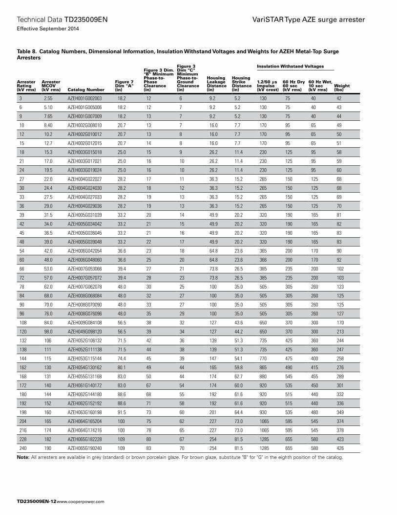
Table 8. Catalog Numbers, Dimensional Information, Insulation Withstand Voltages and Weights for AZEH Metal-Top Surge Arresters
Arrester Rating (kV rms)
Arrester MCOV (kV rms) Catalog Number
Figure 7 Dim "A" (in)
Figure 3 Dim. "B" Minimum Phase-to-Phase Clearance (in)
Figure 3 Dim "C" Minimum Phase-to-Ground Clearance (in)
Housing Leakage Distance (in)
Housing Strike Distance (in)
Insulation Withstand Voltages
Weight (lbs)
1.2/50 μs Impulse (kV crest)
60 Hz Dry 60 sec (kV rms)
60 Hz Wet, 10 sec (kV rms)
3 2.55 AZEH001G002003 18.2 12 6 9.2 5.2 130 75 40 42
6 5.10 AZEH001G005006 18.2 12 7 9.2 5.2 130 75 40 43
9 7.65 AZEH001G007009 18.2 13 7 9.2 5.2 130 75 40 44
10 8.40 AZEH002G008010 20.7 13 7 16.0 7.7 170 95 65 49
12 10.2 AZEH002G010012 20.7 13 8 16.0 7.7 170 95 65 50
15 12.7 AZEH002G012015 20.7 14 8 16.0 7.7 170 95 65 51
18 15.3 AZEH003G015018 25.0 15 9 26.2 11.4 230 125 95 58
21 17.0 AZEH003G017021 25.0 16 10 26.2 11.4 230 125 95 59
24 19.5 AZEH003G019024 25.0 16 10 26.2 11.4 230 125 95 60
27 22.0 AZEH004G022027 28.2 17 11 36.3 15.2 265 150 125 68
30 24.4 AZEH004G024030 28.2 18 12 36.3 15.2 265 150 125 68
33 27.5 AZEH004G027033 28.2 19 13 36.3 15.2 265 150 125 69
36 29.0 AZEH004G029036 28.2 19 13 36.3 15.2 265 150 125 70
39 31.5 AZEH005G031039 33.2 20 14 49.9 20.2 320 190 165 81
42 34.0 AZEH005G034042 33.2 21 15 49.9 20.2 320 190 165 82
45 36.5 AZEH005G036045 33.2 21 16 49.9 20.2 320 190 165 83
48 39.0 AZEH005G039048 33.2 22 17 49.9 20.2 320 190 165 83
54 42.0 AZEH006G042054 36.6 23 18 64.8 23.6 365 200 170 90
60 48.0 AZEH006G048060 36.6 25 20 64.8 23.6 366 200 170 92
66 53.0 AZEH007G053066 39.4 27 21 73.8 26.5 385 235 200 102
72 57.0 AZEH007G057072 39.4 28 23 73.8 26.5 385 235 200 103
78 62.0 AZEH007G062078 48.0 30 25 100 35.0 505 305 260 123
84 68.0 AZEH008G068084 48.0 32 27 100 35.0 505 305 260 125
90 70.0 AZEH008G070090 48.0 33 27 100 35.0 505 305 260 125
96 76.0 AZEH008G076096 48.0 35 29 100 35.0 505 305 260 127
108 84.0 AZEH009G084108 56.5 38 32 127 43.6 650 370 300 170
120 98.0 AZEH049G098120 56.5 39 34 127 44.2 650 370 300 213
132 106 AZEH052G106132 71.5 42 36 139 51.3 735 425 360 244
138 111 AZEH052G111138 71.5 44 38 139 51.3 735 425 360 247
144 115 AZEH053G115144 74.4 45 39 147 54.1 770 475 400 258
162 130 AZEH054G130162 80.1 49 44 165 59.8 865 490 415 276
168 131 AZEH055G131168 83.0 50 44 174 62.7 880 545 455 289
172 140 AZEH061G140172 83.0 67 54 174 60.0 920 535 450 301
180 144 AZEH062G144180 88.6 68 55 192 61.6 920 515 440 332
192 152 AZEH062G152192 88.6 71 58 192 61.6 920 515 440 336
198 160 AZEH063G160198 91.5 73 60 201 64.4 930 535 480 349
204 165 AZEH064G165204 100 75 62 227 73.0 1065 595 545 374
216 174 AZEH064G174216 100 78 65 227 73.0 1065 595 545 378
228 182 AZEH065G182228 109 80 67 254 81.5 1285 655 580 423
240 190 AZEH065G190240 109 83 70 254 81.5 1285 655 580 426
otee:N All arresters are available in grey (standard) or brown porcelain glaze. For brown glaze, substitute "B" for "G" in the eighth position of the catalog.
TD235009EN-12
Technical Data TD235009ENEffective September 2014
VariSTAR Type AZE surge arrester
www.cooperpower.com
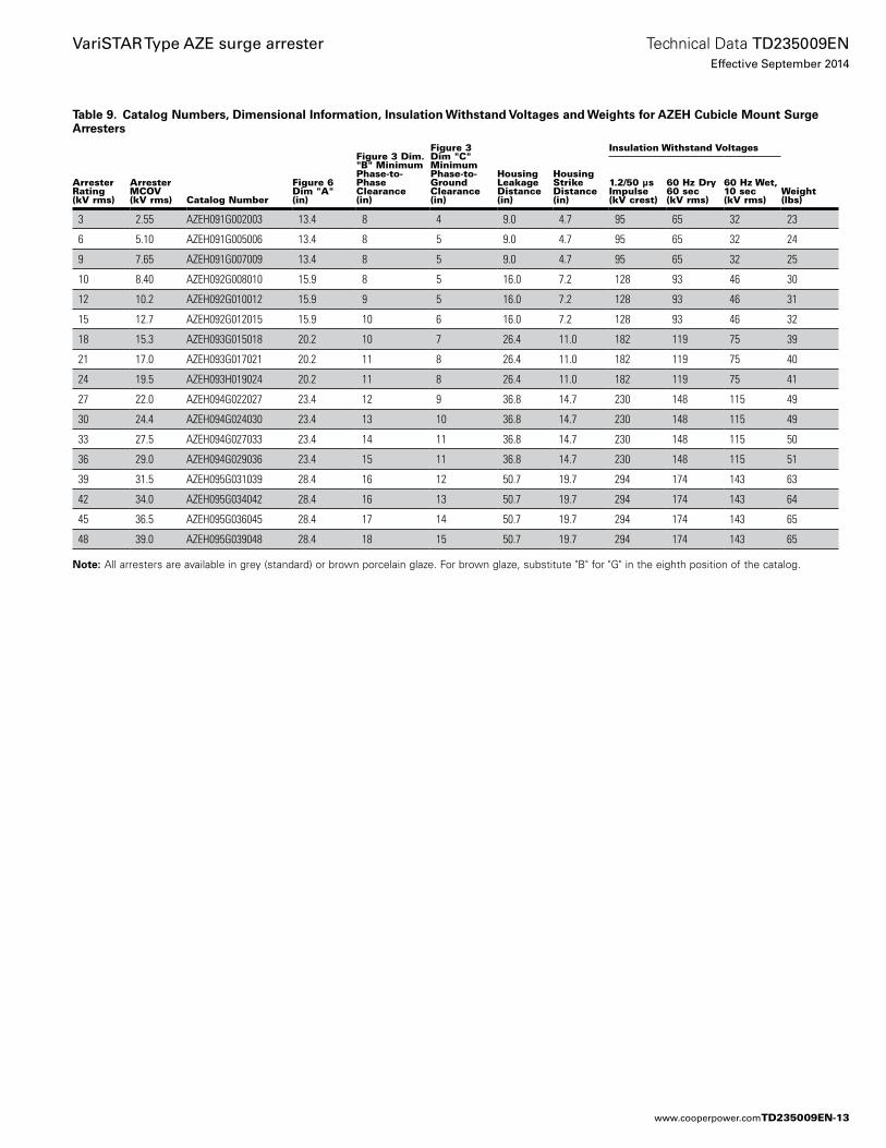
Table 9. Catalog Numbers, Dimensional Information, Insulation Withstand Voltages and Weights for AZEH Cubicle Mount Surge Arresters
Arrester Rating (kV rms)
Arrester MCOV (kV rms) Catalog Number
Figure 6 Dim "A" (in)
Figure 3 Dim. "B" Minimum Phase-to-Phase Clearance (in)
Figure 3 Dim "C" Minimum Phase-to-Ground Clearance (in)
Housing Leakage Distance (in)
Housing Strike Distance (in)
Insulation Withstand Voltages
Weight (lbs)
1.2/50 μs Impulse (kV crest)
60 Hz Dry 60 sec (kV rms)
60 Hz Wet, 10 sec (kV rms)
3 2.55 AZEH091G002003 13.4 8 4 9.0 4.7 95 65 32 23
6 5.10 AZEH091G005006 13.4 8 5 9.0 4.7 95 65 32 24
9 7.65 AZEH091G007009 13.4 8 5 9.0 4.7 95 65 32 25
10 8.40 AZEH092G008010 15.9 8 5 16.0 7.2 128 93 46 30
12 10.2 AZEH092G010012 15.9 9 5 16.0 7.2 128 93 46 31
15 12.7 AZEH092G012015 15.9 10 6 16.0 7.2 128 93 46 32
18 15.3 AZEH093G015018 20.2 10 7 26.4 11.0 182 119 75 39
21 17.0 AZEH093G017021 20.2 11 8 26.4 11.0 182 119 75 40
24 19.5 AZEH093H019024 20.2 11 8 26.4 11.0 182 119 75 41
27 22.0 AZEH094G022027 23.4 12 9 36.8 14.7 230 148 115 49
30 24.4 AZEH094G024030 23.4 13 10 36.8 14.7 230 148 115 49
33 27.5 AZEH094G027033 23.4 14 11 36.8 14.7 230 148 115 50
36 29.0 AZEH094G029036 23.4 15 11 36.8 14.7 230 148 115 51
39 31.5 AZEH095G031039 28.4 16 12 50.7 19.7 294 174 143 63
42 34.0 AZEH095G034042 28.4 16 13 50.7 19.7 294 174 143 64
45 36.5 AZEH095G036045 28.4 17 14 50.7 19.7 294 174 143 65
48 39.0 AZEH095G039048 28.4 18 15 50.7 19.7 294 174 143 65
otee:N All arresters are available in grey (standard) or brown porcelain glaze. For brown glaze, substitute "B" for "G" in the eighth position of the catalog.
TD235009EN-13
Technical Data TD235009ENEffective September 2014
VariSTAR Type AZE surge arrester
www.cooperpower.com
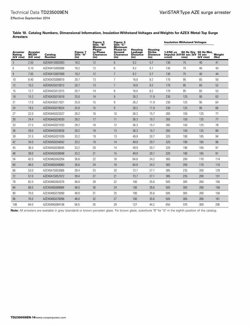
Table 10. Catalog Numbers, Dimensional Information, Insulation Withstand Voltages and Weights for AZEX Metal-Top Surge Arresters
Arrester Rating (kV rms)
Arrester MCOV (kV rms)
Catalog Number
Figure 7 Dim "A" (in)
Figure 3 Dim. "B" Minimum Phase-to-Phase Clearance (in)
Figure 3 Dim "C" Minimum Phase-to-Ground Clearance (in)
Housing Leakage Distance (in)
Housing Strike Distance (in)
Insulation Withstand Voltages
Weight (lbs)
1.2/50 μs Impulse (kV crest)
60 Hz Dry 60 sec (kV rms)
60 Hz Wet, 10 sec (kV rms)
3 2.55 AZEX041G002003 18.2 12 6 9.2 5.7 130 75 40 41
6 5.10 AZEX041G005006 18.2 12 6 9.2 5.7 130 75 40 43
9 7.65 AZEX041G007009 18.2 12 7 9.2 5.7 130 75 40 44
10 8.40 AZEX042G008010 20.7 13 7 16.0 8.2 170 95 65 50
12 10.2 AZEX042G010012 20.7 13 7 16.0 8.2 170 95 65 52
15 12.7 AZEX042G012015 20.7 14 8 16.0 8.2 170 95 65 53
18 15.3 AZEX043G015018 25.0 14 9 26.2 11.9 230 125 95 63
21 17.0 AZEX043G017021 25.0 15 9 26.2 11.9 230 125 95 64
24 19.5 AZEX043G019024 25.0 15 9 26.2 11.9 230 125 95 66
27 22.0 AZEX044G022027 28.2 16 10 36.3 15.7 265 150 125 77
30 24.4 AZEX044G024030 28.2 17 11 36.3 15.7 265 150 125 77
33 27.5 AZEX044G027033 28.2 18 12 36.3 15.7 265 150 125 78
36 29.0 AZEX044G029036 28.2 18 13 36.3 15.7 265 150 125 80
39 31.5 AZEX045G031039 33.2 19 13 49.9 20.7 320 190 165 94
42 34.0 AZEX045G034042 33.2 19 14 49.9 20.7 320 190 165 96
45 36.5 AZEX045G036045 33.2 20 14 49.9 20.7 320 190 165 97
48 39.0 AZEX045G039048 33.2 21 15 49.9 20.7 320 190 165 97
54 42.0 AZEX046G042054 36.6 22 16 64.8 24.2 365 200 170 114
60 48.0 AZEX046G048060 36.6 24 18 64.8 24.2 365 200 170 116
66 53.0 AZEX047G053066 39.4 25 20 73.7 27.1 385 235 200 129
72 57.0 AZEX047G057072 39.4 27 21 73.7 27.1 385 235 200 131
78 62.0 AZEX048G062078 48.0 28 22 100 35.6 505 305 260 156
84 68.0 AZEX048G068084 48.0 30 24 100 35.6 505 305 260 158
90 70.0 AZEX048G070090 48.0 31 25 100 35.6 505 305 260 158
96 76.0 AZEX048G076096 48.0 32 27 100 35.6 505 305 260 161
108 84.0 AZEX049G084108 56.5 35 29 127 44.2 650 370 300 206
otee:N All arresters are available in grey (standard) or brown porcelain glaze. For brown glaze, substitute "B" for "G" in the eighth position of the catalog.
TD235009EN-14
Technical Data TD235009ENEffective September 2014
VariSTAR Type AZE surge arrester
www.cooperpower.com
TD235009EN-15
Technical Data TD235009ENEffective September 2014
VariSTAR Type AZE surge arrester
www.cooperpower.com
Eaton, Cooper Power Systems, and Storm Trapper are valuable trademarks of Eaton in the U.S. and other countries. You are not per-mitted to use the these trademarks without the prior written consent of Eaton.IEEE Std C62.11™ -1993 standard is a trademark of the Institute of Electrical and Electronics Engineers, Inc. (IEEE). This publication/product is not endorsed or approved by the IEEE.IEEE® is a registered trademark of the Institute of Electrical and Electronics Engineers, Inc.
VariSTAR Type AZE surge arrester
Eaton1000 Eaton BoulevardCleveland, OH 44122United StatesEaton.com
Eaton’s Cooper Power Systems Business2300 Badger DriveWaukesha, WI 53188United StatesCooperpower.com
© 2014 EatonAll Rights ReservedPrinted in USAPublication No. TD235009EN
Technical Data TD235009ENEffective September 2014
For Eaton's Cooper Power Systems VariSTAR Type AZE surge arrester product information call 1-877-277-4636 or visit: www.cooperpower.com.
TD235009EN-16
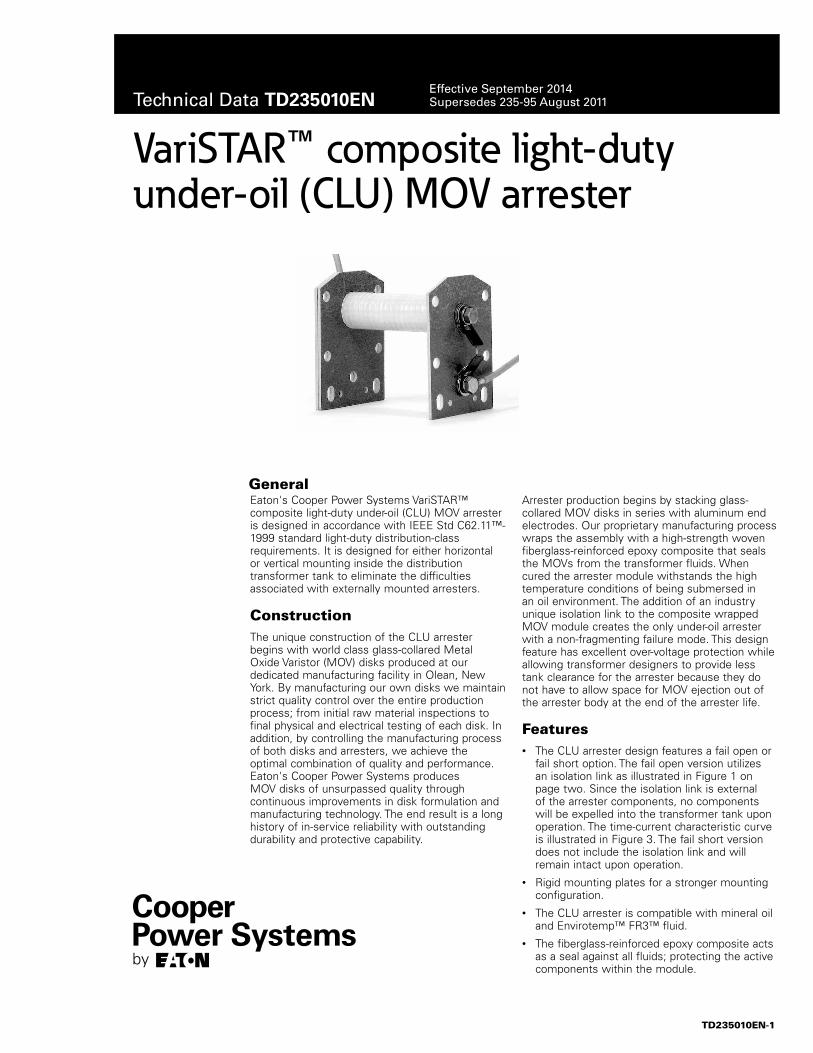
VariSTAR™ composite light-duty under-oil (CLU) MOV arrester
Eaton's Cooper Power Systems VariSTAR™ composite light-duty under-oil (CLU) MOV arrester is designed in accordance with IEEE Std C62.11™-1999 standard light-duty distribution-class requirements. It is designed for either horizontal or vertical mounting inside the distribution transformer tank to eliminate the difficulties associated with externally mounted arresters.
ConstructionThe unique construction of the CLU arrester begins with world class glass-collared Metal Oxide Varistor (MOV) disks produced at our dedicated manufacturing facility in Olean, New York. By manufacturing our own disks we maintain strict quality control over the entire production process; from initial raw material inspections to final physical and electrical testing of each disk. In addition, by controlling the manufacturing process of both disks and arresters, we achieve the optimal combination of quality and performance. Eaton's Cooper Power Systems produces MOV disks of unsurpassed quality through continuous improvements in disk formulation and manufacturing technology. The end result is a long history of in-service reliability with outstanding durability and protective capability.
Arrester production begins by stacking glass-collared MOV disks in series with aluminum end electrodes. Our proprietary manufacturing process wraps the assembly with a high-strength woven fiberglass-reinforced epoxy composite that seals the MOVs from the transformer fluids. When cured the arrester module withstands the high temperature conditions of being submersed in an oil environment. The addition of an industry unique isolation link to the composite wrapped MOV module creates the only under-oil arrester with a non-fragmenting failure mode. This design feature has excellent over-voltage protection while allowing transformer designers to provide less tank clearance for the arrester because they do not have to allow space for MOV ejection out of the arrester body at the end of the arrester life.
Features• The CLU arrester design features a fail open or
fail short option. The fail open version utilizes an isolation link as illustrated in Figure 1 on page two. Since the isolation link is external of the arrester components, no components will be expelled into the transformer tank upon operation. The time-current characteristic curve is illustrated in Figure 3. The fail short version does not include the isolation link and will remain intact upon operation.
• Rigid mounting plates for a stronger mounting configuration.
• The CLU arrester is compatible with mineral oil and Envirotemp™ FR3™ fluid.
• The fiberglass-reinforced epoxy composite acts as a seal against all fluids; protecting the active components within the module.
General
TD235010EN-1
Technical Data TD235010ENEffective September 2014Supersedes 235-95 August 2011
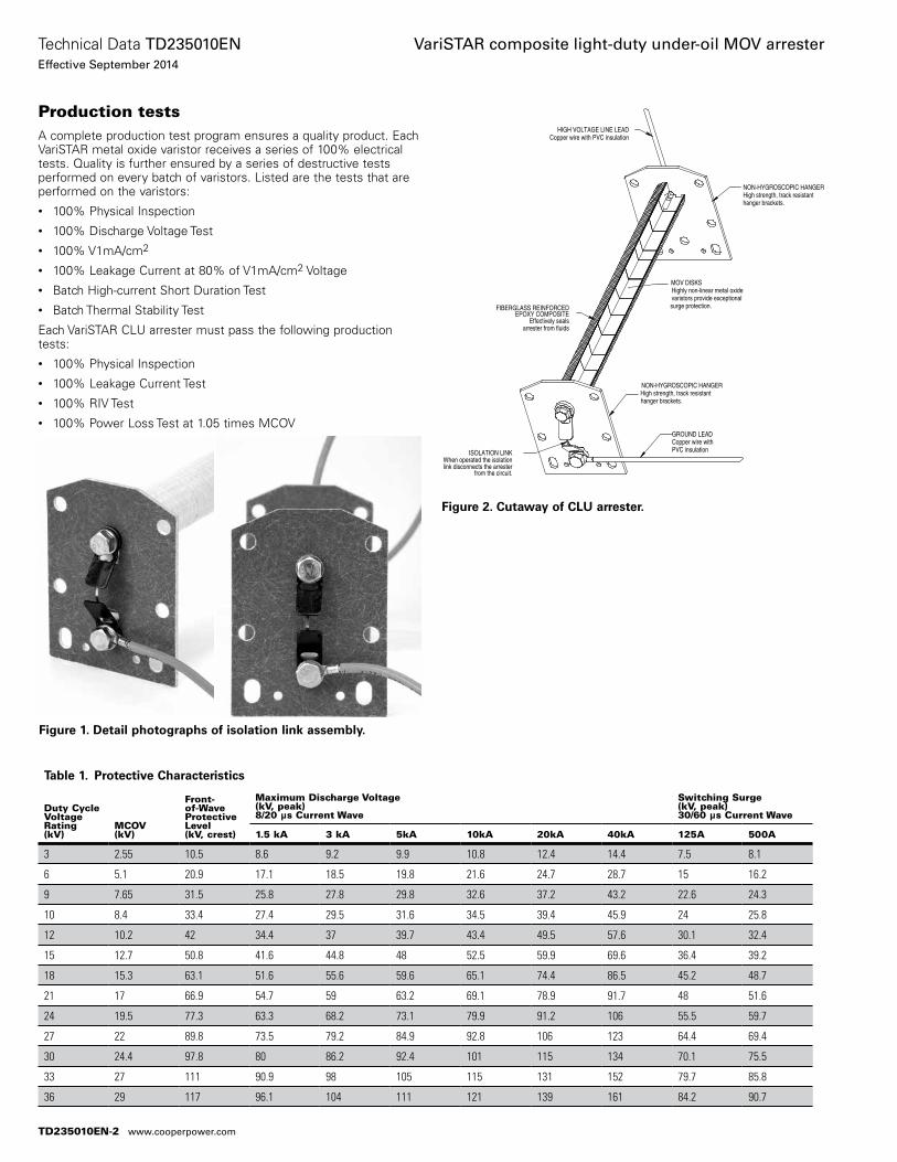
Production testsA complete production test program ensures a quality product. Each VariSTAR metal oxide varistor receives a series of 100% electrical tests. Quality is further ensured by a series of destructive tests performed on every batch of varistors. Listed are the tests that are performed on the varistors:• 100% Physical Inspection• 100% Discharge Voltage Test• 100% V1mA/cm2 • 100% Leakage Current at 80% of V1mA/cm2 Voltage• Batch High-current Short Duration Test• Batch Thermal Stability Test
Each VariSTAR CLU arrester must pass the following production tests:• 100% Physical Inspection• 100% Leakage Current Test• 100% RIV Test• 100% Power Loss Test at 1.05 times MCOV
Table 1. Protective Characteristics
Duty Cycle Voltage Rating (kV)
MCOV (kV)
Front-of-Wave Protective Level (kV, crest)
Maximum Discharge Voltage (kV, peak) 8/20 µs Current Wave
Switching Surge (kV, peak) 30/60 µs Current Wave
1.5 kA 3 kA 5kA 10kA 20kA 40kA 125A 500A
3 2.55 10.5 8.6 9.2 9.9 10.8 12.4 14.4 7.5 8.1
6 5.1 20.9 17.1 18.5 19.8 21.6 24.7 28.7 15 16.2
9 7.65 31.5 25.8 27.8 29.8 32.6 37.2 43.2 22.6 24.3
10 8.4 33.4 27.4 29.5 31.6 34.5 39.4 45.9 24 25.8
12 10.2 42 34.4 37 39.7 43.4 49.5 57.6 30.1 32.4
15 12.7 50.8 41.6 44.8 48 52.5 59.9 69.6 36.4 39.2
18 15.3 63.1 51.6 55.6 59.6 65.1 74.4 86.5 45.2 48.7
21 17 66.9 54.7 59 63.2 69.1 78.9 91.7 48 51.6
24 19.5 77.3 63.3 68.2 73.1 79.9 91.2 106 55.5 59.7
27 22 89.8 73.5 79.2 84.9 92.8 106 123 64.4 69.4
30 24.4 97.8 80 86.2 92.4 101 115 134 70.1 75.5
33 27 111 90.9 98 105 115 131 152 79.7 85.8
36 29 117 96.1 104 111 121 139 161 84.2 90.7
Figure 1. Detail photographs of isolation link assembly.
GROUND LEADCopper wire withPVC insulation
MOV DISKSHighly non-linear metal oxidevaristors provide exceptionalsurge protection.
NON-HYGROSCOPIC HANGERHigh strength, track resistanthanger brackets.
HIGH VOLTAGE LINE LEADCopper wire with PVC insulation
NON-HYGROSCOPIC HANGERHigh strength, track resistanthanger brackets.
EPOXY COMPOSITEEffectively seals
arrester from fluids
ISOLATION LINKWhen operated the isolationlink disconnects the arrester
from the circuit.
FIBERGLASS REINFORCED
Figure 2. Cutaway of CLU arrester.
TD235010EN-2
Technical Data TD235010ENEffective September 2014
VariSTAR composite light-duty under-oil MOV arrester
www.cooperpower.com
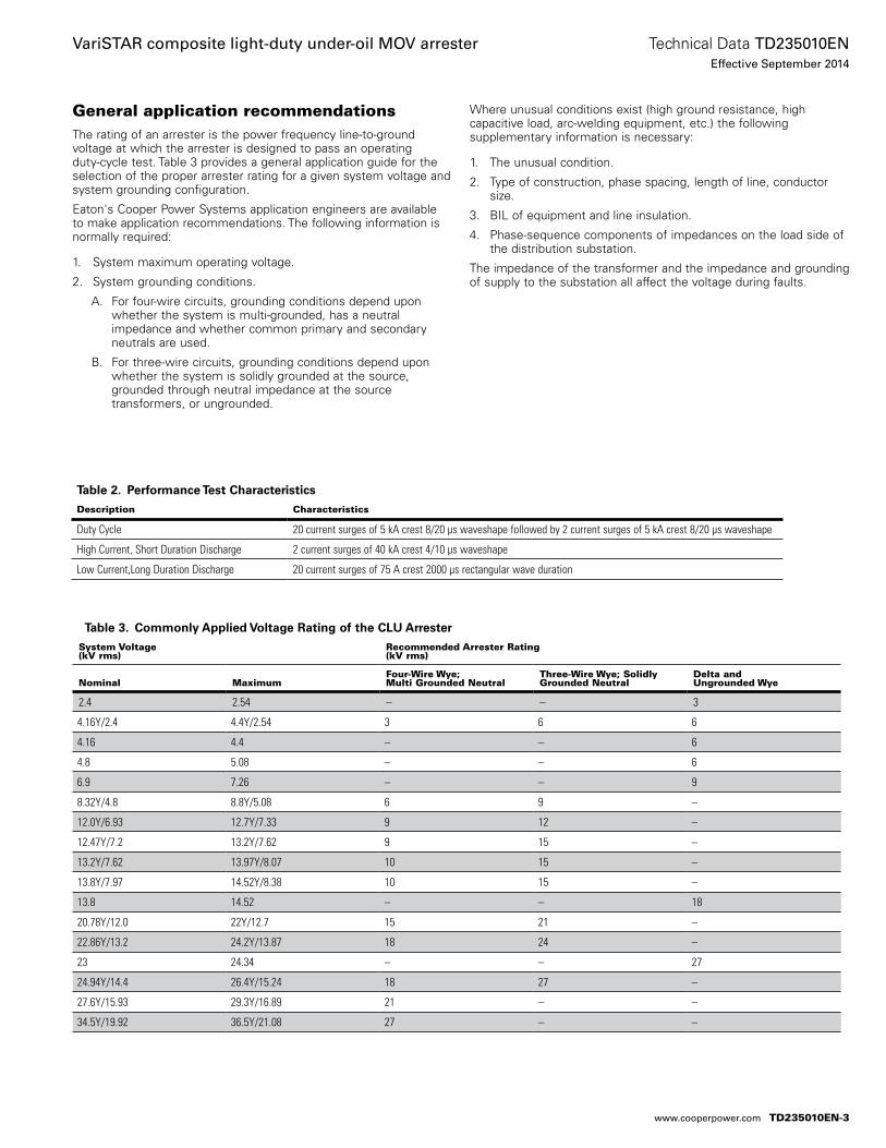
General application recommendationsThe rating of an arrester is the power frequency line-to-ground voltage at which the arrester is designed to pass an operating duty-cycle test. Table 3 provides a general application guide for the selection of the proper arrester rating for a given system voltage and system grounding configuration.
Eaton's Cooper Power Systems application engineers are available to make application recommendations. The following information is normally required:
1. System maximum operating voltage.
2. System grounding conditions.
A. For four-wire circuits, grounding conditions depend upon whether the system is multi-grounded, has a neutral impedance and whether common primary and secondary neutrals are used.
B. For three-wire circuits, grounding conditions depend upon whether the system is solidly grounded at the source, grounded through neutral impedance at the source transformers, or ungrounded.
Where unusual conditions exist (high ground resistance, high capacitive load, arc-welding equipment, etc.) the following supplementary information is necessary:
1. The unusual condition.
2. Type of construction, phase spacing, length of line, conductor size.
3. BIL of equipment and line insulation.
4. Phase-sequence components of impedances on the load side of the distribution substation.
The impedance of the transformer and the impedance and grounding of supply to the substation all affect the voltage during faults.
Table 2. Performance Test Characteristics
Description Characteristics
Duty Cycle 20 current surges of 5 kA crest 8/20 µs waveshape followed by 2 current surges of 5 kA crest 8/20 µs waveshape
High Current, Short Duration Discharge 2 current surges of 40 kA crest 4/10 µs waveshape
Low Current,Long Duration Discharge 20 current surges of 75 A crest 2000 µs rectangular wave duration
Table 3. Commonly Applied Voltage Rating of the CLU Arrester
System Voltage (kV rms)
Recommended Arrester Rating (kV rms)
Nominal MaximumFour-Wire Wye; Multi Grounded Neutral
Three-Wire Wye; Solidly Grounded Neutral
Delta and Ungrounded Wye
2.4 2.54 – – 3
4.16Y/2.4 4.4Y/2.54 3 6 6
4.16 4.4 – – 6
4.8 5.08 – – 6
6.9 7.26 – – 9
8.32Y/4.8 8.8Y/5.08 6 9 –
12.0Y/6.93 12.7Y/7.33 9 12 –
12.47Y/7.2 13.2Y/7.62 9 15 –
13.2Y/7.62 13.97Y/8.07 10 15 –
13.8Y/7.97 14.52Y/8.38 10 15 –
13.8 14.52 – – 18
20.78Y/12.0 22Y/12.7 15 21 –
22.86Y/13.2 24.2Y/13.87 18 24 –
23 24.34 – – 27
24.94Y/14.4 26.4Y/15.24 18 27 –
27.6Y/15.93 29.3Y/16.89 21 – –
34.5Y/19.92 36.5Y/21.08 27 – –
TD235010EN-3
Technical Data TD235010ENEffective September 2014
VariSTAR composite light-duty under-oil MOV arrester
www.cooperpower.com
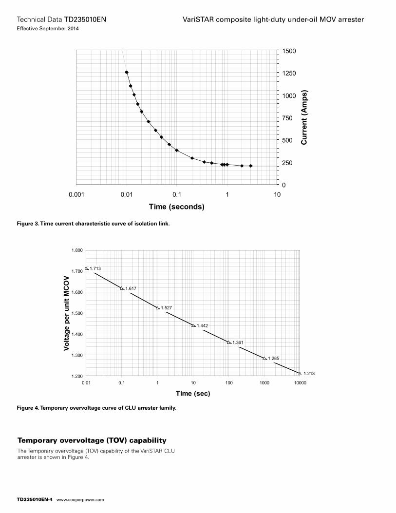
0
250
500
750
1000
1250
1500
0.001 0.01 0.1 1 10
Time (seconds)
Curr
ent (
Amps
)
Figure 3. Time current characteristic curve of isolation link.
Temporary overvoltage (TOV) capabilityThe Temporary overvoltage (TOV) capability of the VariSTAR CLU arrester is shown in Figure 4.
Figure 4. Temporary overvoltage curve of CLU arrester family.
TD235010EN-4
Technical Data TD235010ENEffective September 2014
VariSTAR composite light-duty under-oil MOV arrester
www.cooperpower.com
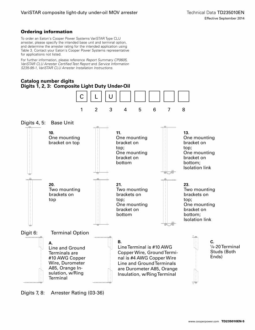
Catalog number digitsDigits 1, 2, 3: Composite Light Duty Under-Oil
C L U
1 2 3 4 5 6 7 8
Digits 4, 5: Base Unit
Digit 6: Terminal Option
Digits 7, 8: Arrester Rating (03-36)
Ordering informationTo order an Eaton's Cooper Power Systems VariSTAR Type CLU arrester, please specify the intended base unit and terminal option, and determine the arrester rating for the intended application using Table 3. Contact your Eaton's Cooper Power Systems representative for applications not listed.
For further information, please reference Report Summary CP0605, VariSTAR CLU Arrester Certified Test Report and Service Information S235-95-1, VariSTAR CLU Arrester Installation Instructions.
A.Line and Ground Terminals are #10 AWG Copper Wire, Durometer A85, Orange In-sulation, w/Ring Terminal
B.Line Terminal is #10 AWG Copper Wire, Ground Termi-nal is #4 AWG Copper Wire Line and Ground Terminals are Durometer A85, Orange Insulation, w/Ring Terminal
C.¼-20 Terminal Studs (Both Ends)
10.One mounting bracket on top
11.One mounting bracket on top; One mounting bracket on bottom
13.One mounting bracket on top; One mounting bracket on bottom; Isolation link
20.Two mounting brackets on top
21.Two mounting brackets on top; One mounting bracket on bottom
23.Two mounting brackets on top; One mounting bracket on bottom; Isolation link
TD235010EN-5
Technical Data TD235010ENEffective September 2014
VariSTAR composite light-duty under-oil MOV arrester
www.cooperpower.com
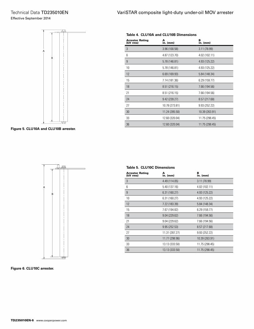
Table 4. CLU10A and CLU10B Dimensions
Arrester Rating (kV rms)
A in. (mm)
B in. (mm)
3 3.96 (100.58) 3.11 (78.99)
6 4.87 (123.70) 4.02 (102.11)
9 5.78 (146.81) 4.93 (125.22)
10 5.78 (146.81) 4.93 (125.22)
12 6.69 (169.93) 5.84 (148.34)
15 7.14 (181.36) 6.29 (159.77)
18 8.51 (216.15) 7.66 (194.56)
21 8.51 (216.15) 7.66 (194.56)
24 9.42 (239.27) 8.57 (217.68)
27 10.78 (273.81) 9.93 (252.22)
30 11.24 (285.50) 10.39 (263.91)
33 12.60 (320.04) 11.75 (298.45)
36 12.60 (320.04) 11.75 (298.45)
A
B
Figure 5. CLU10A and CLU10B arrester.
Table 5. CLU10C Dimensions
Arrester Rating (kV rms)
A in. (mm)
B in. (mm)
3 4.49 (114.05) 3.11 (78.99)
6 5.40 (137.16) 4.02 (102.11)
9 6.31 (160.27) 4.93 (125.22)
10 6.31 (160.27) 4.93 (125.22)
12 7.22 (183.39) 5.84 (148.34)
15 7.67 (194.82) 6.29 (159.77)
18 9.04 (229.62) 7.66 (194.56)
21 9.04 (229.62) 7.66 (194.56)
24 9.95 (252.53) 8.57 (217.68)
27 11.31 (287.27) 9.93 (252.22)
30 11.77 (298.96) 10.39 (263.91)
33 13.13 (333.50) 11.75 (298.45)
36 13.13 (333.50) 11.75 (298.45)
A
B
Figure 6. CLU10C arrester.
TD235010EN-6
Technical Data TD235010ENEffective September 2014
VariSTAR composite light-duty under-oil MOV arrester
www.cooperpower.com
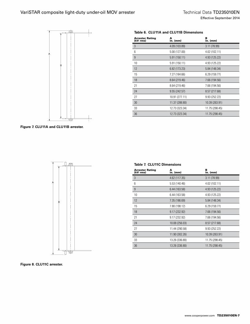
Table 6. CLU11A and CLU11B Dimensions
Arrester Rating (kV rms)
A in. (mm)
B in. (mm)
3 4.09 (103.89) 3.11 (78.99)
6 5.00 (127.00) 4.02 (102.11)
9 5.91 (150.11) 4.93 (125.22)
10 5.91 (150.11) 4.93 (125.22)
12 6.82 (173.23) 5.84 (148.34)
15 7.27 (184.66) 6.29 (159.77)
18 8.64 (219.46) 7.66 (194.56)
21 8.64 (219.46) 7.66 (194.56)
24 9.55 (242.57) 8.57 (217.68)
27 10.91 (277.11) 9.93 (252.22)
30 11.37 (288.80) 10.39 (263.91)
33 12.73 (323.34) 11.75 (298.45)
36 12.73 (323.34) 11.75 (298.45)
A
B
Figure 7. CLU11A and CLU11B arrester.
Table 7. CLU11C Dimensions
Arrester Rating (kV rms)
A in. (mm)
B in. (mm)
3 4.62 (117.35) 3.11 (78.99)
6 5.53 (140.46) 4.02 (102.11)
9 6.44 (163.58) 4.93 (125.22)
10 6.44 (163.58) 4.93 (125.22)
12 7.35 (186.69) 5.84 (148.34)
15 7.80 (198.12) 6.29 (159.77)
18 9.17 (232.92) 7.66 (194.56)
21 9.17 (232.92) 7.66 (194.56)
24 10.08 (256.03) 8.57 (217.68)
27 11.44 (290.58) 9.93 (252.22)
30 11.90 (302.26) 10.39 (263.91)
33 13.26 (336.80) 11.75 (298.45)
36 13.26 (336.80) 11.75 (298.45)
A
B
Figure 8. CLU11C arrester.
TD235010EN-7
Technical Data TD235010ENEffective September 2014
VariSTAR composite light-duty under-oil MOV arrester
www.cooperpower.com
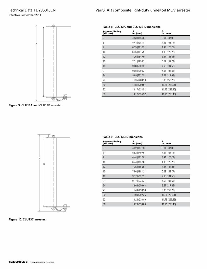
Table 8. CLU13A and CLU13B Dimensions
Arrester Rating (kV rms)
A in. (mm)
B in. (mm)
3 4.53 (115.06) 3.11 (78.99)
6 5.44 (138.18) 4.02 (102.11)
9 6.35 (161.29) 4.93 (125.22)
10 6.35 (161.29) 4.93 (125.22)
12 7.26 (184.40) 5.84 (148.34)
15 7.71 (195.83) 6.29 (159.77)
18 9.08 (230.63) 7.66 (194.56)
21 9.08 (230.63) 7.66 (194.56)
24 9.99 (253.75) 8.57 (217.68)
27 11.35 (288.29) 9.93 (252.22)
30 11.81 (299.97) 10.39 (263.91)
33 13.17 (334.52) 11.75 (298.45)
36 13.17 (334.52) 11.75 (298.45)
A
B
Figure 9. CLU13A and CLU13B arrester.
Table 9. CLU13C Dimensions
Arrester Rating (kV rms)
A in. (mm)
B in. (mm)
3 4.62 (117.35) 3.11 (78.99)
6 5.53 (140.46) 4.02 (102.11)
9 6.44 (163.58) 4.93 (125.22)
10 6.44 (163.58) 4.93 (125.22)
12 7.35 (186.69) 5.84 (148.34)
15 7.80 (198.12) 6.29 (159.77)
18 9.17 (232.92) 7.66 (194.56)
21 9.17 (232.92) 7.66 (194.56)
24 10.08 (256.03) 8.57 (217.68)
27 11.44 (290.58) 9.93 (252.22)
30 11.90 (302.26) 10.39 (263.91)
33 13.26 (336.80) 11.75 (298.45)
36 13.26 (336.80) 11.75 (298.45)
A
B
Figure 10. CLU13C arrester.
TD235010EN-8
Technical Data TD235010ENEffective September 2014
VariSTAR composite light-duty under-oil MOV arrester
www.cooperpower.com
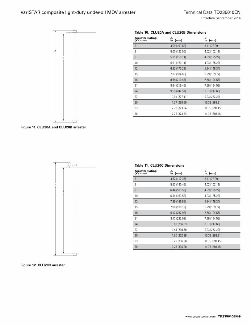
Table 10. CLU20A and CLU20B Dimensions
Arrester Rating (kV rms)
A in. (mm)
B in. (mm)
3 4.09 (103.89) 3.11 (78.99)
6 5.00 (127.00) 4.02 (102.11)
9 5.91 (150.11) 4.93 (125.22)
10 5.91 (150.11) 4.93 (125.22)
12 6.82 (173.23) 5.84 (148.34)
15 7.27 (184.66) 6.29 (159.77)
18 8.64 (219.46) 7.66 (194.56)
21 8.64 (219.46) 7.66 (194.56)
24 9.55 (242.57) 8.57 (217.68)
27 10.91 (277.11) 9.93 (252.22)
30 11.37 (288.80) 10.39 (263.91)
33 12.73 (323.34) 11.75 (298.45)
36 12.73 (323.34) 11.75 (298.45)
A
B
Figure 11. CLU20A and CLU20B arrester.
Table 11. CLU20C Dimensions
Arrester Rating (kV rms)
A in. (mm)
B in. (mm)
3 4.62 (117.35) 3.11 (78.99)
6 5.53 (140.46) 4.02 (102.11)
9 6.44 (163.58) 4.93 (125.22)
10 6.44 (163.58) 4.93 (125.22)
12 7.35 (186.69) 5.84 (148.34)
15 7.80 (198.12) 6.29 (159.77)
18 9.17 (232.92) 7.66 (194.56)
21 9.17 (232.92) 7.66 (194.56)
24 10.08 (256.03) 8.57 (217.68)
27 11.44 (290.58) 9.93 (252.22)
30 11.90 (302.26) 10.39 (263.91)
33 13.26 (336.80) 11.75 (298.45)
36 13.26 (336.80) 11.75 (298.45)
A
B
Figure 12. CLU20C arrester.
TD235010EN-9
Technical Data TD235010ENEffective September 2014
VariSTAR composite light-duty under-oil MOV arrester
www.cooperpower.com
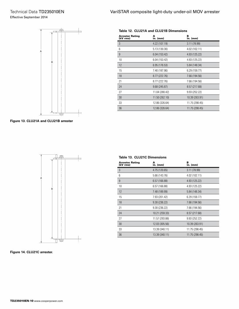
Table 12. CLU21A and CLU21B Dimensions
Arrester Rating (kV rms)
A in. (mm)
B in. (mm)
3 4.22 (107.19) 3.11 (78.99)
6 5.13 (130.30) 4.02 (102.11)
9 6.04 (153.42) 4.93 (125.22)
10 6.04 (153.42) 4.93 (125.22)
12 6.95 (176.53) 5.84 (148.34)
15 7.40 (187.96) 6.29 (159.77)
18 8.77 (222.76) 7.66 (194.56)
21 8.77 (222.76) 7.66 (194.56)
24 9.68 (245.87) 8.57 (217.68)
27 11.04 (280.42) 9.93 (252.22)
30 11.50 (262.10) 10.39 (263.91)
33 12.86 (326.64) 11.75 (298.45)
36 12.86 (326.64) 11.75 (298.45)
A
B
Figure 13. CLU21A and CLU21B arrester
Table 13. CLU21C Dimensions
Arrester Rating (kV rms)
A in. (mm)
B in. (mm)
3 4.75 (120.65) 3.11 (78.99)
6 5.66 (143.76) 4.02 (102.11)
9 6.57 (166.88) 4.93 (125.22)
10 6.57 (166.88) 4.93 (125.22)
12 7.48 (189.99) 5.84 (148.34)
15 7.93 (201.42) 6.29 (159.77)
18 9.30 (236.22) 7.66 (194.56)
21 9.30 (236.22) 7.66 (194.56)
24 10.21 (259.33) 8.57 (217.68)
27 11.57 (293.88) 9.93 (252.22)
30 12.03 (305.56) 10.39 (263.91)
33 13.39 (340.11) 11.75 (298.45)
36 13.39 (340.11) 11.75 (298.45)
A
B
Figure 14. CLU21C arrester.
TD235010EN-10
Technical Data TD235010ENEffective September 2014
VariSTAR composite light-duty under-oil MOV arrester
www.cooperpower.com
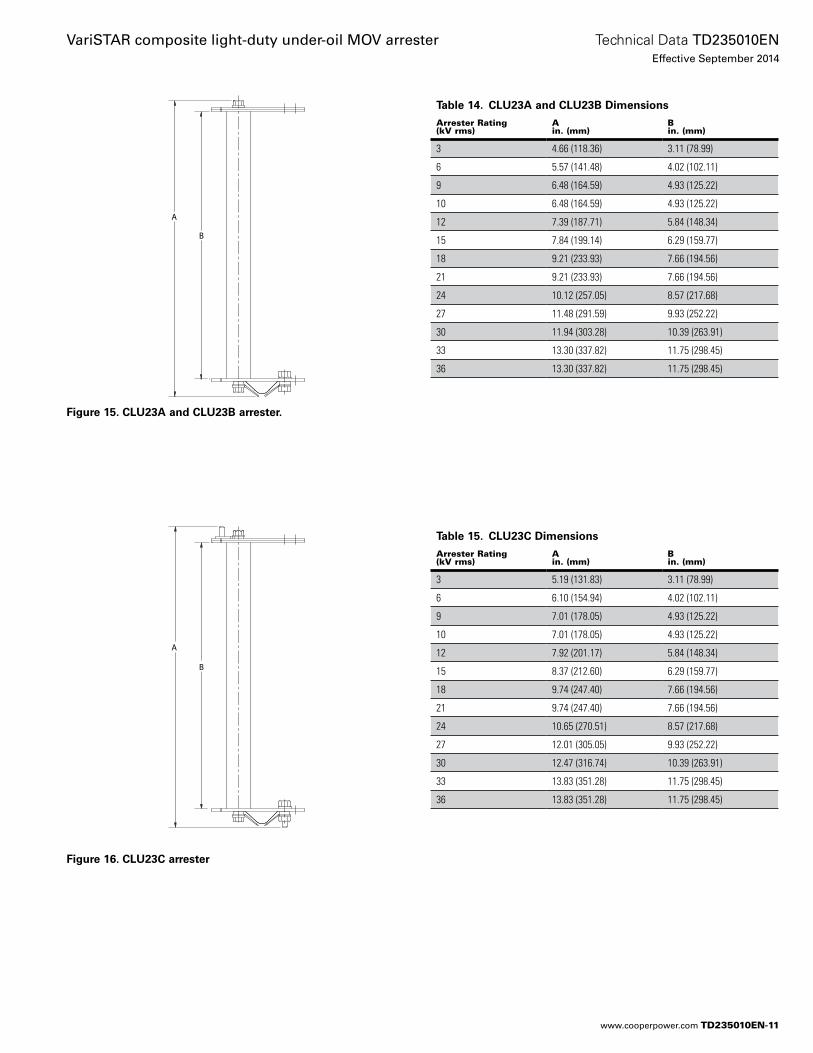
Table 12. CLU21A and CLU21B Dimensions
Arrester Rating (kV rms)
A in. (mm)
B in. (mm)
3 4.22 (107.19) 3.11 (78.99)
6 5.13 (130.30) 4.02 (102.11)
9 6.04 (153.42) 4.93 (125.22)
10 6.04 (153.42) 4.93 (125.22)
12 6.95 (176.53) 5.84 (148.34)
15 7.40 (187.96) 6.29 (159.77)
18 8.77 (222.76) 7.66 (194.56)
21 8.77 (222.76) 7.66 (194.56)
24 9.68 (245.87) 8.57 (217.68)
27 11.04 (280.42) 9.93 (252.22)
30 11.50 (262.10) 10.39 (263.91)
33 12.86 (326.64) 11.75 (298.45)
36 12.86 (326.64) 11.75 (298.45)
Table 14. CLU23A and CLU23B Dimensions
Arrester Rating (kV rms)
A in. (mm)
B in. (mm)
3 4.66 (118.36) 3.11 (78.99)
6 5.57 (141.48) 4.02 (102.11)
9 6.48 (164.59) 4.93 (125.22)
10 6.48 (164.59) 4.93 (125.22)
12 7.39 (187.71) 5.84 (148.34)
15 7.84 (199.14) 6.29 (159.77)
18 9.21 (233.93) 7.66 (194.56)
21 9.21 (233.93) 7.66 (194.56)
24 10.12 (257.05) 8.57 (217.68)
27 11.48 (291.59) 9.93 (252.22)
30 11.94 (303.28) 10.39 (263.91)
33 13.30 (337.82) 11.75 (298.45)
36 13.30 (337.82) 11.75 (298.45)
A
B
Figure 15. CLU23A and CLU23B arrester.
Table 15. CLU23C Dimensions
Arrester Rating (kV rms)
A in. (mm)
B in. (mm)
3 5.19 (131.83) 3.11 (78.99)
6 6.10 (154.94) 4.02 (102.11)
9 7.01 (178.05) 4.93 (125.22)
10 7.01 (178.05) 4.93 (125.22)
12 7.92 (201.17) 5.84 (148.34)
15 8.37 (212.60) 6.29 (159.77)
18 9.74 (247.40) 7.66 (194.56)
21 9.74 (247.40) 7.66 (194.56)
24 10.65 (270.51) 8.57 (217.68)
27 12.01 (305.05) 9.93 (252.22)
30 12.47 (316.74) 10.39 (263.91)
33 13.83 (351.28) 11.75 (298.45)
36 13.83 (351.28) 11.75 (298.45)
A
B
Figure 16. CLU23C arrester
TD235010EN-11
Technical Data TD235010ENEffective September 2014
VariSTAR composite light-duty under-oil MOV arrester
www.cooperpower.com
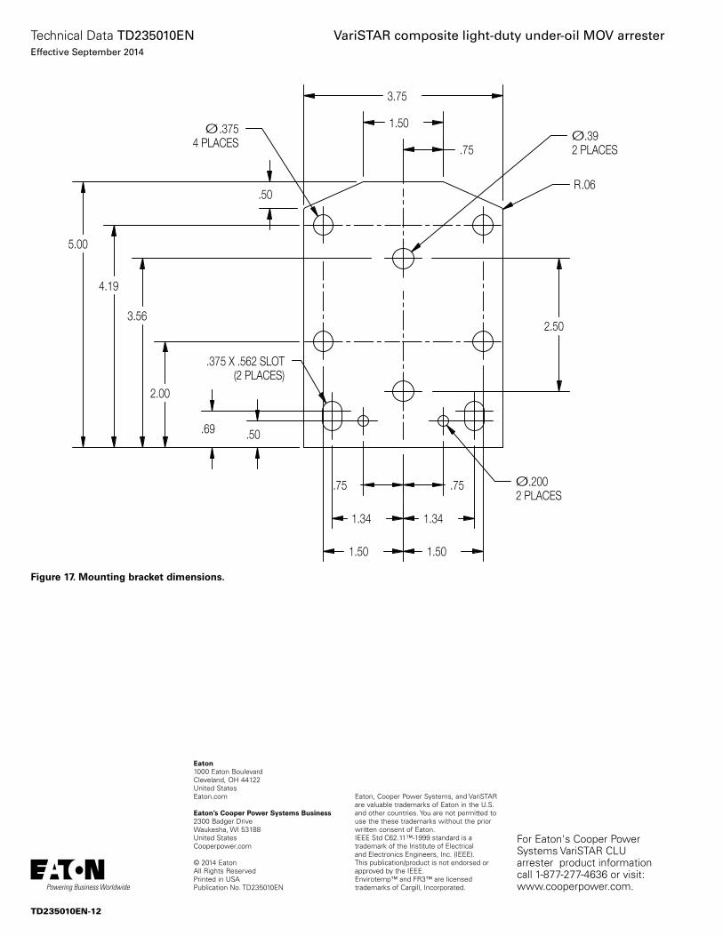
.75
5.00
3.75
3.56
1.50
.50R.06
Ø2 PLACES
.39
2.50
Ø2 PLACES
.200.75.75
.50
1.50 1.50
1.34 1.34
4.19
Ø4 PLACES
.375
2.00
.69
.375 X .562 SLOT(2 PLACES)
Figure 17. Mounting bracket dimensions.
Eaton, Cooper Power Systems, and VariSTAR are valuable trademarks of Eaton in the U.S. and other countries. You are not permitted to use the these trademarks without the prior written consent of Eaton.IEEE Std C62.11™-1999 standard is a trademark of the Institute of Electrical and Electronics Engineers, Inc. (IEEE). This publication/product is not endorsed or approved by the IEEE.Envirotemp™ and FR3™ are licensed trademarks of Cargill, Incorporated.
VariSTAR composite light-duty under-oil MOV arrester
Eaton1000 Eaton BoulevardCleveland, OH 44122United StatesEaton.com
Eaton’s Cooper Power Systems Business2300 Badger DriveWaukesha, WI 53188United StatesCooperpower.com
© 2014 EatonAll Rights ReservedPrinted in USAPublication No. TD235010EN
Technical Data TD235010ENEffective September 2014
For Eaton's Cooper Power Systems VariSTAR CLU arrester product information call 1-877-277-4636 or visit: www.cooperpower.com.
TD235010EN-12
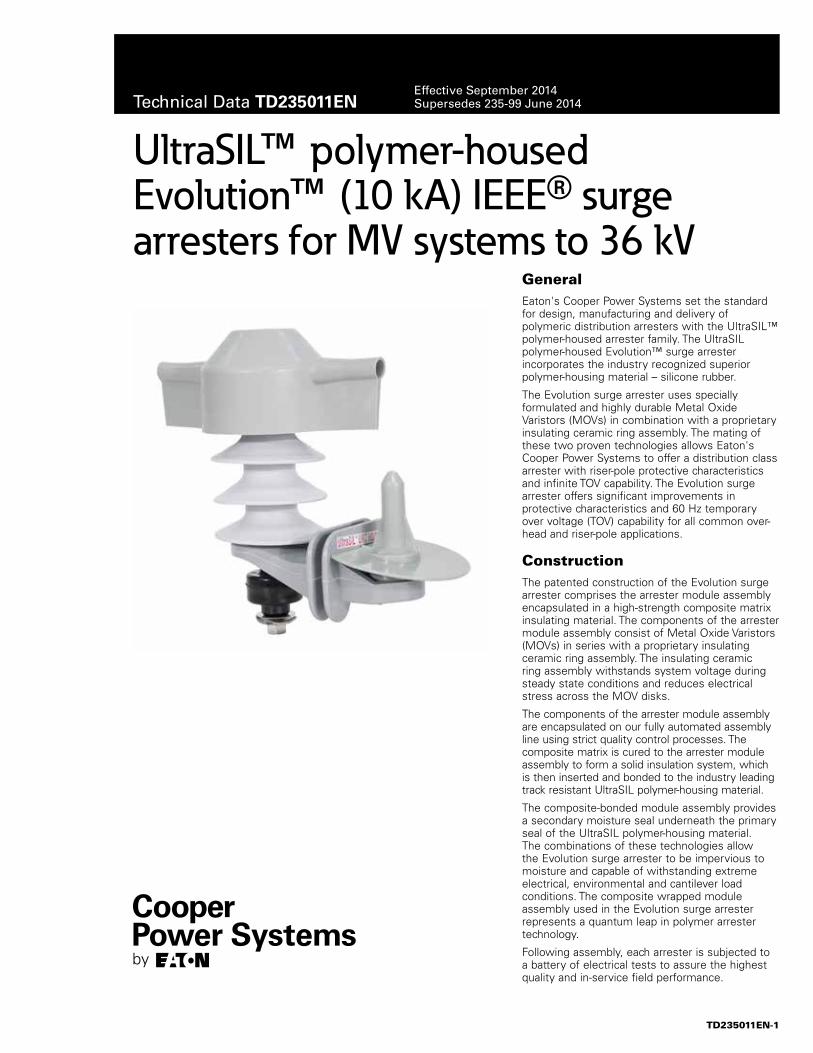
GeneralEaton's Cooper Power Systems set the standard for design, manufacturing and delivery of polymeric distribution arresters with the UltraSIL™ polymer-housed arrester family. The UltraSIL polymer-housed Evolution™ surge arrester incorporates the industry recognized superior polymer-housing material – silicone rubber.
The Evolution surge arrester uses specially formulated and highly durable Metal Oxide Varistors (MOVs) in combination with a proprietary insulating ceramic ring assembly. The mating of these two proven technologies allows Eaton's Cooper Power Systems to offer a distribution class arrester with riser-pole protective characteristics and infinite TOV capability. The Evolution surge arrester offers significant improvements in protective characteristics and 60 Hz temporary over voltage (TOV) capability for all common over-head and riser-pole applications.
ConstructionThe patented construction of the Evolution surge arrester comprises the arrester module assembly encapsulated in a high-strength composite matrix insulating material. The components of the arrester module assembly consist of Metal Oxide Varistors (MOVs) in series with a proprietary insulating ceramic ring assembly. The insulating ceramic ring assembly withstands system voltage during steady state conditions and reduces electrical stress across the MOV disks.
The components of the arrester module assembly are encapsulated on our fully automated assembly line using strict quality control processes. The composite matrix is cured to the arrester module assembly to form a solid insulation system, which is then inserted and bonded to the industry leading track resistant UltraSIL polymer-housing material.
The composite-bonded module assembly provides a secondary moisture seal underneath the primary seal of the UltraSIL polymer-housing material. The combinations of these technologies allow the Evolution surge arrester to be impervious to moisture and capable of withstanding extreme electrical, environmental and cantilever load conditions. The composite wrapped module assembly used in the Evolution surge arrester represents a quantum leap in polymer arrester technology.
Following assembly, each arrester is subjected to a battery of electrical tests to assure the highest quality and in-service field performance.
UltraSIL™ polymer-housed Evolution™ (10 kA) IEEE® surge arresters for MV systems to 36 kV
TD235011EN-1
Technical Data TD235011ENEffective September 2014Supersedes 235-99 June 2014
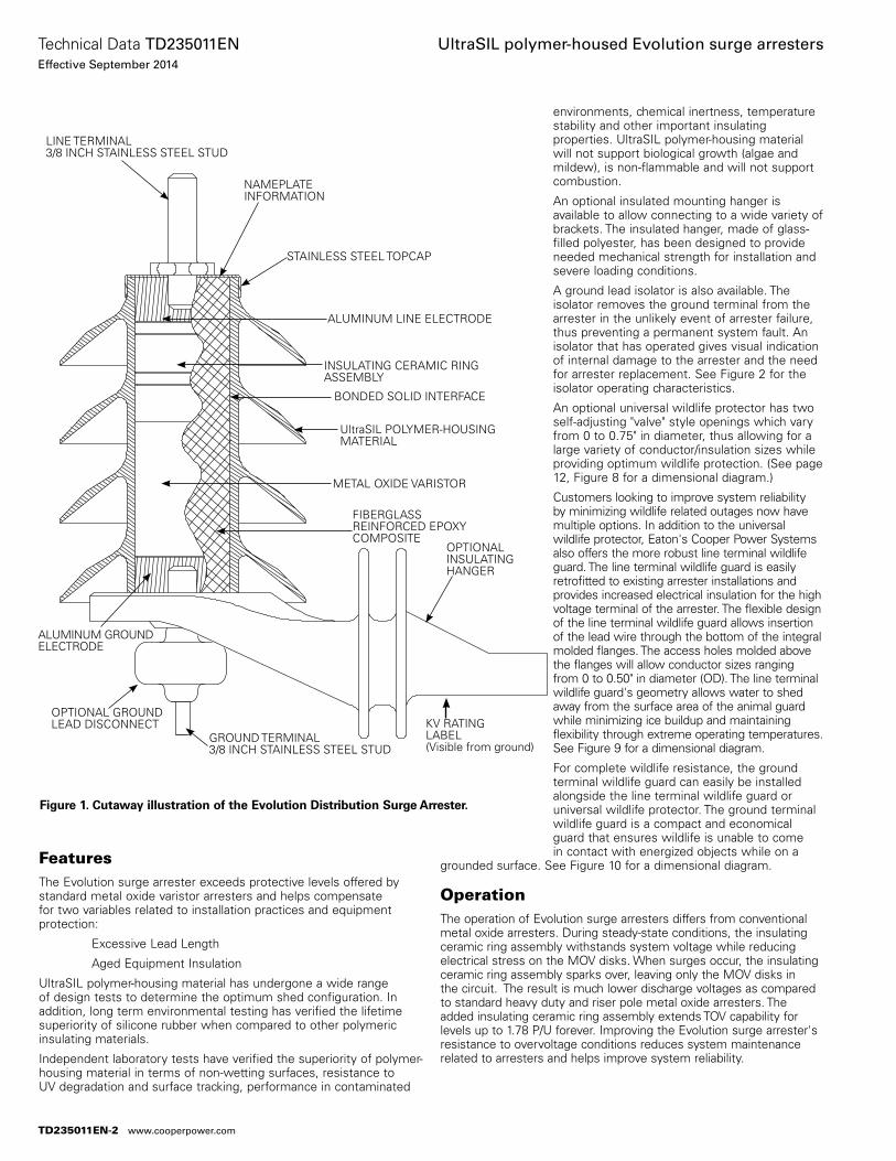
FeaturesThe Evolution surge arrester exceeds protective levels offered by standard metal oxide varistor arresters and helps compensate for two variables related to installation practices and equipment protection:
Excessive Lead Length
Aged Equipment Insulation
UltraSIL polymer-housing material has undergone a wide range of design tests to determine the optimum shed configuration. In addition, long term environmental testing has verified the lifetime superiority of silicone rubber when compared to other polymeric insulating materials.
Independent laboratory tests have verified the superiority of polymer-housing material in terms of non-wetting surfaces, resistance to UV degradation and surface tracking, performance in contaminated
environments, chemical inertness, temperature stability and other important insulating properties. UltraSIL polymer-housing material will not support biological growth (algae and mildew), is non-flammable and will not support combustion.
An optional insulated mounting hanger is available to allow connecting to a wide variety of brackets. The insulated hanger, made of glass-filled polyester, has been designed to provide needed mechanical strength for installation and severe loading conditions.
A ground lead isolator is also available. The isolator removes the ground terminal from the arrester in the unlikely event of arrester failure, thus preventing a permanent system fault. An isolator that has operated gives visual indication of internal damage to the arrester and the need for arrester replacement. See Figure 2 for the isolator operating characteristics.
An optional universal wildlife protector has two self-adjusting "valve" style openings which vary from 0 to 0.75" in diameter, thus allowing for a large variety of conductor/insulation sizes while providing optimum wildlife protection. (See page 12, Figure 8 for a dimensional diagram.)
Customers looking to improve system reliability by minimizing wildlife related outages now have multiple options. In addition to the universal wildlife protector, Eaton's Cooper Power Systems also offers the more robust line terminal wildlife guard. The line terminal wildlife guard is easily retrofitted to existing arrester installations and provides increased electrical insulation for the high voltage terminal of the arrester. The flexible design of the line terminal wildlife guard allows insertion of the lead wire through the bottom of the integral molded flanges. The access holes molded above the flanges will allow conductor sizes ranging from 0 to 0.50" in diameter (OD). The line terminal wildlife guard's geometry allows water to shed away from the surface area of the animal guard while minimizing ice buildup and maintaining flexibility through extreme operating temperatures. See Figure 9 for a dimensional diagram.
For complete wildlife resistance, the ground terminal wildlife guard can easily be installed alongside the line terminal wildlife guard or universal wildlife protector. The ground terminal wildlife guard is a compact and economical guard that ensures wildlife is unable to come in contact with energized objects while on a
grounded surface. See Figure 10 for a dimensional diagram.
OperationThe operation of Evolution surge arresters differs from conventional metal oxide arresters. During steady-state conditions, the insulating ceramic ring assembly withstands system voltage while reducing electrical stress on the MOV disks. When surges occur, the insulating ceramic ring assembly sparks over, leaving only the MOV disks in the circuit. The result is much lower discharge voltages as compared to standard heavy duty and riser pole metal oxide arresters. The added insulating ceramic ring assembly extends TOV capability for levels up to 1.78 P/U forever. Improving the Evolution surge arrester's resistance to overvoltage conditions reduces system maintenance related to arresters and helps improve system reliability.
Figure 1. Cutaway illustration of the Evolution Distribution Surge Arrester.
STAINLESS STEEL TOPCAP
NAMEPLATEINFORMATION
ALUMINUM LINE ELECTRODE
INSULATING CERAMIC RING ASSEMBLY
BONDED SOLID INTERFACE
UltraSIL POLYMER-HOUSING MATERIAL
METAL OXIDE VARISTOR
FIBERGLASS REINFORCED EPOXY COMPOSITE
OPTIONAL INSULATING HANGER
LINE TERMINAL3/8 INCH STAINLESS STEEL STUD
ALUMINUM GROUND ELECTRODE
OPTIONAL GROUND LEAD DISCONNECT KV RATING
LABEL(Visible from ground)
GROUND TERMINAL3/8 INCH STAINLESS STEEL STUD
TD235011EN-2
Technical Data TD235011ENEffective September 2014
UltraSIL polymer-housed Evolution surge arresters
www.cooperpower.com
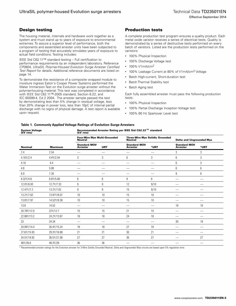
Design testingThe housing material, internals and hardware work together as a system and must stand up to years of exposure to environmental extremes. To assure a superior level of performance, both the components and assembled arrester units have been subjected to a program of testing that accurately simulates years of exposure to actual field conditions. Testing includes:
IEEE Std C62.11™ standard testing – Full certification to performance requirements by an independent laboratory. Reference CP0804, UltraSIL Polymer-Housed Evolution Surge Arrester Certified Test Report for details. Additional reference documents are listed on page 14.
To demonstrate the resistance of a composite wrapped module to moisture ingress Eaton's Cooper Power Systems performed the Water Immersion Test on the Evolution surge arrester without the polymer-housing material. This test was completed in accordance with IEEE Std C62.11™-2005 standard, Section 8.22, and IEC 60099-4, Ed 2 2004. The arrester sample passed the test by demonstrating less than 5% change in residual voltage, less than 20% change in power loss, less than 10pC of internal partial discharge with no signs of physical damage. A test report is available upon request.
Production testsA complete production test program ensures a quality product. Each metal oxide varistor receives a series of electrical tests. Quality is demonstrated by a series of destructive tests performed on every batch of varistors. Listed are the production tests performed on the varistors:• 100% Physical Inspection• 100% Discharge Voltage test• 100% V1mA/cm2
• 100% Leakage Current at 80% of V1mA/cm2 Voltage• Batch High-current, Short-duration test• Batch Thermal Stability test• Batch Aging test
Each fully assembled arrester must pass the following production tests:• 100% Physical Inspection• 100% Partial Discharge Inception Voltage test• 100% 60 Hz Sparkover Level test
Table 1. Commonly Applied Voltage Ratings of Evolution Surge Arresters
System Voltage(kV rms)
Recommended Arrester Rating per IEEE Std C62.22™ standard(kV rms)
Nominal Maximum
Four-Wire Wye Multi-Grounded Neutral
Three-Wire Wye Solidly Grounded Neutral Delta and Ungrounded Wye
Standard MOV Arrester URT
Standard MOV Arrester *URT
Standard MOV Arrester *URT
2.4 2.54 — — — — 3 3
4.16Y/2.4 4.4Y/2.54 3 3 6 3 6 3
4.16 4.4 — — — — 6 3
4.8 5.08 — — — — 6 6
6.9 7.26 — — — — 9 6
8.32Y/4.8 8.8Y/5.08 6 6 9 6 — —
12.0Y/6.93 12.7Y/7.33 9 9 12 9/10 — —
12.47Y/7.2 13.2Y/7.62 9 9 15 9/10 — —
13.2Y/7.62 13.97Y/8.07 10 10 15 10 — —
13.8Y/7.97 14.52Y/8.38 10 10 15 10 –– —
13.8 14.52 — — — — 18 10
20.78Y/12.0 22Y/12.7 15 15 21 15 — —
22.86Y/13.2 24.2Y/13.87 18 18 24 18 — —
23 24.34 — — — — 30 18
24.94Y/14.4 26.4Y/15.24 18 18 27 18 — —
27.6Y/15.93 29.3Y/16.89 21 21 30 21 — —
34.5Y/19.92 36.5Y/21.08 27 27 36 27 — 27
46Y/26.6 48.3Y/28 36 36 — — — —* Recommended arrester ratings for the Evolution arrester for 3-Wire Solidly Grounded Neutral, Delta and Ungrounded Wye circuits are based upon 5% regulation error.
TD235011EN-3
Technical Data TD235011ENEffective September 2014
UltraSIL polymer-housed Evolution surge arresters
www.cooperpower.com
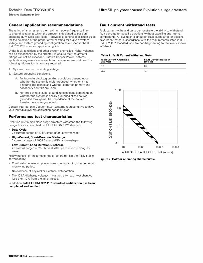
General application recommendationsThe rating of an arrester is the maximum power frequency line-to-ground voltage at which the arrester is designed to pass an operating duty-cycle test. Table 1 provides a general application guide for the selection of the proper arrester rating for a given system voltage and system grounding configuration as outlined in the IEEE Std C62.22™ standard application guide.
Under fault conditions and other system anomalies, higher voltages can be experienced by the arrester. To ensure that the arrester ratings will not be exceeded, Eaton's Cooper Power Systems application engineers are available to make recommendations. The following information is normally required:
1. System maximum operating voltage.
2. System grounding conditions.
A. For four-wire circuits, grounding conditions depend upon whether the system is multi-grounded, whether it has a neutral impedance and whether common primary and secondary neutrals are used.
B. For three-wire circuits, grounding conditions depend upon whether the system is solidly grounded at the source, grounded through neutral impedance at the source transformers or ungrounded.
Consult your Eaton's Cooper Power Systems representative to have your individual system application needs studied.
Performance test characteristicsEvolution distribution class surge arresters withstand the following design tests as described by IEEE Std C62.11™ standard:• Duty Cycle:
22 current surges of 10 kA crest, 8/20 µs waveshape.• High-Current, Short-Duration Discharge:
2 current surges of 100 kA crest, 4/10 µs waveshape.• Low-Current, Long-Duration Discharge:
20 current surges of 250 A crest 2000 µs duration rectangular wave.
Following each of these tests, the arresters remain thermally stable as verified by:• Continually decreasing power values during a thirty minute power
monitoring period.• No evidence of physical or electrical deterioration.• The 10 kA discharge voltages measured after each test changed
less then 10% from the initial values.
In addition, full IEEE Std C62.11™ standard certification has been completed and verified.
Fault current withstand testsFault current withstand tests demonstrate the ability to withstand fault currents for specific durations without expelling any internal components. All Evolution distribution class surge arrester designs have been tested in accordance with the requirements listed in IEEE Std C62.11™ standard, and are non-fragmenting to the levels shown in Table 2.
Table 2. Fault Current Withstand Tests
Fault Current Amplitude(kA rms)
Fault Current Duration(cycles)
0.6 60
20.0 12
10.0
1.0
0.1
0.0110 100 1000 10000
ARRESTER FAULT CURRENT (A rms)
IGN
ITIO
N T
IME
(SE
CO
ND
S)
Figure 2. Isolator operating characteristic.
TD235011EN-4
Technical Data TD235011ENEffective September 2014
UltraSIL polymer-housed Evolution surge arresters
www.cooperpower.com
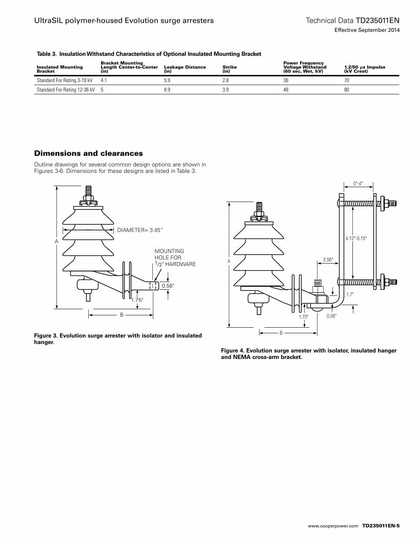
Dimensions and clearancesOutline drawings for several common design options are shown in Figures 3-6. Dimensions for these designs are listed in Table 3.
Figure 3. Evolution surge arrester with isolator and insulated hanger.
A
B
DIAMETER= 3.45”
MOUNTING HOLE FOR 1/2" HARDWARE
0.56"
1.75"
Figure 4. Evolution surge arrester with isolator, insulated hanger and NEMA cross-arm bracket.
A
0.56"
2.56"
1.7"
4.12"-5.15"
B
0"-4"
1.75"
Table 3. Insulation Withstand Characteristics of Optional Insulated Mounting Bracket
Insulated Mounting Bracket
Bracket Mounting Length Center-to-Center (in)
Leakage Distance(in)
Strike (in)
Power Frequency Voltage Withstand (60 sec, Wet, kV)
1.2/50 μs Impulse (kV Crest)
Standard For Rating 3-10 kV 4.1 5.9 2.8 36 70
Standard For Rating 12-36 kV 5 8.9 3.9 48 80
TD235011EN-5
Technical Data TD235011ENEffective September 2014
UltraSIL polymer-housed Evolution surge arresters
www.cooperpower.com
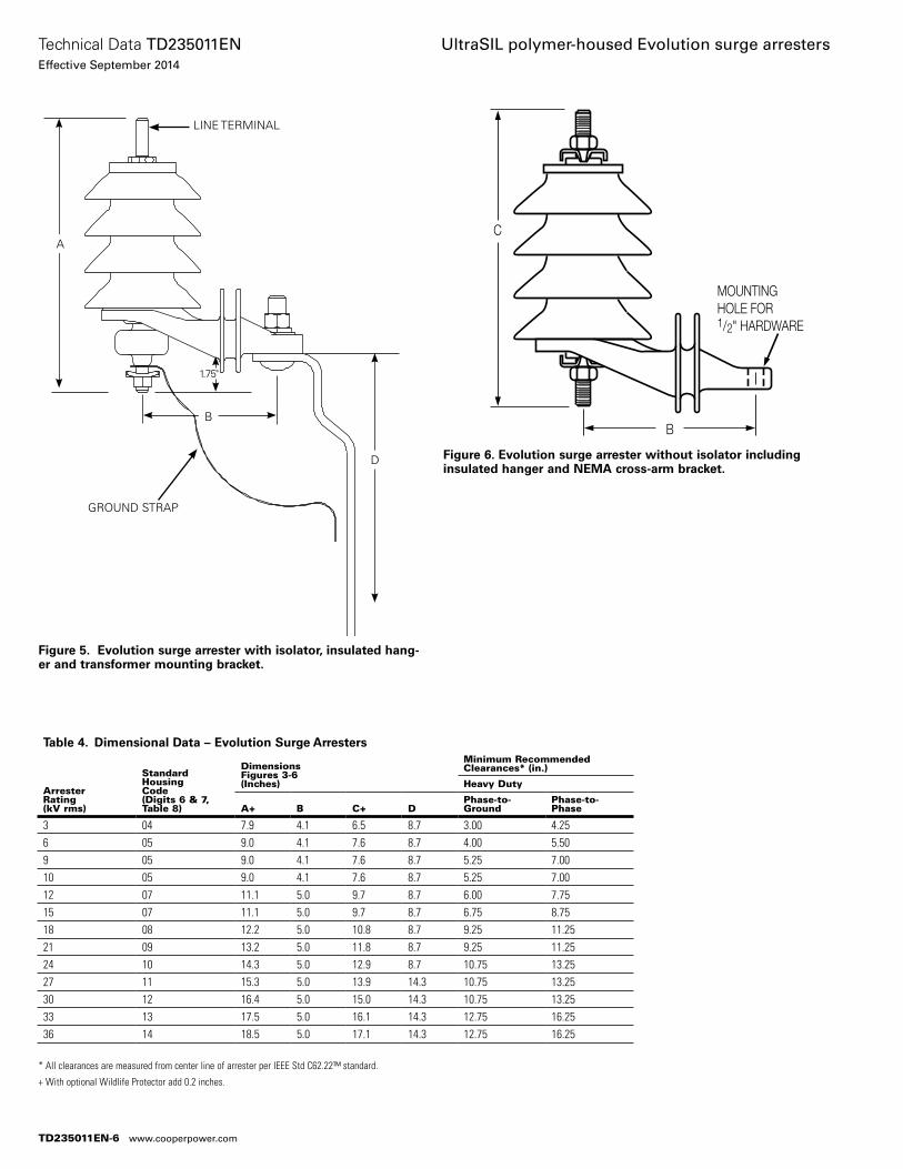
Figure 5. Evolution surge arrester with isolator, insulated hang-er and transformer mounting bracket.
GROUND STRAP
LINE TERMINAL
D
A
B
Figure 6. Evolution surge arrester without isolator including insulated hanger and NEMA cross-arm bracket.
C
B
MOUNTING HOLE FOR 1/2" HARDWARE
* All clearances are measured from center line of arrester per IEEE Std C62.22™ standard.
+ With optional Wildlife Protector add 0.2 inches.
Table 4. Dimensional Data – Evolution Surge Arresters
ArresterRating(kV rms)
StandardHousingCode(Digits 6 & 7, Table 8)
DimensionsFigures 3-6(Inches)
Minimum Recommended Clearances* (in.)
Heavy Duty
A+ B C+ DPhase-to-Ground
Phase-to-Phase
3 04 7.9 4.1 6.5 8.7 3.00 4.256 05 9.0 4.1 7.6 8.7 4.00 5.509 05 9.0 4.1 7.6 8.7 5.25 7.0010 05 9.0 4.1 7.6 8.7 5.25 7.0012 07 11.1 5.0 9.7 8.7 6.00 7.7515 07 11.1 5.0 9.7 8.7 6.75 8.7518 08 12.2 5.0 10.8 8.7 9.25 11.2521 09 13.2 5.0 11.8 8.7 9.25 11.2524 10 14.3 5.0 12.9 8.7 10.75 13.2527 11 15.3 5.0 13.9 14.3 10.75 13.2530 12 16.4 5.0 15.0 14.3 10.75 13.2533 13 17.5 5.0 16.1 14.3 12.75 16.2536 14 18.5 5.0 17.1 14.3 12.75 16.25
1.75"
TD235011EN-6
Technical Data TD235011ENEffective September 2014
UltraSIL polymer-housed Evolution surge arresters
www.cooperpower.com
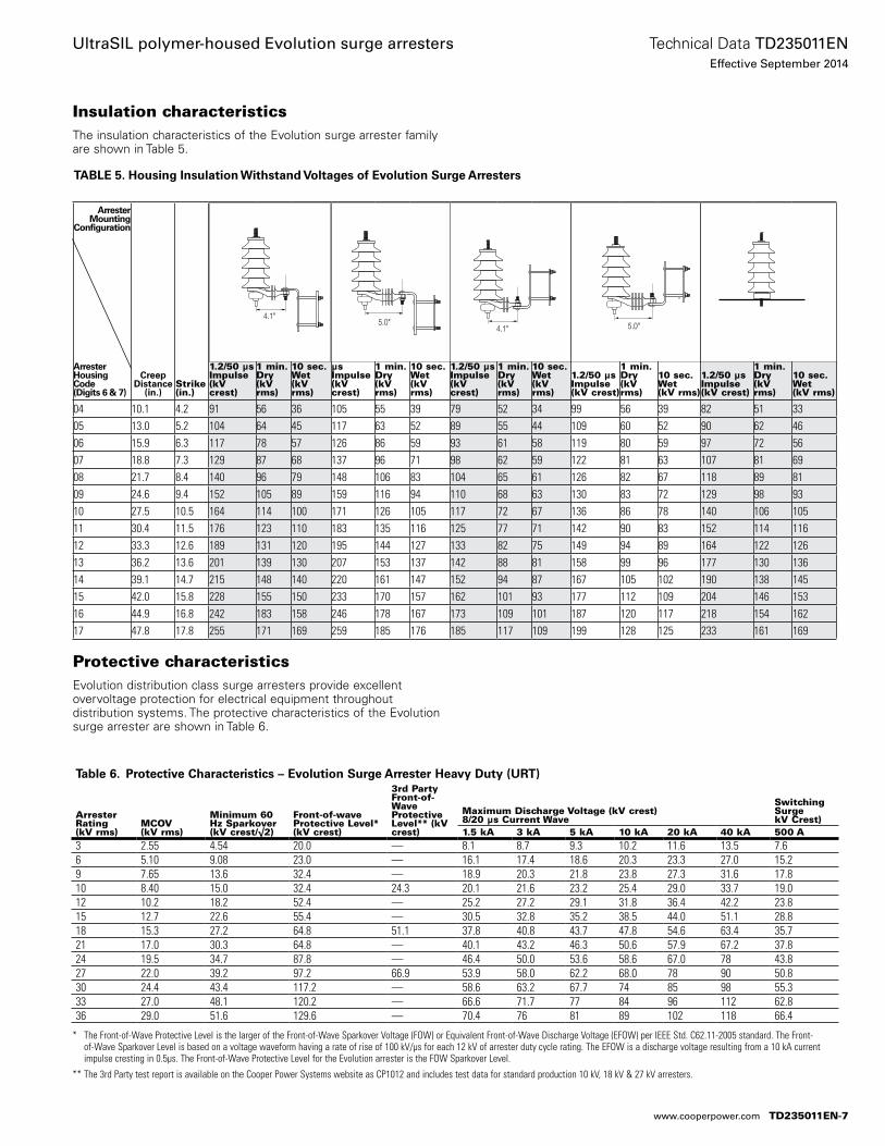
Insulation characteristicsThe insulation characteristics of the Evolution surge arrester family are shown in Table 5.
Protective characteristicsEvolution distribution class surge arresters provide excellent overvoltage protection for electrical equipment throughout distribution systems. The protective characteristics of the Evolution surge arrester are shown in Table 6.
TABLE 5. Housing Insulation Withstand Voltages of Evolution Surge Arresters
ArresterMounting
Configuration
ArresterHousingCode (Digits 6 & 7)
Creep Distance
(in.)Strike(in.)
1.2/50 µsImpulse(kV crest)
1 min. Dry(kV rms)
10 sec.Wet(kV rms)
1.2/50 µsImpulse(kV crest)
1 min. Dry(kV rms)
10 sec.Wet(kV rms)
1.2/50 µsImpulse(kV crest)
1 min. Dry(kV rms)
10 sec.Wet(kV rms)
1.2/50 µsImpulse(kV crest)
1 min. Dry(kV rms)
10 sec.Wet(kV rms)
1.2/50 µsImpulse(kV crest)
1 min. Dry(kV rms)
10 sec.Wet(kV rms)
04 10.1 4.2 91 56 36 105 55 39 79 52 34 99 56 39 82 51 3305 13.0 5.2 104 64 45 117 63 52 89 55 44 109 60 52 90 62 4606 15.9 6.3 117 78 57 126 86 59 93 61 58 119 80 59 97 72 5607 18.8 7.3 129 87 68 137 96 71 98 62 59 122 81 63 107 81 6908 21.7 8.4 140 96 79 148 106 83 104 65 61 126 82 67 118 89 8109 24.6 9.4 152 105 89 159 116 94 110 68 63 130 83 72 129 98 9310 27.5 10.5 164 114 100 171 126 105 117 72 67 136 86 78 140 106 10511 30.4 11.5 176 123 110 183 135 116 125 77 71 142 90 83 152 114 11612 33.3 12.6 189 131 120 195 144 127 133 82 75 149 94 89 164 122 12613 36.2 13.6 201 139 130 207 153 137 142 88 81 158 99 96 177 130 13614 39.1 14.7 215 148 140 220 161 147 152 94 87 167 105 102 190 138 14515 42.0 15.8 228 155 150 233 170 157 162 101 93 177 112 109 204 146 15316 44.9 16.8 242 183 158 246 178 167 173 109 101 187 120 117 218 154 16217 47.8 17.8 255 171 169 259 185 176 185 117 109 199 128 125 233 161 169
4.1"5.0"
4.1" 5.0"
* The Front-of-Wave Protective Level is the larger of the Front-of-Wave Sparkover Voltage (FOW) or Equivalent Front-of-Wave Discharge Voltage (EFOW) per IEEE Std. C62.11-2005 standard. The Front-of-Wave Sparkover Level is based on a voltage waveform having a rate of rise of 100 kV/µs for each 12 kV of arrester duty cycle rating. The EFOW is a discharge voltage resulting from a 10 kA current impulse cresting in 0.5µs. The Front-of-Wave Protective Level for the Evolution arrester is the FOW Sparkover Level.
** The 3rd Party test report is available on the Cooper Power Systems website as CP1012 and includes test data for standard production 10 kV, 18 kV & 27 kV arresters.
Table 6. Protective Characteristics – Evolution Surge Arrester Heavy Duty (URT)
Arrester Rating (kV rms)
MCOV (kV rms)
Minimum 60 Hz Sparkover (kV crest/ √2)
Front-of-wave Protective Level* (kV crest)
3rd Party Front-of-Wave Protective Level** (kV crest)
Maximum Discharge Voltage (kV crest)8/20 µs Current Wave
Switching Surge kV Crest)
1.5 kA 3 kA 5 kA 10 kA 20 kA 40 kA 500 A3 2.55 4.54 20.0 — 8.1 8.7 9.3 10.2 11.6 13.5 7.66 5.10 9.08 23.0 — 16.1 17.4 18.6 20.3 23.3 27.0 15.29 7.65 13.6 32.4 — 18.9 20.3 21.8 23.8 27.3 31.6 17.810 8.40 15.0 32.4 24.3 20.1 21.6 23.2 25.4 29.0 33.7 19.012 10.2 18.2 52.4 — 25.2 27.2 29.1 31.8 36.4 42.2 23.815 12.7 22.6 55.4 — 30.5 32.8 35.2 38.5 44.0 51.1 28.818 15.3 27.2 64.8 51.1 37.8 40.8 43.7 47.8 54.6 63.4 35.721 17.0 30.3 64.8 — 40.1 43.2 46.3 50.6 57.9 67.2 37.824 19.5 34.7 87.8 — 46.4 50.0 53.6 58.6 67.0 78 43.827 22.0 39.2 97.2 66.9 53.9 58.0 62.2 68.0 78 90 50.830 24.4 43.4 117.2 — 58.6 63.2 67.7 74 85 98 55.333 27.0 48.1 120.2 — 66.6 71.7 77 84 96 112 62.836 29.0 51.6 129.6 — 70.4 76 81 89 102 118 66.4
TD235011EN-7
Technical Data TD235011ENEffective September 2014
UltraSIL polymer-housed Evolution surge arresters
www.cooperpower.com
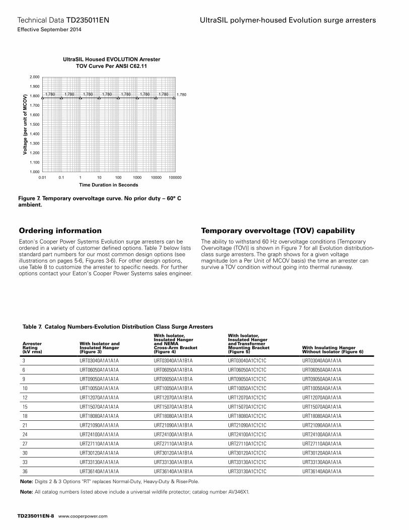
Ordering informationEaton's Cooper Power Systems Evolution surge arresters can be ordered in a variety of customer defined options. Table 7 below lists standard part numbers for our most common design options (see illustrations on pages 5-6, Figures 3-6). For other design options, use Table 8 to customize the arrester to specific needs. For further options contact your Eaton's Cooper Power Systems sales engineer.
Temporary overvoltage (TOV) capabilityThe ability to withstand 60 Hz overvoltage conditions [Temporary Overvoltage (TOV)] is shown in Figure 7 for all Evolution distribution-class surge arresters. The graph shows for a given voltage magnitude (on a Per Unit of MCOV basis) the time an arrester can survive a TOV condition without going into thermal runaway.
UltraSIL Housed EVOLUTION Arrester TOV Curve Per ANSI C62.11
1.7801.7801.7801.7801.7801.7801.7801.780
1.000
1.100
1.200
1.300
1.400
1.500
1.600
1.700
1.800
1.900
2.000
0.01 0.1 1 10 100 1000 10000 100000
Time Duration in Seconds
Volta
ge (p
er u
nit o
f MC
OV)
Table 7. Catalog Numbers-Evolution Distribution Class Surge Arresters
ArresterRating(kV rms)
With Isolator andInsulated Hanger(Figure 3)
With Isolator,Insulated Hangerand NEMACross-Arm Bracket(Figure 4)
With Isolator,Insulated Hangerand TransformerMounting Bracket(Figure 5)
With Insulating Hanger Without Isolator (Figure 6)
3 URT03040A1A1A1A URT03040A1A1B1A URT03040A1C1C1C URT03040A0A1A1A
6 URT06050A1A1A1A URT06050A1A1B1A URT06050A1C1C1C URT06050A0A1A1A
9 URT09050A1A1A1A URT09050A1A1B1A URT09050A1C1C1C URT09050A0A1A1A
10 URT10050A1A1A1A URT10050A1A1B1A URT10050A1C1C1C URT10050A0A1A1A
12 URT12070A1A1A1A URT12070A1A1B1A URT12070A1C1C1C URT12070A0A1A1A
15 URT15070A1A1A1A URT15070A1A1B1A URT15070A1C1C1C URT15070A0A1A1A
18 URT18080A1A1A1A URT18080A1A1B1A URT18080A1C1C1C URT18080A0A1A1A
21 URT21090A1A1A1A URT21090A1A1B1A URT21090A1C1C1C URT21090A0A1A1A
24 URT24100A1A1A1A URT24100A1A1B1A URT24100A1C1C1C URT24100A0A1A1A
27 URT27110A1A1A1A URT27110A1A1B1A URT27110A1C1C1C URT27110A0A1A1A
30 URT30120A1A1A1A URT30120A1A1B1A URT30120A1C1C1C URT30120A0A1A1A
33 URT33130A1A1A1A URT33130A1A1B1A URT33130A1C1C1C URT33130A0A1A1A
36 URT36140A1A1A1A URT36140A1A1B1A URT33130A1C1C1C URT36140A0A1A1A
ote:N Digits 2 & 3 Options "RT" replaces Normal-Duty, Heavy-Duty & Riser-Pole.
ote:N All catalog numbers listed above include a universal wildlife protector; catalog number AV346X1.
Figure 7. Temporary overvoltage curve. No prior duty – 60° C ambient.
TD235011EN-8
Technical Data TD235011ENEffective September 2014
UltraSIL polymer-housed Evolution surge arresters
www.cooperpower.com
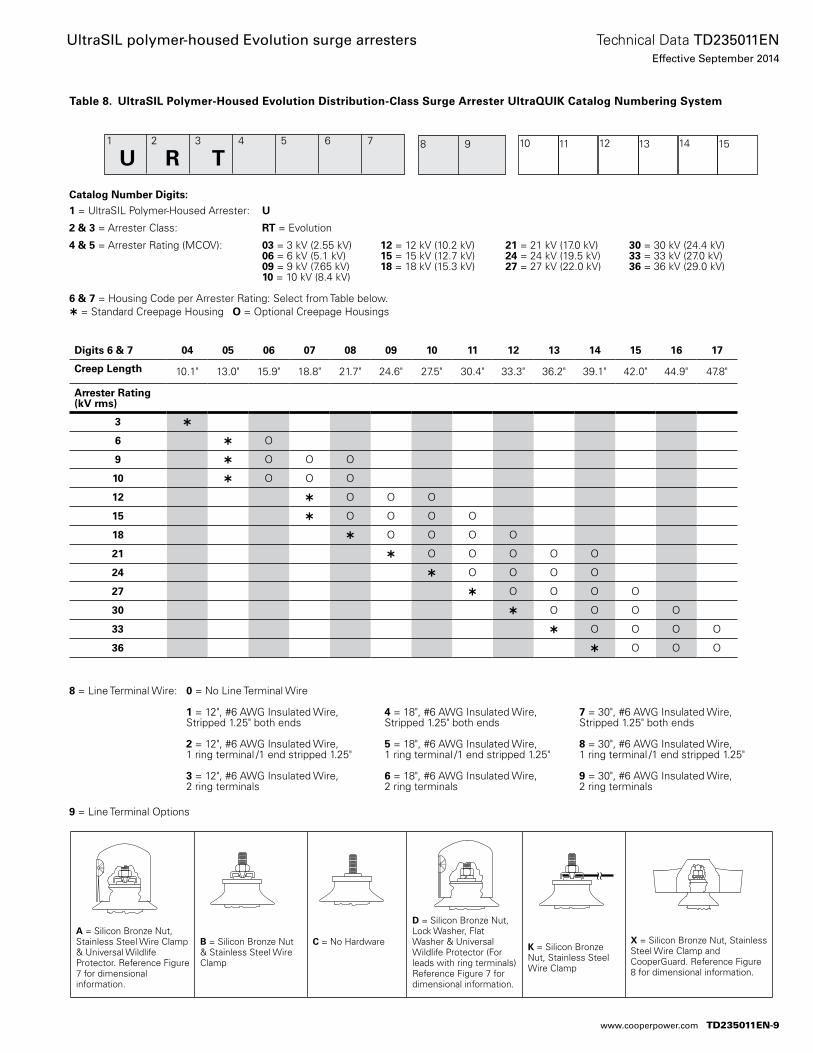
Table 8. UltraSIL Polymer-Housed Evolution Distribution-Class Surge Arrester UltraQUIK Catalog Numbering System
A = Silicon Bronze Nut, Stainless Steel Wire Clamp & Universal Wildlife Protector. Reference Figure 7 for dimensional information.
B = Silicon Bronze Nut & Stainless Steel Wire Clamp
C = No Hardware
D = Silicon Bronze Nut, Lock Washer, Flat Washer & Universal Wildlife Protector (For leads with ring terminals) Reference Figure 7 for dimensional information.
K = Silicon Bronze Nut, Stainless Steel Wire Clamp
X = Silicon Bronze Nut, Stainless Steel Wire Clamp and CooperGuard. Reference Figure 8 for dimensional information.
Catalog Number Digits:
1 = UltraSIL Polymer-Housed Arrester: U 2 & 3 = Arrester Class: RT = Evolution 4 & 5 = Arrester Rating (MCOV): 03 = 3 kV (2.55 kV) 12 = 12 kV (10.2 kV) 21 = 21 kV (17.0 kV) 30 = 30 kV (24.4 kV) 06 = 6 kV (5.1 kV) 15 = 15 kV (12.7 kV) 24 = 24 kV (19.5 kV) 33 = 33 kV (27.0 kV) 09 = 9 kV (7.65 kV) 18 = 18 kV (15.3 kV) 27 = 27 kV (22.0 kV) 36 = 36 kV (29.0 kV) 10 = 10 kV (8.4 kV)
6 & 7 = Housing Code per Arrester Rating: Select from Table below. = Standard Creepage Housing O = Optional Creepage Housings
8 = Line Terminal Wire: 0 = No Line Terminal Wire 1 = 12", #6 AWG Insulated Wire, 4 = 18", #6 AWG Insulated Wire, 7 = 30", #6 AWG Insulated Wire, Stripped 1.25" both ends Stripped 1.25" both ends Stripped 1.25" both ends
2 = 12", #6 AWG Insulated Wire, 5 = 18", #6 AWG Insulated Wire, 8 = 30", #6 AWG Insulated Wire, 1 ring terminal /1 end stripped 1.25" 1 ring terminal /1 end stripped 1.25" 1 ring terminal /1 end stripped 1.25"
3 = 12", #6 AWG Insulated Wire, 6 = 18", #6 AWG Insulated Wire, 9 = 30", #6 AWG Insulated Wire, 2 ring terminals 2 ring terminals 2 ring terminals
9 = Line Terminal Options
Digits 6 & 7 04 05 06 07 08 09 10 11 12 13 14 15 16 17
Creep Length 10.1" 13.0" 15.9" 18.8" 21.7" 24.6" 27.5" 30.4" 33.3" 36.2" 39.1" 42.0" 44.9" 47.8"
Arrester Rating (kV rms)
3
6 O
9 O O O
10 O O O
12 O O O
15 O O O O
18 O O O O
21 O O O O O
24 O O O O
27 O O O O
30 O O O O
33 O O O O
36 O O O
1 2 3 4 5 6 7
U R T 8 9 1110 1312 1514
TD235011EN-9
Technical Data TD235011ENEffective September 2014
UltraSIL polymer-housed Evolution surge arresters
www.cooperpower.com
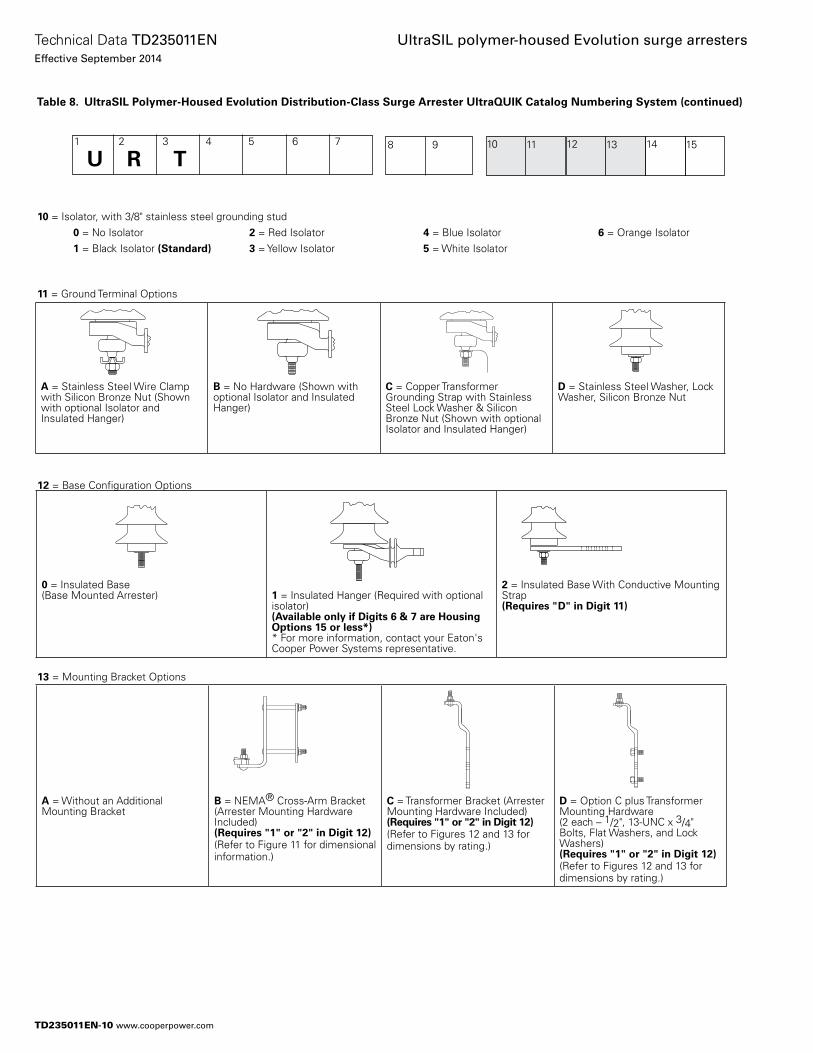
10 = Isolator, with 3/8" stainless steel grounding stud 0 = No Isolator 2 = Red Isolator 4 = Blue Isolator 6 = Orange Isolator 1 = Black Isolator (Standard) 3 = Yellow Isolator 5 = White Isolator
11 = Ground Terminal Options
12 = Base Configuration Options
13 = Mounting Bracket Options
A = Stainless Steel Wire Clamp with Silicon Bronze Nut (Shown with optional Isolator and Insulated Hanger)
B = No Hardware (Shown with optional Isolator and Insulated Hanger)
C = Copper Transformer Grounding Strap with Stainless Steel Lock Washer & Silicon Bronze Nut (Shown with optional Isolator and Insulated Hanger)
D = Stainless Steel Washer, Lock Washer, Silicon Bronze Nut
0 = Insulated Base (Base Mounted Arrester) 1 = Insulated Hanger (Required with optional
isolator)(Available only if Digits 6 & 7 are Housing Options 15 or less*)* For more information, contact your Eaton's Cooper Power Systems representative.
2 = Insulated Base With Conductive Mounting Strap (Requires "D" in Digit 11)
A = Without an Additional Mounting Bracket
B = NEMA® Cross-Arm Bracket (Arrester Mounting Hardware Included) (Requires "1" or "2" in Digit 12)(Refer to Figure 11 for dimensional information.)
C = Transformer Bracket (Arrester Mounting Hardware Included) (Requires "1" or "2" in Digit 12)(Refer to Figures 12 and 13 for dimensions by rating.)
D = Option C plus Transformer Mounting Hardware (2 each – 1/2", 13-UNC x 3/4" Bolts, Flat Washers, and Lock Washers) (Requires "1" or "2" in Digit 12)(Refer to Figures 12 and 13 for dimensions by rating.)
Table 8. UltraSIL Polymer-Housed Evolution Distribution-Class Surge Arrester UltraQUIK Catalog Numbering System (continued)
1 2 3 4 5 6 7
U R T 8 9 1110 1312 1514
TD235011EN-10
Technical Data TD235011ENEffective September 2014
UltraSIL polymer-housed Evolution surge arresters
www.cooperpower.com
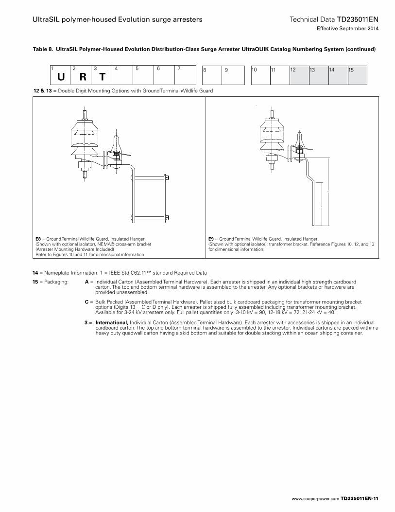
14 = Nameplate Information: 1 = IEEE Std C62.11™ standard Required Data
15 = Packaging: A = Individual Carton (Assembled Terminal Hardware). Each arrester is shipped in an individual high strength cardboard carton. The top and bottom terminal hardware is assembled to the arrester. Any optional brackets or hardware are provided unassembled.
C = Bulk Packed (Assembled Terminal Hardware). Pallet sized bulk cardboard packaging for transformer mounting bracket options (Digits 13 = C or D only). Each arrester is shipped fully assembled including transformer mounting bracket. Available for 3-24 kV arresters only. Full pallet quantities only: 3-10 kV = 90, 12-18 kV = 72, 21-24 kV = 40.
3 = International, Individual Carton (Assembled Terminal Hardware). Each arrester with accessories is shipped in an individual cardboard carton. The top and bottom terminal hardware is assembled to the arrester. Individual cartons are packed within a heavy duty quadwall carton having a skid bottom and suitable for double stacking within an ocean shipping container.
Table 8. UltraSIL Polymer-Housed Evolution Distribution-Class Surge Arrester UltraQUIK Catalog Numbering System (continued)
1 2 3 4 5 6 7
U R T 8 9 1110 1312 1514
12 & 13 = Double Digit Mounting Options with Ground Terminal Wildlife Guard
E8 = Ground Terminal Wildlife Guard, Insulated Hanger(Shown with optional isolator), NEMA® cross-arm bracket (Arrester Mounting Hardware Included)Refer to Figures 10 and 11 for dimensional information
E9 = Ground Terminal Wildlife Guard, Insulated Hanger (Shown with optional isolator), transformer bracket. Reference Figures 10, 12, and 13 for dimensional information.
TD235011EN-11
Technical Data TD235011ENEffective September 2014
UltraSIL polymer-housed Evolution surge arresters
www.cooperpower.com
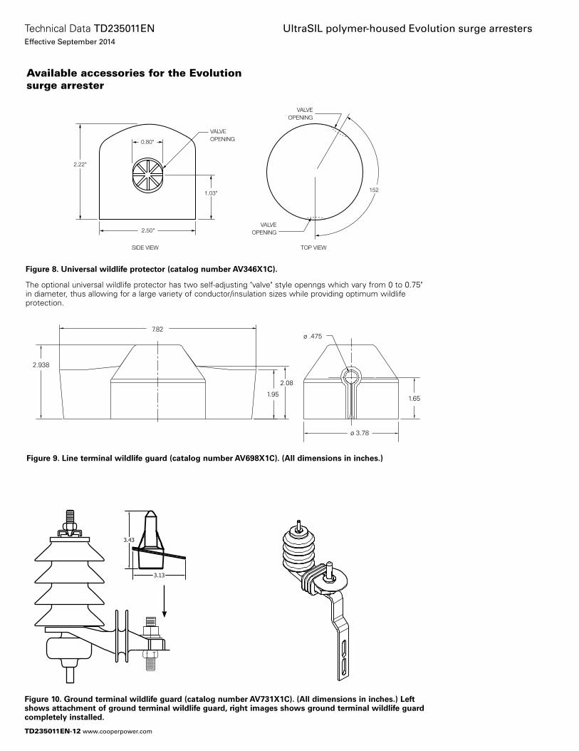
Available accessories for the Evolution surge arrester
Figure 8. Universal wildlife protector (catalog number AV346X1C).
The optional universal wildlife protector has two self-adjusting "valve" style openngs which vary from 0 to 0.75" in diameter, thus allowing for a large variety of conductor/insulation sizes while providing optimum wildlife protection.
0.80"
2.50"
1.03"
2.22"
VALVEOPENING
VALVEOPENING
VALVEOPENING
SIDE VIEW TOP VIEW
152
Figure 9. Line terminal wildlife guard (catalog number AV698X1C). (All dimensions in inches.)
7.82
2.938
2.08
1.951.65
ø .475
ø 3.78
Figure 10. Ground terminal wildlife guard (catalog number AV731X1C). (All dimensions in inches.) Left shows attachment of ground terminal wildlife guard, right images shows ground terminal wildlife guard completely installed.
TD235011EN-12
Technical Data TD235011ENEffective September 2014
UltraSIL polymer-housed Evolution surge arresters
www.cooperpower.com
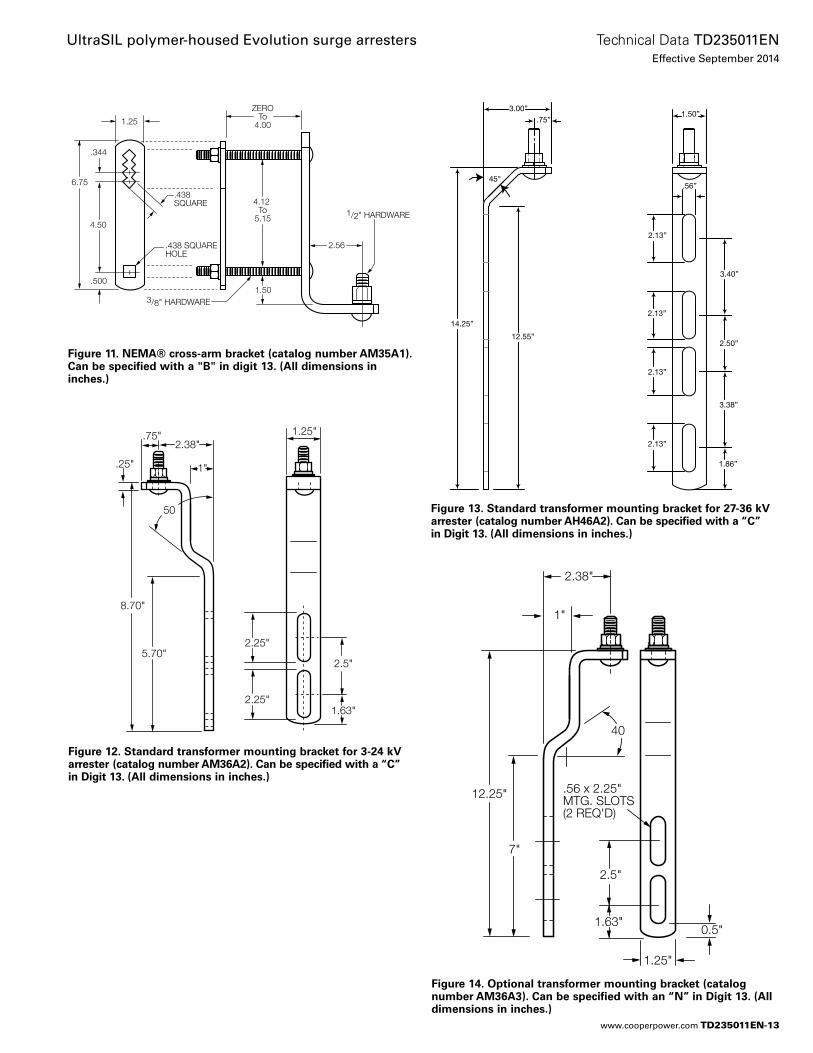
Figure 11. NEMA® cross-arm bracket (catalog number AM35A1). Can be specified with a "B" in digit 13. (All dimensions in inches.)
2.38"
.25"
.75"
1"
8.70"
5.70"
1.63"
2.25"
50
2.5"
2.25"
1.25"
Figure 12. Standard transformer mounting bracket for 3-24 kV arrester (catalog number AM36A2). Can be specified with a “C” in Digit 13. (All dimensions in inches.)
Figure 13. Standard transformer mounting bracket for 27-36 kV arrester (catalog number AH46A2). Can be specified with a “C” in Digit 13. (All dimensions in inches.)
3.00”.75”
45°
14.25”
12.55”
2.13”
2.13”
2.13”
2.13”
.56”
3.40”
2.50”
3.38”
1.86”
1.50”ZERO
To4.00
4.12 To
5.15
6.75
2.56
4.50
.344
1.25
.438SQUARE
.438 SQUAREHOLE
.5001.50
3/8" HARDWARE
1/2" HARDWARE
2.38"
1"
12.25"
7"
1.63"
2.5"
40
0.5"
.56 x 2.25"MTG. SLOTS(2 REQ'D)
1.25"
Figure 14. Optional transformer mounting bracket (catalog number AM36A3). Can be specified with an “N” in Digit 13. (All dimensions in inches.)
TD235011EN-13
Technical Data TD235011ENEffective September 2014
UltraSIL polymer-housed Evolution surge arresters
www.cooperpower.com
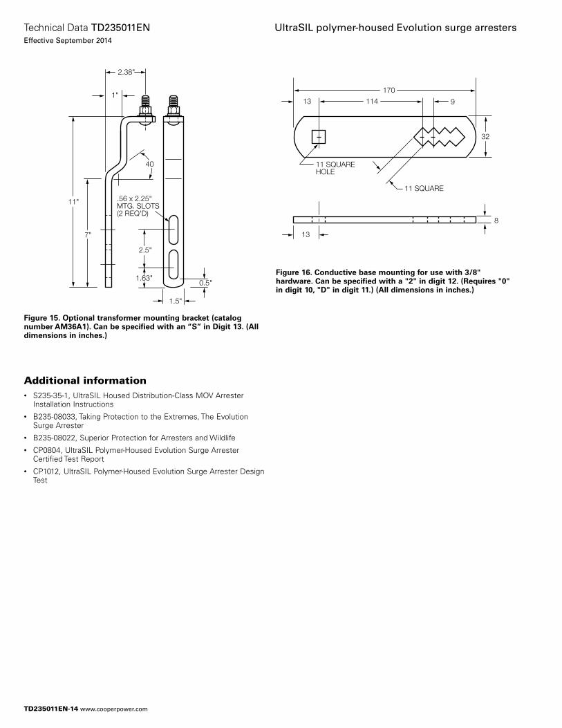
Figure 15. Optional transformer mounting bracket (catalog number AM36A1). Can be specified with an “S” in Digit 13. (All dimensions in inches.)
2.38"
1"
11"
7"
1.63"
2.5"
40
0.5"
.56 x 2.25"MTG. SLOTS(2 REQ'D)
1.5"
114
11 SQUARE
11 SQUAREHOLE
13
13
8
170
9
114
(2) 13 mm O
13
8
32
32
170
13
Figure 16. Conductive base mounting for use with 3/8" hardware. Can be specified with a "2" in digit 12. (Requires "0" in digit 10, "D" in digit 11.) (All dimensions in inches.)
Additional information• S235-35-1, UltraSIL Housed Distribution-Class MOV Arrester
Installation Instructions• B235-08033, Taking Protection to the Extremes, The Evolution
Surge Arrester• B235-08022, Superior Protection for Arresters and Wildlife• CP0804, UltraSIL Polymer-Housed Evolution Surge Arrester
Certified Test Report• CP1012, UltraSIL Polymer-Housed Evolution Surge Arrester Design
Test
TD235011EN-14
Technical Data TD235011ENEffective September 2014
UltraSIL polymer-housed Evolution surge arresters
www.cooperpower.com
TD235011EN-15
Technical Data TD235011ENEffective September 2014
UltraSIL polymer-housed Evolution surge arresters
www.cooperpower.com
Eaton, Cooper Power Systems, VariSTAR, UltraSIL, Evolution, and UltraQUIK are valuable trademarks of Eaton in the U.S. and other countries. You are not permitted to use the these trademarks without the prior written consent of Eaton.IEEE Std C62.11™-2005 and Std C62.22™ standards are trademarks of the Institute of Electrical and Electronics Engineers, Inc., (IEEE). This publication is not endorsed or approved by the IEEE.IEEE® is a registered trademark of the Institute of Electrical and Electronics Engineers, Inc.
UltraSIL polymer-housed Evolution surge arresters
Eaton1000 Eaton BoulevardCleveland, OH 44122United StatesEaton.com
Eaton’s Cooper Power Systems Business2300 Badger DriveWaukesha, WI 53188United StatesCooperpower.com
© 2014 EatonAll Rights ReservedPrinted in USAPublication No. TD235011EN
Technical Data TD235011ENEffective September 2014
For Eaton’s Cooper Power Systems Evolution surge arrester product information call 1-877-277-4636 or visit: www.cooperpower.com.
TD235011EN-16
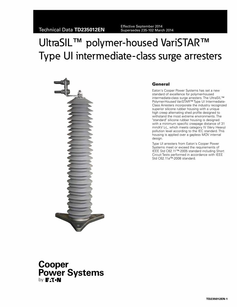
UltraSIL™ polymer-housed VariSTAR™ Type UI intermediate-class surge arresters
GeneralEaton's Cooper Power Systems has set a new standard of excellence for polymer-housed intermediate-class surge arresters. The UltraSIL™ Polymer-Housed VariSTAR™ Type UI Intermediate-Class Arresters incorporate the industry recognized superior silicone rubber housing with a unique high creep alternating shed profile designed to withstand the most extreme environments. The "standard" silicone rubber housing is designed with a minimum specific creepage distance of 31 mm/kV L-L, which meets category IV (Very Heavy) pollution level according to the IEC standard. This housing is applied over a gapless MOV internal design.
Type UI arresters from Eaton's Cooper Power Systems meet or exceed the requirements of IEEE Std C62.11™-2005 standard including Short Circuit Tests performed in accordance with IEEE Std C62.11a™-2008 standard.
TD235012EN-1
Technical Data TD235012ENEffective September 2014Supersedes 235-102 March 2014
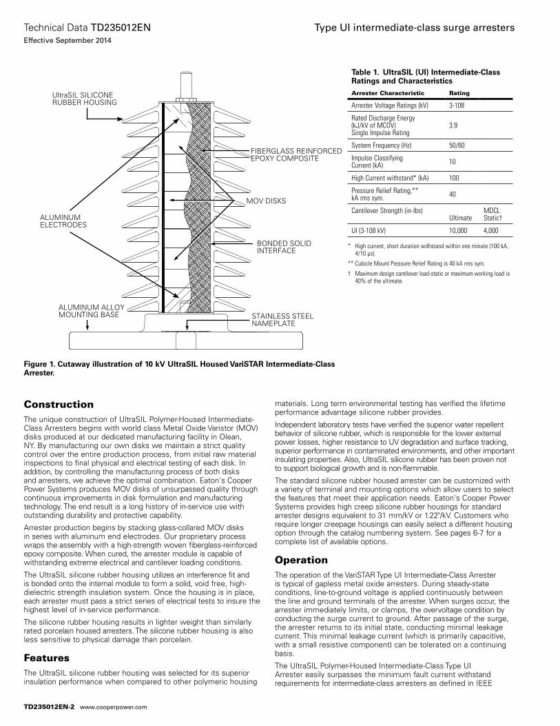
ConstructionThe unique construction of UltraSIL Polymer-Housed Intermediate-Class Arresters begins with world class Metal Oxide Varistor (MOV) disks produced at our dedicated manufacturing facility in Olean, NY. By manufacturing our own disks we maintain a strict quality control over the entire pro duction process, from initial raw material inspections to final physical and electrical testing of each disk. In addition, by controlling the manufacturing process of both disks and arresters, we achieve the optimal combination. Eaton's Cooper Power Systems produces MOV disks of unsurpassed quality through continuous improvements in disk formulation and manufacturing technology. The end result is a long history of in-service use with outstanding durability and protective capability.
Arrester production begins by stacking glass-collared MOV disks in series with aluminum end electrodes. Our proprietary process wraps the assembly with a high-strength woven fiberglass-reinforced epoxy composite. When cured, the arrester module is capable of withstanding extreme electrical and cantilever loading conditions.
The UltraSIL silicone rubber housing utilizes an inter ference fit and is bonded onto the internal module to form a solid, void free, high-dielectric strength insulation system. Once the housing is in place, each arrester must pass a strict series of electrical tests to insure the highest level of in-service performance.
The silicone rubber housing results in lighter weight than similarly rated porcelain housed arresters. The silicone rubber housing is also less sensitive to physical damage than porcelain.
FeaturesThe UltraSIL silicone rubber housing was selected for its superior insula tion performance when compared to other polymeric housing
materials. Long term environmental testing has verified the lifetime performance advantage silicone rubber provides.
Independent laboratory tests have verified the superior water repellent behavior of silicone rubber, which is responsible for the lower external power losses, higher resistance to UV degradation and surface tracking, superior performance in contaminated environments, and other important insulating properties. Also, UltraSIL silicone rubber has been proven not to support biological growth and is non-flammable.
The standard silicone rubber housed arrester can be customized with a variety of terminal and mounting options which allow users to select the features that meet their application needs. Eaton's Cooper Power Systems provides high creep silicone rubber housings for standard arrester designs equivalent to 31 mm/kV or 1.22"/kV. Customers who require longer creepage housings can easily select a different housing option through the catalog numbering system. See pages 6-7 for a complete list of available options.
OperationThe operation of the VariSTAR Type UI Intermediate-Class Arrester is typical of gapless metal oxide arresters. During steady-state conditions, line-to-ground voltage is applied con tinuously between the line and ground terminals of the arrester. When surges occur, the arrester immediately limits, or clamps, the overvoltage condition by conducting the surge current to ground. After passage of the surge, the arrester returns to its initial state, conducting minimal leakage current. This minimal leakage current (which is primarily capacitive, with a small resistive component) can be tolerated on a continuing basis.
The UltraSIL Polymer-Housed Intermediate-Class Type UI Arrester easily surpasses the minimum fault current withstand requirements for intermediate-class arresters as defined in IEEE
Figure 1. Cutaway illustration of 10 kV UltraSIL Housed VariSTAR Intermediate-Class Arrester.
UltraSIL SILICONE RUBBER HOUSING
FIBERGLASS REINFORCED EPOXY COMPOSITE
BONDED SOLID INTERFACE
STAINLESS STEEL NAMEPLATE
MOV DISKS
ALUMINUM ELECTRODES
ALUMINUM ALLOY MOUNTING BASE
Table 1. UltraSIL (UI) Intermediate-Class Ratings and Characteristics
Arrester Characteristic Rating
Arrester Voltage Ratings (kV) 3-108
Rated Discharge Energy(kJ/kV of MCOV)Single Impulse Rating
3.9
System Frequency (Hz) 50/60
Impulse Classifying Current (kA) 10
High Current withstand* (kA) 100
Pressure Relief Rating,**kA rms sym. 40
Cantilever Strength (in-Ibs)Ultimate
MDCLStatic†
UI (3-108 kV) 10,000 4,000
* High current, short duration withstand within one minute (100 kA, 4/10 µs).
** Cubicle Mount Pressure Relief Rating is 40 kA rms sym.
† Maximum design cantilever load-static or maximum working load is 40% of the ultimate.
TD235012EN-2
Technical Data TD235012ENEffective September 2014
Type UI intermediate-class surge arresters
www.cooperpower.com
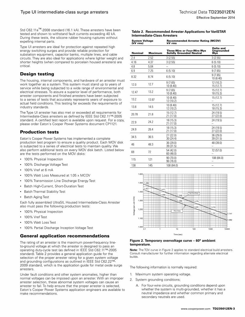
Std C62.11a™-2008 standard (16.1 kA). These arresters have been tested and shown to withstand fault currents exceeding 40 kA. During these tests, the silicone rubber housing ruptures without expelling internal parts.
Type UI arresters are ideal for protection against repeated high energy switching surges and provide reliable protection for substation equipment, capacitor banks, multiple lines, and cable circuits. They are also ideal for applications where lighter weight and shorter heights (when compared to porcelain housed arresters) are critical.
Design testingThe housing, internal components, and hardware of an arrester must work together as a system. This system must stand up to years of service while being subjected to a wide range of environmental and electrical stresses. To assure a superior level of performance, both arrester components and finished arresters have been subjected to a series of tests that accurately represents years of exposure to actual field conditions. This testing far exceeds the requirements of industry standards.
The Type UI arrester has also met or exceeded all requirements for Intermediate-Class arresters as defined by IEEE Std C62.11™-2005 standard. A certified test report is available upon request. For a copy, please order Eaton's Cooper Power Systems document CP1121.
Production testsEaton's Cooper Power Systems has implemented a complete production test program to ensure a quality product. Each MOV disk is subjected to a series of electrical tests to maintain quality. We also perform additional tests on every MOV disk batch. Listed below are the tests performed on the MOV disks:• 100% Physical Inspection• 100% Discharge Voltage Test• 100% Vref at 6 mA• 100% Watt Loss Measured at 1.05 x MCOV• 100% Transmission Line Discharge Energy Test• Batch High-Current, Short-Duration Test• Batch Thermal Stability Test• Batch Aging Test
Each fully assembled UltraSIL Housed Intermediate-Class Arrester also must pass the following production tests:• 100% Physical Inspection• 100% Vref Test• 100% Watt Loss Test• 100% Partial Discharge Inception Voltage Test
General application recommendationsThe rating of an arrester is the maximum power-frequency line-to-ground voltage at which the arrester is designed to pass an operating duty-cycle test (as defined in IEEE Std C62.11™-2005 standard). Table 2 provides a general application guide for the selection of the proper arrester rating for a given system voltage and grounding configurations as outlined in IEEE Std C62.22™-2009 standard, which is the application guide for metal oxide surge arresters.
Under fault conditions and other system anomalies, higher than normal voltages can be imposed upon an arrester. With an improper arrester selection, these abnormal system voltages can cause an arrester to fail. To help ensure that the proper arrester is selected, Eaton's Cooper Power Systems application engineers are available to make recommendations.
The following information is normally required:
1. Maximum system operating voltage.
2. System grounding conditions;
A. For four-wire circuits, grounding conditions depend upon whether the system is multi-grounded, whether it has a neutral impedance and whether common primary and secondary neutrals are used.
Figure 2. Temporary overvoltage curve – 60° ambient temperature.
Note: The TOV curve in Figure 2 applies to standard electrical build arresters. Consult manufacturer for further information regarding alternate electrical builds.
Table 2. Recommended Arrester Applications for VariSTAR Intermediate-Class Arresters
System Voltage (kV rms)
Recommended Arrester Rating (MCOV)kV rms
Nominal MaximumThree-Wire or Four-Wire Wye Solidly Grounded Neutral
Delta and UngroundedWye
2.4 2.52 3 (2.55) 3 (2.55)4.16 4.37 3 (2.55) 6 (5.10)4.8 5.04 – 6 (5.10)6.9 7.25 6 (5.10) 9 (7.65)
8.32 8.74 6 (5.10) 9 (7.65)10 (8.40)
12.0 12.7 9 (7.65)10 (8.40)
12 (10.2)15 (12.7)
12.47 13.2 9 (7.65)10 (8.40)
15 (12.7)18 (15.3)
13.2 13.9710 (8.40)12 (10.2)
15 (12.7)–
13.8 14.5 10 (8.40)12 (10.2)
15 (12.7)18 (15.3)
20.78 21.8 15 (12.7)21 (17.0)
24 (19.5)27 (22.0)
22.9 24.2 18 (15.3)21 (17.0)
24 (19.5)–
24.9 26.4 18 (15.3)21 (17.0)
24 (19.5)27 (22.0)
34.5 36.5 27 (22.0)30 (24.4)
36 (29.0)39 (31.5)
46 48.3 36 (29.0)39 (31.5)
48 (39.0)–
69 72 54 (42.0)60 (48.0)
72 (57.0)–
115 121 90 (70.0)96 (76.0)
108 (84.0)–
138 145 108 (84.0) –
1.600
1.500
1.400
1.300
1.200
1.100
1.000
1.486
1.417
1.348
1.279
1.210
1.141
1.427
1.358
1.289
1.220
1.151
1.082
0.1 1 10 100 1000 10000
Time (sec)
Volta
ge (p
er u
nit C
OV
)
No Prior Duty
Prior Duty
TD235012EN-3
Technical Data TD235012ENEffective September 2014
Type UI intermediate-class surge arresters
www.cooperpower.com
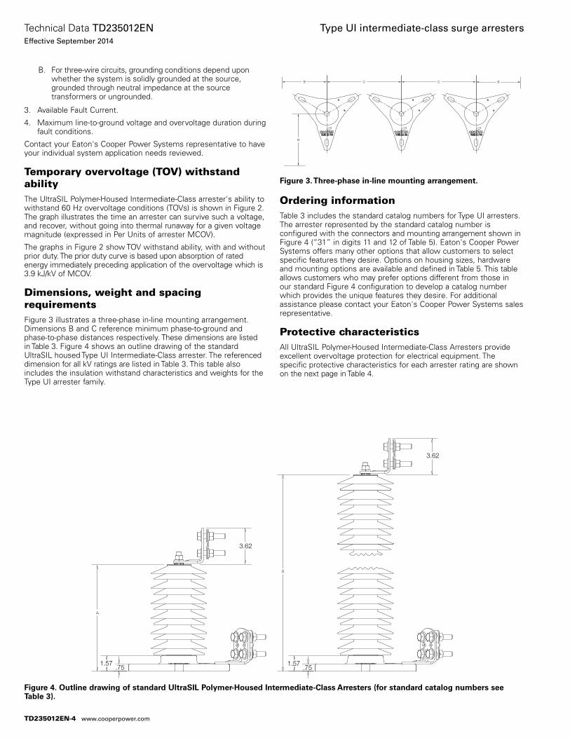
B. For three-wire circuits, grounding conditions depend upon whether the system is solidly grounded at the source, grounded through neutral impedance at the source transformers or ungrounded.
3. Available Fault Current.
4. Maximum line-to-ground voltage and overvoltage duration during fault conditions.
Contact your Eaton's Cooper Power Systems representative to have your individual system application needs reviewed.
Temporary overvoltage (TOV) withstand abilityThe UltraSIL Polymer-Housed Intermediate-Class arrester's ability to withstand 60 Hz overvoltage conditions (TOVs) is shown in Figure 2. The graph illustrates the time an arrester can survive such a voltage, and recover, without going into thermal runaway for a given voltage magnitude (expressed in Per Units of arrester MCOV).
The graphs in Figure 2 show TOV withstand ability, with and without prior duty. The prior duty curve is based upon absorption of rated energy immediately preceding application of the overvoltage which is 3.9 kJ/kV of MCOV.
Dimensions, weight and spacing requirementsFigure 3 illustrates a three-phase in-line mounting arrangement. Dimen sions B and C reference mini mum phase-to-ground and phase-to-phase distances respectively. These dimensions are listed in Table 3. Figure 4 shows an outline drawing of the standard UltraSIL housed Type UI Intermediate-Class arrester. The referenced di mension for all kV ratings are listed in Table 3. This table also includes the insulation withstand characteristics and weights for the Type UI arrester family.
Ordering informationTable 3 includes the standard catalog numbers for Type UI arresters. The arrester represented by the standard catalog number is configured with the connectors and mounting arrangement shown in Figure 4 (“31” in digits 11 and 12 of Table 5). Eaton's Cooper Power Systems offers many other options that allow customers to select specific features they desire. Options on housing sizes, hardware and mounting options are available and defined in Table 5. This table allows customers who may prefer options different from those in our standard Figure 4 configuration to develop a catalog number which provides the unique features they desire. For additional assistance please contact your Eaton's Cooper Power Systems sales representative.
Protective characteristicsAll UltraSIL Polymer-Housed Intermediate-Class Arresters provide excellent overvoltage protection for electrical equipment. The specific protective characteristics for each arrester rating are shown on the next page in Table 4.
Figure 3. Three-phase in-line mounting arrangement.
B
B
BCC
Figure 4. Outline drawing of standard UltraSIL Polymer-Housed Intermediate-Class Arresters (for standard catalog numbers see Table 3).
3.62
3.62
1.57.75
1.57.75
TD235012EN-4
Technical Data TD235012ENEffective September 2014
Type UI intermediate-class surge arresters
www.cooperpower.com
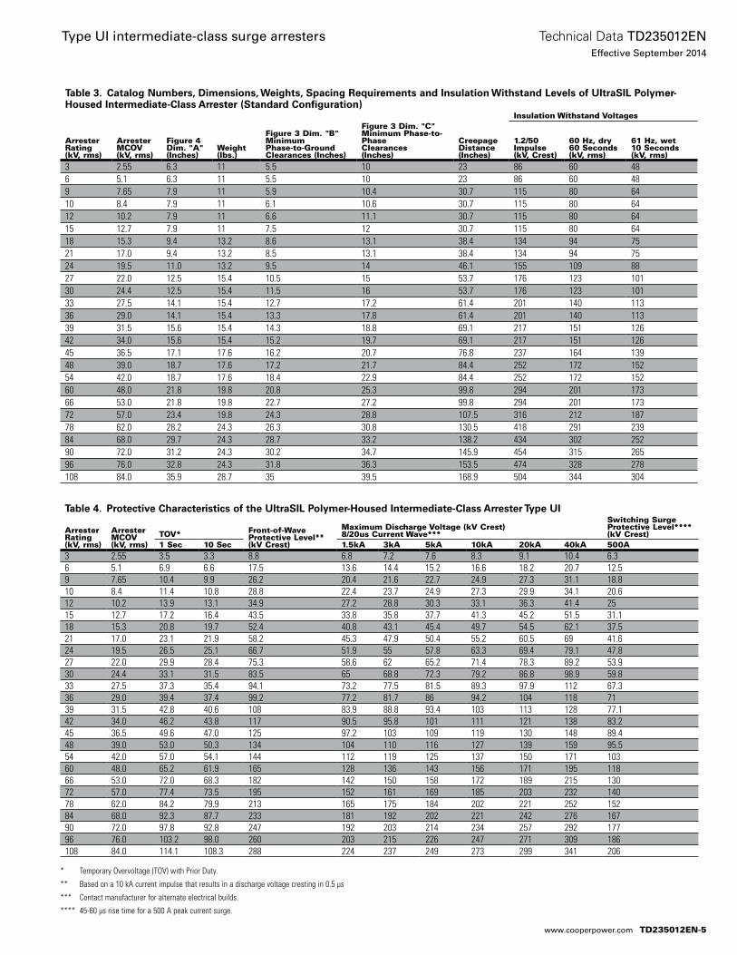
* Temporary Overvoltage (TOV) with Prior Duty.
** Based on a 10 kA current impulse that results in a discharge voltage cresting in 0.5 µs
*** Contact manufacturer for alternate electrical builds.
**** 45-60 µs rise time for a 500 A peak current surge.
Table 4. Protective Characteristics of the UltraSIL Polymer-Housed Intermediate-Class Arrester Type UI
Arrester Rating (kV, rms)
Arrester MCOV (kV, rms)
TOV* Front-of-Wave Protective Level** (kV Crest)
Maximum Discharge Voltage (kV Crest) 8/20us Current Wave***
Switching Surge Protective Level**** (kV Crest)
1 Sec 10 Sec 1.5kA 3kA 5kA 10kA 20kA 40kA 500A3 2.55 3.5 3.3 8.8 6.8 7.2 7.6 8.3 9.1 10.4 6.36 5.1 6.9 6.6 17.5 13.6 14.4 15.2 16.6 18.2 20.7 12.59 7.65 10.4 9.9 26.2 20.4 21.6 22.7 24.9 27.3 31.1 18.810 8.4 11.4 10.8 28.8 22.4 23.7 24.9 27.3 29.9 34.1 20.612 10.2 13.9 13.1 34.9 27.2 28.8 30.3 33.1 36.3 41.4 2515 12.7 17.2 16.4 43.5 33.8 35.8 37.7 41.3 45.2 51.5 31.118 15.3 20.8 19.7 52.4 40.8 43.1 45.4 49.7 54.5 62.1 37.521 17.0 23.1 21.9 58.2 45.3 47.9 50.4 55.2 60.5 69 41.624 19.5 26.5 25.1 66.7 51.9 55 57.8 63.3 69.4 79.1 47.827 22.0 29.9 28.4 75.3 58.6 62 65.2 71.4 78.3 89.2 53.930 24.4 33.1 31.5 83.5 65 68.8 72.3 79.2 86.8 98.9 59.833 27.5 37.3 35.4 94.1 73.2 77.5 81.5 89.3 97.9 112 67.336 29.0 39.4 37.4 99.2 77.2 81.7 86 94.2 104 118 7139 31.5 42.8 40.6 108 83.9 88.8 93.4 103 113 128 77.142 34.0 46.2 43.8 117 90.5 95.8 101 111 121 138 83.245 36.5 49.6 47.0 125 97.2 103 109 119 130 148 89.448 39.0 53.0 50.3 134 104 110 116 127 139 159 95.554 42.0 57.0 54.1 144 112 119 125 137 150 171 10360 48.0 65.2 61.9 165 128 136 143 156 171 195 11866 53.0 72.0 68.3 182 142 150 158 172 189 215 13072 57.0 77.4 73.5 195 152 161 169 185 203 232 14078 62.0 84.2 79.9 213 165 175 184 202 221 252 15284 68.0 92.3 87.7 233 181 192 202 221 242 276 16790 72.0 97.8 92.8 247 192 203 214 234 257 292 17796 76.0 103.2 98.0 260 203 215 226 247 271 309 186108 84.0 114.1 108.3 288 224 237 249 273 299 341 206
Table 3. Catalog Numbers, Dimensions, Weights, Spacing Requirements and Insulation Withstand Levels of UltraSIL Polymer-Housed Intermediate-Class Arrester (Standard Configuration)
Arrester Rating (kV, rms)
Arrester MCOV (kV, rms)
Figure 4 Dim. "A" (Inches)
Weight (lbs.)
Figure 3 Dim. "B" Minimum Phase-to-Ground Clearances (Inches)
Figure 3 Dim. "C" Minimum Phase-to-Phase Clearances (Inches)
Creepage Distance (Inches)
Insulation Withstand Voltages
1.2/50 Impulse (kV, Crest)
60 Hz, dry 60 Seconds (kV, rms)
61 Hz, wet 10 Seconds (kV, rms)
3 2.55 6.3 11 5.5 10 23 86 60 486 5.1 6.3 11 5.5 10 23 86 60 489 7.65 7.9 11 5.9 10.4 30.7 115 80 6410 8.4 7.9 11 6.1 10.6 30.7 115 80 6412 10.2 7.9 11 6.6 11.1 30.7 115 80 6415 12.7 7.9 11 7.5 12 30.7 115 80 6418 15.3 9.4 13.2 8.6 13.1 38.4 134 94 7521 17.0 9.4 13.2 8.5 13.1 38.4 134 94 7524 19.5 11.0 13.2 9.5 14 46.1 155 109 8827 22.0 12.5 15.4 10.5 15 53.7 176 123 10130 24.4 12.5 15.4 11.5 16 53.7 176 123 10133 27.5 14.1 15.4 12.7 17.2 61.4 201 140 11336 29.0 14.1 15.4 13.3 17.8 61.4 201 140 11339 31.5 15.6 15.4 14.3 18.8 69.1 217 151 12642 34.0 15.6 15.4 15.2 19.7 69.1 217 151 12645 36.5 17.1 17.6 16.2 20.7 76.8 237 164 13948 39.0 18.7 17.6 17.2 21.7 84.4 252 172 15254 42.0 18.7 17.6 18.4 22.9 84.4 252 172 15260 48.0 21.8 19.8 20.8 25.3 99.8 294 201 17366 53.0 21.8 19.8 22.7 27.2 99.8 294 201 17372 57.0 23.4 19.8 24.3 28.8 107.5 316 212 18778 62.0 28.2 24.3 26.3 30.8 130.5 418 291 23984 68.0 29.7 24.3 28.7 33.2 138.2 434 302 25290 72.0 31.2 24.3 30.2 34.7 145.9 454 315 26596 76.0 32.8 24.3 31.8 36.3 153.5 474 328 278108 84.0 35.9 28.7 35 39.5 168.9 504 344 304
TD235012EN-5
Technical Data TD235012ENEffective September 2014
Type UI intermediate-class surge arresters
www.cooperpower.com
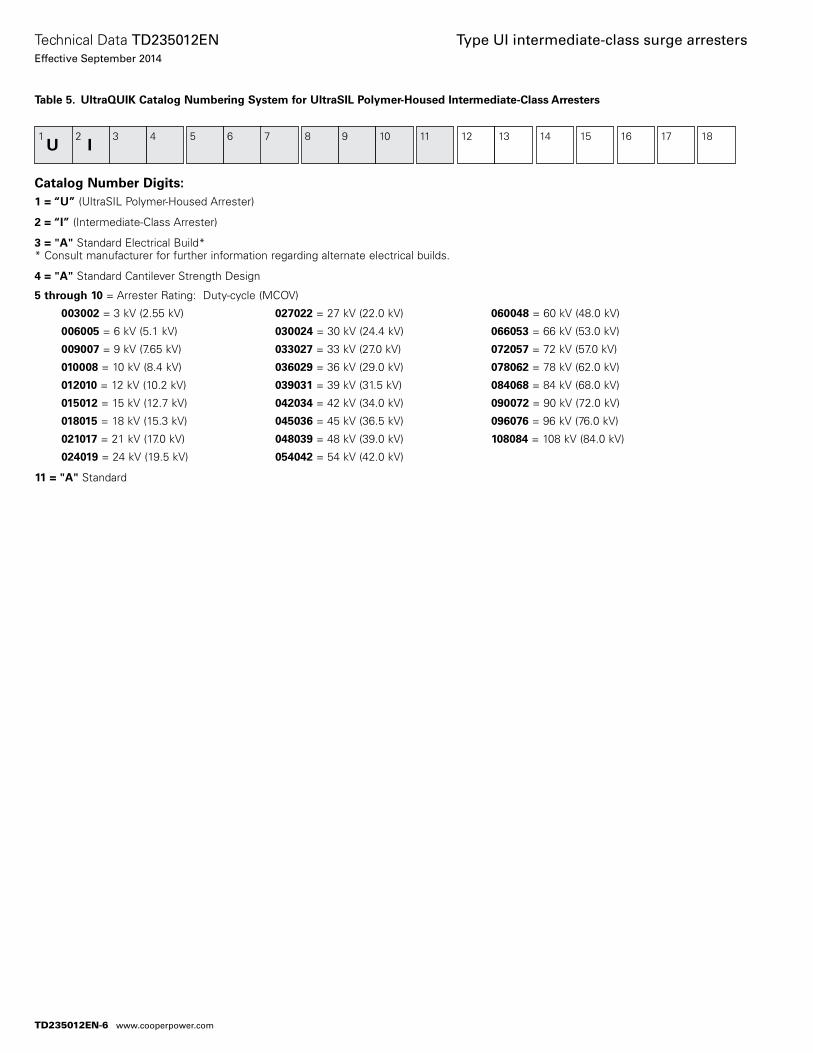
Table 5. UltraQUIK Catalog Numbering System for UltraSIL Polymer-Housed Intermediate-Class Arresters
Catalog Number Digits:1 = “U” (UltraSIL Polymer-Housed Arrester)
2 = “I” (Intermediate-Class Arrester)
3 = "A" Standard Electrical Build** Consult manufacturer for further information regarding alternate electrical builds.
4 = "A" Standard Cantilever Strength Design
5 through 10 = Arrester Rating: Duty-cycle (MCOV)
003002 = 3 kV (2.55 kV) 027022 = 27 kV (22.0 kV) 060048 = 60 kV (48.0 kV)
006005 = 6 kV (5.1 kV) 030024 = 30 kV (24.4 kV) 066053 = 66 kV (53.0 kV)
009007 = 9 kV (7.65 kV) 033027 = 33 kV (27.0 kV) 072057 = 72 kV (57.0 kV)
010008 = 10 kV (8.4 kV) 036029 = 36 kV (29.0 kV) 078062 = 78 kV (62.0 kV)
012010 = 12 kV (10.2 kV) 039031 = 39 kV (31.5 kV) 084068 = 84 kV (68.0 kV)
015012 = 15 kV (12.7 kV) 042034 = 42 kV (34.0 kV) 090072 = 90 kV (72.0 kV)
018015 = 18 kV (15.3 kV) 045036 = 45 kV (36.5 kV) 096076 = 96 kV (76.0 kV)
021017 = 21 kV (17.0 kV) 048039 = 48 kV (39.0 kV) 108084 = 108 kV (84.0 kV)
024019 = 24 kV (19.5 kV) 054042 = 54 kV (42.0 kV)
11 = "A" Standard
1U
2I
3
4 5 6
7 8
9
10
11 12 13 14 15 16 17 18
TD235012EN-6
Technical Data TD235012ENEffective September 2014
Type UI intermediate-class surge arresters
www.cooperpower.com
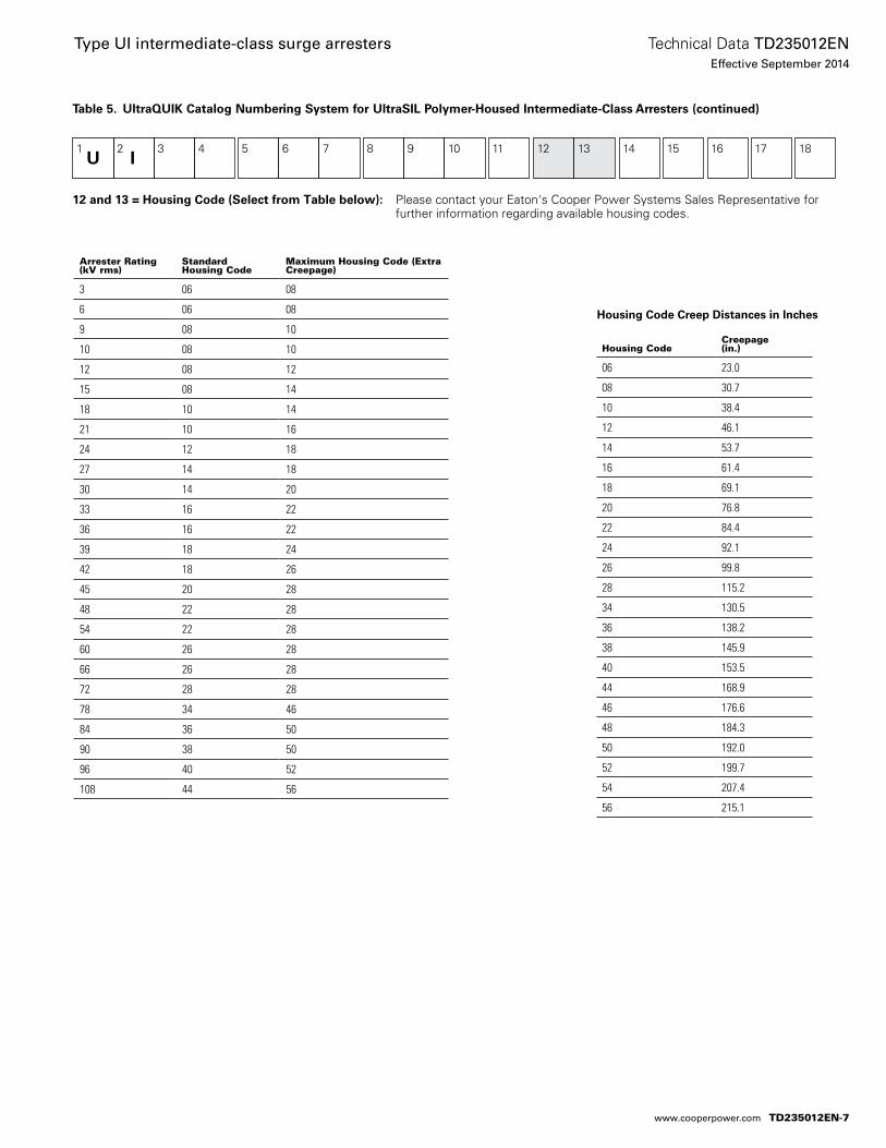
Table 5. UltraQUIK Catalog Numbering System for UltraSIL Polymer-Housed Intermediate-Class Arresters (continued)
1U
2I
3
4
5
6
7
8
9 10
11 12
13
14
15
16
17 18
Arrester Rating (kV rms)
Standard Housing Code
Maximum Housing Code (Extra Creepage)
3 06 08
6 06 08
9 08 10
10 08 10
12 08 12
15 08 14
18 10 14
21 10 16
24 12 18
27 14 18
30 14 20
33 16 22
36 16 22
39 18 24
42 18 26
45 20 28
48 22 28
54 22 28
60 26 28
66 26 28
72 28 28
78 34 46
84 36 50
90 38 50
96 40 52
108 44 56
Housing CodeCreepage (in.)
06 23.0
08 30.7
10 38.4
12 46.1
14 53.7
16 61.4
18 69.1
20 76.8
22 84.4
24 92.1
26 99.8
28 115.2
34 130.5
36 138.2
38 145.9
40 153.5
44 168.9
46 176.6
48 184.3
50 192.0
52 199.7
54 207.4
56 215.1
12 and 13 = Housing Code (Select from Table below): Please contact your Eaton's Cooper Power Systems Sales Representative for further information regarding available housing codes.
Housing Code Creep Distances in Inches
TD235012EN-7
Technical Data TD235012ENEffective September 2014
Type UI intermediate-class surge arresters
www.cooperpower.com
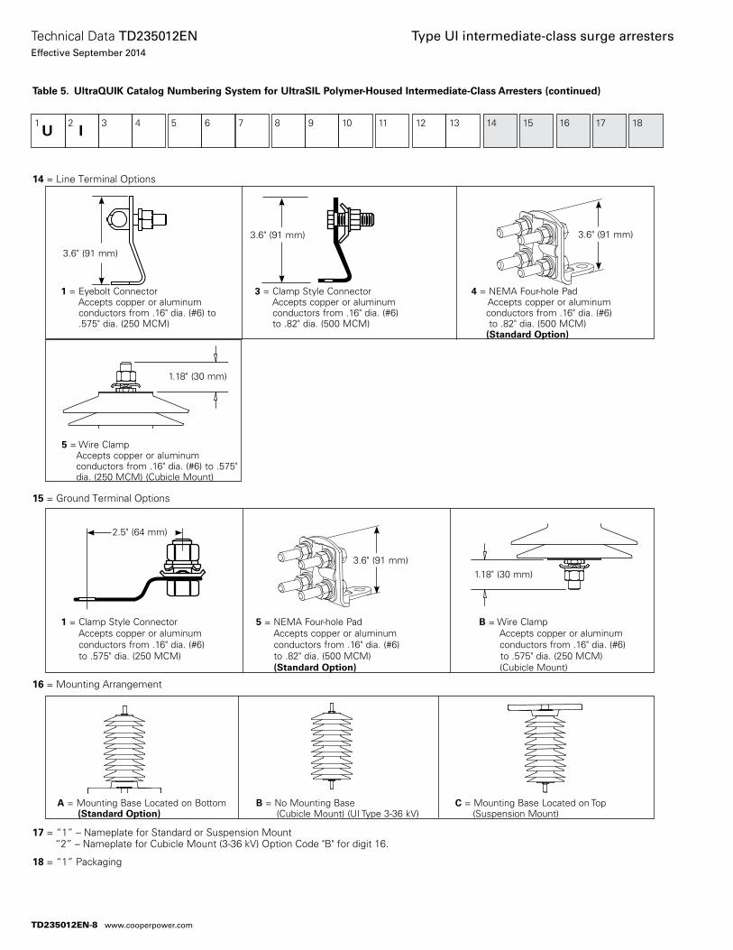
Table 5. UltraQUIK Catalog Numbering System for UltraSIL Polymer-Housed Intermediate-Class Arresters (continued)
14 = Line Terminal Options
15 = Ground Terminal Options
16 = Mounting Arrangement
17 = “1” – Nameplate for Standard or Suspension Mount “2” – Nameplate for Cubicle Mount (3-36 kV) Option Code "B" for digit 16.
18 = “1” Packaging
1 = Eyebolt Connector 3 = Clamp Style Connector 4 = NEMA Four-hole Pad Accepts copper or aluminum Accepts copper or aluminum Accepts copper or aluminum conductors from .16" dia. (#6) to conductors from .16" dia. (#6) conductors from .16" dia. (#6) .575" dia. (250 MCM) to .82" dia. (500 MCM) to .82" dia. (500 MCM) (Standard Option)
1 = Clamp Style Connector 5 = NEMA Four-hole Pad B = Wire Clamp Accepts copper or aluminum Accepts copper or aluminum Accepts copper or aluminum conductors from .16" dia. (#6) conductors from .16" dia. (#6) conductors from .16" dia. (#6) to .575" dia. (250 MCM) to .82" dia. (500 MCM) to .575" dia. (250 MCM) (Standard Option) (Cubicle Mount)
A = Mounting Base Located on Bottom B = No Mounting Base C = Mounting Base Located on Top (Standard Option) (Cubicle Mount) (UI Type 3-36 kV) (Suspension Mount)
1U
2I
3
4
5
6
7
8
9
10
11
12
13 14
15 16
17 18
5 = Wire Clamp Accepts copper or aluminum conductors from .16" dia. (#6) to .575" dia. (250 MCM) (Cubicle Mount)
1.18" (30 mm)
1.18" (30 mm)
3.6" (91 mm) 3.6" (91 mm)
3.6" (91 mm)
2.5" (64 mm)
3.6" (91 mm)
TD235012EN-8
Technical Data TD235012ENEffective September 2014
Type UI intermediate-class surge arresters
www.cooperpower.com
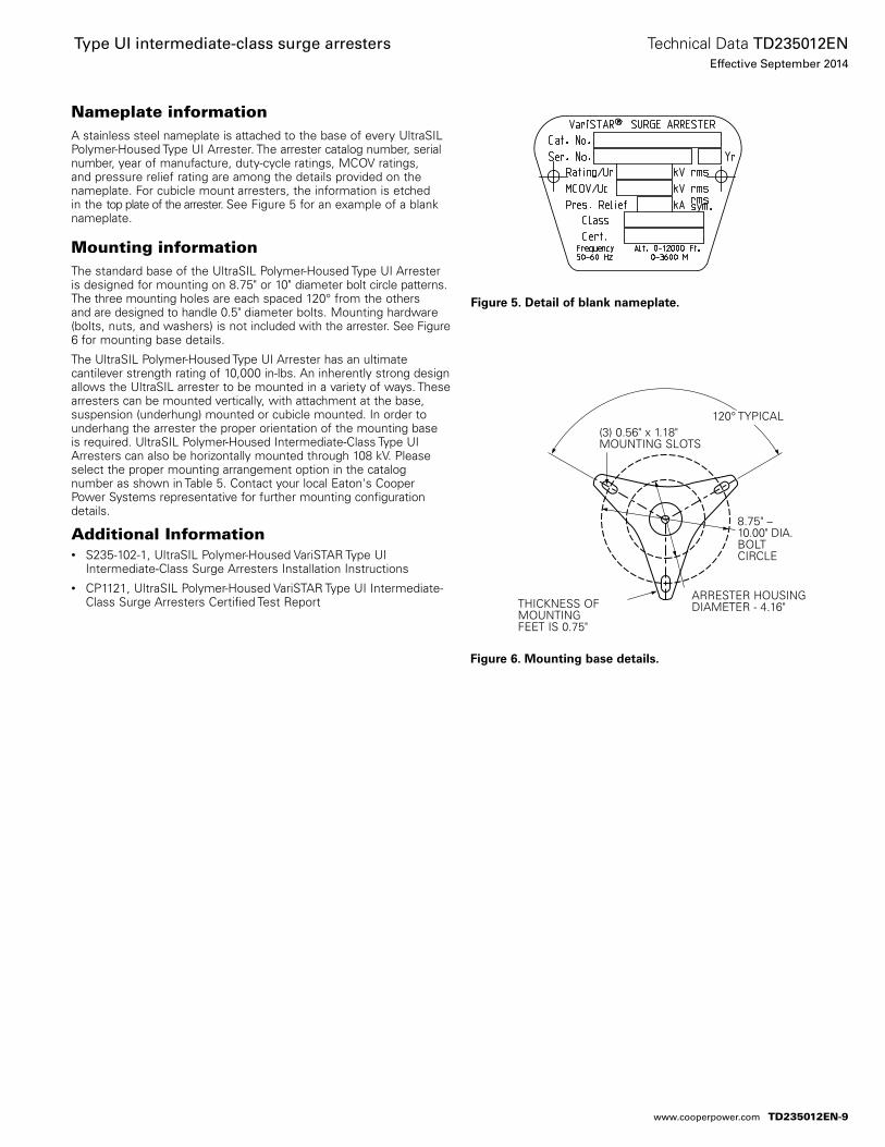
Nameplate informationA stainless steel nameplate is at tached to the base of every UltraSIL Polymer-Housed Type UI Arrester. The arrester catalog number, serial number, year of manufacture, duty-cycle ratings, MCOV ratings, and pressure relief rating are among the details provided on the nameplate. For cubicle mount arresters, the information is etched in the top plate of the arrester. See Figure 5 for an example of a blank nameplate.
Mounting informationThe standard base of the UltraSIL Polymer-Housed Type UI Arrester is designed for mounting on 8.75" or 10" diameter bolt circle patterns. The three mounting holes are each spaced 120° from the others and are designed to handle 0.5" diameter bolts. Mounting hardware (bolts, nuts, and washers) is not in cluded with the arrester. See Figure 6 for mounting base details.
The UltraSIL Polymer-Housed Type UI Arrester has an ultimate cantilever strength rating of 10,000 in-lbs. An inherently strong design allows the UltraSIL arrester to be mounted in a variety of ways. These arresters can be mounted ver tically, with attachment at the base, suspension (underhung) mounted or cubicle mounted. In order to underhang the arrester the proper ori entation of the mounting base is required. UltraSIL Polymer-Housed Intermediate-Class Type UI Arresters can also be horizontally mounted through 108 kV. Please select the proper mounting arrangement option in the catalog number as shown in Table 5. Contact your local Eaton's Cooper Power Systems representative for further mounting configuration details.
Additional Information• S235-102-1, UltraSIL Polymer-Housed VariSTAR Type UI
Intermediate-Class Surge Arresters Installation Instructions• CP1121, UltraSIL Polymer-Housed VariSTAR Type UI Intermediate-
Class Surge Arresters Certified Test Report
Figure 5. Detail of blank nameplate.
Figure 6. Mounting base details.
(3) 0.56" x 1.18" MOUNTING SLOTS
THICKNESS OF MOUNTING FEET IS 0.75"
ARRESTER HOUSING DIAMETER - 4.16"
8.75" – 10.00" DIA. BOLT CIRCLE
120° TYPICAL
TD235012EN-9
Technical Data TD235012ENEffective September 2014
Type UI intermediate-class surge arresters
www.cooperpower.com
TD235012EN-10
Technical Data TD235012ENEffective September 2014
Type UI intermediate-class surge arresters
www.cooperpower.com
TD235012EN-11
Technical Data TD235012ENEffective September 2014
Type UI intermediate-class surge arresters
www.cooperpower.com
Type UI intermediate-class surge arrestersTechnical Data TD235012ENEffective September 2014
Eaton, Cooper Power Systems, VariSTAR and UltraSIL are valuable trademarks of Eaton in the U.S. and other countries. You are not permitted to use these trademarks without the prior written consent of Eaton.IEEE is a registered trademark of the Institute of Electrical and Electronics Engineers, Inc.IEEE Std C62.11™-2005, IEEE Std C62.22™-2009 and IEEE Std 62.11a™-2008 standards are trademarks of the Institute of Electrical and Electronics Engineers, Inc., (IEEE). This publication/product is not endorsed or approved by the IEEE.
Eaton1000 Eaton BoulevardCleveland, OH 44122United StatesEaton.com
Eaton’s Cooper Power Systems Business2300 Badger DriveWaukesha, WI 53188United StatesCooperpower.com
© 2014 EatonAll Rights ReservedPrinted in USAPublication No. TD235012EN
For Eaton's Cooper Power Systems surge arrester product information call 1-877-277-4636 or visit: www.cooperpower.com.
TD235012EN-12
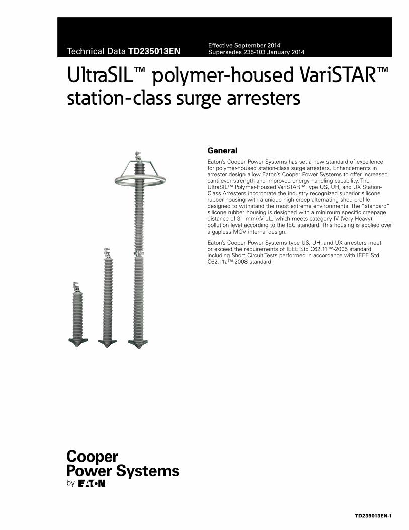
UltraSIL™ polymer-housed VariSTAR™ station-class surge arresters
GeneralEaton’s Cooper Power Systems has set a new standard of excellence for polymer-housed station-class surge arresters. Enhancements in arrester design allow Eaton’s Cooper Power Systems to offer increased cantilever strength and improved energy handling capability. The UltraSIL™ Polymer-Housed VariSTAR™ Type US, UH, and UX Station-Class Arresters incorporate the industry recognized superior silicone rubber housing with a unique high creep alternating shed profile designed to withstand the most extreme environments. The “standard” silicone rubber housing is designed with a minimum specific creepage distance of 31 mm/kV L-L, which meets category IV (Very Heavy) pollution level according to the IEC standard. This housing is applied over a gapless MOV internal design.
Eaton’s Cooper Power Systems type US, UH, and UX arresters meet or exceed the requirements of IEEE Std C62.11™-2005 standard including Short Circuit Tests performed in accordance with IEEE Std C62.11a™-2008 standard.
Technical Data TD235013ENEffective September 2014Supersedes 235-103 January 2014
TD235013EN-1
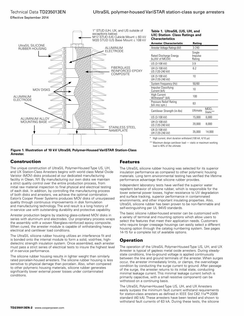
ConstructionThe unique construction of UltraSIL Polymer-Housed Type US, UH, and UX Station-Class Arresters begins with world class Metal Oxide Varistor (MOV) disks produced at our dedicated manufacturing facility in Olean, NY. By manufacturing our own disks we maintain a strict quality control over the entire pro duction process, from initial raw material inspection to final physical and electrical testing of each disk. In addition, by controlling the manufacturing process of both disks and arresters, we achieve the optimal combination. Eaton’s Cooper Power Systems produces MOV disks of unsurpassed quality through continuous improvements in disk formulation and manufacturing technology. The end result is a long history of in-service use with outstanding durability and protective capability.
Arrester production begins by stacking glass-collared MOV disks in series with aluminum end electrodes. Our proprietary process wraps the assembly with a woven fiberglass-reinforced epoxy composite. When cured, the arrester module is capable of withstanding heavy electrical and cantilever load conditions.
The UltraSIL silicone rubber housing utilizes an inter ference fit and is bonded onto the internal module to form a solid, void-free, high-dielectric strength insulation system. Once assembled, each arrester must pass a strict series of electrical tests to insure the highest level of in-service performance.
The silicone rubber housing results in lighter weight than similarly rated porcelain-housed arresters. The silicone rubber housing is less sensitive to physical damage than porcelain. Also, when compared to other polymeric housing materials, silicone rubber generates significantly lower external power losses under contaminated conditions.
FeaturesThe UltraSIL silicone rubber housing was selected for its superior insula tion performance as compared to other polymeric housing materials. Long term environmental testing has verified the lifetime performance advantage that silicone rubber provides.
Independent laboratory tests have verified the superior water repellent behavior of silicone rubber, which is responsible for the lower external power losses, higher resistance to UV degradation and surface tracking, superior performance in contaminated environments, and other important insulating properties. Also, UltraSIL silicone rubber has been proven to be non-flammable and self-extinguishing per UL 94V0 standards.
The basic silicone rubber-housed arrester can be customized with a variety of terminal and mounting options which allow users to select the features that meet their application needs. Customers who require longer creepage housings can easily select a different housing option through the catalog numbering system. See pages 14-15 for a complete list of available options.
OperationThe operation of the UltraSIL Polymer-Housed Type US, UH, and UX Arrester is typical of gapless metal oxide arresters. During steady-state conditions, line-to-ground voltage is applied con tinuously between the line and ground terminals of the arrester. When surges occur, the arrester immediately limits, or clamps, the overvoltage condition by conducting the surge current to ground. After passage of the surge, the arrester returns to its initial state, conducting minimal leakage current. This minimal leakage current (which is primarily capacitive, with a small resistive component) can be withstood on a continuing basis.
The UltraSIL Polymer-Housed Type US, UH, and UX Arresters easily surpass the minimum fault current withstand requirements for station-class arresters as defined in IEEE Std C62.11a™-2008 standard (40 kA). These arresters have been tested and shown to withstand fault currents of 63 kA. During these tests, the silicone
Figure 1. Illustration of 10 kV UltraSIL Polymer-Housed VariSTAR Station-Class Arrester.
UltraSIL SILICONE RUBBER HOUSING
STAINLESS STEEL NAMEPLATE
ALUMINUM ALLOY MOUNTING BASE
FIBERGLASS REINFORCED EPOXY COMPOSITE
MOV DISKS
ALUMINUM ELECTRODE
ALUMINUM ELECTRODE
* High current, short duration withstand (100 kA, 4/10 µs)
** Maximum design cantilever load — static or maximum working load is 40% of the ultimate.
Table 1. UltraSIL (US, UH, and UX) Station- Class Ratings and CharacteristicsArrester Characteristic Rating
Arrester Voltage Ratings (kV) 3-240
Rated Discharge Energy(kJ/kV of MCOV)
SingleImpulseRating
US (3-108 kV) 3.9UH (3-108 kV)US (120-240 kV)
6.2
UX (3-108 kV)UH (120-240 kV)
10
System Frequency (Hz) 50/60Impulse Classifying Current (kA) 10
High Current Withstand* (kA) 100
Pressure Relief Rating (kA rms sym.) 63
Cantilever Strength (in-Ibs) Ultimate MDCL-Static**
US (3-108 kV) 15,000 6,000UH (3-108 kV)US (120-240 kV) 20,000 8,000
UX (3-108 kV)UH (120-240 kV) 35,000 14,000
1” STUD (UH, UX, and US outside of exceptions below) M12 STUD (US Cubicle Mount ≤ 60 kV M20 STUD (US Base Mount ≤ 108 kV
TD235013EN-2
Technical Data TD235013ENEffective September 2014
UltraSIL polymer-housed VariSTAR station-class surge arresters
www.cooperpower.com
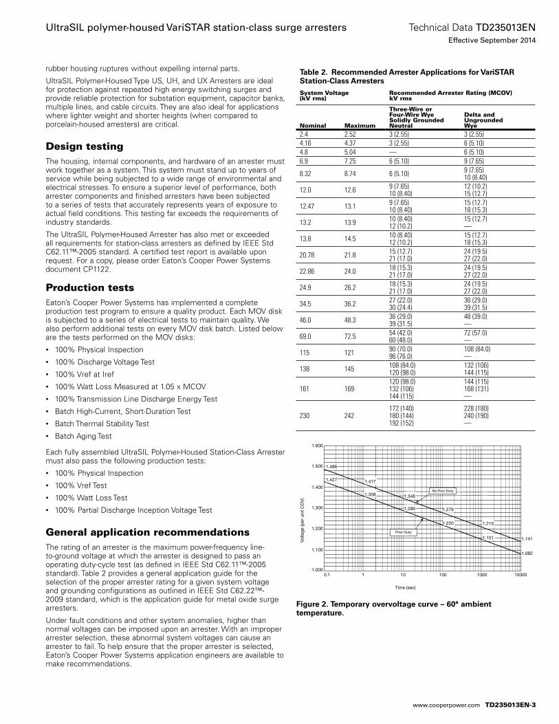
rubber housing ruptures without expelling internal parts.
UltraSIL Polymer-Housed Type US, UH, and UX Arresters are ideal for protection against repeated high energy switching surges and provide reliable protection for substation equipment, capacitor banks, multiple lines, and cable circuits. They are also ideal for applications where lighter weight and shorter heights (when compared to porcelain-housed arresters) are critical.
Design testingThe housing, internal components, and hardware of an arrester must work together as a system. This system must stand up to years of service while being subjected to a wide range of environmental and electrical stresses. To ensure a superior level of performance, both arrester components and finished arresters have been subjected to a series of tests that accurately represents years of exposure to actual field conditions. This testing far exceeds the requirements of industry standards.
The UltraSIL Polymer-Housed Arrester has also met or exceeded all require ments for station-class arresters as defined by IEEE Std C62.11™-2005 standard. A certified test report is available upon request. For a copy, please order Eaton’s Cooper Power Systems document CP1122.
Production testsEaton’s Cooper Power Systems has implemented a complete production test program to ensure a quality product. Each MOV disk is subjected to a series of electrical tests to maintain quality. We also perform additional tests on every MOV disk batch. Listed below are the tests performed on the MOV disks:• 100% Physical Inspection• 100% Discharge Voltage Test• 100% Vref at Iref• 100% Watt Loss Measured at 1.05 x MCOV• 100% Transmission Line Discharge Energy Test• Batch High-Current, Short-Duration Test• Batch Thermal Stability Test• Batch Aging Test
Each fully assembled UltraSIL Polymer-Housed Station-Class Arrester must also pass the following production tests:• 100% Physical Inspection• 100% Vref Test• 100% Watt Loss Test• 100% Partial Discharge Inception Voltage Test
General application recommendationsThe rating of an arrester is the maximum power-frequency line-to-ground voltage at which the arrester is designed to pass an operating duty-cycle test (as defined in IEEE Std C62.11™-2005 standard). Table 2 provides a general application guide for the selection of the proper arrester rating for a given system voltage and grounding configurations as outlined in IEEE Std C62.22™-2009 standard, which is the application guide for metal oxide surge arresters.
Under fault conditions and other system anomalies, higher than normal voltages can be imposed upon an arrester. With an improper arrester selection, these abnormal system voltages can cause an arrester to fail. To help ensure that the proper arrester is selected, Eaton’s Cooper Power Systems application engineers are available to make recommendations.
Table 2. Recommended Arrester Applications for VariSTAR Station-Class ArrestersSystem Voltage (kV rms)
Recommended Arrester Rating (MCOV)kV rms
Nominal Maximum
Three-Wire orFour-Wire Wye Solidly GroundedNeutral
Delta and UngroundedWye
2.4 2.52 3 (2.55) 3 (2.55)4.16 4.37 3 (2.55) 6 (5.10)4.8 5.04 — 6 (5.10)6.9 7.25 6 (5.10) 9 (7.65)
8.32 8.74 6 (5.10) 9 (7.65)10 (8.40)
12.0 12.6 9 (7.65)10 (8.40)
12 (10.2)15 (12.7)
12.47 13.1 9 (7.65)10 (8.40)
15 (12.7)18 (15.3)
13.2 13.9 10 (8.40)12 (10.2)
15 (12.7)—
13.8 14.5 10 (8.40)12 (10.2)
15 (12.7)18 (15.3)
20.78 21.8 15 (12.7)21 (17.0)
24 (19.5)27 (22.0)
22.86 24.0 18 (15.3)21 (17.0)
24 (19.5)27 (22.0)
24.9 26.2 18 (15.3)21 (17.0)
24 (19.5)27 (22.0)
34.5 36.2 27 (22.0)30 (24.4)
36 (29.0)39 (31.5)
46.0 48.3 36 (29.0)39 (31.5)
48 (39.0)—
69.0 72.5 54 (42.0)60 (48.0)
72 (57.0)—
115 121 90 (70.0)96 (76.0)
108 (84.0)—
138 145 108 (84.0)120 (98.0)
132 (106)144 (115)
161 169120 (98.0)132 (106)144 (115)
144 (115)168 (131)—
230 242172 (140)180 (144)192 (152)
228 (180)240 (190)—
Figure 2. Temporary overvoltage curve – 60° ambient temperature.
1.600
1.500
1.400
1.300
1.200
1.100
1.000
1.486
1.417
1.348
1.279
1.210
1.141
1.427
1.358
1.289
1.220
1.151
1.082
0.1 1 10 100 1000 10000
Time (sec)
Volta
ge (p
er u
nit C
OV
)
No Prior Duty
Prior Duty
TD235013EN-3
Technical Data TD235013ENEffective September 2014
UltraSIL polymer-housed VariSTAR station-class surge arresters
www.cooperpower.com
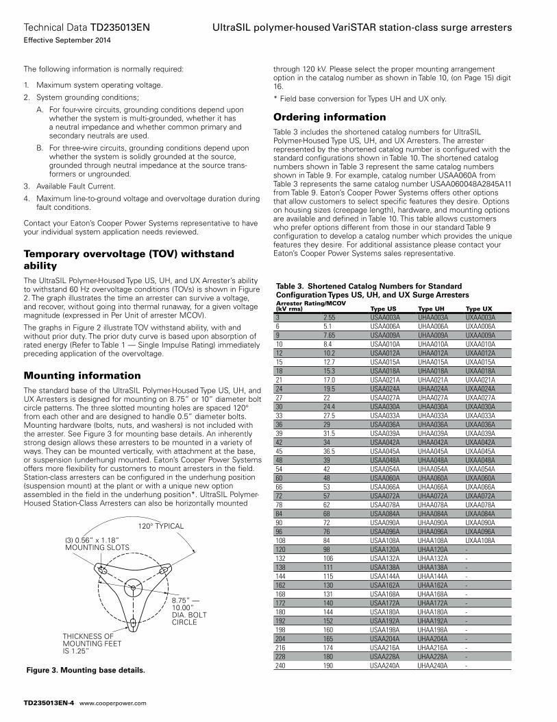
The following information is normally required:
1. Maximum system operating voltage.
2. System grounding conditions;
A. For four-wire circuits, grounding conditions depend upon whether the system is multi-grounded, whether it has a neutral impedance and whether common primary and secondary neutrals are used.
B. For three-wire circuits, grounding conditions depend upon whether the system is solidly grounded at the source, grounded through neutral impedance at the source trans-formers or ungrounded.
3. Available Fault Current.
4. Maximum line-to-ground voltage and overvoltage duration during fault conditions.
Contact your Eaton’s Cooper Power Systems representative to have your individual system application needs reviewed.
Temporary overvoltage (TOV) withstand abilityThe UltraSIL Polymer-Housed Type US, UH, and UX Arrester’s ability to withstand 60 Hz overvoltage conditions (TOVs) is shown in Figure 2. The graph illustrates the time an arrester can survive a voltage, and recover, without going into thermal runaway, for a given voltage magnitude (expressed in Per Unit of arrester MCOV).
The graphs in Figure 2 illustrate TOV withstand ability, with and without prior duty. The prior duty curve is based upon absorption of rated energy (Refer to Table 1 — Single Impulse Rating) immediately preceding application of the overvoltage.
Mounting informationThe standard base of the UltraSIL Polymer-Housed Type US, UH, and UX Arresters is designed for mounting on 8.75” or 10” diameter bolt circle patterns. The three slotted mounting holes are spaced 120° from each other and are designed to handle 0.5” diameter bolts. Mounting hardware (bolts, nuts, and washers) is not in cluded with the arrester. See Figure 3 for mounting base details. An inherently strong design allows these arresters to be mounted in a variety of ways. They can be mounted vertically, with attachment at the base, or suspension (underhung) mounted. Eaton’s Cooper Power Systems offers more flexibility for customers to mount arresters in the field. Station-class arresters can be configured in the underhung position (suspension mount) at the plant or with a unique new option assembled in the field in the underhung position*. UltraSIL Polymer-Housed Station-Class Arresters can also be horizontally mounted
through 120 kV. Please select the proper mounting arrangement option in the catalog number as shown in Table 10, (on Page 15) digit 16.
* Field base conversion for Types UH and UX only.
Ordering informationTable 3 includes the shortened catalog numbers for UltraSIL Polymer-Housed Type US, UH, and UX Arresters. The arrester represented by the shortened catalog number is configured with the standard configurations shown in Table 10. The shortened catalog numbers shown in Table 3 represent the same catalog numbers shown in Table 9. For example, catalog number USAA060A from Table 3 represents the same catalog number USAA060048A2845A11 from Table 9. Eaton’s Cooper Power Systems offers other options that allow customers to select specific features they desire. Options on housing sizes (creepage length), hardware, and mounting options are available and defined in Table 10. This table allows customers who prefer options different from those in our standard Table 9 configuration to develop a catalog number which provides the unique features they desire. For additional assistance please contact your Eaton’s Cooper Power Systems sales representative.
Figure 3. Mounting base details.
(3) 0.56” x 1.18” MOUNTING SLOTS
THICKNESS OF MOUNTING FEET IS 1.25”
8.75” — 10.00” DIA. BOLT CIRCLE
120° TYPICAL
Table 3. Shortened Catalog Numbers for Standard Configuration Types US, UH, and UX Surge ArrestersArrester Rating/MCOV (kV rms) Type US Type UH Type UX3 2.55 USAA003A UHAA003A UXAA003A 6 5.1 USAA006A UHAA006A UXAA006A 9 7.65 USAA009A UHAA009A UXAA009A 10 8.4 USAA010A UHAA010A UXAA010A 12 10.2 USAA012A UHAA012A UXAA012A 15 12.7 USAA015A UHAA015A UXAA015A 18 15.3 USAA018A UHAA018A UXAA018A 21 17.0 USAA021A UHAA021A UXAA021A 24 19.5 USAA024A UHAA024A UXAA024A 27 22 USAA027A UHAA027A UXAA027A 30 24.4 USAA030A UHAA030A UXAA030A 33 27.5 USAA033A UHAA033A UXAA033A 36 29 USAA036A UHAA036A UXAA036A 39 31.5 USAA039A UHAA039A UXAA039A 42 34 USAA042A UHAA042A UXAA042A 45 36.5 USAA045A UHAA045A UXAA045A 48 39 USAA048A UHAA048A UXAA048A 54 42 USAA054A UHAA054A UXAA054A 60 48 USAA060A UHAA060A UXAA060A 66 53 USAA066A UHAA066A UXAA066A 72 57 USAA072A UHAA072A UXAA072A 78 62 USAA078A UHAA078A UXAA078A 84 68 USAA084A UHAA084A UXAA084A 90 72 USAA090A UHAA090A UXAA090A 96 76 USAA096A UHAA096A UXAA096A 108 84 USAA108A UHAA108A UXAA108A 120 98 USAA120A UHAA120A -132 106 USAA132A UHAA132A -138 111 USAA138A UHAA138A -144 115 USAA144A UHAA144A -162 130 USAA162A UHAA162A -168 131 USAA168A UHAA168A -172 140 USAA172A UHAA172A -180 144 USAA180A UHAA180A -192 152 USAA192A UHAA192A -198 160 USAA198A UHAA198A -204 165 USAA204A UHAA204A -216 174 USAA216A UHAA216A -228 180 USAA228A UHAA228A -240 190 USAA240A UHAA240A -
TD235013EN-4
Technical Data TD235013ENEffective September 2014
UltraSIL polymer-housed VariSTAR station-class surge arresters
www.cooperpower.com
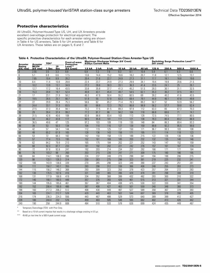
Protective characteristicsAll UltraSIL Polymer-Housed Type US, UH, and UX Arresters provide excellent overvoltage protection for electrical equipment. The specific protective characteristics for each arrester rating are shown in Table 4 for US arresters, Table 5 for UH arresters and Table 6 for UX Arresters. These tables are on pages 5, 6 and 7.
* Temporary Overvoltage (TOV) with Prior Duty.
** Based on a 10 kA current impulse that results in a discharge voltage cresting in 0.5 µs.
*** 45-60 µs rise time for a 500 A peak current surge.
Table 4. Protective Characteristics of the UltraSIL Polymer-Housed Station-Class Arrester-Type US
Arrester Rating (kV, rms)
Arrester MCOV (kV rms)
TOV* Front-of-wave Protective Level**(kV Crest)
Maximum Discharge Voltage (kV Crest)8/20µs Current Wave
Switching Surge Protective Level***(kV crest)
1 Sec10 Sec 1.5 kA 3 kA 5 kA 10 kA 20 kA 40 kA 125 A 250 A 500 A 1000 A
3 2.55 3.5 3.3 8.8 6.8 7.2 7.6 8.3 9.1 10.4 5.9 6.1 6.3 6.66 5.1 6.9 6.6 17.5 13.6 14.4 15.2 16.6 18.2 20.7 11.8 12.1 12.5 13.19 7.65 10.4 9.9 26.2 20.4 21.6 22.7 24.9 27.3 31.1 17.7 18.1 18.8 19.610 8.4 11.4 10.8 28.8 22.4 23.7 24.9 27.3 29.9 34.1 19.4 19.9 20.6 21.512 10.2 13.9 13.1 34.9 27.2 28.8 30.3 33.1 36.3 41.4 23.5 24.1 25 26.115 12.7 17.2 16.4 43.5 33.8 35.8 37.7 41.3 45.2 51.5 29.3 30.1 31.1 32.518 15.3 20.8 19.7 52.4 40.8 43.1 45.4 49.7 54.5 62.1 35.3 36.2 37.5 39.121 17 23.1 21.9 58.2 45.3 47.9 50.4 55.2 60.5 69 39.2 40.2 41.6 43.524 19.5 26.5 25.1 66.7 51.9 55 57.8 63.3 69.4 79.1 44.9 46.1 47.8 49.827 22 29.9 28.4 75.3 58.6 62 65.2 71.4 78.3 89.2 50.7 52 53.9 56.230 24.4 33.1 31.5 83.5 65 68.8 72.3 79.2 86.8 98.9 56.2 57.7 59.8 62.433 27.5 37.3 35.4 94.1 73.2 77.5 81.5 89.3 97.9 112 63.3 65 67.3 70.336 29 39.4 37.4 99.2 77.2 81.7 86 94.2 104 118 66.8 68.6 71 74.139 31.5 42.8 40.6 108 83.9 88.8 93.4 103 113 128 72.5 74.5 77.1 80.542 34 46.2 43.8 117 90.5 95.8 101 111 121 138 78.3 80.4 83.2 86.945 36.5 49.6 47 125 97.2 103 109 119 130 148 84 86.3 89.4 93.348 39 53 50.3 134 104 110 116 127 139 159 89.8 92.2 95.5 99.654 42 57 54.1 144 112 119 125 137 150 171 96.7 99.3 103 10860 48 65.2 61.9 165 128 136 143 156 171 195 111 114 118 12366 53 72 68.3 182 142 150 158 172 189 215 122 126 130 13672 57 77.4 73.5 195 152 161 169 185 203 232 132 135 140 14678 62 84.2 79.9 213 165 175 184 202 221 252 143 147 152 15984 68 92.3 87.7 233 181 192 202 221 242 276 157 161 167 17490 72 97.8 92.8 247 192 203 214 234 257 292 166 171 177 18496 76 103.2 98 260 203 215 226 247 271 309 175 180 186 195108 84 114.1 108.3 288 224 237 249 273 299 341 194 199 206 215120 98 133.1 126.3 314 250 263 275 298 323 361 219 225 232 241132 106 143.9 136.6 339 270 285 298 323 349 390 237 243 251 261138 111 150.7 143.1 355 283 298 312 338 366 408 248 255 263 273144 115 156.2 148.2 368 293 309 323 350 379 423 257 264 272 283162 130 176.5 167.6 416 331 349 365 396 429 478 291 298 308 319168 131 177.9 168.9 419 334 352 368 399 432 482 293 300 310 322172 140 190.1 180.5 448 357 376 393 426 461 515 313 321 331 344180 144 195.6 185.6 461 367 387 404 438 475 530 322 330 341 354192 152 206.4 195.9 486 387 408 427 463 501 559 340 348 360 373198 160 217.3 206.2 512 408 430 449 487 527 589 358 367 378 393204 165 224.1 212.7 528 420 443 463 502 544 607 369 378 390 405216 174 236.3 224.3 556 443 467 488 529 573 640 389 399 412 427228 180 244.4 232 576 459 483 505 548 593 662 402 413 426 442240 190 258 244.9 608 484 510 533 578 626 699 424 435 449 467
TD235013EN-5
Technical Data TD235013ENEffective September 2014
UltraSIL polymer-housed VariSTAR station-class surge arresters
www.cooperpower.com
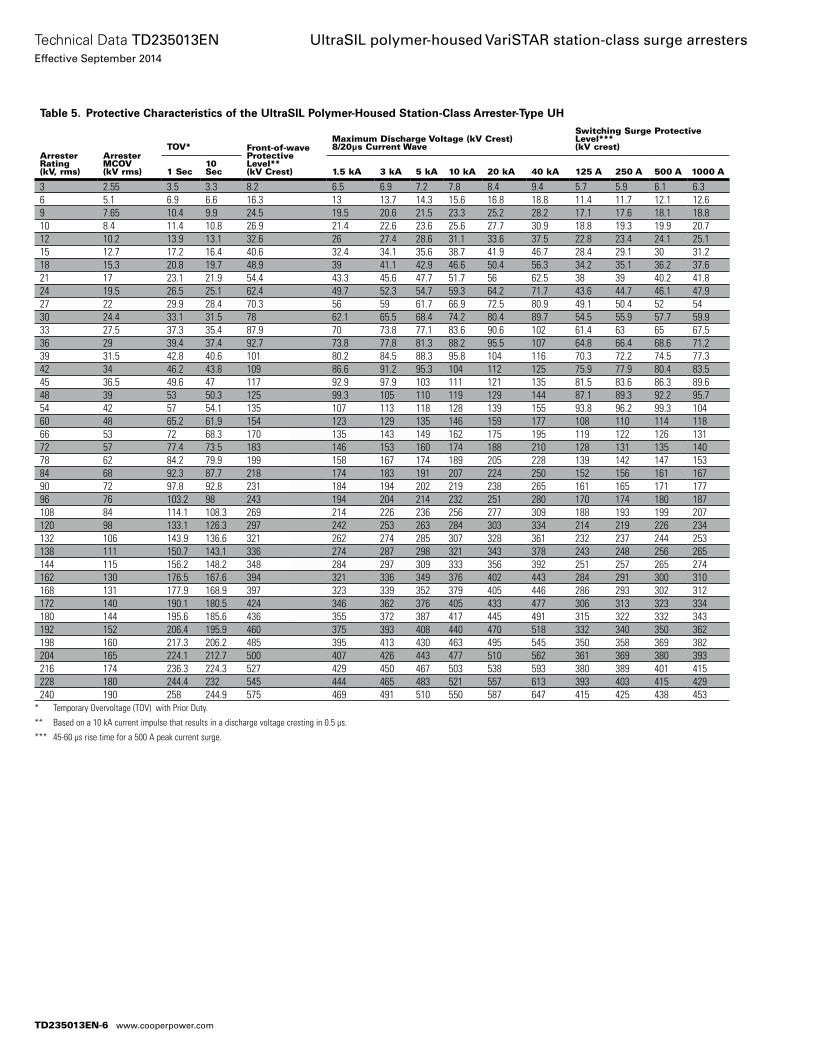
* Temporary Overvoltage (TOV) with Prior Duty.
** Based on a 10 kA current impulse that results in a discharge voltage cresting in 0.5 µs.
*** 45-60 µs rise time for a 500 A peak current surge.
Table 5. Protective Characteristics of the UltraSIL Polymer-Housed Station-Class Arrester-Type UH
Arrester Rating (kV, rms)
Arrester MCOV (kV rms)
TOV* Front-of-wave Protective Level**(kV Crest)
Maximum Discharge Voltage (kV Crest)8/20μs Current Wave
Switching Surge Protective Level*** (kV crest)
1 Sec10 Sec 1.5 kA 3 kA 5 kA 10 kA 20 kA 40 kA 125 A 250 A 500 A 1000 A
3 2.55 3.5 3.3 8.2 6.5 6.9 7.2 7.8 8.4 9.4 5.7 5.9 6.1 6.36 5.1 6.9 6.6 16.3 13 13.7 14.3 15.6 16.8 18.8 11.4 11.7 12.1 12.69 7.65 10.4 9.9 24.5 19.5 20.6 21.5 23.3 25.2 28.2 17.1 17.6 18.1 18.810 8.4 11.4 10.8 26.9 21.4 22.6 23.6 25.6 27.7 30.9 18.8 19.3 19.9 20.712 10.2 13.9 13.1 32.6 26 27.4 28.6 31.1 33.6 37.5 22.8 23.4 24.1 25.115 12.7 17.2 16.4 40.6 32.4 34.1 35.6 38.7 41.9 46.7 28.4 29.1 30 31.218 15.3 20.8 19.7 48.9 39 41.1 42.9 46.6 50.4 56.3 34.2 35.1 36.2 37.621 17 23.1 21.9 54.4 43.3 45.6 47.7 51.7 56 62.5 38 39 40.2 41.824 19.5 26.5 25.1 62.4 49.7 52.3 54.7 59.3 64.2 71.7 43.6 44.7 46.1 47.927 22 29.9 28.4 70.3 56 59 61.7 66.9 72.5 80.9 49.1 50.4 52 5430 24.4 33.1 31.5 78 62.1 65.5 68.4 74.2 80.4 89.7 54.5 55.9 57.7 59.933 27.5 37.3 35.4 87.9 70 73.8 77.1 83.6 90.6 102 61.4 63 65 67.536 29 39.4 37.4 92.7 73.8 77.8 81.3 88.2 95.5 107 64.8 66.4 68.6 71.239 31.5 42.8 40.6 101 80.2 84.5 88.3 95.8 104 116 70.3 72.2 74.5 77.342 34 46.2 43.8 109 86.6 91.2 95.3 104 112 125 75.9 77.9 80.4 83.545 36.5 49.6 47 117 92.9 97.9 103 111 121 135 81.5 83.6 86.3 89.648 39 53 50.3 125 99.3 105 110 119 129 144 87.1 89.3 92.2 95.754 42 57 54.1 135 107 113 118 128 139 155 93.8 96.2 99.3 10460 48 65.2 61.9 154 123 129 135 146 159 177 108 110 114 11866 53 72 68.3 170 135 143 149 162 175 195 119 122 126 13172 57 77.4 73.5 183 146 153 160 174 188 210 128 131 135 14078 62 84.2 79.9 199 158 167 174 189 205 228 139 142 147 15384 68 92.3 87.7 218 174 183 191 207 224 250 152 156 161 16790 72 97.8 92.8 231 184 194 202 219 238 265 161 165 171 17796 76 103.2 98 243 194 204 214 232 251 280 170 174 180 187108 84 114.1 108.3 269 214 226 236 256 277 309 188 193 199 207120 98 133.1 126.3 297 242 253 263 284 303 334 214 219 226 234132 106 143.9 136.6 321 262 274 285 307 328 361 232 237 244 253138 111 150.7 143.1 336 274 287 298 321 343 378 243 248 256 265144 115 156.2 148.2 348 284 297 309 333 356 392 251 257 265 274162 130 176.5 167.6 394 321 336 349 376 402 443 284 291 300 310168 131 177.9 168.9 397 323 339 352 379 405 446 286 293 302 312172 140 190.1 180.5 424 346 362 376 405 433 477 306 313 323 334180 144 195.6 185.6 436 355 372 387 417 445 491 315 322 332 343192 152 206.4 195.9 460 375 393 408 440 470 518 332 340 350 362198 160 217.3 206.2 485 395 413 430 463 495 545 350 358 369 382204 165 224.1 212.7 500 407 426 443 477 510 562 361 369 380 393216 174 236.3 224.3 527 429 450 467 503 538 593 380 389 401 415228 180 244.4 232 545 444 465 483 521 557 613 393 403 415 429240 190 258 244.9 575 469 491 510 550 587 647 415 425 438 453
TD235013EN-6
Technical Data TD235013ENEffective September 2014
UltraSIL polymer-housed VariSTAR station-class surge arresters
www.cooperpower.com
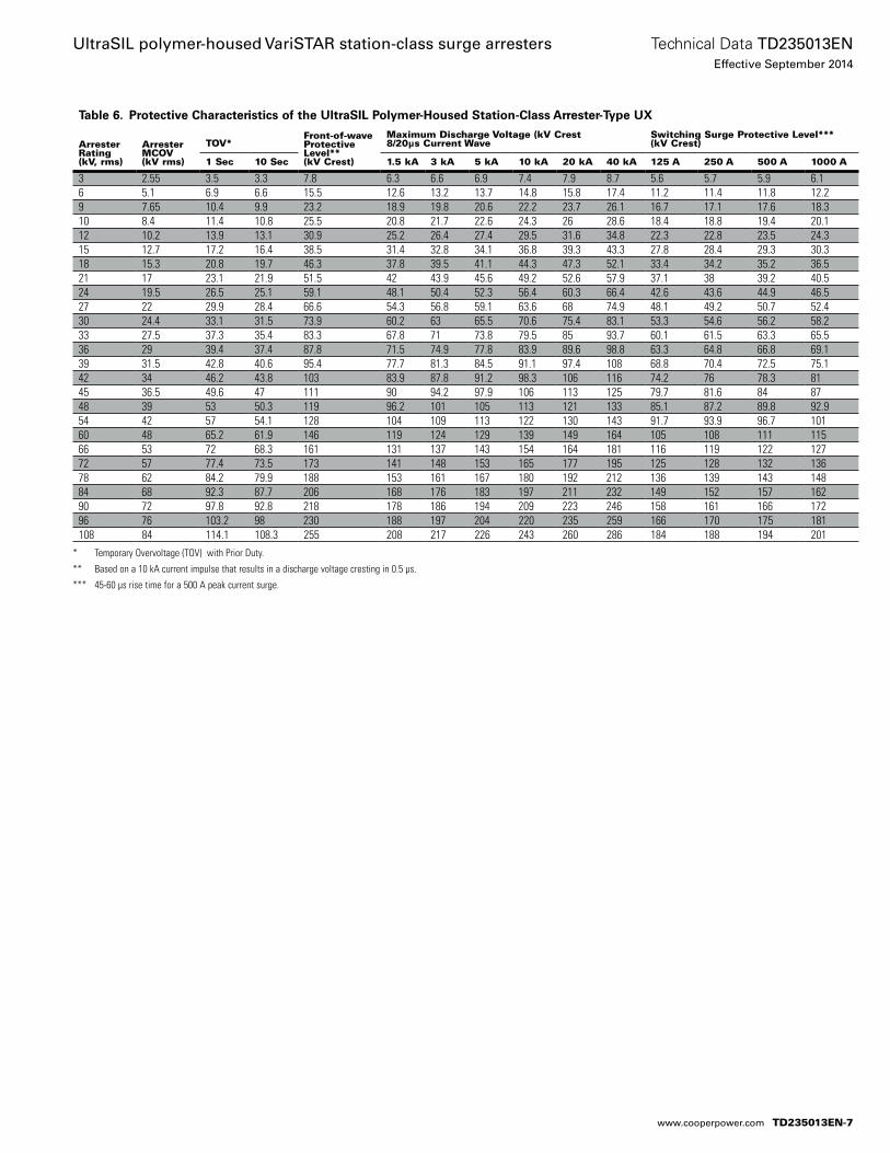
* Temporary Overvoltage (TOV) with Prior Duty.
** Based on a 10 kA current impulse that results in a discharge voltage cresting in 0.5 µs.
*** 45-60 µs rise time for a 500 A peak current surge.
Table 6. Protective Characteristics of the UltraSIL Polymer-Housed Station-Class Arrester-Type UX
Arrester Rating (kV, rms)
Arrester MCOV (kV rms)
TOV*Front-of-wave Protective Level** (kV Crest)
Maximum Discharge Voltage (kV Crest8/20μs Current Wave
Switching Surge Protective Level*** (kV Crest)
1 Sec 10 Sec 1.5 kA 3 kA 5 kA 10 kA 20 kA 40 kA 125 A 250 A 500 A 1000 A
3 2.55 3.5 3.3 7.8 6.3 6.6 6.9 7.4 7.9 8.7 5.6 5.7 5.9 6.16 5.1 6.9 6.6 15.5 12.6 13.2 13.7 14.8 15.8 17.4 11.2 11.4 11.8 12.29 7.65 10.4 9.9 23.2 18.9 19.8 20.6 22.2 23.7 26.1 16.7 17.1 17.6 18.310 8.4 11.4 10.8 25.5 20.8 21.7 22.6 24.3 26 28.6 18.4 18.8 19.4 20.112 10.2 13.9 13.1 30.9 25.2 26.4 27.4 29.5 31.6 34.8 22.3 22.8 23.5 24.315 12.7 17.2 16.4 38.5 31.4 32.8 34.1 36.8 39.3 43.3 27.8 28.4 29.3 30.318 15.3 20.8 19.7 46.3 37.8 39.5 41.1 44.3 47.3 52.1 33.4 34.2 35.2 36.521 17 23.1 21.9 51.5 42 43.9 45.6 49.2 52.6 57.9 37.1 38 39.2 40.524 19.5 26.5 25.1 59.1 48.1 50.4 52.3 56.4 60.3 66.4 42.6 43.6 44.9 46.527 22 29.9 28.4 66.6 54.3 56.8 59.1 63.6 68 74.9 48.1 49.2 50.7 52.430 24.4 33.1 31.5 73.9 60.2 63 65.5 70.6 75.4 83.1 53.3 54.6 56.2 58.233 27.5 37.3 35.4 83.3 67.8 71 73.8 79.5 85 93.7 60.1 61.5 63.3 65.536 29 39.4 37.4 87.8 71.5 74.9 77.8 83.9 89.6 98.8 63.3 64.8 66.8 69.139 31.5 42.8 40.6 95.4 77.7 81.3 84.5 91.1 97.4 108 68.8 70.4 72.5 75.142 34 46.2 43.8 103 83.9 87.8 91.2 98.3 106 116 74.2 76 78.3 8145 36.5 49.6 47 111 90 94.2 97.9 106 113 125 79.7 81.6 84 8748 39 53 50.3 119 96.2 101 105 113 121 133 85.1 87.2 89.8 92.954 42 57 54.1 128 104 109 113 122 130 143 91.7 93.9 96.7 10160 48 65.2 61.9 146 119 124 129 139 149 164 105 108 111 11566 53 72 68.3 161 131 137 143 154 164 181 116 119 122 12772 57 77.4 73.5 173 141 148 153 165 177 195 125 128 132 13678 62 84.2 79.9 188 153 161 167 180 192 212 136 139 143 14884 68 92.3 87.7 206 168 176 183 197 211 232 149 152 157 16290 72 97.8 92.8 218 178 186 194 209 223 246 158 161 166 17296 76 103.2 98 230 188 197 204 220 235 259 166 170 175 181108 84 114.1 108.3 255 208 217 226 243 260 286 184 188 194 201
TD235013EN-7
Technical Data TD235013ENEffective September 2014
UltraSIL polymer-housed VariSTAR station-class surge arresters
www.cooperpower.com
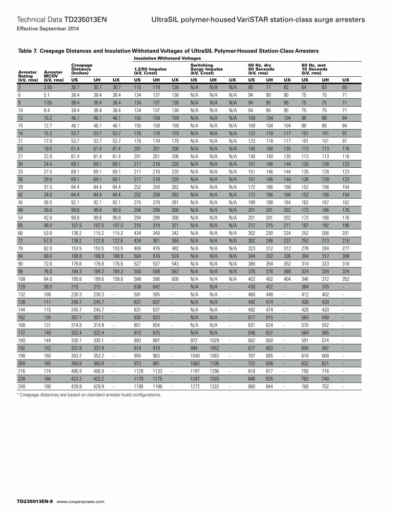
* Creepage distances are based on standard arrester build configurations.
Table 7. Creepage Distances and Insulation Withstand Voltages of UltraSIL Polymer-Housed Station-Class Arresters
Arrester Rating (kV, rms)
Arrester MCOV (kV, rms)
Creepage Distance (Inches)
Insulation Withstand Voltages
1.2/50 Impulse (kV, Crest)
Switching Surge Impulse (kV, Crest)
60 Hz, dry 60 Seconds (kV, rms)
60 Hz, wet 10 Seconds (kV, rms)
US UH UX US UH UX US UH UX US UH UX US UH UX
3 2.55 30.7 30.7 30.7 115 119 126 N/A N/A N/A 80 77 82 64 63 606 5.1 38.4 38.4 38.4 134 137 138 N/A N/A N/A 94 90 90 75 75 719 7.65 38.4 38.4 38.4 134 137 138 N/A N/A N/A 94 90 90 75 75 7110 8.4 38.4 38.4 38.4 134 137 138 N/A N/A N/A 94 90 90 75 75 7112 10.2 46.1 46.1 46.1 155 158 159 N/A N/A N/A 109 104 104 88 88 8415 12.7 46.1 46.1 46.1 155 158 159 N/A N/A N/A 109 104 104 88 88 8418 15.3 53.7 53.7 53.7 176 178 179 N/A N/A N/A 123 118 117 101 101 9721 17.0 53.7 53.7 53.7 176 178 179 N/A N/A N/A 123 118 117 101 101 9724 19.5 61.4 61.4 61.4 201 201 206 N/A N/A N/A 140 140 135 113 113 11627 22.0 61.4 61.4 61.4 201 201 206 N/A N/A N/A 140 140 135 113 113 11630 24.4 69.1 69.1 69.1 217 218 220 N/A N/A N/A 151 146 144 126 128 12333 27.5 69.1 69.1 69.1 217 218 220 N/A N/A N/A 151 146 144 126 128 12336 29.0 69.1 69.1 69.1 217 218 220 N/A N/A N/A 151 146 144 126 128 12339 31.5 84.4 84.4 84.4 252 258 262 N/A N/A N/A 172 166 168 152 156 15442 34.0 84.4 84.4 84.4 252 258 262 N/A N/A N/A 172 166 168 152 156 15445 36.5 92.1 92.1 92.1 275 279 281 N/A N/A N/A 188 188 184 162 167 16248 39.0 99.8 99.8 99.8 294 298 300 N/A N/A N/A 201 201 202 173 186 17654 42.0 99.8 99.8 99.8 294 298 300 N/A N/A N/A 201 201 202 173 186 17660 48.0 107.5 107.5 107.5 316 319 321 N/A N/A N/A 212 215 211 187 192 18866 53.0 138.2 115.2 115.2 434 340 342 N/A N/A N/A 302 230 224 252 206 20172 57.0 138.2 122.8 122.8 434 361 364 N/A N/A N/A 302 246 237 252 213 21078 62.0 153.5 153.5 153.5 469 476 482 N/A N/A N/A 323 312 312 278 284 27784 68.0 168.9 168.9 168.9 504 516 524 N/A N/A N/A 344 332 336 304 312 30890 72.0 176.6 176.6 176.6 527 537 543 N/A N/A N/A 360 354 352 314 323 31696 76.0 184.3 184.3 184.3 550 558 562 N/A N/A N/A 376 376 368 324 334 324108 84.0 199.6 199.6 199.6 588 596 600 N/A N/A N/A 402 402 404 346 372 352120 98.0 215 215 - 638 642 - N/A N/A - 430 422 - 384 376 -132 106 230.3 230.3 - 591 595 - N/A N/A - 460 448 - 412 402 -138 111 245.7 245.7 - 631 637 - N/A N/A - 492 474 - 426 420 -144 115 245.7 245.7 - 631 637 - N/A N/A - 492 474 - 426 420 -162 130 307.1 307.1 - 830 833 - N/A N/A - 617 615 - 564 540 -168 131 314.8 314.8 - 851 854 - N/A N/A - 631 624 - 570 552 -172 140 322.4 322.4 - 872 875 - N/A N/A - 646 637 - 584 565 -180 144 330.1 330.1 - 893 897 - 972 1029 - 662 650 - 591 574 -192 152 337.8 337.8 - 914 918 - 994 1052 - 677 663 - 605 587 -198 160 353.2 353.2 - 955 963 - 1040 1083 - 707 685 - 618 608 -204 165 360.8 360.8 - 973 981 - 1062 1106 - 722 698 - 632 621 -216 174 406.9 406.9 - 1128 1133 - 1197 1296 - 818 817 - 750 716 -228 180 422.2 422.2 - 1170 1175 - 1247 1320 - 846 835 - 762 740 -240 190 429.9 429.9 - 1190 1198 - 1272 1332 - 860 844 - 768 752 -
TD235013EN-8
Technical Data TD235013ENEffective September 2014
UltraSIL polymer-housed VariSTAR station-class surge arresters
www.cooperpower.com
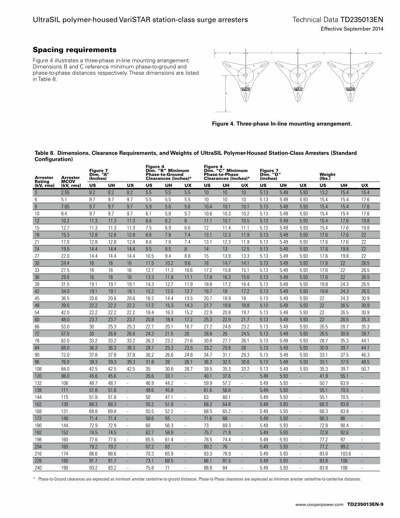
* Phase-to-Ground clearances are expressed as minimum arrester centerline-to-ground distances. Phase-to-Phase clearances are expressed as minimum arrester centerline-to-centerline distances.
Table 8. Dimensions, Clearance Requirements, and Weights of UltraSIL Polymer-Housed Station-Class Arresters (Standard Configuration)
Arrester Rating (kV, rms)
Arrester MCOV (kV, rms)
Figure 7 Dim. “A” (Inches)
Figure 4 Dim. “B” Minimum Phase-to-Ground Clearances (inches)*
Figure 4 Dim. “C” Minimum Phase-to-Phase Clearances (inches)*
Figure 7 Dim. “D” (inches)
Weight (lbs.)
US UH UX US UH UX US UH UX US UH UX US UH UX
3 2.55 8.2 8.2 8.2 5.5 5.5 5.5 10 10 10 5.13 5.49 5.93 13.2 15.4 15.46 5.1 9.7 9.7 9.7 5.5 5.5 5.5 10 10 10 5.13 5.49 5.93 15.4 15.4 17.69 7.65 9.7 9.7 9.7 5.9 5.6 5.6 10.4 10.1 10.1 5.13 5.49 5.93 15.4 15.4 17.610 8.4 9.7 9.7 9.7 6.1 5.8 5.7 10.6 10.3 10.2 5.13 5.49 5.93 15.4 15.4 17.612 10.2 11.3 11.3 11.3 6.6 6.2 6 11.1 10.7 10.5 5.13 5.49 5.93 15.4 17.6 19.815 12.7 11.3 11.3 11.3 7.5 6.9 6.6 12 11.4 11.1 5.13 5.49 5.93 15.4 17.6 19.818 15.3 12.8 12.8 12.8 8.6 7.8 7.4 13.1 12.3 11.9 5.13 5.49 5.93 17.6 17.6 2221 17.0 12.8 12.8 12.8 8.6 7.8 7.4 13.1 12.3 11.9 5.13 5.49 5.93 17.6 17.6 2224 19.5 14.4 14.4 14.4 9.5 8.5 8 14 13 12.5 5.13 5.49 5.93 17.6 19.8 2227 22.0 14.4 14.4 14.4 10.5 9.4 8.8 15 13.9 13.3 5.13 5.49 5.93 17.6 19.8 2230 24.4 16 16 16 11.5 10.2 9.6 16 14.7 14.1 5.13 5.49 5.93 17.6 22 26.533 27.5 16 16 16 12.7 11.3 10.6 17.2 15.8 15.1 5.13 5.49 5.93 17.6 22 26.536 29.0 16 16 16 13.3 11.8 11.1 17.8 16.3 15.6 5.13 5.49 5.93 17.6 22 26.539 31.5 19.1 19.1 19.1 14.3 12.7 11.9 18.8 17.2 16.4 5.13 5.49 5.93 19.8 24.3 26.542 34.0 19.1 19.1 19.1 15.2 13.5 12.7 19.7 18 17.2 5.13 5.49 5.93 19.8 24.3 26.545 36.5 20.6 20.6 20.6 16.2 14.4 13.5 20.7 18.9 18 5.13 5.49 5.93 22 24.3 30.948 39.0 22.2 22.2 22.2 17.2 15.3 14.3 21.7 19.8 18.8 5.13 5.49 5.93 22 26.5 30.954 42.0 22.2 22.2 22.2 18.4 16.3 15.2 22.9 20.8 19.7 5.13 5.49 5.93 22 26.5 30.960 48.0 23.7 23.7 23.7 20.8 18.4 17.2 25.3 22.9 21.7 5.13 5.49 5.93 22 26.5 35.366 53.0 30 25.3 25.3 22.7 20.1 18.7 27.2 24.6 23.2 5.13 5.49 5.93 26.5 28.7 35.372 57.0 30 26.8 26.8 24.3 21.5 20 28.8 26 24.5 5.13 5.49 5.93 26.5 30.9 39.778 62.0 33.2 33.2 33.2 26.3 23.2 21.6 30.8 27.7 26.1 5.13 5.49 5.93 28.7 35.3 44.184 68.0 36.3 36.3 36.3 28.7 25.3 23.5 33.2 29.8 28 5.13 5.49 5.93 30.9 39.7 44.190 72.0 37.8 37.8 37.8 30.2 26.6 24.8 34.7 31.1 29.3 5.13 5.49 5.93 33.1 37.5 46.396 76.0 39.3 39.3 39.3 31.8 28 26.1 36.3 32.5 30.6 5.13 5.49 5.93 33.1 37.5 48.5108 84.0 42.5 42.5 42.5 35 30.8 28.7 39.5 35.3 33.2 5.13 5.49 5.93 35.3 39.7 50.7120 98.0 45.6 45.6 - 35.6 33.1 - 40.1 37.6 - 5.49 5.93 - 41.9 55.1 -132 106 48.7 48.7 - 46.9 44.2 - 59.9 57.2 - 5.49 5.93 - 50.7 63.9 -138 111 51.8 51.8 - 48.6 45.8 - 61.6 58.8 - 5.49 5.93 - 55.1 70.5 -144 115 51.8 51.8 - 50 47.1 - 63 60.1 - 5.49 5.93 - 55.1 70.5 -162 130 68.3 68.3 - 55.2 51.8 - 68.2 64.8 - 5.49 5.93 - 68.3 83.8 -168 131 69.8 69.8 - 55.5 52.2 - 68.5 65.2 - 5.49 5.93 - 68.3 83.8 -172 140 71.4 71.4 - 58.6 55 - 71.6 68 - 5.49 5.93 - 68.3 86 -180 144 72.9 72.9 - 60 56.3 - 73 69.3 - 5.49 5.93 - 72.8 90.4 -192 152 74.5 74.5 - 62.7 58.9 - 75.7 71.9 - 5.49 5.93 - 72.8 92.6 -198 160 77.6 77.6 - 65.5 61.4 - 78.5 74.4 - 5.49 5.93 - 77.2 97 -204 165 79.2 79.2 - 67.2 63 - 80.2 76 - 5.49 5.93 - 77.2 99.2 -216 174 88.6 88.6 - 70.3 65.9 - 83.3 78.9 - 5.49 5.93 - 83.8 103.6 -228 180 91.7 91.7 - 73.1 68.5 - 86.1 81.5 - 5.49 5.93 - 83.8 108 -240 190 93.2 93.2 - 75.8 71 - 88.8 84 - 5.49 5.93 - 83.8 108 -
Spacing requirementsFigure 4 illustrates a three-phase in-line mounting arrangement. Dimen sions B and C reference mini mum phase-to-ground and phase-to-phase distances respectively. These dimensions are listed in Table 8.
Figure 4. Three-phase In-line mounting arrangement.
B
B
BC C
TD235013EN-9
Technical Data TD235013ENEffective September 2014
UltraSIL polymer-housed VariSTAR station-class surge arresters
www.cooperpower.com
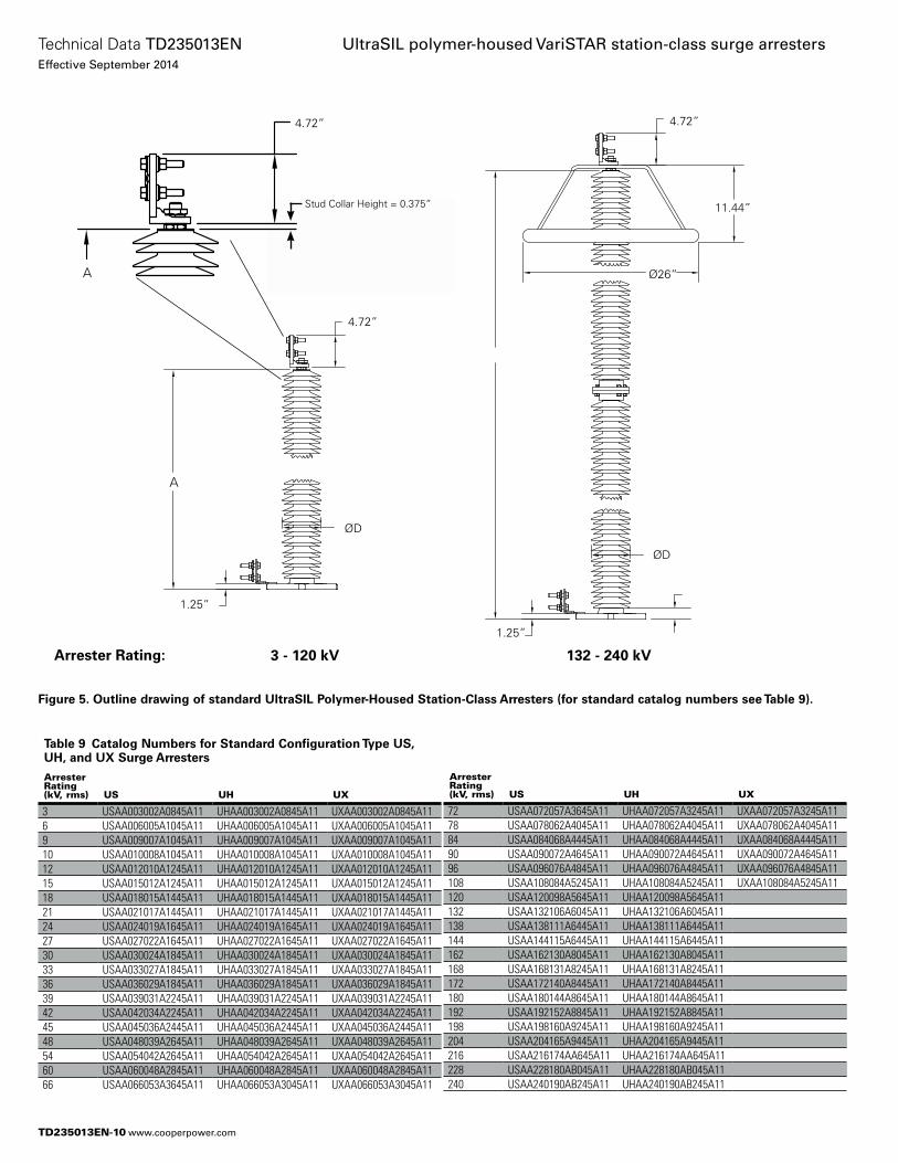
Figure 5. Outline drawing of standard UltraSIL Polymer-Housed Station-Class Arresters (for standard catalog numbers see Table 9).
4.72”
1.25”
1.25”
11.44”
132 - 240 kV3 - 120 kV
4.72”
Ø26”
ØD
ØD
Arrester Rating:
A
Table 9 Catalog Numbers for Standard Configuration Type US, UH, and UX Surge Arresters
Arrester Rating (kV, rms) US UH UX
3 USAA003002A0845A11 UHAA003002A0845A11 UXAA003002A0845A116 USAA006005A1045A11 UHAA006005A1045A11 UXAA006005A1045A119 USAA009007A1045A11 UHAA009007A1045A11 UXAA009007A1045A1110 USAA010008A1045A11 UHAA010008A1045A11 UXAA010008A1045A1112 USAA012010A1245A11 UHAA012010A1245A11 UXAA012010A1245A1115 USAA015012A1245A11 UHAA015012A1245A11 UXAA015012A1245A1118 USAA018015A1445A11 UHAA018015A1445A11 UXAA018015A1445A1121 USAA021017A1445A11 UHAA021017A1445A11 UXAA021017A1445A1124 USAA024019A1645A11 UHAA024019A1645A11 UXAA024019A1645A1127 USAA027022A1645A11 UHAA027022A1645A11 UXAA027022A1645A1130 USAA030024A1845A11 UHAA030024A1845A11 UXAA030024A1845A1133 USAA033027A1845A11 UHAA033027A1845A11 UXAA033027A1845A1136 USAA036029A1845A11 UHAA036029A1845A11 UXAA036029A1845A1139 USAA039031A2245A11 UHAA039031A2245A11 UXAA039031A2245A1142 USAA042034A2245A11 UHAA042034A2245A11 UXAA042034A2245A1145 USAA045036A2445A11 UHAA045036A2445A11 UXAA045036A2445A1148 USAA048039A2645A11 UHAA048039A2645A11 UXAA048039A2645A1154 USAA054042A2645A11 UHAA054042A2645A11 UXAA054042A2645A1160 USAA060048A2845A11 UHAA060048A2845A11 UXAA060048A2845A1166 USAA066053A3645A11 UHAA066053A3045A11 UXAA066053A3045A11
Arrester Rating (kV, rms) US UH UX
72 USAA072057A3645A11 UHAA072057A3245A11 UXAA072057A3245A1178 USAA078062A4045A11 UHAA078062A4045A11 UXAA078062A4045A1184 USAA084068A4445A11 UHAA084068A4445A11 UXAA084068A4445A1190 USAA090072A4645A11 UHAA090072A4645A11 UXAA090072A4645A1196 USAA096076A4845A11 UHAA096076A4845A11 UXAA096076A4845A11108 USAA108084A5245A11 UHAA108084A5245A11 UXAA108084A5245A11120 USAA120098A5645A11 UHAA120098A5645A11132 USAA132106A6045A11 UHAA132106A6045A11138 USAA138111A6445A11 UHAA138111A6445A11144 USAA144115A6445A11 UHAA144115A6445A11162 USAA162130A8045A11 UHAA162130A8045A11168 USAA168131A8245A11 UHAA168131A8245A11172 USAA172140A8445A11 UHAA172140A8445A11180 USAA180144A8645A11 UHAA180144A8645A11192 USAA192152A8845A11 UHAA192152A8845A11198 USAA198160A9245A11 UHAA198160A9245A11204 USAA204165A9445A11 UHAA204165A9445A11216 USAA216174AA645A11 UHAA216174AA645A11228 USAA228180AB045A11 UHAA228180AB045A11240 USAA240190AB245A11 UHAA240190AB245A11
Stud Collar Height = 0.375”
A
4.72”
TD235013EN-10
Technical Data TD235013ENEffective September 2014
UltraSIL polymer-housed VariSTAR station-class surge arresters
www.cooperpower.com
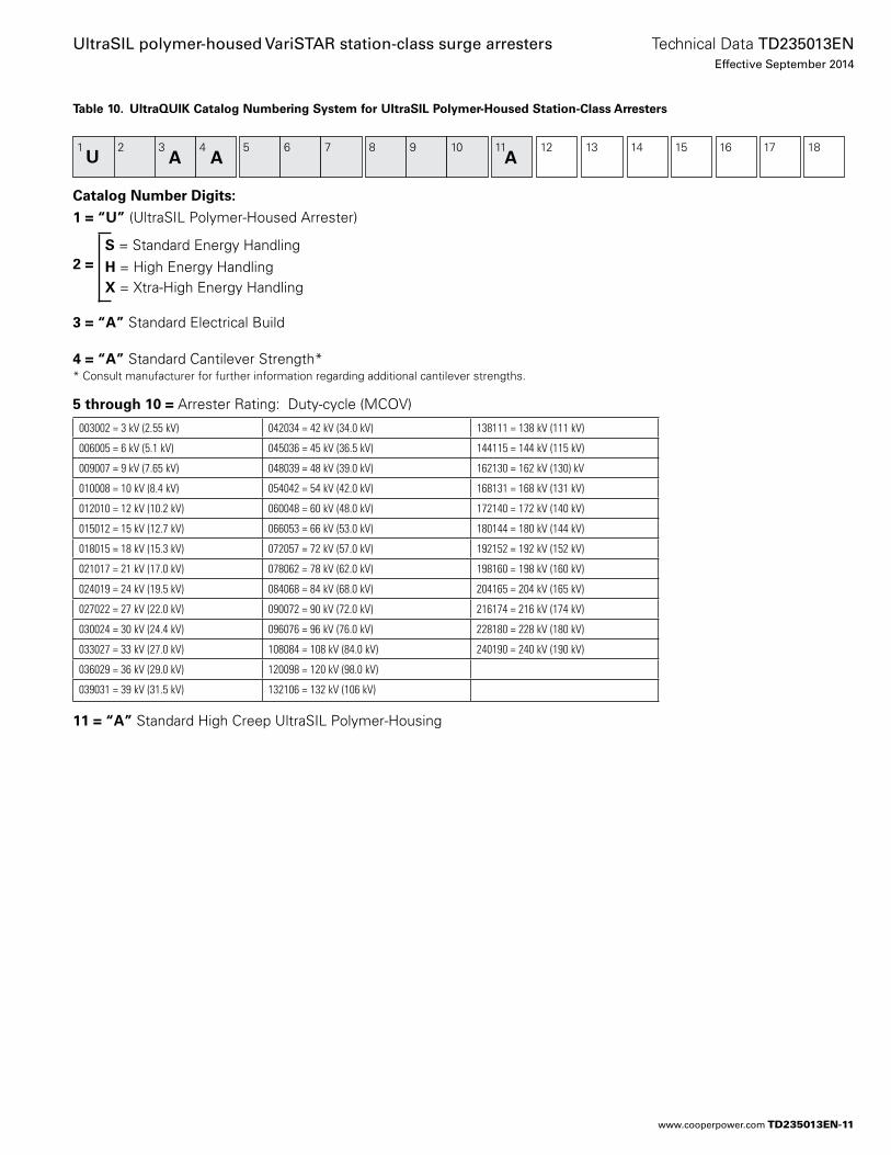
Table 10. UltraQUIK Catalog Numbering System for UltraSIL Polymer-Housed Station-Class Arresters
Catalog Number Digits:
1 = “U” (UltraSIL Polymer-Housed Arrester)
S = Standard Energy Handling 2 = H = High Energy Handling X = Xtra-High Energy Handling
3 = “A” Standard Electrical Build
4 = “A” Standard Cantilever Strength** Consult manufacturer for further information regarding additional cantilever strengths.
5 through 10 = Arrester Rating: Duty-cycle (MCOV)
11 = “A” Standard High Creep UltraSIL Polymer-Housing
1U
2 3 4 5 6 7 8 9 10 11 12 13 14 15 16 17 18A A A
003002 = 3 kV (2.55 kV) 042034 = 42 kV (34.0 kV) 138111 = 138 kV (111 kV)
006005 = 6 kV (5.1 kV) 045036 = 45 kV (36.5 kV) 144115 = 144 kV (115 kV)
009007 = 9 kV (7.65 kV) 048039 = 48 kV (39.0 kV) 162130 = 162 kV (130) kV
010008 = 10 kV (8.4 kV) 054042 = 54 kV (42.0 kV) 168131 = 168 kV (131 kV)
012010 = 12 kV (10.2 kV) 060048 = 60 kV (48.0 kV) 172140 = 172 kV (140 kV)
015012 = 15 kV (12.7 kV) 066053 = 66 kV (53.0 kV) 180144 = 180 kV (144 kV)
018015 = 18 kV (15.3 kV) 072057 = 72 kV (57.0 kV) 192152 = 192 kV (152 kV)
021017 = 21 kV (17.0 kV) 078062 = 78 kV (62.0 kV) 198160 = 198 kV (160 kV)
024019 = 24 kV (19.5 kV) 084068 = 84 kV (68.0 kV) 204165 = 204 kV (165 kV)
027022 = 27 kV (22.0 kV) 090072 = 90 kV (72.0 kV) 216174 = 216 kV (174 kV)
030024 = 30 kV (24.4 kV) 096076 = 96 kV (76.0 kV) 228180 = 228 kV (180 kV)
033027 = 33 kV (27.0 kV) 108084 = 108 kV (84.0 kV) 240190 = 240 kV (190 kV)
036029 = 36 kV (29.0 kV) 120098 = 120 kV (98.0 kV)
039031 = 39 kV (31.5 kV) 132106 = 132 kV (106 kV)
TD235013EN-11
Technical Data TD235013ENEffective September 2014
UltraSIL polymer-housed VariSTAR station-class surge arresters
www.cooperpower.com
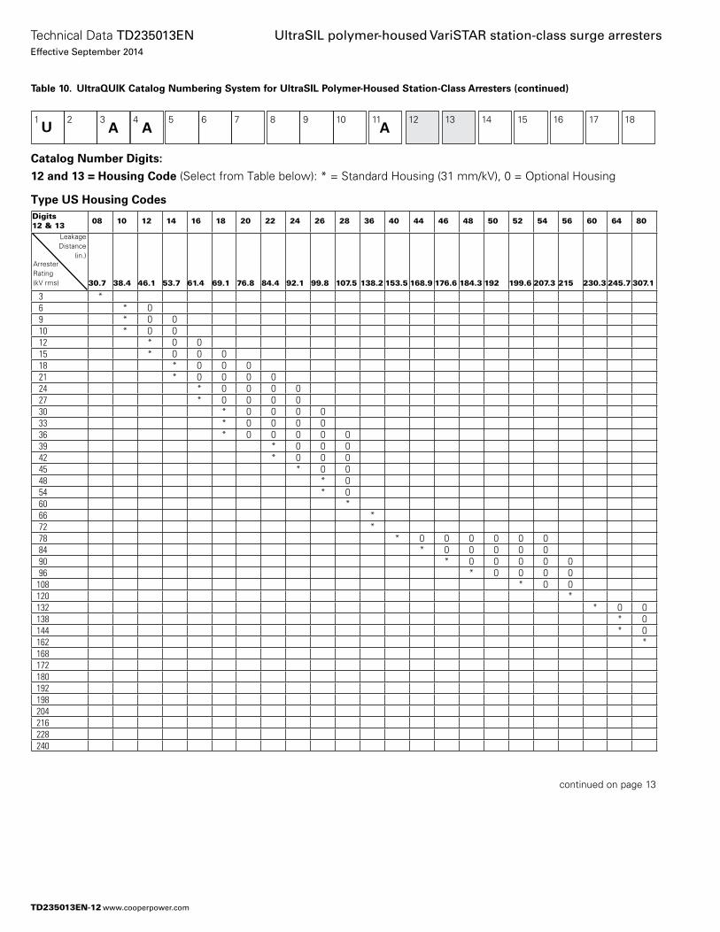
Table 10. UltraQUIK Catalog Numbering System for UltraSIL Polymer-Housed Station-Class Arresters (continued)
Catalog Number Digits:
12 and 13 = Housing Code (Select from Table below): * = Standard Housing (31 mm/kV), 0 = Optional Housing
Type US Housing Codes
1U
2 3 4 5 6 7 8 9 10 11 12 13 14 15 16 17 18A A A
Digits 12 & 13 08 10 12 14 16 18 20 22 24 26 28 36 40 44 46 48 50 52 54 56 60 64 80
30.7 38.4 46.1 53.7 61.4 69.1 76.8 84.4 92.1 99.8 107.5 138.2 153.5 168.9 176.6 184.3 192 199.6 207.3 215 230.3 245.7 307.1
3 * 6 * O 9 * O O 10 * O O 12 * O O 15 * O O O 18 * O O O 21 * O O O O 24 * O O O O 27 * O O O O 30 * O O O O 33 * O O O O 36 * O O O O O 39 * O O O 42 * O O O 45 * O O 48 * O 54 * O 60 * 66 * 72 * 78 * O O O O O O 84 * O O O O O 90 * O O O O O 96 * O O O O108 * O O120 *132 * O O138 * O144 * O162 *168172180192198204216228240
LeakageDistance
(in.)ArresterRating(kV rms)
continued on page 13
TD235013EN-12
Technical Data TD235013ENEffective September 2014
UltraSIL polymer-housed VariSTAR station-class surge arresters
www.cooperpower.com
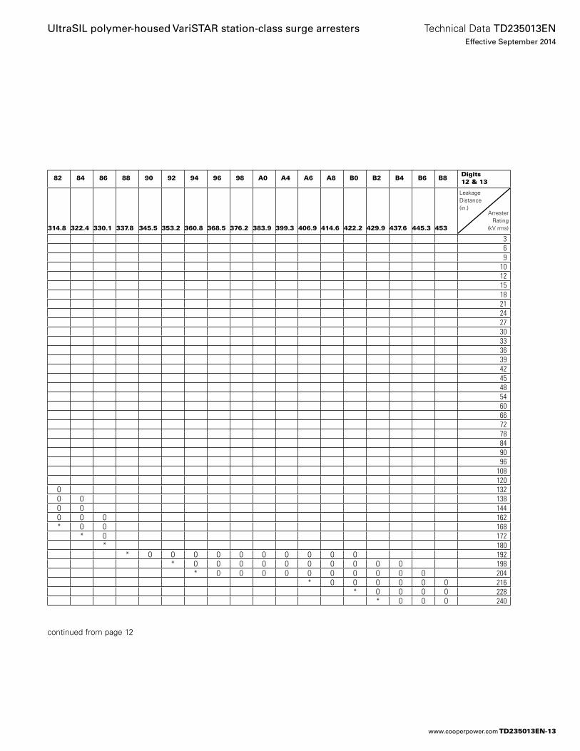
82 84 86 88 90 92 94 96 98 A0 A4 A6 A8 B0 B2 B4 B6 B8 Digits 12 & 13
314.8 322.4 330.1 337.8 345.5 353.2 360.8 368.5 376.2 383.9 399.3 406.9 414.6 422.2 429.9 437.6 445.3 453
3 6 9
10 12 15 18 21 24 27 30 33 36 39 42 45 48 54 60 66 72 78 84 90 96
108 120
O 132O O 138O O 144O O O 162* O O 168
* O 172* 180
* O O O O O O O O O O 192* O O O O O O O O O O 198
* O O O O O O O O O O 204* O O O O O O 216
* O O O O 228* O O O 240
LeakageDistance(in.)
ArresterRating
(kV rms)
continued from page 12
TD235013EN-13
Technical Data TD235013ENEffective September 2014
UltraSIL polymer-housed VariSTAR station-class surge arresters
www.cooperpower.com
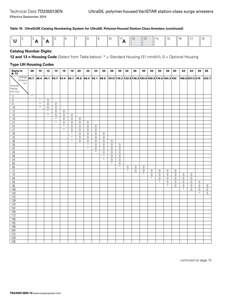
Table 10. UltraQUIK Catalog Numbering System for UltraSIL Polymer-Housed Station-Class Arresters (continued)
Catalog Number Digits:
12 and 13 = Housing Code (Select from Table below): * = Standard Housing (31 mm/kV), 0 = Optional Housing
Type UH Housing Codes
1U
2 3 4 5 6 7 8 9 10 11 12 13 14 15 16 17 18A A A
Digits12 & 13
08 10 12 14 16 18 20 22 24 26 28 30 32 36 40 44 46 48 50 52 54 56 58
30.7 38.4 46.1 53.7 61.4 69.1 76.8 84.4 92.1 99.8 107.5 115.2 122.8 138.2 153.5 168.9 176.6 184.3 192 199.6 207.3 215 222.7
3 * 6 * O 9 * O O 10 * O O 12 * O O 15 * O O O 18 * O O O 21 * O O O O 24 * O O O O 27 * O O O O 30 * O O O O 33 * O O O O 36 * O O O O O 39 * O O O O 42 * O O O O 45 * O O O 48 * O O 54 * O O 60 * O 66 * O O O 72 * O O O O O O 78 * O O O O O O 84 * O O O O O 90 * O O O O O 96 * O O O O O108 * O O O120 * O132138144162168172180192198204216228240
continued on page 15
LeakageDistance
(in.)ArresterRating(kV rms)
TD235013EN-14
Technical Data TD235013ENEffective September 2014
UltraSIL polymer-housed VariSTAR station-class surge arresters
www.cooperpower.com
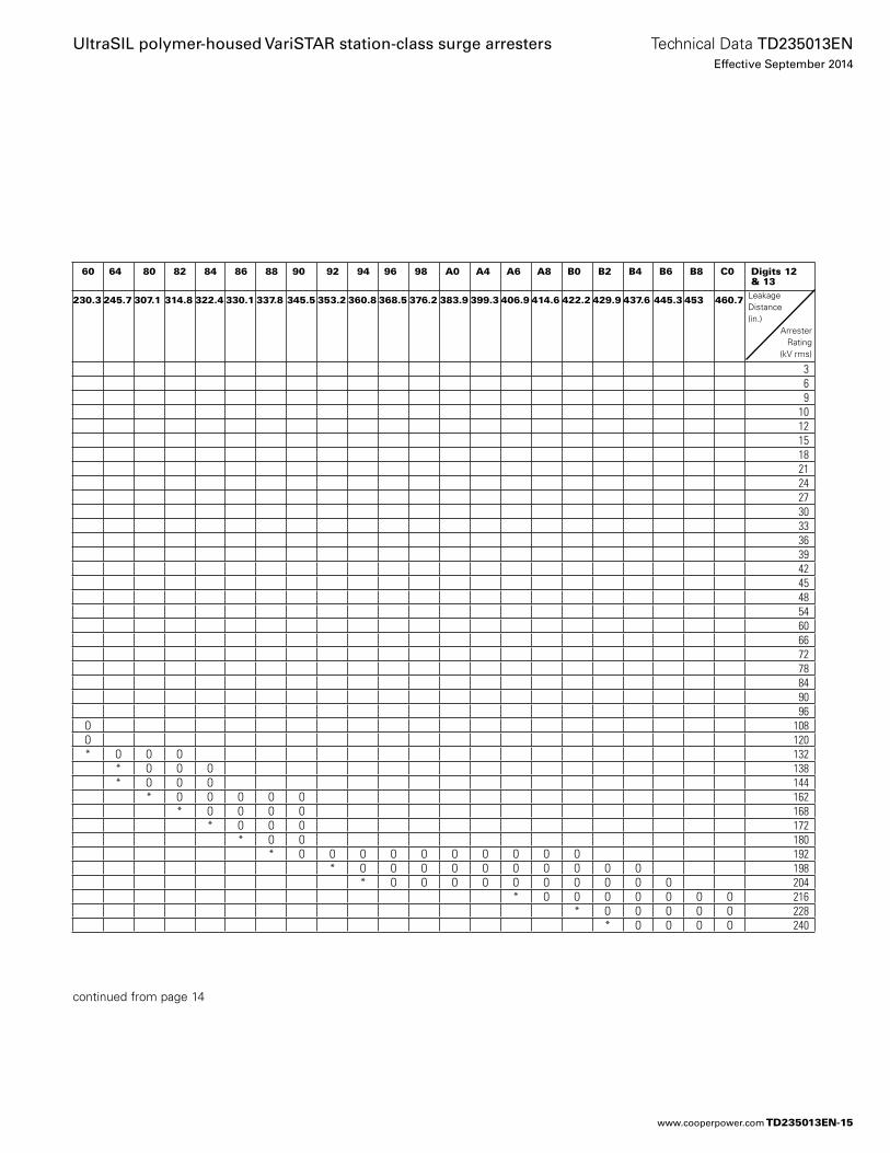
60 64 80 82 84 86 88 90 92 94 96 98 A0 A4 A6 A8 B0 B2 B4 B6 B8 C0 Digits 12 & 13
230.3 245.7 307.1 314.8 322.4 330.1 337.8 345.5 353.2 360.8 368.5 376.2 383.9 399.3 406.9 414.6 422.2 429.9 437.6 445.3 453 460.7
3 6 9
10 12 15 18 21 24 27 30 33 36 39 42 45 48 54 60 66 72 78 84 90 96
O 108 O 120 * O O O 132
* O O O 138* O O O 144
* O O O O O 162* O O O O 168
* O O O 172* O O 180
* O O O O O O O O O O 192* O O O O O O O O O O 198
* O O O O O O O O O O 204* O O O O O O O 216
* O O O O O 228* O O O O 240
continued from page 14
LeakageDistance(in.)
ArresterRating
(kV rms)
TD235013EN-15
Technical Data TD235013ENEffective September 2014
UltraSIL polymer-housed VariSTAR station-class surge arresters
www.cooperpower.com
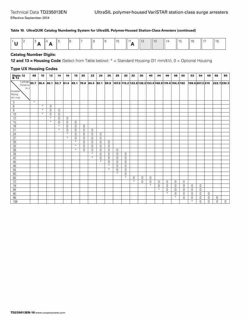
Table 10. UltraQUIK Catalog Numbering System for UltraSIL Polymer-Housed Station-Class Arresters (continued)
Catalog Number Digits:
12 and 13 = Housing Code (Select from Table below): * = Standard Housing (31 mm/kV), 0 = Optional Housing
Type UX Housing Codes
1U
2 3 4 5 6 7 8 9 10 11 12 13 14 15 16 17 18A A A
Digits 12 & 13
08 10 12 14 16 18 20 22 24 26 28 30 32 36 40 44 46 48 50 52 54 56 58 60
30.7 38.4 46.1 53.7 61.4 69.1 76.8 84.4 92.1 99.8 107.5 115.2 122.8 138.2 153.5 168.9 176.6 184.3 192 199.6 207.3 215 222.7230.3
3 * 6 * O 9 * O O 10 * O O 12 * O O 15 * O O O 18 * O O O 21 * O O O O 24 * O O O O 27 * O O O O 30 * O O O O 33 * O O O O 36 * O O O O O 39 * O O O O 42 * O O O O 45 * O O O 48 * O O 54 * O O 60 * O 66 * O O O 72 * O O O O O O 78 * O O O O O O 84 * O O O O O 90 * O O O O O 96 * O O O O O 108 * O O O O
LeakageDistance
(in.)ArresterRating(kV rms)
TD235013EN-16
Technical Data TD235013ENEffective September 2014
UltraSIL polymer-housed VariSTAR station-class surge arresters
www.cooperpower.com
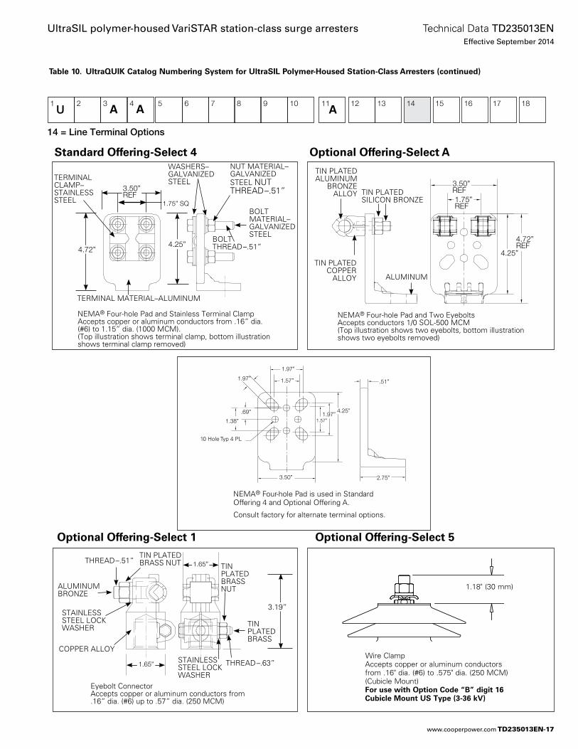
14 = Line Terminal Options
TIN PLATED SILICON BRONZE
ALUMINUM
TIN PLATED COPPER
ALLOY
TIN PLATED ALUMINUM
BRONZE ALLOY
3.50”REF1.75”REF
4.72”REF
4.25”
NEMA® Four-hole Pad and Two EyeboltsAccepts conductors 1/0 SOL-500 MCM(Top illustration shows two eyebolts, bottom illustration shows two eyebolts removed)
Table 10. UltraQUIK Catalog Numbering System for UltraSIL Polymer-Housed Station-Class Arresters (continued)
1U
2 3 4 5 6 7 8 9 10 11 12 13 14 15 16 17 18
1.75” SQ
4.72”4.25”
3.50”REF
BOLT THREAD–.51”
NUT MATERIAL–GALVANIZED STEEL NUT THREAD–.51”
WASHERS–GALVANIZED STEEL
TERMINAL MATERIAL–ALUMINUM
TERMINAL CLAMP–STAINLESS STEEL
BOLT MATERIAL–GALVANIZED STEEL
NEMA® Four-hole Pad and Stainless Terminal ClampAccepts copper or aluminum conductors from .16” dia. (#6) to 1.15” dia. (1000 MCM).(Top illustration shows terminal clamp, bottom illustration shows terminal clamp removed)
Standard Offering-Select 4
Eyebolt Connector Accepts copper or aluminum conductors from .16” dia. (#6) up to .57” dia. (250 MCM)
STAINLESS STEEL LOCK WASHER
ALUMINUM BRONZE
COPPER ALLOY
THREAD–.51”TIN PLATED BRASS NUT TIN
PLATED BRASS NUT
THREAD–.63”
TIN PLATED BRASS
STAINLESS STEEL LOCK WASHER
1.65”
1.65”
3.19”
Optional Offering-Select 1 Optional Offering-Select 5
A A A
Optional Offering-Select A
NEMA® Four-hole Pad is used in Standard Offering 4 and Optional Offering A.
Consult factory for alternate terminal options.
1.97”
1.57”1.97”
4.25” 1.97”
1.57”
.69”
1.38”
3.50”
10 Hole Typ 4 PL
.51”
2.75”
Wire Clamp Accepts copper or aluminum conductors from .16" dia. (#6) to .575" dia. (250 MCM) (Cubicle Mount)
For use with Option Code “B” digit 16 Cubicle Mount US Type (3-36 kV)
1.18" (30 mm)
TD235013EN-17
Technical Data TD235013ENEffective September 2014
UltraSIL polymer-housed VariSTAR station-class surge arresters
www.cooperpower.com
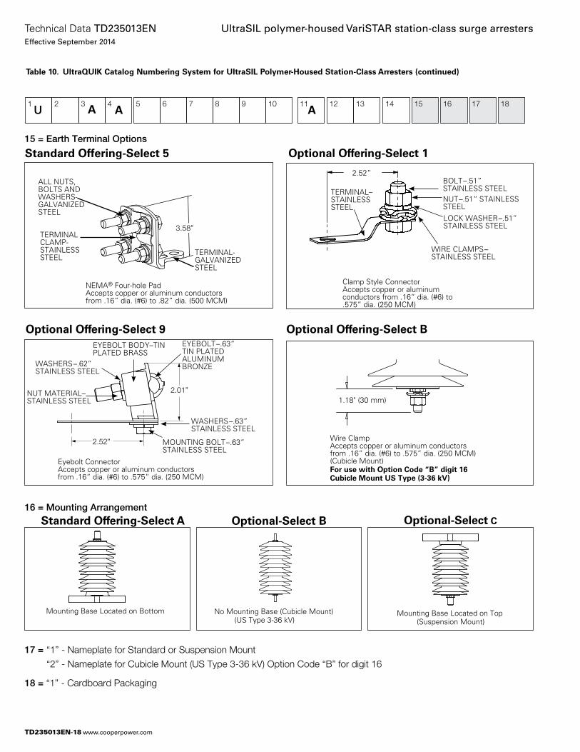
Mounting Base Located on Bottom Mounting Base Located on Top (Suspension Mount)
No Mounting Base (Cubicle Mount) (US Type 3-36 kV)
15 = Earth Terminal Options
16 = Mounting Arrangement
17 = “1” - Nameplate for Standard or Suspension Mount
“2” - Nameplate for Cubicle Mount (US Type 3-36 kV) Option Code “B” for digit 16
18 = “1” - Cardboard Packaging
2.52”
2.01”
Eyebolt Connector Accepts copper or aluminum conductors from .16” dia. (#6) to .575” dia. (250 MCM)
EYEBOLT BODY–TIN PLATED BRASS
EYEBOLT–.63” TIN PLATED ALUMINUM BRONZE
MOUNTING BOLT–.63” STAINLESS STEEL
WASHERS–.62” STAINLESS STEEL
NUT MATERIAL–STAINLESS STEEL
WASHERS–.63” STAINLESS STEEL
1U
2 3 4 5 6 7 8 9 10 11 12 13 14 15 16 17 18
Table 10. UltraQUIK Catalog Numbering System for UltraSIL Polymer-Housed Station-Class Arresters (continued)
120 mm
91 mm
NEMA® Four-hole Pad Accepts copper or aluminum conductors from .16” dia. (#6) to .82” dia. (500 MCM)
3.58”
TERMINAL-GALVANIZED STEEL
ALL NUTS, BOLTS AND WASHERS-GALVANIZED STEEL
TERMINAL CLAMP-STAINLESS STEEL
Standard Offering-Select 5
2.52”
Clamp Style ConnectorAccepts copper or aluminum conductors from .16” dia. (#6) to .575” dia. (250 MCM)
TERMINAL–STAINLESS STEEL
WIRE CLAMPS–STAINLESS STEEL
BOLT–.51” STAINLESS STEELNUT–.51” STAINLESS STEELLOCK WASHER–.51” STAINLESS STEEL
Optional Offering-Select 1
Optional Offering-Select 9 Optional Offering-Select B
Standard Offering-Select A Optional-Select COptional-Select B
A A A
1.18" (30 mm)
Wire ClampAccepts copper or aluminum conductors from .16” dia. (#6) to .575” dia. (250 MCM) (Cubicle Mount)For use with Option Code “B” digit 16 Cubicle Mount US Type (3-36 kV)
TD235013EN-18
Technical Data TD235013ENEffective September 2014
UltraSIL polymer-housed VariSTAR station-class surge arresters
www.cooperpower.com
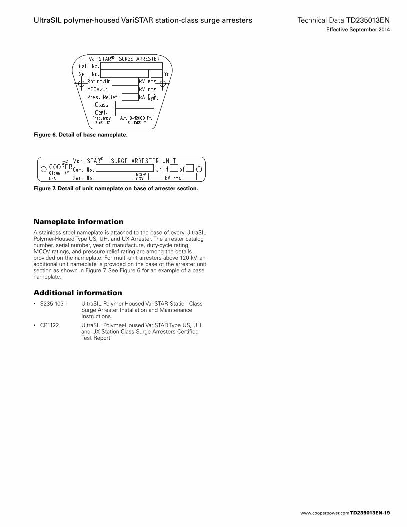
Figure 6. Detail of base nameplate.
Figure 7. Detail of unit nameplate on base of arrester section.
Nameplate informationA stainless steel nameplate is at tached to the base of every UltraSIL Polymer-Housed Type US, UH, and UX Arrester. The arrester catalog number, serial number, year of manufacture, duty-cycle rating, MCOV ratings, and pressure relief rating are among the details provided on the nameplate. For multi-unit arresters above 120 kV, an additional unit nameplate is provided on the base of the arrester unit section as shown in Figure 7. See Figure 6 for an example of a base nameplate.
Additional information• S235-103-1 UltraSIL Polymer-Housed VariSTAR Station-Class
Surge Arrester Installation and Maintenance Instructions.
• CP1122 UltraSIL Polymer-Housed VariSTAR Type US, UH, and UX Station-Class Surge Arresters Certified Test Report.
TD235013EN-19
Technical Data TD235013ENEffective September 2014
UltraSIL polymer-housed VariSTAR station-class surge arresters
www.cooperpower.com
UltraSIL polymer-housed VariSTAR station-class surge arrestersTechnical Data TD235013ENEffective September 2014
Eaton, Cooper Power Systems, VariSTAR and UltraSIL are valuable trademarks of Eaton in the U.S. and other countries. You are not permitted to use these trademarks without the prior written consent of Eaton.IEEE is a registered trademark of the Institute of Electrical and Electronics Engineers, Inc.IEEE Std C62.11™-2005, IEEE Std C62.22™-2009 and IEEE Std 62.11a™-2008 standards are trademarks of the Institute of Electrical and Electronics Engineers, Inc., (IEEE). This publication/product is not endorsed or approved by the IEEE.
Eaton1000 Eaton BoulevardCleveland, OH 44122United StatesEaton.com
Eaton’s Cooper Power Systems Business2300 Badger DriveWaukesha, WI 53188United StatesCooperpower.com
© 2014 EatonAll Rights ReservedPrinted in USAPublication No. TD235013EN
For Eaton’s Cooper Power Systems VariSTAR station-class surge arrester product information call 1-877-277-4636 or visit: www.cooperpower.com.
TD235013EN-20
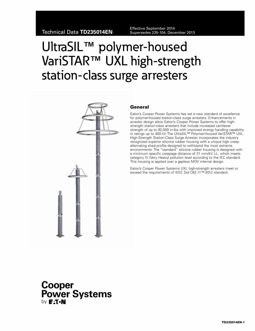
UltraSIL™ polymer-housed VariSTAR™ UXL high-strength station-class surge arresters
GeneralEaton’s Cooper Power Systems has set a new standard of excellence for polymer-housed station-class surge arresters. Enhancements in arrester design allow Eaton’s Cooper Power Systems to offer high-strength station-class arresters that include increased cantilever strength of up to 92,000 in-lbs with improved energy handling capability in ratings up to 400 kV. The UltraSIL™ Polymer-Housed VariSTAR™ UXL High-Strength Station-Class Surge Arrester incorporates the industry recognized superior silicone rubber housing with a unique high creep alternating shed profile designed to withstand the most extreme environments. The “standard” silicone rubber housing is designed with a minimum specific creepage distance of 31 mm/kV L-L, which meets category IV (Very Heavy) pollution level according to the IEC standard. This housing is applied over a gapless MOV internal design.
Eaton’s Cooper Power Systems UXL high-strength arresters meet or exceed the requirements of IEEE Std C62.11™-2012 standard.
Technical Data TD235014ENEffective September 2014Supersedes 235-104, December 2013
TD235014EN-1
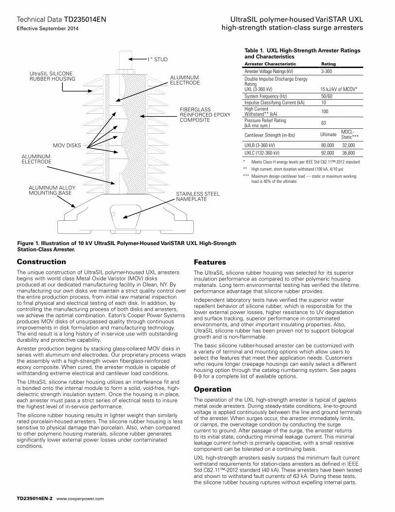
ConstructionThe unique construction of UltraSIL polymer-housed UXL arresters begins with world class Metal Oxide Varistor (MOV) disks produced at our dedicated manufacturing facility in Olean, NY. By manufacturing our own disks we maintain a strict quality control over the entire pro duction process, from initial raw material inspection to final physical and electrical testing of each disk. In addition, by controlling the manufacturing process of both disks and arresters, we achieve the optimal combination. Eaton’s Cooper Power Systems produces MOV disks of unsurpassed quality through continuous improvements in disk formulation and manufacturing technology. The end result is a long history of in-service use with outstanding durability and protective capability.
Arrester production begins by stacking glass-collared MOV disks in series with aluminum end electrodes. Our proprietary process wraps the assembly with a high-strength woven fiberglass-reinforced epoxy composite. When cured, the arrester module is capable of withstanding extreme electrical and cantilever load conditions.
The UltraSIL silicone rubber housing utilizes an inter ference fit and is bonded onto the internal module to form a solid, void-free, high-dielectric strength insulation system. Once the housing is in place, each arrester must pass a strict series of electrical tests to insure the highest level of in-service performance.
The silicone rubber housing results in lighter weight than similarly rated porcelain-housed arresters. The silicone rubber housing is less sensitive to physical damage than porcelain. Also, when compared to other polymeric housing materials, silicone rubber generates significantly lower external power losses under contaminated conditions.
FeaturesThe UltraSIL silicone rubber housing was selected for its superior insula tion performance as compared to other polymeric housing materials. Long term environmental testing has verified the lifetime performance advantage that silicone rubber provides.
Independent laboratory tests have verified the superior water repellent behavior of silicone rubber, which is responsible for the lower external power losses, higher resistance to UV degradation and surface tracking, superior performance in contaminated environments, and other important insulating properties. Also, UltraSIL silicone rubber has been proven not to support biological growth and is non-flammable.
The basic silicone rubber-housed arrester can be customized with a variety of terminal and mounting options which allow users to select the features that meet their application needs. Customers who require longer creepage housings can easily select a different housing option through the catalog numbering system. See pages 8-9 for a complete list of available options.
OperationThe operation of the UXL high-strength arrester is typical of gapless metal oxide arresters. During steady-state conditions, line-to-ground voltage is applied con tinuously between the line and ground terminals of the arrester. When surges occur, the arrester immediately limits, or clamps, the overvoltage condition by conducting the surge current to ground. After passage of the surge, the arrester returns to its initial state, conducting minimal leakage current. This minimal leakage current (which is primarily capacitive, with a small resistive component) can be tolerated on a continuing basis.
UXL high-strength arresters easily surpass the minimum fault current withstand requirements for station-class arresters as defined in IEEE Std C62.11™-2012 standard (40 kA). These arresters have been tested and shown to withstand fault currents of 63 kA. During these tests, the silicone rubber housing ruptures without expelling internal parts.
Figure 1. Illustration of 10 kV UltraSIL Polymer-Housed VariSTAR UXL High-Strength Station-Class Arrester.
UltraSIL SILICONE RUBBER HOUSING
STAINLESS STEEL NAMEPLATE
ALUMINUM ALLOY MOUNTING BASE
FIBERGLASS REINFORCED EPOXY COMPOSITE
MOV DISKS
ALUMINUM ELECTRODE
ALUMINUM ELECTRODE
* Meets Class H energy levels per IEEE Std C62.11™-2012 standard
** High current, short duration withstand (100 kA, 4/10 µs)
*** Maximum design cantilever load — static or maximum working load is 40% of the ultimate.
Table 1. UXL High-Strength Arrester Ratings and CharacteristicsArrester Characteristic Rating
Arrester Voltage Ratings (kV) 3-360Double Impulse Discharge Energy RatingUXL (3-360 kV) 15 kJ/kV of MCOV*System Frequency (Hz) 50/60Impulse Classifying Current (kA) 10High Current Withstand** (kA) 100
Pressure Relief Rating (kA rms sym.) 63
Cantilever Strength (in-Ibs) Ultimate MDCL-Static***
UXLB (3-360 kV) 80,000 32,000UXLC (132-360 kV) 92,000 36,800
1” STUD
TD235014EN-2
Technical Data TD235014ENEffective September 2014
UltraSIL polymer-housed VariSTAR UXL high-strength station-class surge arresters
www.cooperpower.com
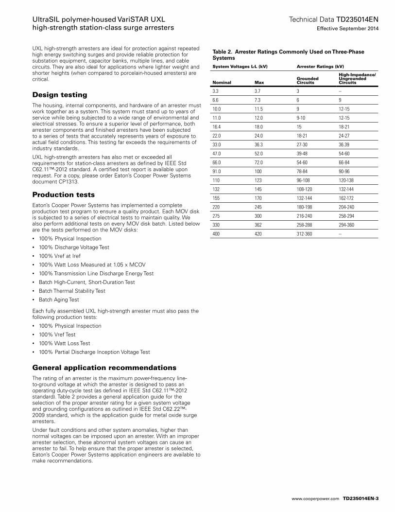
UXL high-strength arresters are ideal for protection against repeated high energy switching surges and provide reliable protection for substation equipment, capacitor banks, multiple lines, and cable circuits. They are also ideal for applications where lighter weight and shorter heights (when compared to porcelain-housed arresters) are critical.
Design testingThe housing, internal components, and hardware of an arrester must work together as a system. This system must stand up to years of service while being subjected to a wide range of environmental and electrical stresses. To ensure a superior level of performance, both arrester components and finished arresters have been subjected to a series of tests that accurately represents years of exposure to actual field conditions. This testing far exceeds the requirements of industry standards.
UXL high-strength arresters has also met or exceeded all requirements for station-class arresters as defined by IEEE Std C62.11™-2012 standard. A certified test report is available upon request. For a copy, please order Eaton’s Cooper Power Systems document CP1313.
Production testsEaton’s Cooper Power Systems has implemented a complete production test program to ensure a quality product. Each MOV disk is subjected to a series of electrical tests to maintain quality. We also perform additional tests on every MOV disk batch. Listed below are the tests performed on the MOV disks:• 100% Physical Inspection• 100% Discharge Voltage Test• 100% Vref at Iref• 100% Watt Loss Measured at 1.05 x MCOV• 100% Transmission Line Discharge Energy Test• Batch High-Current, Short-Duration Test• Batch Thermal Stability Test• Batch Aging Test
Each fully assembled UXL high-strength arrester must also pass the following production tests:• 100% Physical Inspection• 100% Vref Test• 100% Watt Loss Test• 100% Partial Discharge Inception Voltage Test
General application recommendationsThe rating of an arrester is the maximum power-frequency line-to-ground voltage at which the arrester is designed to pass an operating duty-cycle test (as defined in IEEE Std C62.11™-2012 standard). Table 2 provides a general application guide for the selection of the proper arrester rating for a given system voltage and grounding configurations as outlined in IEEE Std C62.22™-2009 standard, which is the application guide for metal oxide surge arresters.
Under fault conditions and other system anomalies, higher than normal voltages can be imposed upon an arrester. With an improper arrester selection, these abnormal system voltages can cause an arrester to fail. To help ensure that the proper arrester is selected, Eaton’s Cooper Power Systems application engineers are available to make recommendations.
Table 2. Arrester Ratings Commonly Used on Three-Phase Systems
System Voltages L-L (kV) Arrester Ratings (kV)
Nominal MaxGroundedCircuits
High-Impedance/Ungrounded Circuits
3.3 3.7 3 –
6.6 7.3 6 9
10.0 11.5 9 12-15
11.0 12.0 9-10 12-15
16.4 18.0 15 18-21
22.0 24.0 18-21 24-27
33.0 36.3 27-30 36.39
47.0 52.0 39-48 54-60
66.0 72.0 54-60 66-84
91.0 100 78-84 90-96
110 123 96-108 120-138
132 145 108-120 132-144
155 170 132-144 162-172
220 245 180-198 204-240
275 300 216-240 258-294
330 362 258-288 294-360
400 420 312-360 –
TD235014EN-3
Technical Data TD235014ENEffective September 2014
UltraSIL polymer-housed VariSTAR UXL high-strength station-class surge arresters
www.cooperpower.com
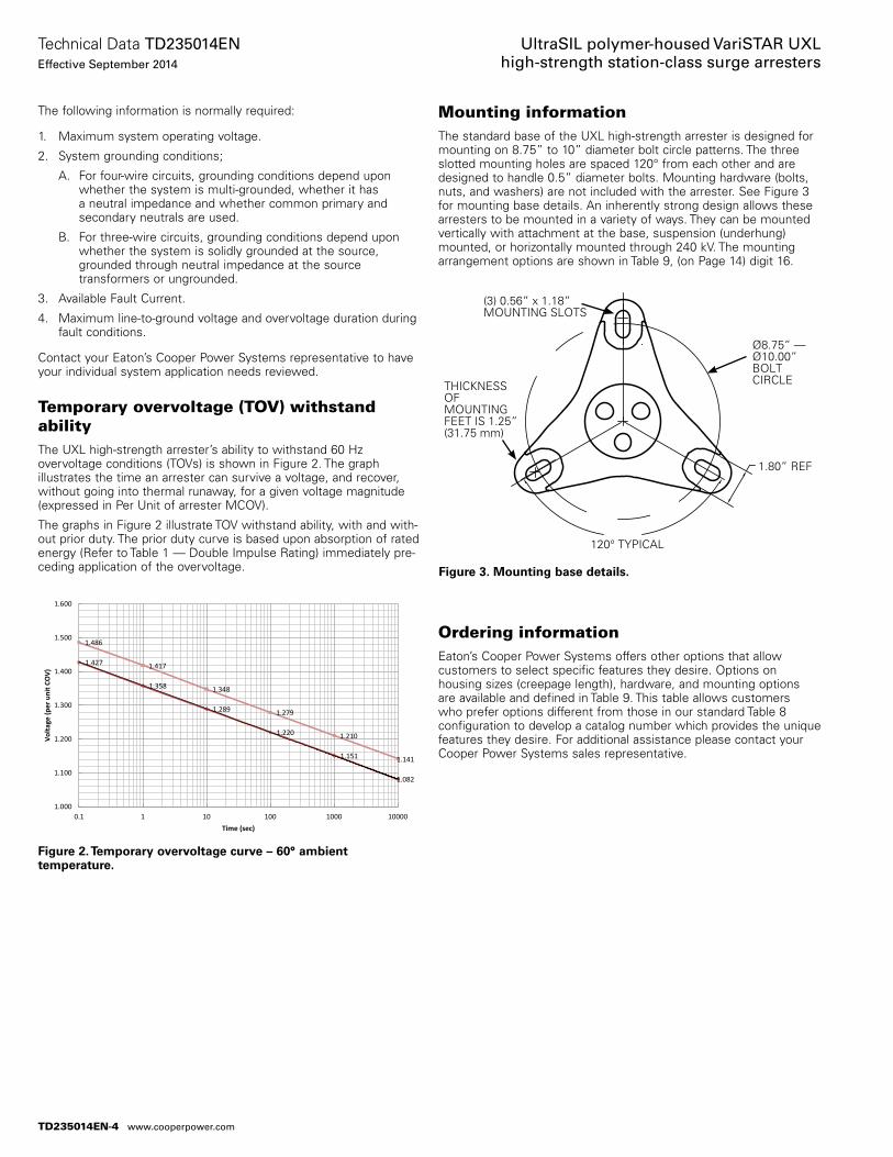
The following information is normally required:
1. Maximum system operating voltage.
2. System grounding conditions;
A. For four-wire circuits, grounding conditions depend upon whether the system is multi-grounded, whether it has a neutral impedance and whether common primary and secondary neutrals are used.
B. For three-wire circuits, grounding conditions depend upon whether the system is solidly grounded at the source, grounded through neutral impedance at the source transformers or ungrounded.
3. Available Fault Current.
4. Maximum line-to-ground voltage and overvoltage duration during fault conditions.
Contact your Eaton’s Cooper Power Systems representative to have your individual system application needs reviewed.
Temporary overvoltage (TOV) withstand abilityThe UXL high-strength arrester’s ability to withstand 60 Hz overvoltage conditions (TOVs) is shown in Figure 2. The graph illustrates the time an arrester can survive a voltage, and recover, without going into thermal runaway, for a given voltage magnitude (expressed in Per Unit of arrester MCOV).
The graphs in Figure 2 illustrate TOV withstand ability, with and with-out prior duty. The prior duty curve is based upon absorption of rated energy (Refer to Table 1 — Double Impulse Rating) immediately pre-ceding application of the overvoltage.
Mounting informationThe standard base of the UXL high-strength arrester is designed for mounting on 8.75” to 10” diameter bolt circle patterns. The three slotted mounting holes are spaced 120° from each other and are designed to handle 0.5” diameter bolts. Mounting hardware (bolts, nuts, and washers) are not in cluded with the arrester. See Figure 3 for mounting base details. An inherently strong design allows these arresters to be mounted in a variety of ways. They can be mounted vertically with attachment at the base, suspension (underhung) mounted, or horizontally mounted through 240 kV. The mounting arrangement options are shown in Table 9, (on Page 14) digit 16.
Ordering informationEaton’s Cooper Power Systems offers other options that allow customers to select specific features they desire. Options on housing sizes (creepage length), hardware, and mounting options are available and defined in Table 9. This table allows customers who prefer options different from those in our standard Table 8 configuration to develop a catalog number which provides the unique features they desire. For additional assistance please contact your Cooper Power Systems sales representative.
Figure 3. Mounting base details.
(3) 0.56” x 1.18” MOUNTING SLOTS
THICKNESS OF MOUNTING FEET IS 1.25” (31.75 mm)
Ø8.75” — Ø10.00” BOLT CIRCLE
120° TYPICAL
1.80” REF
Figure 2. Temporary overvoltage curve – 60° ambient temperature.
1.486
1.417
1.348
1.279
1.210
1.141
1.427
1.358
1.289
1.220
1.151
1.082
1.000
1.100
1.200
1.300
1.400
1.500
1.600
0.1 1 10 100 1000 10000
Volta
ge (p
er u
nit C
OV)
Time (sec)
TD235014EN-4
Technical Data TD235014ENEffective September 2014
UltraSIL polymer-housed VariSTAR UXL high-strength station-class surge arresters
www.cooperpower.com
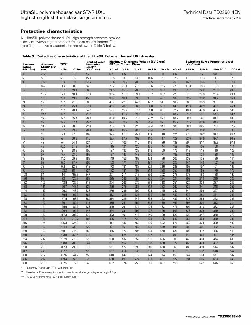
Protective characteristicsAll UltraSIL polymer-housed UXL high-strength arresters provide excellent overvoltage protection for electrical equipment. The specific protective characteristics are shown in Table 3 below.
* Temporary Overvoltage (TOV) with Prior Duty.
** Based on a 10 kA current impulse that results in a discharge voltage cresting in 0.5 µs.
*** 45-60 µs rise time for a 500 A peak current surge.
Table 3. Protective Characteristics of the UltraSIL Polymer-Housed UXL Arrester
Arrester Rating (kV, rms)
Arrester MCOV (kV rms)
TOV*Front-of-wave Protective Level** (kV Crest)
Maximum Discharge Voltage (kV Crest)8/20 µs Current Wave
Switching Surge Protective Level(kV Crest)
1 Sec 10 Sec 1.5 kA 3 kA 5 kA 10 kA 20 kA 40 kA 125 A 250 A 500 A*** 1000 A
3 2.55 3.5 3.3 7.7 6.2 6.5 6.8 7.3 7.8 8.6 5.5 5.7 5.8 66 5.1 6.9 6.6 15.3 12.5 13 13.5 14.6 15.6 17.2 11 11.3 11.6 129 7.65 10.4 9.9 22.5 18.4 19.2 20 21.5 23 25.3 16.2 16.6 17.1 17.710 8.4 11.4 10.8 24.7 20.2 21.1 21.9 23.6 25.2 27.8 17.8 18.3 18.8 19.512 10.2 13.9 13.1 30 24.5 25.6 26.6 28.7 30.6 33.8 21.7 22.2 22.8 23.615 12.7 17.2 16.4 37.3 30.4 31.9 33.1 35.7 38.1 42 27 27.6 28.4 29.418 15.3 20.8 19.7 45 36.7 38.4 39.9 43 45.9 50.6 32.4 33.2 34.2 35.421 17 23.1 21.9 50 40.7 42.6 44.3 47.7 51 56.2 36 36.9 38 39.324 19.5 26.5 25.1 57.3 46.7 48.9 50.8 54.8 58.5 64.5 41.3 42.3 43.6 45.127 22 29.9 28.4 64.7 52.7 55.2 57.3 61.8 66 72.7 46.6 47.8 49.2 50.930 24.4 33.1 31.5 71.7 58.4 61.2 63.6 68.5 73.2 80.7 51.7 53 54.5 56.433 27.5 37.3 35.4 80.8 65.8 68.9 71.6 77.2 82.5 90.9 58.3 59.7 61.4 63.636 29 39.4 37.4 85.2 69.4 72.7 75.5 81.4 87 95.9 61.5 62.9 64.8 67.139 31.5 42.8 40.6 92.6 75.4 79 82 88.4 94.5 105 66.8 68.4 70.4 72.942 34 46.2 43.8 99.9 81.4 85.2 88.6 95.4 102 113 72 73.8 76 78.645 36.5 49.6 47 108 87.4 91.5 95.1 103 110 121 77.4 79.2 81.6 84.448 39 53 50.3 115 93.4 97.7 102 110 117 129 82.6 84.6 87.1 90.254 42 57 54.1 124 101 106 110 118 126 139 89 91.1 93.8 97.160 48 65.2 61.9 141 115 121 125 135 144 159 102 105 108 11166 53 72 68.3 156 127 133 138 149 159 176 113 115 119 12372 57 77.4 73.5 168 137 143 149 160 171 189 121 124 128 13278 62 84.2 79.9 183 149 156 162 174 186 205 132 135 139 14484 68 92.3 87.7 200 163 171 178 191 204 225 144 148 152 15890 72 97.8 92.8 212 173 181 188 202 216 238 153 157 161 16796 76 103.2 98 224 182 191 198 214 228 252 161 165 170 176108 84 114.1 108.3 247 201 211 219 236 252 278 178 183 188 195120 98 133.1 126.3 288 235 246 256 275 294 324 208 213 219 227132 106 143.9 136.6 312 254 266 276 298 318 351 225 230 237 246138 111 150.7 143.1 326 266 279 289 312 333 367 236 241 248 257144 115 156.2 148.2 338 276 289 300 323 345 380 244 250 257 266162 130 176.5 167.6 382 312 326 339 365 390 430 276 282 291 301168 131 177.9 168.9 385 314 329 342 368 393 433 278 285 293 303172 140 190.1 180.5 412 335 351 365 393 420 463 297 304 313 324180 144 195.6 185.6 423 345 361 375 404 432 476 305 313 322 333192 152 206.4 195.9 447 364 381 396 427 456 503 322 330 340 352198 160 217.3 206.2 470 383 401 417 449 480 529 339 347 358 370204 165 224.1 212.7 485 395 414 430 463 495 546 350 358 369 382216 174 236.3 224.3 512 417 436 453 489 522 575 369 378 389 403228 180 244.4 232 529 431 451 469 505 540 595 382 391 402 417240 190 258 244.9 558 455 476 495 533 570 628 403 412 425 440258 209 283.8 269.4 614 501 524 545 587 627 691 443 454 467 484264 212 287.9 273.3 623 508 532 552 595 636 701 449 460 474 490276 220 298.8 283.6 647 527 552 573 618 660 727 466 478 492 509288 230 312.3 296.5 676 551 577 599 646 690 760 488 499 514 532312 245 332.7 315.8 720 587 614 638 688 735 810 519 532 548 567330 267 362.6 344.2 758 618 647 672 724 774 853 547 560 577 597336 272 369.4 350.6 820 668 699 727 783 837 922 591 605 623 645360 289 392.5 372.5 849 692 724 753 811 867 955 613 627 646 668
TD235014EN-5
Technical Data TD235014ENEffective September 2014
UltraSIL polymer-housed VariSTAR UXL high-strength station-class surge arresters
www.cooperpower.com
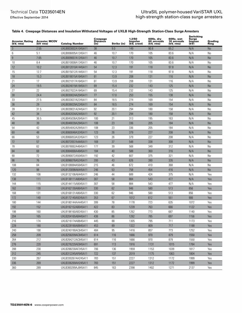
Table 4. Creepage Distances and Insulation Withstand Voltages of UXLB High-Strength Station-Class Surge Arresters
Arrester Rating (kV, rms)
Arrester MCOV (kV rms) Catalog Number
Creepage Distance (in) Strike (in)
1.2/50 Impulse (kV, crest)
60Hz, dry 60 seconds (kV, rms)
60Hz, wet 10 seconds (kV, rms)
Switching Surge Impuse (kV)
Grading Ring
3 2.55 UXLB003002A1045A11 38 9.0 149 90.8 65.2 N/A No6 5.1 UXLB006005A1245A11 46 10.7 170 105 83.6 N/A No9 7.65 UXLB009007A1245A11 46 10.7 170 105 83.6 N/A No10 8.4 UXLB010008A1245A11 46 10.7 170 105 83.6 N/A No12 10.2 UXLB012010A1445A11 54 12.3 191 118 97.8 N/A No15 12.7 UXLB015012A1445A11 54 12.3 191 118 97.8 N/A No18 15.3 UXLB018015A1645A11 61 13.9 208 131 116 N/A No21 17 UXLB021017A1645A11 61 13.9 208 131 116 N/A No24 19.5 UXLB024019A1845A11 69 15.4 232 143 125 N/A No27 22 UXLB027022A1845A11 69 15.4 232 143 125 N/A No30 24.4 UXLB030024A2045A11 77 17.0 253 155 138 N/A No33 27.5 UXLB033027A2245A11 84 18.5 274 169 154 N/A No36 29 UXLB036029A2245A11 84 18.5 274 169 154 N/A No39 31.5 UXLB039031A2445A11 92 20.1 294 180 158 N/A No42 34 UXLB042034A2445A11 92 20.1 294 180 158 N/A No45 36.5 UXLB045036A2645A11 100 21 313 195 163 N/A No48 39 UXLB048039A2845A11 108 23 336 205 184 N/A No54 42 UXLB054042A2845A11 108 23 336 205 184 N/A No60 48 UXLB060048A3245A11 123 26 379 227 208 N/A No66 53 UXLB066053A3245A11 123 26 379 227 208 N/A No72 57 UXLB072057A4445A11 169 37 548 338 308 N/A No78 62 UXLB078062A4645A11 177 39 568 349 312 N/A No84 68 UXLB084068A4845A11 184 40 588 360 316 N/A No90 72 UXLB090072A5045A11 192 42 607 375 321 N/A No96 76 UXLB096076A5245A11 200 43 626 390 326 N/A No108 84 UXLB108084A5645A11 215 46 672 410 368 N/A No120 98 UXLB120098A6445A11 246 53 758 454 416 N/A No132 106 UXLB132106A6445A11 246 44 689 424 375 N/A Yes138 111 UXLB138111A8045A11 307 58 884 543 477 N/A Yes144 115 UXLB144115A8045A11 307 58 884 543 477 N/A Yes162 130 UXLB162130A8645A11 330 62 946 580 513 856 Yes168 131 UXLB168131A8645A11 330 62 946 580 513 856 Yes172 140 UXLB172140A9245A11 353 67 1012 612 551 906 Yes180 144 UXLB180144AA445A11 399 78 1178 723 635 1072 Yes192 152 UXLB192152AB045A11 422 83 1239 763 666 1122 Yes198 160 UXLB198160AB245A11 430 85 1262 773 687 1140 Yes204 165 UXLB204165AB445A11 438 86 1282 785 697 1156 Yes216 174 UXLB216174AB645A11 445 88 1305 795 711 1173 Yes228 180 UXLB228180AB845A11 453 89 1322 809 717 1188 Yes240 190 UXLB240190AC645A11 484 95 1416 857 773 1252 Yes258 209 UXLB258209AC845A11 614 116 1666 970 879 1550 Yes264 212 UXLB264212AC845A11 614 116 1666 970 879 1550 Yes276 220 UXLB276220AE845A11 691 113 1916 1131 1015 1784 Yes288 230 UXLB288230AF245A11 706 136 1959 1153 1039 1817 Yes312 245 UXLB312245AF645A11 722 137 2019 1175 1063 1804 Yes330 267 UXLB330267AH245A11 783 151 2227 1312 1172 1999 Yes336 269 UXLB336269AH245A11 783 151 2227 1312 1172 1999 Yes360 289 UXLB360289AJ845A11 845 163 2398 1402 1271 2137 Yes
TD235014EN-6
Technical Data TD235014ENEffective September 2014
UltraSIL polymer-housed VariSTAR UXL high-strength station-class surge arresters
www.cooperpower.com
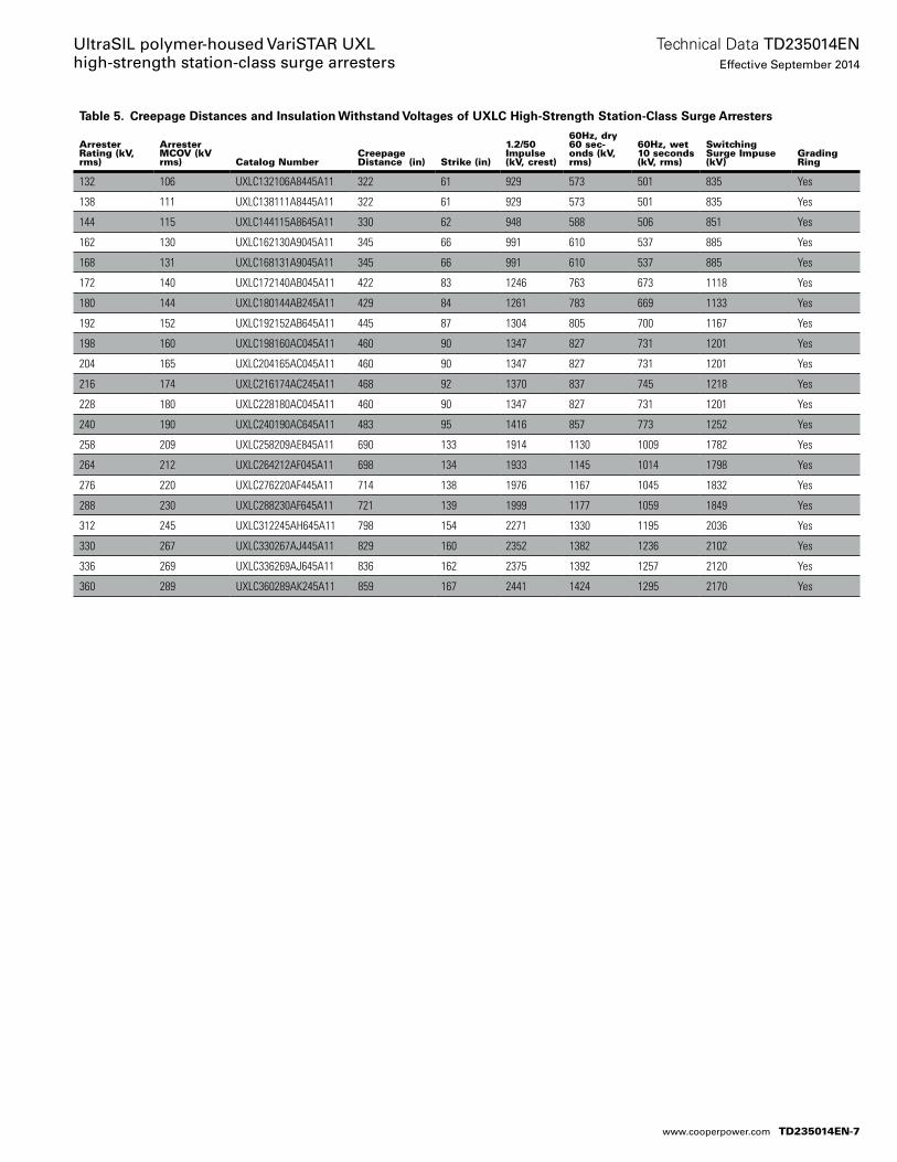
Table 5. Creepage Distances and Insulation Withstand Voltages of UXLC High-Strength Station-Class Surge Arresters
Arrester Rating (kV, rms)
Arrester MCOV (kV rms) Catalog Number
Creepage Distance (in) Strike (in)
1.2/50 Impulse (kV, crest)
60Hz, dry 60 sec-onds (kV, rms)
60Hz, wet 10 seconds (kV, rms)
Switching Surge Impuse (kV)
Grading Ring
132 106 UXLC132106A8445A11 322 61 929 573 501 835 Yes
138 111 UXLC138111A8445A11 322 61 929 573 501 835 Yes
144 115 UXLC144115A8645A11 330 62 948 588 506 851 Yes
162 130 UXLC162130A9045A11 345 66 991 610 537 885 Yes
168 131 UXLC168131A9045A11 345 66 991 610 537 885 Yes
172 140 UXLC172140AB045A11 422 83 1246 763 673 1118 Yes
180 144 UXLC180144AB245A11 429 84 1261 783 669 1133 Yes
192 152 UXLC192152AB645A11 445 87 1304 805 700 1167 Yes
198 160 UXLC198160AC045A11 460 90 1347 827 731 1201 Yes
204 165 UXLC204165AC045A11 460 90 1347 827 731 1201 Yes
216 174 UXLC216174AC245A11 468 92 1370 837 745 1218 Yes
228 180 UXLC228180AC045A11 460 90 1347 827 731 1201 Yes
240 190 UXLC240190AC645A11 483 95 1416 857 773 1252 Yes
258 209 UXLC258209AE845A11 690 133 1914 1130 1009 1782 Yes
264 212 UXLC264212AF045A11 698 134 1933 1145 1014 1798 Yes
276 220 UXLC276220AF445A11 714 138 1976 1167 1045 1832 Yes
288 230 UXLC288230AF645A11 721 139 1999 1177 1059 1849 Yes
312 245 UXLC312245AH645A11 798 154 2271 1330 1195 2036 Yes
330 267 UXLC330267AJ445A11 829 160 2352 1382 1236 2102 Yes
336 269 UXLC336269AJ645A11 836 162 2375 1392 1257 2120 Yes
360 289 UXLC360289AK245A11 859 167 2441 1424 1295 2170 Yes
TD235014EN-7
Technical Data TD235014ENEffective September 2014
UltraSIL polymer-housed VariSTAR UXL high-strength station-class surge arresters
www.cooperpower.com
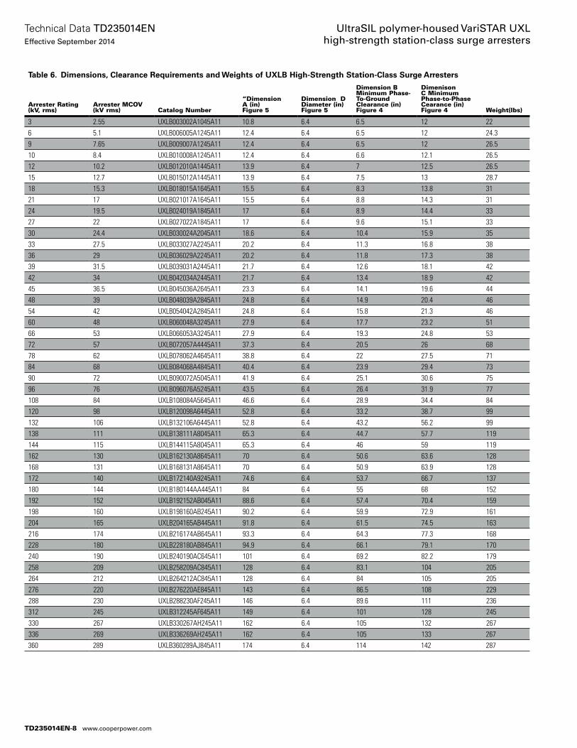
Table 6. Dimensions, Clearance Requirements and Weights of UXLB High-Strength Station-Class Surge Arresters
Arrester Rating (kV, rms)
Arrester MCOV (kV rms) Catalog Number
“Dimension A (in) Figure 5
Dimension D Diameter (in) Figure 5
Dimension B Minimum Phase-To-Ground Clearance (in) Figure 4
Dimenison C Minimum Phase-to-Phase Cearance (in) Figure 4 Weight(lbs)
3 2.55 UXLB003002A1045A11 10.8 6.4 6.5 12 226 5.1 UXLB006005A1245A11 12.4 6.4 6.5 12 24.39 7.65 UXLB009007A1245A11 12.4 6.4 6.5 12 26.510 8.4 UXLB010008A1245A11 12.4 6.4 6.6 12.1 26.512 10.2 UXLB012010A1445A11 13.9 6.4 7 12.5 26.515 12.7 UXLB015012A1445A11 13.9 6.4 7.5 13 28.718 15.3 UXLB018015A1645A11 15.5 6.4 8.3 13.8 3121 17 UXLB021017A1645A11 15.5 6.4 8.8 14.3 3124 19.5 UXLB024019A1845A11 17 6.4 8.9 14.4 3327 22 UXLB027022A1845A11 17 6.4 9.6 15.1 3330 24.4 UXLB030024A2045A11 18.6 6.4 10.4 15.9 3533 27.5 UXLB033027A2245A11 20.2 6.4 11.3 16.8 3836 29 UXLB036029A2245A11 20.2 6.4 11.8 17.3 3839 31.5 UXLB039031A2445A11 21.7 6.4 12.6 18.1 4242 34 UXLB042034A2445A11 21.7 6.4 13.4 18.9 4245 36.5 UXLB045036A2645A11 23.3 6.4 14.1 19.6 4448 39 UXLB048039A2845A11 24.8 6.4 14.9 20.4 4654 42 UXLB054042A2845A11 24.8 6.4 15.8 21.3 4660 48 UXLB060048A3245A11 27.9 6.4 17.7 23.2 5166 53 UXLB066053A3245A11 27.9 6.4 19.3 24.8 5372 57 UXLB072057A4445A11 37.3 6.4 20.5 26 6878 62 UXLB078062A4645A11 38.8 6.4 22 27.5 7184 68 UXLB084068A4845A11 40.4 6.4 23.9 29.4 7390 72 UXLB090072A5045A11 41.9 6.4 25.1 30.6 7596 76 UXLB096076A5245A11 43.5 6.4 26.4 31.9 77108 84 UXLB108084A5645A11 46.6 6.4 28.9 34.4 84120 98 UXLB120098A6445A11 52.8 6.4 33.2 38.7 99132 106 UXLB132106A6445A11 52.8 6.4 43.2 56.2 99138 111 UXLB138111A8045A11 65.3 6.4 44.7 57.7 119144 115 UXLB144115A8045A11 65.3 6.4 46 59 119162 130 UXLB162130A8645A11 70 6.4 50.6 63.6 128168 131 UXLB168131A8645A11 70 6.4 50.9 63.9 128172 140 UXLB172140A9245A11 74.6 6.4 53.7 66.7 137180 144 UXLB180144AA445A11 84 6.4 55 68 152192 152 UXLB192152AB045A11 88.6 6.4 57.4 70.4 159198 160 UXLB198160AB245A11 90.2 6.4 59.9 72.9 161204 165 UXLB204165AB445A11 91.8 6.4 61.5 74.5 163216 174 UXLB216174AB645A11 93.3 6.4 64.3 77.3 168228 180 UXLB228180AB845A11 94.9 6.4 66.1 79.1 170240 190 UXLB240190AC645A11 101 6.4 69.2 82.2 179258 209 UXLB258209AC845A11 128 6.4 83.1 104 205264 212 UXLB264212AC845A11 128 6.4 84 105 205276 220 UXLB276220AE845A11 143 6.4 86.5 108 229288 230 UXLB288230AF245A11 146 6.4 89.6 111 236312 245 UXLB312245AF645A11 149 6.4 101 128 245330 267 UXLB330267AH245A11 162 6.4 105 132 267336 269 UXLB336269AH245A11 162 6.4 105 133 267360 289 UXLB360289AJ845A11 174 6.4 114 142 287
TD235014EN-8
Technical Data TD235014ENEffective September 2014
UltraSIL polymer-housed VariSTAR UXL high-strength station-class surge arresters
www.cooperpower.com
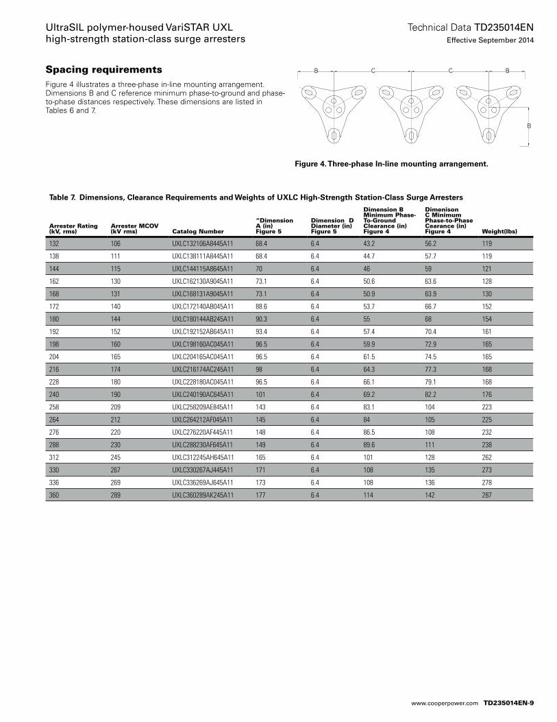
Table 7. Dimensions, Clearance Requirements and Weights of UXLC High-Strength Station-Class Surge Arresters
Arrester Rating (kV, rms)
Arrester MCOV (kV rms) Catalog Number
“Dimension A (in) Figure 5
Dimension D Diameter (in) Figure 5
Dimension B Minimum Phase-To-Ground Clearance (in) Figure 4
Dimenison C Minimum Phase-to-Phase Cearance (in) Figure 4 Weight(lbs)
132 106 UXLC132106A8445A11 68.4 6.4 43.2 56.2 119
138 111 UXLC138111A8445A11 68.4 6.4 44.7 57.7 119
144 115 UXLC144115A8645A11 70 6.4 46 59 121
162 130 UXLC162130A9045A11 73.1 6.4 50.6 63.6 128
168 131 UXLC168131A9045A11 73.1 6.4 50.9 63.9 130
172 140 UXLC172140AB045A11 88.6 6.4 53.7 66.7 152
180 144 UXLC180144AB245A11 90.3 6.4 55 68 154
192 152 UXLC192152AB645A11 93.4 6.4 57.4 70.4 161
198 160 UXLC198160AC045A11 96.5 6.4 59.9 72.9 165
204 165 UXLC204165AC045A11 96.5 6.4 61.5 74.5 165
216 174 UXLC216174AC245A11 98 6.4 64.3 77.3 168
228 180 UXLC228180AC045A11 96.5 6.4 66.1 79.1 168
240 190 UXLC240190AC645A11 101 6.4 69.2 82.2 176
258 209 UXLC258209AE845A11 143 6.4 83.1 104 223
264 212 UXLC264212AF045A11 145 6.4 84 105 225
276 220 UXLC276220AF445A11 148 6.4 86.5 108 232
288 230 UXLC288230AF645A11 149 6.4 89.6 111 238
312 245 UXLC312245AH645A11 165 6.4 101 128 262
330 267 UXLC330267AJ445A11 171 6.4 108 135 273
336 269 UXLC336269AJ645A11 173 6.4 108 136 278
360 289 UXLC360289AK245A11 177 6.4 114 142 287
Spacing requirementsFigure 4 illustrates a three-phase in-line mounting arrangement. Dimen sions B and C reference mini mum phase-to-ground and phase-to-phase distances respectively. These dimensions are listed in Tables 6 and 7.
CC BB
B
Figure 4. Three-phase In-line mounting arrangement.
TD235014EN-9
Technical Data TD235014ENEffective September 2014
UltraSIL polymer-housed VariSTAR UXL high-strength station-class surge arresters
www.cooperpower.com
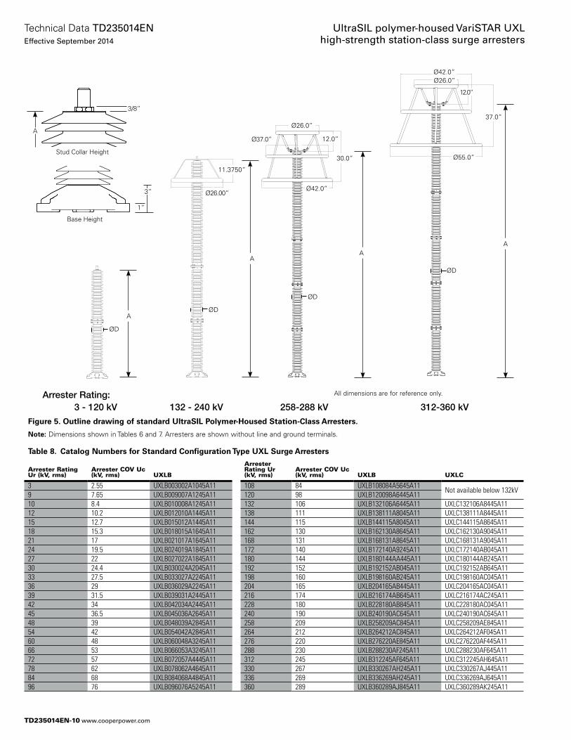
Figure 5. Outline drawing of standard UltraSIL Polymer-Housed Station-Class Arresters.
otee:N Dimensions shown in Tables 6 and 7. Arresters are shown without line and ground terminals.
Table 8. Catalog Numbers for Standard Configuration Type UXL Surge Arresters
Arrester Rating Ur (kV, rms)
Arrester COV Uc (kV, rms) UXLB
Arrester Rating Ur (kV, rms)
Arrester COV Uc (kV, rms) UXLB UXLC
3 2.55 UXLB003002A1045A11 108 84 UXLB108084A5645A11Not available below 132kV
9 7.65 UXLB009007A1245A11 120 98 UXLB120098A6445A1110 8.4 UXLB010008A1245A11 132 106 UXLB132106A6445A11 UXLC132106A8445A1112 10.2 UXLB012010A1445A11 138 111 UXLB138111A8045A11 UXLC138111A8445A1115 12.7 UXLB015012A1445A11 144 115 UXLB144115A8045A11 UXLC144115A8645A1118 15.3 UXLB018015A1645A11 162 130 UXLB162130A8645A11 UXLC162130A9045A1121 17 UXLB021017A1645A11 168 131 UXLB168131A8645A11 UXLC168131A9045A1124 19.5 UXLB024019A1845A11 172 140 UXLB172140A9245A11 UXLC172140AB045A1127 22 UXLB027022A1845A11 180 144 UXLB180144AA445A11 UXLC180144AB245A1130 24.4 UXLB030024A2045A11 192 152 UXLB192152AB045A11 UXLC192152AB645A1133 27.5 UXLB033027A2245A11 198 160 UXLB198160AB245A11 UXLC198160AC045A1136 29 UXLB036029A2245A11 204 165 UXLB204165AB445A11 UXLC204165AC045A1139 31.5 UXLB039031A2445A11 216 174 UXLB216174AB645A11 UXLC216174AC245A1142 34 UXLB042034A2445A11 228 180 UXLB228180AB845A11 UXLC228180AC045A1145 36.5 UXLB045036A2645A11 240 190 UXLB240190AC645A11 UXLC240190AC645A1148 39 UXLB048039A2845A11 258 209 UXLB258209AC845A11 UXLC258209AE845A1154 42 UXLB054042A2845A11 264 212 UXLB264212AC845A11 UXLC264212AF045A1160 48 UXLB060048A3245A11 276 220 UXLB276220AE845A11 UXLC276220AF445A1166 53 UXLB066053A3245A11 288 230 UXLB288230AF245A11 UXLC288230AF645A1172 57 UXLB072057A4445A11 312 245 UXLB312245AF645A11 UXLC312245AH645A1178 62 UXLB078062A4645A11 330 267 UXLB330267AH245A11 UXLC330267AJ445A1184 68 UXLB084068A4845A11 336 269 UXLB336269AH245A11 UXLC336269AJ645A1196 76 UXLB096076A5245A11 360 289 UXLB360289AJ845A11 UXLC360289AK245A11
3 - 120 kVArrester Rating:
3 - 120 kV
ØD
A
132 - 240 kV
Ø42.0”
Ø55.0”
37.0”
12.0”
Ø26.0”
11.3750
26.0000
132 - 240 kV
30.0
12.0
Ø26.0
Ø37.0
Ø42.0
258 - 288 kV
Ø26.0”
12.0”
Ø42.0”
30.0”
258-288 kV 312-360 kV
All dimensions are for reference only.
Ø26.00”
11.3750”
Ø37.0”
ØD
ØD
ØD
AA
A
3”
3/8”
1”
A
Stud Collar Height
Base Height
TD235014EN-10
Technical Data TD235014ENEffective September 2014
UltraSIL polymer-housed VariSTAR UXL high-strength station-class surge arresters
www.cooperpower.com
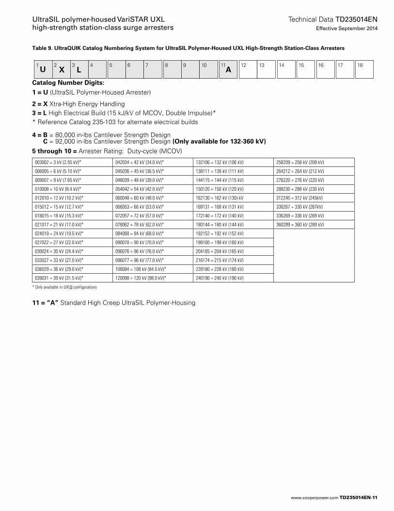
Table 9. UltraQUIK Catalog Numbering System for UltraSIL Polymer-Housed UXL High-Strength Station-Class Arresters
Catalog Number Digitse:
1 = U (UltraSIL Polymer-Housed Arrester)
2 = X Xtra-High Energy Handling3 = L High Electrical Build (15 kJ/kV of MCOV, Double Impulse)** Reference Catalog 235-103 for alternate electrical builds
4 = B = 80,000 in-lbs Cantilever Strength Design C = 92,000 in-lbs Cantilever Strength Design (Only available for 132-360 kV)
5 through 10 = Arrester Rating: Duty-cycle (MCOV)
11 = “A” Standard High Creep UltraSIL Polymer-Housing
1U
2 3 4 5 6 7 8 9 10 11 12 13 14 15 16 17 18X L
003002 = 3 kV (2.55 kV)* 042034 = 42 kV (34.0 kV)* 132106 = 132 kV (106 kV) 258209 = 258 kV (209 kV)
006005 = 6 kV (5.10 kV)* 045036 = 45 kV (36.5 kV)* 138111 = 138 kV (111 kV) 264212 = 264 kV (212 kV)
009007 = 9 kV (7.65 kV)* 048039 = 48 kV (39.0 kV)* 144115 = 144 kV (115 kV) 276220 = 276 kV (220 kV)
010008 = 10 kV (8.4 kV)* 054042 = 54 kV (42.0 kV)* 150120 = 150 kV (120 kV) 288230 = 288 kV (230 kV)
012010 = 12 kV (10.2 kV)* 060048 = 60 kV (48.0 kV)* 162130 = 162 kV (130) kV 312245 = 312 kV (245kV)
015012 = 15 kV (12.7 kV)* 066053 = 66 kV (53.0 kV)* 168131 = 168 kV (131 kV) 330267 = 330 kV (267kV)
018015 = 18 kV (15.3 kV)* 072057 = 72 kV (57.0 kV)* 172140 = 172 kV (140 kV) 336269 = 336 kV (269 kV)
021017 = 21 kV (17.0 kV)* 078062 = 78 kV (62.0 kV)* 180144 = 180 kV (144 kV) 360289 = 360 kV (289 kV)
024019 = 24 kV (19.5 kV)* 084068 = 84 kV (68.0 kV)* 192152 = 192 kV (152 kV)
027022 = 27 kV (22.0 kV)* 090070 = 90 kV (70.0 kV)* 198160 = 198 kV (160 kV)
030024 = 30 kV (24.4 kV)* 096076 = 96 kV (76.0 kV)* 204165 = 204 kV (165 kV)
033027 = 33 kV (27.0 kV)* 096077 = 96 kV (77.0 kV)* 216174 = 215 kV (174 kV)
036029 = 36 kV (29.0 kV)* 108084 = 108 kV (84.0 kV)* 228180 = 228 kV (180 kV)
039031 = 39 kV (31.5 kV)* 120098 = 120 kV (98.0 kV)* 240190 = 240 kV (190 kV)
A
* Only available in UXLB configurations
TD235014EN-11
Technical Data TD235014ENEffective September 2014
UltraSIL polymer-housed VariSTAR UXL high-strength station-class surge arresters
www.cooperpower.com
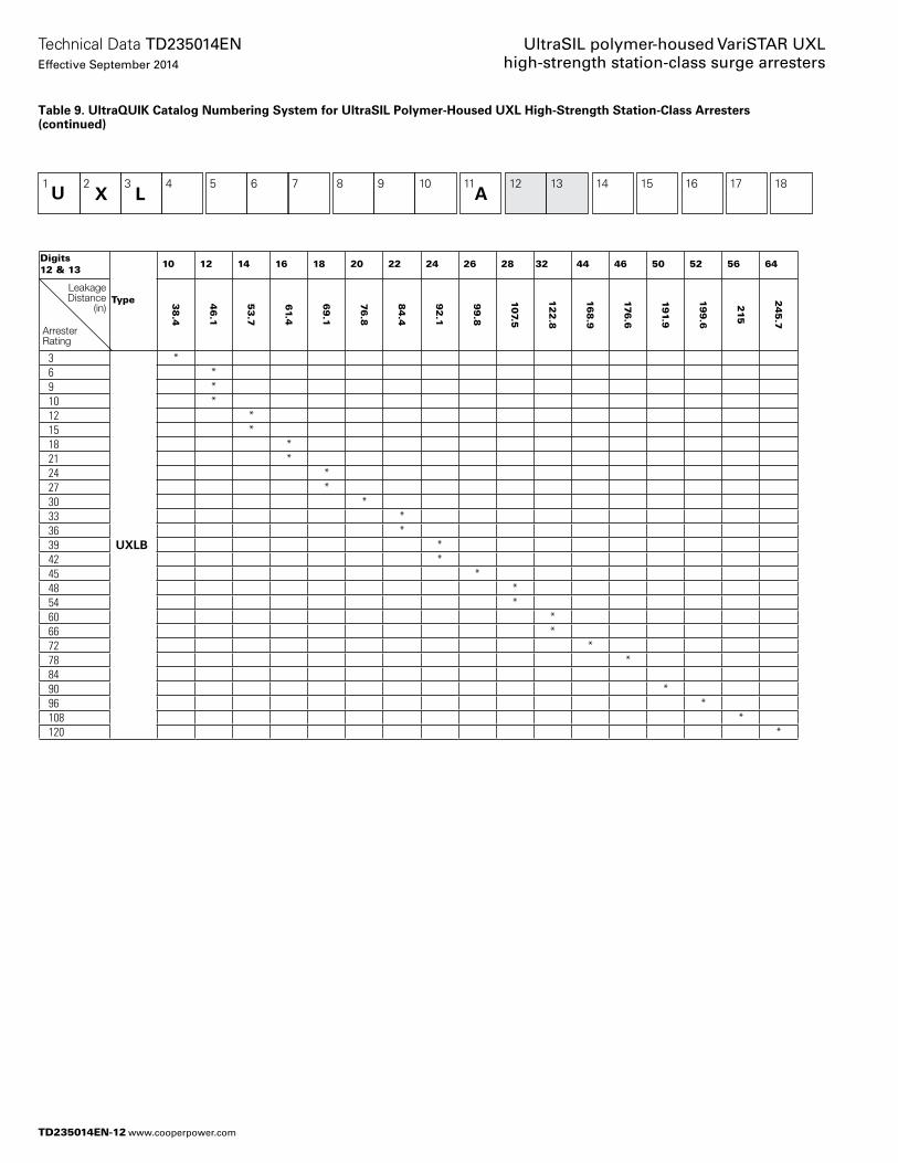
Digits 12 & 13
Type
10 12 14 16 18 20 22 24 26 28 32 44 46 50 52 56 64
38
.4
46
.1
53
.7
61.4
69
.1
76
.8
84
.4
92
.1
99
.8
107.5
12
2.8
16
8.9
176
.6
19
1.9
19
9.6
215
24
5.7
3
UXLB
* 6 * 9 * 10 * 12 * 15 * 18 * 21 * 24 * 27 * 30 * 33 * 36 * 39 * 42 * 45 * 48 * 54 * 60 * 66 * 72 * 78 * 84 90 * 96 * 108 * 120 *
1U
2 3 4 5 6 7 8 9 10 11 12 13 14 15 16 17 18X L A
Table 9. UltraQUIK Catalog Numbering System for UltraSIL Polymer-Housed UXL High-Strength Station-Class Arresters (continued)
LeakageDistance
(in)
Arrester Rating
TD235014EN-12
Technical Data TD235014ENEffective September 2014
UltraSIL polymer-housed VariSTAR UXL high-strength station-class surge arresters
www.cooperpower.com
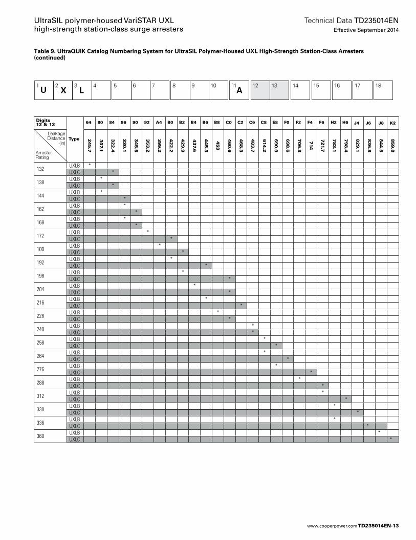
Table 9. UltraQUIK Catalog Numbering System for UltraSIL Polymer-Housed UXL High-Strength Station-Class Arresters (continued)
1U
2 3 4 5 6 7 8 9 10 11 12 13 14 15 16 17 18X L A
Digits 12 & 13
Type
64 80 84 86 90 92 A4 B0 B2 B4 B6 B8 C0 C2 C6 C8 E8 F0 F2 F4 F6 H2 H6 J4 J6 J8 K2
24
5.7
30
7.1
32
2.4
33
0.1
34
5.5
35
3.2
39
9.2
42
2.2
42
9.9
43
7.6
44
5.3
45
3
46
0.6
46
8.3
48
3.7
614
.2
69
0.9
69
8.6
70
6.3
714
72
1.7
78
3.1
79
8.4
82
9.1
83
6.8
84
4.5
85
9.8
132UXLB *UXLC *
138UXLB *UXLC *
144UXLB *UXLC *
162UXLB *UXLC *
168UXLB *UXLC *
172UXLB *UXLC *
180UXLB *UXLC *
192UXLB *UXLC *
198UXLB *UXLC *
204UXLB *UXLC *
216UXLB *UXLC *
228UXLB *UXLC *
240UXLB *UXLC *
258UXLB *UXLC *
264UXLB *UXLC *
276UXLB *UXLC *
288UXLB *UXLC *
312UXLB *UXLC *
330UXLB *UXLC *
336UXLB *UXLC *
360UXLB *UXLC *
LeakageDistance
(in)
Arrester Rating
TD235014EN-13
Technical Data TD235014ENEffective September 2014
UltraSIL polymer-housed VariSTAR UXL high-strength station-class surge arresters
www.cooperpower.com
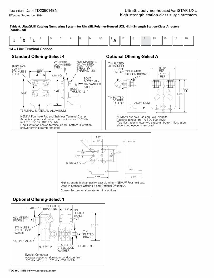
1U
2 3 4 5 6 7 8 9 10 11 12 13 14 15 16 17 18LX A
TIN PLATED SILICON BRONZE
ALUMINUM
TIN PLATED COPPER
ALLOY
TIN PLATED ALUMINUM
BRONZE ALLOY
3.50”REF1.75”REF
4.72”REF
4.25”
NEMA® Four-hole Pad and Two EyeboltsAccepts conductors 1/0 SOL-500 MCM(Top illustration shows two eyebolts, bottom illustration shows two eyebolts removed)
1.75” SQ
4.72”4.25”
3.50”REF
BOLT THREAD–.51”
NUT MATERIAL–GALVANIZED STEEL NUT THREAD–.51”
WASHERS–GALVANIZED STEEL
BOLT MATERIAL–GALVANIZED STEEL
Eyebolt Connector Accepts copper or aluminum conductors from .16” dia. (#6) up to .57” dia. (250 MCM)
THREAD–.51”TIN PLATED BRASS NUT TIN
PLATED BRASS NUT
THREAD–.63”
TIN PLATED BRASS
STAINLESS STEEL LOCK WASHER
1.65”
1.65”
3.19”
Optional Offering-Select A
1.97”
1.57”1.97”
4.25” 1.97”
1.57”
.69”
1.38”
3.50”
10 Hole Typ 4 PL
.51”
2.75”
High strength, high ampacity, cast aluminum NEMA® Four-hold pad.Used in Standard Offering 4 and Optional Offering A.
Consult factory for alternate terminal options.
ALUMINUM BRONZE
STAINLESS STEEL LOCK WASHER
COPPER ALLOY
Optional Offering-Select 1
TERMINAL MATERIAL–ALUMINUM
NEMA® Four-hole Pad and Stainless Terminal ClampAccepts copper or aluminum conductors from .16” dia. (#6) to 1.15” dia. (1000 MCM).(Top illustration shows terminal clamp, bottom illustration shows terminal clamp removed)
TERMINAL CLAMP–STAINLESS STEEL
Standard Offering-Select 4
14 = Line Terminal Options
Table 9. UltraQUIK Catalog Numbering System for UltraSIL Polymer-Housed UXL High-Strength Station-Class Arresters (continued)
TD235014EN-14
Technical Data TD235014ENEffective September 2014
UltraSIL polymer-housed VariSTAR UXL high-strength station-class surge arresters
www.cooperpower.com
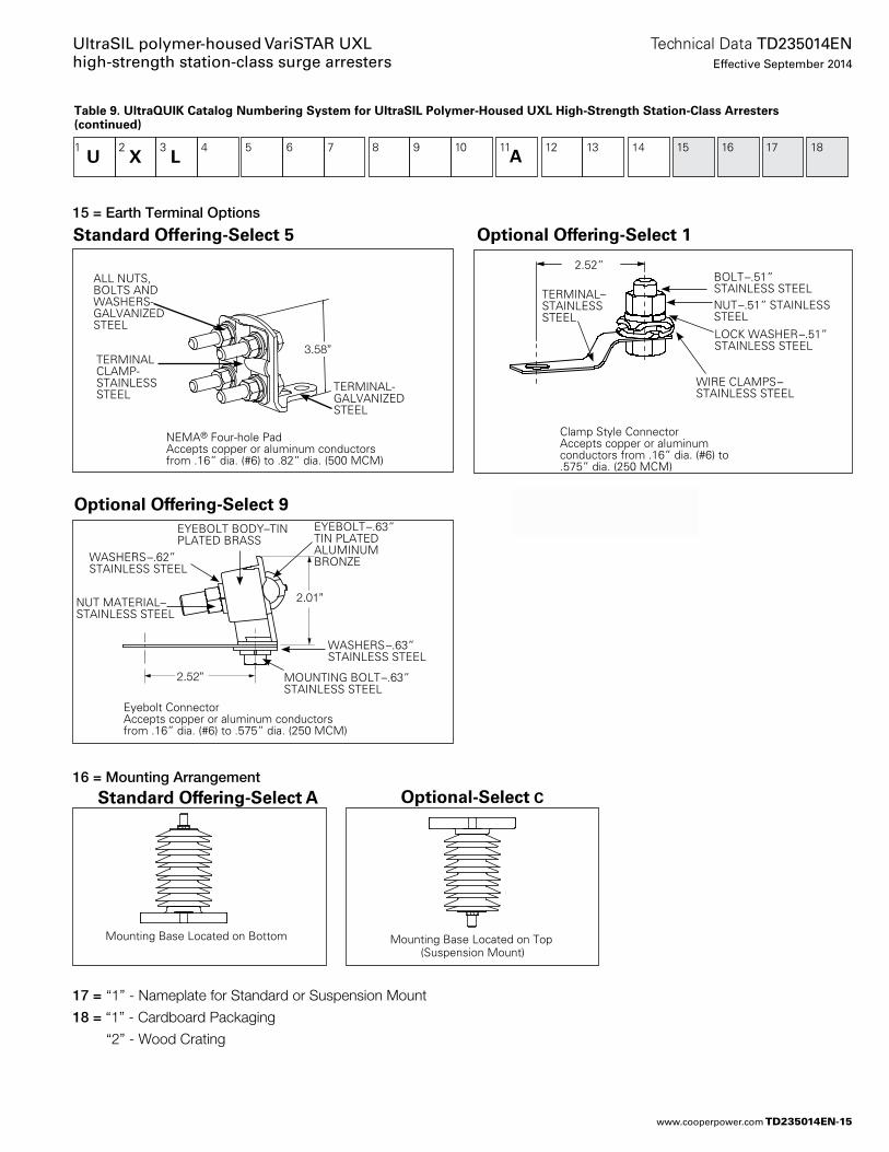
Table 9. UltraQUIK Catalog Numbering System for UltraSIL Polymer-Housed UXL High-Strength Station-Class Arresters (continued) 1
U 2 3 4 5 6 7 8 9 10 11 12 13 14 15 16 17 18
X L
Mounting Base Located on Bottom Mounting Base Located on Top (Suspension Mount)
15 = Earth Terminal Options
16 = Mounting Arrangement
17 = “1” - Nameplate for Standard or Suspension Mount
18 = “1” - Cardboard Packaging
“2” - Wood Crating
2.52”
2.01”
Eyebolt Connector Accepts copper or aluminum conductors from .16” dia. (#6) to .575” dia. (250 MCM)
EYEBOLT BODY–TIN PLATED BRASS
EYEBOLT–.63” TIN PLATED ALUMINUM BRONZE
MOUNTING BOLT–.63” STAINLESS STEEL
WASHERS–.62” STAINLESS STEEL
NUT MATERIAL–STAINLESS STEEL
WASHERS–.63” STAINLESS STEEL
120 mm
91 mm
NEMA® Four-hole Pad Accepts copper or aluminum conductors from .16” dia. (#6) to .82” dia. (500 MCM)
3.58”
TERMINAL-GALVANIZED STEEL
ALL NUTS, BOLTS AND WASHERS-GALVANIZED STEEL
TERMINAL CLAMP-STAINLESS STEEL
Standard Offering-Select 5
2.52”
Clamp Style ConnectorAccepts copper or aluminum conductors from .16” dia. (#6) to .575” dia. (250 MCM)
TERMINAL–STAINLESS STEEL
WIRE CLAMPS–STAINLESS STEEL
BOLT–.51” STAINLESS STEELNUT–.51” STAINLESS STEELLOCK WASHER–.51” STAINLESS STEEL
Optional Offering-Select 1
Optional Offering-Select 9
Standard Offering-Select A Optional-Select C
A
TD235014EN-15
Technical Data TD235014ENEffective September 2014
UltraSIL polymer-housed VariSTAR UXL high-strength station-class surge arresters
www.cooperpower.com
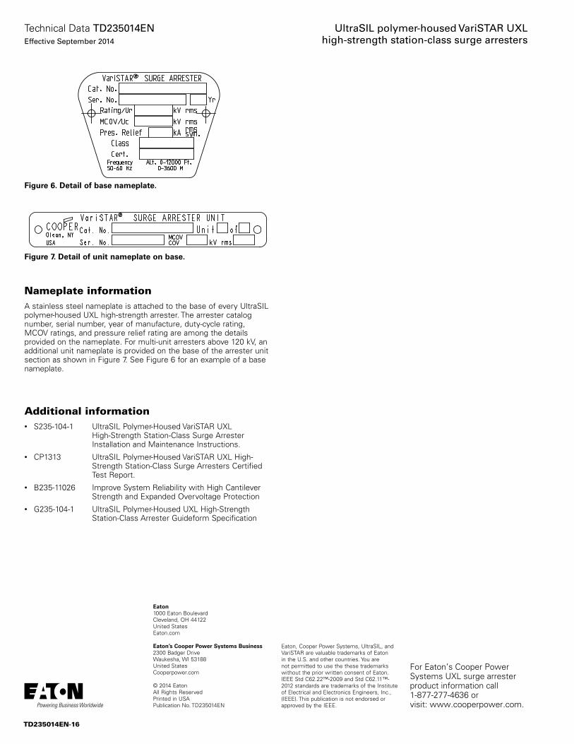
Additional information• S235-104-1 UltraSIL Polymer-Housed VariSTAR UXL
High-Strength Station-Class Surge Arrester Installation and Maintenance Instructions.
• CP1313 UltraSIL Polymer-Housed VariSTAR UXL High- Strength Station-Class Surge Arresters Certified Test Report.
• B235-11026 Improve System Reliability with High Cantilever Strength and Expanded Overvoltage Protection
• G235-104-1 UltraSIL Polymer-Housed UXL High-Strength Station-Class Arrester Guideform Specification
Nameplate informationA stainless steel nameplate is at tached to the base of every UltraSIL polymer-housed UXL high-strength arrester. The arrester catalog number, serial number, year of manufacture, duty-cycle rating, MCOV ratings, and pressure relief rating are among the details provided on the nameplate. For multi-unit arresters above 120 kV, an additional unit nameplate is provided on the base of the arrester unit section as shown in Figure 7. See Figure 6 for an example of a base nameplate.
Figure 6. Detail of base nameplate.
Figure 7. Detail of unit nameplate on base.
Eaton, Cooper Power Systems, UltraSIL, and VariSTAR are valuable trademarks of Eaton in the U.S. and other countries. You are not permitted to use the these trademarks without the prior written consent of Eaton.IEEE Std C62.22™-2009 and Std C62.11™-2012 standards are trademarks of the Institute of Electrical and Electronics Engineers, Inc., (IEEE). This publication is not endorsed or approved by the IEEE.
UltraSIL polymer-housed VariSTAR UXL high-strength station-class surge arresters
Eaton1000 Eaton BoulevardCleveland, OH 44122United StatesEaton.com
Eaton’s Cooper Power Systems Business2300 Badger DriveWaukesha, WI 53188United StatesCooperpower.com
© 2014 EatonAll Rights ReservedPrinted in USAPublication No. TD235014EN
Technical Data TD235014ENEffective September 2014
For Eaton’s Cooper Power Systems UXL surge arrester product information call 1-877-277-4636 or visit: www.cooperpower.com.
TD235014EN-16

Eaton and Cooper Power Systems are valuable trademarks of Eaton in the U .S . and other countries . You are not permitted to use these trademarks without the prior written consent of Eaton .
All other trademarks are property of their respective owners .
Eaton1000 Eaton BoulevardCleveland, OH 44122United StatesEaton .com
Eaton’s Cooper Power Systems Business2300 Badger DriveWaukesha, WI 53186United States CooperPower .com
© 2014 EatonAll Rights ReservedPrinted in USA