Embed Size (px)
Citation preview
Eaton’s Weatherhead®
Hose Assembly Master Catalog

A
B
C
D
E
F
G
H
I
J
K
L
M
N
O
Application Data Section ASafety Information A-2 thru A-4Warranty A-3Hose Selection Chart A-4 thru A-9 Chemical Compatibility Chart A-10 thru A-14Hose Fittings Pressure Chart A-15 thru A-16Fitting Identification A-17 thru A-20Numbering Systems Hose A-21 Hose Fittings A-22 Hose Fittings Identification A-23 thru A-28 Conversion Chart A-29Skiving Procedures A-30Hose Installation and Failure Analysis A-31 thru A-32Qualified Hoses for Marine Applications A-33Qualified Hoses for American Bureau of Shipping (ABS) A-34Torque Specifications A-35Tubing Selection A-36 thru A-37 Flow/Velocity Chart A-38 RecommendedWall Thickness Tables A-39 thru A-42 Hose Hydraulic Section B General Purpose Section C Industrial Section D Fuel Section E Silicone Section F Air Conditioning Section G Truck Section H Teflon® Section I Hose FittingsCrimp Section J Coll-O-Crimp® ‘E’ Series Hose Fittings J-2 thru J-8 Coll-O-Crimp 069 ‘E’ Series Hose Fittings J-9 thru J-12 Coll-O-Crimp 327 ‘E’ Series Hose Fittings J-13 thru J-14 Coll-O-Crimp 336 ‘E’ Series Hose Fittings J-13 thru J-18 Coll-O-Crimp 470 ‘E’ Series Hose Fittings J-19 thru J-23 Coll-O-Crimp 757 ‘E’ Series Hose Fittings J-24 thru J-31 Coll-O-Crimp 057 ‘P’ Series Hose Fittings J-32 Coll-O-Crimp 229 ‘P’ Series Hose Fittings J-33 Coll-O-Crimp 265 ‘P’ Series Hose Fittings J-34 Coll-O-Crimp 338 ‘P’ Series Hose Fittings J-35 thru J-37 Coll-O-Crimp ‘S’ Series Hose Fittings J-38 Coll-O-Crimp ‘U’ Series Hose Fittings J-39 thru J-57 Coll-O-Crimp 430 ‘U’ Series No Skive Hose Fittings J-58 thru J-68 WeatherGRIP™ ‘Z’ Series Hose Fittings J-69 thru J-94 WeatherTIGHT™ 4SP/6SP Series Hose Fittings J-95 thru J-105 Field Attachable Section K Field Attachable 009 ‘B’ Series Hose Fittings K-2 Field Attachable 057 ‘B’ Series Hose Fittings K-3 thru K-4 Field Attachable 100 ‘B’ Series Hose Fittings K-5 thru K-7 Field Attachable 105 ‘B’ Series Hose Fittings K-8 Field Attachable 338 ‘B’ Series Hose Fittings K-9 thru K-11 Field Attachable 069 ‘D’ Series Hose Fittings K-12 thru K-13 Field Attachable ‘K’ Series Hose Fittings K-14 Field Attachable 039 ‘K’ Series Hose Fittings K-15 Field Attachable 104 ‘N’ Series Hose Fittings K-16 thru K-18 Field Attachable 213 ‘N’ Series Hose Fittings K-19 thru K-21 Field Attachable 247 ‘N’ Series Hose Fittings K-22 thru K-26 Field Attachable 425 ‘N’ Series Hose Fittings K-27 thru K-29 Field Attachable 436 ‘N’ Series Hose Fittings K-30 thru K-31
Table of ContentsApplication Data
Hydraulic Hose
General Purpose Hose
Industrial Hose
Fuel Hose
Silicone Hose
Air Conditioning Hose
Truck Hose
Teflon® Hose
Crimp Fittings
Field Attachable Fittings
Adapters, Tube Fittings & Connectors
Accessories
Assembly Equipment
Glossary & Index
Ho
se Fitting
sH
ose P
rod
ucts
Teflon® is a registered trademark of DuPont used under license by Eaton.

EATON Weatherhead Hose Assembly Master Catalog W-HYOV-MC002-E3 February 2011 3
A
B
C
D
E
F
G
H
I
J
K
L
M
N
O
www.eaton.com/hydraulics
E-Z Clip® System Section K End Connections and O-Rings K-32 thru K-33 Hose Fittings K-34 thru K-58 Cages, Clips and Lifesavers K-59 Aluminum Lifesaver K-60 Assembly Tools K-61 Components Ordering and Identifying K-62 Assembly Instructions K-63 thru K-64 Adapters, Tube Fittings and Connectors Section LHose to Order & Size Designation L-2Steel Adapters L-3 thru L-16Swivel Adapters L-17 thru L-23For-Seal® Adapters L-24 thru L-34JIC 37° Flare-Twin® Fittings L-35 thru L-64Steel Din Fittings L-65 thru L-67Straight Thread O-Rings L-68 thru L-70Din Connectors L-71Metric Connectors L-72 thru L-73BSP Connectors L-74 thru L-76Special Adapters L-77Steel Flareless Ermeto® Connectors L-78 thru L-88Split Flange Adapters and Kits L-89 thru L-92STC Connectors How To Order, STC Overview L-93 thru L-95 Assembly Method and Verification L-96 Female STC Cap and Male STC Plug L-97 STC Adapters L-98 thru L-106 STC Repair Adapters L-107 Accessories and Sales Tools L-108 Accessories Section MHose Abrasion Sleeves, Guards, Firesleeve M-2 thru M-11Ready-Made Hose Assemblies M-12 thru M-18 JetCleaner, Insertion Gauge, Pressure Gauge Kit M-19Hose Spacers, Protectors M-20Flaretite Seals M-21Guardian Sleeves M-22Bundling Sleeves M-23Bundling Straps M-24 thru M-25Hose and Gear Clamps M-26 thru M-28 Assembly Equipment Section NIndex to Crimp Packages N-2 thru N-3Crimping Machines - Portable Coll-O-Crimp Portable T-464 & T-466 N-4 Coll-O-Crimp Portable T-465 N-5 thru N-6 Coll-O-Crimp T-465 Crimping Procedures N-7 Air Conditioning Portable Crimper, T-477 N-8 T-477 Crimping Procedures N-9 thru N-12 Coll-O-Crimp Portable T-480 N-13 thru N-15 ET1000 Portable Crimp Machine N-16 ET1000 Crimp Procedures N-17Crimping Machines - Stationary Coll-O-Crimp Shop Press Tooling, T-400-17 N-18 Coll-O-Crimp I, T-400, T-407 N-19 thru N-20 Coll-O-Crimp SUPER I, T-420 N-21 Coll-O-Crimp ET4001 N-22 T-440, ET4000 & ET4001 Repair Items N-23Crimping Machines - Variable Coll-O-Crimp ET4020 N-24 Coll-O-Crimp ET4040 N-25
Tooling and Accessories Coll-O-Crimp Collet Kits N-26 thru N-29 WeatherGRIP Tooling N-30 thru N-31 Coll-O-Crimp Spacer Rings N-32 Coll-O-Crimp Air & Hydraulic Pumps N-33 thru 35 Competitor Conversion Kits N-36 Tube Flaring Tools N-37 Hose Cutting Equipment N-38 thru N-40 Presetting Tools N-41 Hose Bore Cleaning Brushes N-42 Skiving Tools & Wrenches N-43 Power Steering Assembly N-44 thru N-46 Cable Controls N-47 thru N-48 Assortments N-49 thru N-67Equipment Cabinets, Tool Boxes, and Plastic Bags N-68 thru N-70 Label Sets & Mylar Hose Labels N-71 Field Attachable Assembly N-72 thru N-73 Glossary and Index Section OGlossary O-2 thru O-6Index O-7 thru O-16
Table of Contents (continued)
Additional Eaton Fluid Conveyance Products can be found in these catalogs:
Product Line Catalog Number
Synflex™ Hose and Fittings E-HOOV-MC001-E1Eaton Quick Disconnect Couplings E-MEQD-MC001-E1Walterscheid™ Tube Fittings E-MEFI-MC002-E1Eaton Swivel Joints E-MESW-MC001-EEaton Brass Products E-BRFI-MC001-E3Weatherhead™ Crimp Specifications Manual W-HOOV-TM001-E2Eaton Industrial Hose E-HOOV-MC003-E1

EATON Weatherhead Hose Assembly Master Catalog W-HYOV-MC002-E3 May 20104
Introduction to Weatherhead
Weatherhead® products, which became part of Eaton Hydraulics in 2002, have one of the industry’s broadest offerings of hydraulic hose, hose fittings, assembly equipment, tube fittings, couplings and support accessories. Weatherhead products are widely used in industrial and mobile fluid power and fluid conveyance applications. Eaton also supplies Weatherhead thermoplastic tubing in sizes from 1/8th through 1 inch for use in robotics, air tools, air and water supply, and beverage dispensing.
Eaton’s Hydraulics Group is a worldwide leader in the design, manufacture and marketing of a comprehensive line of reliable, high-efficiency hydraulic systems and components for use in mobile and industrial applications. Mobile and industrial markets include agriculture, construction, mining, forestry, utility, material handling, earthmoving, truck and bus, machine tools, molding, primary metals, automotive, power generation, port machinery and entertainment.
Weatherhead has one of the industry’s broadest offerings of hose and fittings that are widely used throughout multiple market applications.

EATON Weatherhead Hose Assembly Master Catalog W-HYOV-MC002-E3 February 2011 A-1
Safety Information A-2 thru A-3Hose Selection Chart A-3 thru A-9 Chemical Compatibility Chart A-10 thru A-14 Pressure Charts A-15 thru A-16Fitting Identification A-17 thru A-20Numbering Systems A-21 thru A-28Conversion Chart A-29Skiving Procedures A-30
Hose Installation and Failure Analysis A-31 thru A-32Qualified Hoses for Marine Applications A-33Qualified Hoses for American Bureau of Shipping (ABS) A-34Torque Specifications A-35Tubing Selection A-36 thru A-37Flow/Velocity Chart A-38Recommended Wall Thickness Tables A-39 thru A-42
Application Data
Table of Contents

EATON Weatherhead Hose Assembly Master Catalog W-HYOV-MC002-E3 February 2011A-2
A
B
C
D
E
F
G
H
I
J
K
L
M
N
O
Ap
plicatio
n D
ata
WARNINGFlexible hose lines offer many advantages over rigid tubing including routing ease, vibration absorption, sound deafening and the ability to accommodate movement of connected components. However, hose lines require caution in use not only to provide long service, but also to guard against potentially dangerous failure.
ImportantThe user should carefully observe the precautions listed in this catalog or brochure, including the recommendations on the selection of hose and fittings on the relevant pages on fluid compatibility. In addition, care should be taken not to exceed the minimum bend radius listed for each hose size and type in the hose section. Maximum operating pressure should not exceed pressures listed in the hose data. Instructions for assembling fittings to different hose should be followed carefully to ensure the performance of the completed assembly.
WARNINGEaton’s Weatherhead fitting tolerances are engineered to match Eaton’s Weatherhead hose tolerances. The use of Weatherhead fittings on hose supplied by other manufacturers and/or the use of Weatherhead hoses with fittings supplied by other manufactures may result in the production of unreliable and unsafe hose assemblies and is neither recommended nor authorized by Eaton Corporation or any of its affiliates or subsidiaries.
WARNINGApplication considerations must be observed in selecting appropriate components for the application of these products contained herein. The failure to follow the recommendations set forth in this catalog may result in an unstable application which may result in serious personal injury or property damage. Eaton corporation or any of its affiliatEs or subsidiariEs shall not bE subjEct to and disclaims any obligations or liabilitiEs (including but not limitEd to all consEquEntial, incidEntal and contingEnt damagEs) arising from tort claims (including without limitation nEgligEncE and strict liability) or othEr thEoriEs of law with rEspEct to any hosE assEmbliEs not producEd from gEnuinE wEathErhEad hosE fittings, hosE and wEathErhEad approvEd EquipmEnt, and in conformancE with Eaton’s wEathErhEad procEss and product instructions for Each spEcific hosE assEmbly. Failure to follow these processes and product instructions and limitations could lead to premature hose assembly failures resulting in property damage, serious injury or death.
Important Safety Information

EATON Weatherhead Hose Assembly Master Catalog W-HYOV-MC002-E3 February 2011 A-3
A
B
C
D
E
F
G
H
I
J
K
L
M
N
O
Ap
plica
tio
n D
ata
RoutingIf the user follows the recommendations on hose line routing and installation as provided for herein, improved safety and longer service life of any hose installation will result.
Hose InstallationProper installation of the hose is essential to the proper operation and safe use of the hose and related equipment. Improper installation of the hose can result in serious injury or property damage caused by spraying fluids or flying projectiles. In order to avoid serious bodily injury or property damage resulting from improper installation of the hose, you should carefully review the information in this catalog regarding hose installation.
Some of the factors you must consider in installing the hose properly are:
• Changes in length• Proper bend radius• Protection from high
temperature sources• Elbows and adapters to
relieve strain • Rubbing or abrasion• Twisting• Improper hose movement
These factors and the other information in this catalog regarding hose installation should be considered by you before installing the hose. If you have any questions regarding proper hose installation, please contact Eaton Technical Support at 1-888-258-0222.
Hose Maintenance
Proper maintenance of the hose is essential to the safe use of the hose and related equipment. Hose should be stored in a dry place. Hose should also be visually inspected. Any hose that has a cut or gouge in the cover that exposes the reinforcement should be retired from service. Hoses should also be inspected for kinking or broken reinforcement. If the outside diameter of the hose is reduced by 20% at the spot where it is bent then the hose should be retired from service. Inadequate attention to maintenance of the hose can result in hose leakage, bursting, or other failure which can cause serious bodily injury or property damage from spraying fluids, flying projectiles, or other substances.
Hose and Field Attachable Hose Fittings
Weatherhead Hose and Field Attachable Hose Fittings have been engineered and designed as a complete hose assembly system. Component compatibility along with the use of quality components insures the production of reliable hose assemblies when assembled properly. The use or intermixing of fittings and hose not specifically engineered and designed for use with each other may result in the production of unsafe or unreliable hose assemblies.
This can result in hose assembly leakage, hose separation or other failures which can cause serious bodily injury or property damage from spraying fluids, flying projectiles, or other substances. The Eaton warranty is limited to apply only when Weatherhead Field Attachable Hose Fittings are used on compatible Weatherhead hose. See www.eaton.com/hydraulics/warranty for warranty information.
Weatherhead Hose, Hose Fittings and Assembly Equipment Compatibility
Weatherhead Equipment, Weatherhead Hose Fittings and Weatherhead Hose have been engineered and designed as a complete hose assembly system. Each component of the Weatherhead hose assembly system is compatible with other Weatherhead components to which it relates. Component compatibility, along with the use of quality components, insures the production of reliable hose assemblies when assembled properly. The use or intermixing of fittings and hose not specifically engineered and designed for use with each other and Weatherhead equipment is not recommended and may result in the production of unsafe or unreliable hose assemblies. This can result in hose assembly leakage, hose separation or other failures which can cause serious bodily injury or property damage from spraying fluids, flying projectiles, or other substances. The Eaton warranty is limited to apply only when Weatherhead Hose Fittings and compatible Weatherhead Hose are used with Weatherhead assembly equipment.
Important Safety Information
Warranty
Current warranty information can be found at:
www.eaton.com/hydraulics/warranty

EATON Weatherhead Hose Assembly Master Catalog W-HYOV-MC002-E3 February 2011A-4
A
B
C
D
E
F
G
H
I
J
K
L
M
N
O
Ap
plicatio
n D
ata
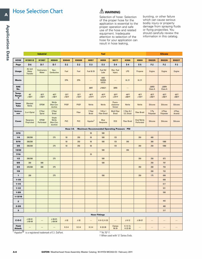
Hose Selection Chart WARNINGSelection of hose: Selection of the proper hose for the application is essential to the proper operation and safe use of the hose and related equipment. Inadequate attention to selection of the hose for your application can result in hose leaking,
bursting, or other failure which can cause serious bodily injury or property damage from spraying fluids or flying projectiles. You should carefully review the information in this catalog.
How to use chart: Locate the hose I.D. required and move to the right to the correct pressure. Then move up or down in this column for data on material, temperature, etc. to quickly determine whether the hose meets your requirements. For complete information on any hose refer to hose catalog page number at bottom of column.
HOSE H017 H039 H104 H114 H145 H145R H146 H190 H190H H245 H245L H280
Page B-3 B-2 B-3 B-6 B-6 B-7 B-7 B-4 B-5 B-9 B-10 B-11
UsageGeneral Purpose
HydraulicSuction Hydraulic
Ag. Hyd. & Hyd.
SyntheticHydraulic Construction
Ag. Hyd. & Hyd.
Synthetic
Diamond Advantage
High Temp. Hydraulics Hydraulic Low Temp
FlexingDiamond
Advantage
Meets USCG MSHA
USCG ABS MSHA
USCG MSHA ABS
MSHAABS
USCG MSHA
— —
MSHA, USCG, ISO 1436a, EN 853 Type
1SN
MSHA, ISO1436a
USCG MSHA ABS
USCG2 MSHA
ABS, USCG, MSHA,
ISO 1436, EN 857,
Type 2SC
SAE No.
J1942/1, 100R3
100R4 J1942/1
J1942 /1/1 100R1AT — J1942/1,
100R17 100R17 —J1942/1,
100R1 AT, Type S
100R1 AT, 1SN, EN853
J1942 100R16 100R16
J1942, Code H, 100R16,
Type S
Temp. Range
˚F
-40°F+212°F
-40°F+275°F
-40°F+212°F
-40°F+250°F
See Page 55
-40°F+212°F
-65°F+250°F
-40°F+260°F -40 - +302˚F -40°F
+212°F -70 - +212˚F -40°F+260°F
Inner Tube Nitrile CPE Nitrile Hytrel1 Nitrile Nitrile Hytrel1 Nitrile CPE Nitrile Low Temp.
Nitrile Nitrile
Reinforce- ment
2 Fiber Braids
2 Fiber Ply & Helical
Wire
1 Steel Braid
1 Steel Braid
1 Steel Braid†
1-2 Steel Braids
1 Steel Braid
1 Steel Braid
1 Steel Braid
2 Steel Braids
2 Wire Braids
2 Steel Braids
Cover Neoprene Neoprene Neoprene Neoprene Neoprene UHMWPE Polyester Braid
Weather- SHIELD™ CPE Neoprene Weather-
SHIELD™Weather- SHIELD™
Hose I.D. - Maximum Recommended Operating Pressure - PSI
3/16
1/4 1250 2750 3000 3045 3000 3000 3700 3265 5000 6000 6500
5/16
3/8 1125 2250 3000 3045 3000 3000 3400 2610 4000 5000 5300
13/32
7/16
1/2 1000 2000 3000 3045 3000 3000 2900 2320 3500 4500 4500
5/8 1500 3045 3000 1885 1885 2750 4000 4000
3/4 750 300† 1250 3045 3000 2000 1525 2250 3500 3500
7/8
1 565 250† 1000 3045 3000 1500 1275 2000 2800 3000
1-1/8
1-1/4 375 200† 625 1000 900 1625 2300 2500
1-1/2 150 750 2000 2000
1-3/8
1-13/16
2 100 600 1500 1600
2-3/8
3
Hose Fittings
C-O-C J-39-57J-38, J-39-57, J-58-68,
J-69-94
J-38, J-39-57, J-69-94
J-38, J-39-57
J-69-94, J-38, J-39-57, J-58-68
J-69-94 J-39-57 J-69-94 J-69-94J-69-94,
J-38, J-39-57, J-58-68
J-69-94 J-69-94
Field Attach. — K-14, K-15 K-16-18 — — — — — — — — —
Hydraulic
1 hypalon® is a registered trademark of E.i. dupont.
2 firesleeve required for fuel applications.
**at 70° f. † when used with 'u' series Ends.

EATON Weatherhead Hose Assembly Master Catalog W-HYOV-MC002-E3 February 2011 A-5
A
B
C
D
E
F
G
H
I
J
K
L
M
N
O
Ap
plica
tio
n D
ata
Hose Selection Chart WARNINGSelection of hose: Selection of the proper hose for the application is essential to the proper operation and safe use of the hose and related equipment. Inadequate attention to selection of the hose for your application can result in hose leaking,
bursting, or other failure which can cause serious bodily injury or property damage from spraying fluids or flying projectiles. You should carefully review the information in this catalog.
HOSE H290 H290H H324 H325 H335 H336 H345 H350 H400 H421 H425 H430 H430R
Page B-13 B-13 B-2 B-10 B-19 B-19 B-5 B-8 B-9 B-18 B-12 B-14 B-15
Usage Diamond Advantage
High Temp. Hydraulics
Power Steering
Low Temp. Hydraulic
Thermo- plastic Non-
Conductive
Thermo- plastic
Pressure Washer Hydraulic
Very High Pressure Hydraulic
Hyd. Jacking System
HydraulicVery High Pressure Hydraulic
Very High Pressure Hydraulic
Meets
USCG, MSHA,
ISO 1436, EN 853,
Type 2SN
MSHA — — EN 855 Type R8
EN 855 Type R8 MSHA MSHA MSHA —
USCG MSHA ABS
USCG MSHA,
ABS—
SAE No.
J1942/1, 100R2 AT,
Type S
100R2, 2SN, EN853 — — 100R8 Non-
Cond. 100R8 — — — — J1942/1, 100R2AT
J1942, 100R12 100R12
Temp. Range
˚F
-40°F+260°F -40 - +302˚F -40°F
+250°F-67°F
+175°FSee page
79See page
79See Page
60-40°F
+212°F-40°F
+212°F -40 - +212˚F -40°F+212°F
-40°F+260°F
-40°F+250°F
Inner Tube Nitrile CPE Neoprene Synthetic
Rubber Nylon Nylon Nitrile Synthetic Rubber Nitrile Synthetic
Rubber Nitrile Nitrile Nitrile
Reinforce- ment
2 Steel Braids
2 Steel Braids
2 Fiber Braids
2 Steel Braids
Multi Yarn Braids
Multi Fiber Braids
1 Steel Braid
2 Steel Braids†
2 Steel Braids
2 Wire Braids
2 Steel Braids
4 Spiral Steel Plies Steel Plies
Cover Weather- SHIELD™ CPE Neoprene Synthetic
RubberOrange
Polyurethane
Black Polyurethane
Perforated
Blue Vinyl Nitrile Neoprene Vinyl Nitrile Synthetic
Rubber Neoprene Weather- SHIELD™ UHMW
Hose I.D. - Maximum Recommended Operating Pressure - PSI
3/16 5000 5000
1/4 6500 5800 5000 5000 5000 3000 10000 5000
5/16
3/8 5800 4800 1500 4000 4000 4000 3000 3500 10000 4000 6500 4000
13/32
7/16
1/2 5000 4000 3500 3500 3500 3000 3500 3500 6000 4000
5/8 4000 3630 3500 4000 2750 6000 4000
3/4 3500 3120 2250 2250 3500 4000 2250 5500 4000
7/8 2400 2250
1 3000 2000 2000 2000 3500 2000 5100 4000
1-1/8
1-1/4 2500 2250 1625 4500 3000
1-1/2 2000 1750 1250 4000 2500
1-3/8
1-13/16
2 1600 1500 1125 4000 2500
2-3/8
3
Hose Fittings
C-O-C J-69-94 J-69-94 J-39-57 J-39-57 J-15-18 J-15-18 J-69-94J-69-94, J-39-57, J-58-68
J-69-94 J-69-94J-69-94,
J-38, J-39-57, J-58-68
J-58-68 J-58-68
Field Attach. — — — — — — — — — — K-27-29 — —
Hydraulic
1 hypalon® is a registered trademark of E.i. dupont. **at 70° f. † when used with 'u' series Ends.

EATON Weatherhead Hose Assembly Master Catalog W-HYOV-MC002-E3 February 2011A-6
A
B
C
D
E
F
G
H
I
J
K
L
M
N
O
Ap
plicatio
n D
ata
Hose Selection Chart WARNINGSelection of hose: Selection of the proper hose for the application is essential to the proper operation and safe use of the hose and related equipment. Inadequate attention to selection of the hose for your application can result in hose leaking,
bursting, or other failure which can cause serious bodily injury or property damage from spraying fluids or flying projectiles. You should carefully review the information in this catalog.
HOSE H435 H436 H464 H470 H471 H485 H487 H545 H100 H101 H115 H116 H201
Page B-20 B-21 B-16 B-15 B-16 B-17 B-17 B-8 C-2 C-3 C-4 C-4 C-5
Usage
Thermo- plastic Non-
Conductive
Thermo- plastic Hydraulics
Very High Pressure Hydraulic
Very High Pressure Hydraulic
Very High Pressure
Hydraulics
Very High Pressure
HydraulicsHydraulic
Air, Oil, Water,
Diesel Fuel
Air, Oil, Water,
Diesel Fuel
Air Tool & Water
Pneumatic Tools
Air, Oil, Water,
Diesel Fuel
Meets — — MSHAUSCG** MSHA,
ABSMSHA — EN856,
MSHA — — MSHA — —MSHA (Black only)
SAE No. 100R7 100R7 EN856, 4SH` J1942/1,
100R13 100R13 100R15 — — — — — — —
Temp. Range
˚F
-40°F+200°F
-40°F+200°F -40 - +212˚F See page
64 -40 - +260˚F -40 - +250˚F -70 - +212˚F -40°F+250°F
-40°F +212°F
-40°F+212°F
-40°F+160°F -40 - +180˚F -40°F
+200°F
Inner Tube Nylon 11 Nylon 11 Nitrile Nitrile Nitrile Nitrile Nitrile Nitrile Nitrile Nitrile Nitrile Nitrile Nitrile
Reinforce- ment
2 Fiber Braids
2 Fiber Braids
4 Spiral Steel Plies
Multi Spiral Steel Multi Spiral Multi-Spiral
Steel Multi Spiral 1 Steel Braid*
1 Fiber Braid
1 Fiber Braid
Multi Fiber Braid
Multi-Fiber Braids
1 Fiber Braid
CoverOrange
PolyurethanePolyurethane Perforated Nitrile Vinyl Nitrile Weather-
SHiElD Vinyl Nitrile Vinyl NitrileAbrasive Resistant
NylonFiber Braid Neoprene Red Vinyl
Nitrile Vinyl Nitrile
Neoprene (black),
Vinyl Nitrile (colors)
Hose I.D. - Maximum Recommended Operating Pressure - PSI
3/16
1/4 2750 2750 3000 350 350 300 225 300
5/16 2500 2500 350 350 300 225
3/8 2250 2250 3000 350 350 300 225 300
13/32
7/16
1/2 2000 2000 5000 3000 350 350 300 225 300
5/8 3000 350 350 300
3/4 1250 1250 6090 5000 5076 6090 3000 350 350 300 300
7/8
1 1000 1000 5510 5000 5076 6000 6090 3000 300
1-1/8
1-1/4 5075 5000 5076 6000 6090 225
1-1/2 4350 5000 5076 6000 6090 225
1-3/8
1-13/16
2 3625 5000 5076 5076
2-3/8
3
Hose Fittings
C-O-C J-2-8 J-2-8 J-92-102 J-19-23, J-95-105 J-95-105 J-95-105 J-95-105 J-38, J-39-
57, J-58-68 — —J-39-57, J-58-68, J-69-94
J-39-57, J-58-68, J-69-94
—
Field Attach. K-30-31 K-30-31 — — — — — — K-5-7 K-5-7 K-3-4, K-8 K-3-4, K-8 K-5-7
Hydraulic
* Minimum Burst Pressure** Size -12 thru -20. † 2 Steel Braids -06 thru -12.
4 Steel Spirals size -16.
General Purpose
1 Hypalon® is a registered trademark of E.I. DuPont. **At 70° F. † When used with 'U' Series Ends.
—

EATON Weatherhead Hose Assembly Master Catalog W-HYOV-MC002-E3 February 2011 A-7
A
B
C
D
E
F
G
H
I
J
K
L
M
N
O
Ap
plica
tio
n D
ata
Hose Selection Chart WARNINGSelection of hose: Selection of the proper hose for the application is essential to the proper operation and safe use of the hose and related equipment. Inadequate attention to selection of the hose for your application can result in hose leaking,
bursting, or other failure which can cause serious bodily injury or property damage from spraying fluids or flying projectiles. You should carefully review the information in this catalog.
IndustrialGeneral Purpose
1 hypalon® is a registered trademark of E.i. dupont. **at 70° f. † when used with 'u' series Ends.
HOSE H009 H209 H265 H275 H332 H1571 H0105 H0106 H285 H160 H1719 H1776/7 H1812
Page C-2 C-5 C-6 C-6 C-7 C-7 D-2 D-2 D-3 D-4 D-4 D-5 D-5
Usage Lube Car WashAir, Water, Air Tools,
WashdownAir & Water
Air, Oil, Water,
Diesel Fuel
Air and Water
TransferAir & Water Air/Water
Apps.
Food & Beverage, Air, Water, Chemicals
Food & Beverage
A/C Drainage
General Purpose
Pneunatic Tools
Fertilizer and Pesti-
cides
Meets USCG MSHA — — — — — — FDA/NSF FDA/NSF
SAE No.
J1942/1, 100R6 — — — — — —
Temp. Range
˚F
-40°F+212°F
-40°F+200°F
-20°F+180°F
-10°F+150°F
-40 +302˚F
-20˚ +150˚F
See page 73
See page 73
-15˚ +150˚F
-15˚ +150˚F
-15˚ +150˚F
-40˚ +180˚F
-40˚ +180˚F
Inner Tube Nitrile Nylon 11 Modified
PVC PVC CPE Modified PVC EPDM EPDM PVC PVC
Polyvinyl Chloride
PVCNitrile EPDM
Reinforce- ment
1 Fiber Braid
1 Fiber Braid
2 Fiber Spirals
2 Fiber Spirals
1 Fiber Braid
4 Fiber Spiral
Multi Fiber Spiral 2 Spiral Fiber 2 Fiber
Spiral1 or 2 Fiber
Braid2 Fiber Braid
Cover Neoprene PolyurethaneBlue Rubber
Modified Thermoplastic
Red PVC CPE PVC/Nitrile Blend Red EPDM EPDM PVC PVC
Polyvinyl Chloride
PVC
Red Vinyl Nitrile Red EPDM
Hose I.D. - Maximum Recommended Operating Pressure - PSI
3/16 250 55
1/4 400 2250 350** 250** 250 300† 200 250 55 325 275
5/16 400 1750 250 50 325
3/8 400 1350 350** 250** 250 300† 200 225 55 325 275
13/32
7/16
1/2 400 1000 300** 250** 250 300† 200 200 45 325 250
5/8 250 300 200 200 40 150 325 250
3/4 250** 250** 250 400 225 150 35 150 325 250
7/8 30
1 200** 200** 200† 125 25 325 250
1-1/8
1-1/4 150 200 200 100 20 325 250
1-1/2 150 200 200 100 35 325 250
1-3/8
1-13/16
2 125 125 75 35
2-3/8
3
Hose Fittings
C-O-C J-2-8 J-2-8 J-2-8, J-32, J-69-94
J-2-8, J-32, J-69-94 — J-39-57,
J-69-94 J-39-57 J-39-57 — — —J-39-57, J-58-68, J-69-94
J-39-57, J-58-68, J-69-94
Field Attach. K-2 — — — K-5-7 — K-3-4, K-8 K-3-4, K-8 — — — — —
EATON Weatherhead Hose Assembly Master Catalog W-HYOV-MC002-E3 February 2011A-8
A
B
C
D
E
F
G
H
I
J
K
L
M
N
O
Ap
plicatio
n D
ata
Hose Selection Chart WARNINGSelection of hose: Selection of the proper hose for the application is essential to the proper operation and safe use of the hose and related equipment. Inadequate attention to selection of the hose for your application can result in hose leaking,
bursting, or other failure which can cause serious bodily injury or property damage from spraying fluids or flying projectiles. You should carefully review the information in this catalog.
FuelIndustrial
1 hypalon® is a registered trademark of E.i. dupont. **at 70° f. † when used with 'u' series Ends.
Silicone
HOSE H1981/2 H1987 H9949 EH049 EH089 H057 H059 H077 H366 H900 EH225 EH226 EH227
Page D-6 D-7 D-7 E-2 E-2 E-3 E-3 E-4 E-4 E-5 F-2 F-2 F-3
UsageAir and Water
Transfer
Contractors Water
Non- Conductive Fuel Fuel Fuel & Oil Fuel Oil/
LubeElec. Fuel
Inject. LPG Propane Engine Engine Engine
Meets EPA EPA —ABS
NMMA USCG
— UL 21 UL 21
SAE No. 30R7 J1942/1 30R9 — J20R3
Class AJ20R4
Class A
Temp. Range
˚F
-40˚ +180˚F
-30˚F +160˚F
-40˚F +180˚F
-25˚F +150˚F
-25˚F +150˚F
-40°F +275°F
-40°F+212°F
-30°F +275°F
-40°F+300°F
-40˚F +140˚F
-65˚F +350˚F
-65˚F +350˚F
-65˚F +500˚F
Inner Tube
Blended Nitrile EPDM
Nitrile (Non-Con-
ductivePVDF PVDF Nitrile Nitrile
Fluoro-elastomer
VeneerNitrile Nitrile Silicone Silicone Silicone
Reinforce- ment 2 or 4 Spiral 2 Fiber
Spiral2 Fiber Braid Fiber 1 Fiber
Braid1 Wire 1
Fiber BraidMulti Fiber
Braid1 Fiber & 1 S.S. Braid Fiber Braid 1 Ply
Polyester4 Plies
Polyester4 Plies Aramid
Cover Neoprene Pinpricked
EPDM Perforated
Vinyle Nitrile
(Non-Con-ductive)
PVC PVC Hypalon1 Blue Neoprene ECO Fiber Braid Vinyl Nitrile
Perforated Silicone Silicone Silicone
Hose I.D. - Maximum Recommended Operating Pressure - PSI
3/16 50 500
1/4 200/300 275 50 250 50 500 125 350 400
5/16 200/300 50 250 50 500 125 350 300 1080
3/8 200/300 275 50 250 50 125 350 250 1060
13/32 500 350
7/16 35
1/2 200/300 275 500 350 250 872
5/8 300 600 500 250 797
3/4 225/300 600 275 350 200 754
7/8 200 732
1 200 275 500 350 175 699
1-1/8 658
1-1/4 617
1-1/2 521
1-3/8 550
1-13/16
2 442
2-3/8 400
3 317
Hose Fittings
C-O-C J-39-57, J-69-94 — J-39-57,
J-69-94 J-32 J-32 — K-9-12, K-33 — J-9-12 J-39-57 — — —
Field Attach. — — — K-3-4 K-3-4 K-3-4 K-22-26 Clamps
M-24K-12-13, K-22-26 — — — —

EATON Weatherhead Hose Assembly Master Catalog W-HYOV-MC002-E3 February 2011 A-9
A
B
C
D
E
F
G
H
I
J
K
L
M
N
O
Ap
plica
tio
n D
ata
Hose Selection Chart WARNINGSelection of hose: Selection of the proper hose for the application is essential to the proper operation and safe use of the hose and related equipment. Inadequate attention to selection of the hose for your application can result in hose leaking,
bursting, or other failure which can cause serious bodily injury or property damage from spraying fluids or flying projectiles. You should carefully review the information in this catalog.
HOSE H757 GH134W H069 H166 H169 H213 H229 H239 H338 H429 H569 H243 H277
Page G-2 G-2 H-6 H-4 H-4 H-5 H-2 H-2 H-3 H-3 H-7 I-2 I-2
UsageAir Cond.
R12 & R134a
Air Cond. R404a,
HFC134a, R22, R407C
Truck & Hydraulic
High Temp. Truck Hydraulic High Temp.
TruckAir &
Hydraulic
Transmission Oil Cooler,
Diesel Fuel, Air Brake
Air Brake
Transmission Oil Cooler, Fuel and
Diesel Lines
A/B & Hydraulic
Hydraulic/Air/Steam
Hydraulic/Air/
Steam w/ Conductive
Static Dissipating
Liner
Meets — — DOT AII+ ABS DOT AII MSHA DOT AI DOT AII DOT AII DOT A —
ABS* DOT AlI +
USCGFDA —
SAE No.
J2064 Type C, CL-1
J2064 Type E Class 1
J1402 AII 100R5
J1402 Type AII — J1402
Type AIJ1402 Type
AIIJ1402 Type
AIIJ1402 Type A J1019
100R5 J1942 /1 J1402 Type AII
— —
Temp. Range
˚F
See page 49
-40°F +257°F
See page 36
See page 42
-40°F+212°F
See page 43
See page 43
See page 44
-40°F+200°F
-55°F+302°F
See page 53
-65°F+450°F
-65°F+450°F
Inner Tube
Rubber/Nylon/Rubber
PolyamideVeneer Nitrile Nitrile Nitrile CPE Nitrile CPE EPDM CPE CPE Teflon Teflon
Reinforce- ment
1 Fiber Braid
Rubber Backing, 1 Fiber Braid
1 Fiber & Steel Braid
1 Fiber & 1 S.S. Braid
1 Steel Braid
1 Fiber & 1 Wire Braid
2 Fiber Braids 2 Fiber Multi Fiber
Braid1 Wire Braid
1 Fiber & 1 Steel Braid 1 S.S. Braid 1 S.S. Braid
Cover Butyl Perforated Chlorobutyl Fiber Braid Fiber Braid Neoprene
(Perforated) Fiber Braid Fiber Braid Fiber Braid EPDM Fiber Braid Blue Fiber Braid
Stainless Steel Braid
Stainless Steel Braid
Hose I.D. - Maximum Recommended Operating Pressure - PSI
3/16 3000 1500 3000 2000 225 225 3000 3000 3000
1/4 3000 500 3000 1500 3000 3000 3000
5/16 400 2250 500 2250 1500 225 2250 2500 2500
3/8 500 225 2000 2000
13/32 400 2000 500 2000 1250 225 225 250 2000
7/16
1/2 350 500 1750 450 1750 1000 225 225 225 250 1750 1750 1750
5/8 350 500 1500 450 1500 750 225 225 1500
3/4 500 1000 1000
7/8 800 250 800 400 225 225 800
1 1000 1000
1-1/8 625 250 625 225 625
1-1/4
1-1/2
1-3/8 500 500
1-13/16 350 350
2
2-3/8 350
3 200
Hose Fittings
C-O-C J-24-31 — J-9-12 J-9-12 J-9-12 — J-9-12, J-33 J-9-12, J-33 J-24-31 J-24-31, J-32 J-9-12 J-2-8 J-2-8
Field Attach. — K-37-58 K-12-13,
K-22-26K-12-13, K-22-26
K-12-13, K-22-26 K-19-21 K-12-12,
K-22-26 K-22-26 K-9-11 — K-22-26 — —
Truck
1 hypalon® is a registered trademark of E.i. dupont.teflon® is a registered trademark of dupont used under license by Eaton.
**at 70° f. † when used with 'u' series Ends.
A/C Teflon

EATON Weatherhead Hose Assembly Master Catalog W-HYOV-MC002-E3 February 2011A-10
A
B
C
D
E
F
G
H
I
J
K
L
M
N
O
Ap
plicatio
n D
ata
There are several factors which affect selection of a hose sized such that it will provide the desired rate of flow at the required pressure; these are: • Hose size
• Hose length
• Hose fittings
• Material conveyed
• Bends
• Static head pressure
Hose Size
Undersized pressure lines produce excessive pressure drop with attendant energy loss and heating, and undersized suction lines cause cavitation at the pump inlet. Oversized hose assemblies, on the other hand, are excessively costly and generally too heavy.
In selecting hose for hydraulic systems, the following empirical values can be used to achieve minimum pressure drop consistent with reasonable hose size (see Chart 2):
Velocity of pressure lines 7 to 15 ft./sec. Velocity of short pressure lines to 20 ft./sec. Velocity of suction lines 2 to 5 ft./sec. To use Chart 2, lay a straight-edge across the chart as shown by the dotted line. To minimize pressure drop, always use the next larger size hose shown if the line passes between sizes listed.
Hose Length
Chart 1 gives the pressure drop in different-sized hoses based on hoses of 100-foot length, and is based on water as the material conveyed. For hoses of a different length, these values must be corrected. For example, a 100-foot length of 1/2" hose causes a pressure drop of 100 lbs./in.2 at a flow rate of 10 gal./min. If the hose in question is 50 feet long, the pressure drop derived from Chart 1 must be corrected by multiplying the value by the ratio of the actual length to 100 feet, or 50/100, or 0.5. Therefore, the actual
pressure drop caused by a 50-foot length of 1/2" hose, at a flow rate of 10 gal./min. is 50 lbs./in.2 (0.5 x 100 = 50 lb./in.2).
Hose Fittings and Fluid Conveyed
In most cases, the end fitting openings are slightly smaller than the hose itself. However, this varies widely with hose fitting designs from ‘full-flow’ ends which have the same I.D. as the hose, down to as much as 1/8" smaller I.D. than the hose bore. To allow for this, assume a 10-to-15% greater flow rate than actually measured in the system when determining pressure drop.
Chart 1 is based on water as the material conveyed, and for other fluids it is necessary to correct for the difference in specific gravity and viscosity. Chart 3 lists common fluids, their specific gravities, viscosities, and corresponding correction factors. To determine the pressure drop for a specific fluid, first determine the pressure drop from Chart 1 for the hose length then divide this by the correction factor found in Chart 3. For example, the 50-foot length of 1/2" hose just described had a pressure drop of 50 lbs./in.2 at a flow of 10 gal./min. of water. To determine the pressure drop if #2 fuel oil is the material conveyed, divide by 0.752 (from Chart 3) 50 ÷ 0.752 = 66.5 lbs./in.2 pressure drop. If, on the other hand, the material conveyed is Type #3 gasoline, the pressure drop would be 50 ÷ 1.19 = 42 lbs./in.2
CHART 2. Hose Flow Capacity
CHART 1. Hose Flow Rate vs. Pressure Drop
Hose Selection WARNINGFor important safety information concerning hose selection, see pages A-2-3 of this catalog.
RecommendedVelocityRange forIntake Lines
RecommendedVelocityRange forPressure Lines
1009080706050
40
30
20
15
1098765
4
3
2
15
1.098765
4
2 21½ 1½1¼ 1¼ 1 1 ¾ ¾
2
3
4
56789
10
15
20
30
1/2
3/8
5/16
1/4
3/16
Velo
city
inFt
. Per
Sec
.
Pres
sure
Hos
eAs
sem
bly
Suct
ion
Hose
Ass
embl
y
Flow
in G
allo
ns p
er M
inut
e
1000
50086
3
97
4
2
100
5086
3
97
4
2
10
586
3
97
4
2
2 4 6 8 3 7 9
2 4 6 8 3 7 9
2 4 6 8 3 7 9
2 4 6 8 3 7 9
2 4 6 8 3 7 9
10
0 01 0 05 0 1 0 5 1 0 5 10 50 100 500 1000
Flow
Rat
e (g
als.
/min
.)
Pressure Drop (lbs./sq. in.)
3”
2”
1”
2½”
1½”
½”
1¼”
¾”

EATON Weatherhead Hose Assembly Master Catalog W-HYOV-MC002-E3 February 2011 A-11
A
B
C
D
E
F
G
H
I
J
K
L
M
N
O
Ap
plica
tio
n D
ata
BendsIf a hose of a given length is bent, the pressure drop will increase by some definite amount…the sharper the bend and the smaller the radius of bend the greater the pressure drop. The effect of a bend may be neglected if it is slight or if there are but few bends in a long length of hose. This is because the additional pressure drop caused by these bends is not significant when compared to the total pressure drop.
However, a dock hose may have four sharp 90° bends in a 25-foot length, and if pressure drop is important, these bends must be considered because they constitute a significant portion of the overall pressure drop. The curves in Chart 4 show the effects of resistance due to 90° bends. This data can also be used as a guide for smooth bends less or greater than 90°. For example, a 45° bend has about 4/10 the resistance of a 90° bend.
Static Head Pressure
Static head is the difference in height between the inlet and outlet ends of a hose. Before using Chart 1, it is necessary to correct for static head pressure because the values in Chart 1 are pressure losses due to friction only. To correct for static head pressure, the difference in height is determined and multiplied by 0.433 to convert the head to an equivalent pressure in PSI (one foot of water exerts 0.433 PSI pressure).
If the inlet is higher than the outlet, the pressure equivalent is added to the pump pressure. If the outlet is higher than the inlet, the pressure equivalent is subtracted from the pump pressure. In both cases, it is assumed that the pump pressure is the pressure available at the inlet end and that the pump is outside of the hose system.
Installation DesignHose should not be twisted or put in torsion either during the installation or while in service. Sharp or excessive bends may cause the hose to kink or rupture. Be sure to allow enough slack to provide for changes in length which will occur when pressure is applied. This change in length can vary from +2% to -4%. Design the installation so the hose assembly is accessible for inspection and easy removal. Bend radius is important. A good working rule is that the minimum bend radius should be five or more times the O.D. dimension of the hose.*�In�a�continuous�bend�of�180�degrees�
the�second�90�degree�bend�produces�approximately�one-half�the�resistance�of�the�first�bend.
Bend radius is important. A good working rule is that the minimum bend radius should be five or more times the O.D. dimension of the hose.
CHART 4. Resistance of 90° Bends
Hose Selection WARNINGFor important safety information concerning hose selection, see pages A2-3 of this catalog.
Solution: Referring to the “total resistance curve,” the equivalent length for a 90° bend is 34.5 hose diameters. The equivalent length of a 180° bend is 34.5 diameters for one 90° bend, 18.7 diameters for resistance due to length, and 15.8 ÷ 2 diameters for bend resistance. Adding these 34.5, 18.7, and 15.8 ÷ 2 = 61.1 diameters for a 180° bend.* Note that this loss is less than the sum of losses through two 90° bends separated by tangents.
Problem: Determine the equivalent length, in terms of hose inside diameters, of a 90° and a 180° bend whose relative radii are 12 inches.
CHART 3. Fluid Flow Correction Factors Specific Viscosity Viscosity Correction Liquid Gravity Centistokes Centipoises Factor R.
CS CP
Acetic Acid – 100% 1.05 – 1.3 0.975Acetic Acid – 70% 1.07 – 2.7 0.843Ammonia Liquid – 100% 0.66 0.30 – 1.290Ammonia Liquid – 26% 0.907 – 1.3 0.943Asphalt* @ 120°F 1.40 – 300.0 0.350Beer* 1.01 1.15 – 0.990Benzene Benzol 0.88 0.744 – 1.08Brine Calcium Chloride – 25% 1.23 3.80 – 0.78Brine Sodium Chloride – 25% 1.19 2.07 – 0.88Butyl Alcohol 0.81 3.64 – 0.783Castor Oil* 0.96 900.00 – 0.27Crude Petroleum Typical* 1. Pennsylvania Crude@100°F 0.80 – 3.0 0.782. California Crude @ 150°F 0.915 – 9.0 0.643. #33 API Crude @ 100°F 0.86 7.2 – 0.6854. Texas Crude @ 150°F 0.875 – 3.0 0.7925. Mexican Crude @ 150°F 0.96 – 550.0 0.287Decane - n 0.73 1.24 – 0.975Ethyl Alcohol @ 100°F 0.794 – 1.25 0.93Ethyl Alcohol @ 95°F 0. 808 – 1.45 0.904Ethyl Alcohol @ 40°F 0.939 – 3.00 0.807Ethyl Glycol 1.12 – 24.00 0.55Formic Acid 1.22 – – 0.94Fuel Oils* No. 1 @ 100°F Sp Gr 82-95 0.88 2.45 – 0.85
Visc 30 to 40 SSU No. 2 @ 100°F Sp Gr 82-95 0.88 4.50 – 0.752 Visc 35 to 50 SSU No. 3 @ 100°F Sp Gr 82-95 0.88 8.6 – 0.66 Visc 55 SSU max No. 5 @ 100°F Sp Gr 82-95 0.88 55.0 – 0.47 Visc 60 to 450 SSU No. 6 @ 122°F Sp Gr 82-95 0.88 38.0 – 0.493 Visc 430 to 2900 SSUGasoline (representative)* Type #1 0.74 0.88 – 1.04 Type #2 0.72 0.64 – 1.11 Type #3 0.68 0.46 – 1.19Glycerine (Glycerol) – 1.26 – 75.0 0.45 100% @ 150°F
Specific Viscosity Viscosity Correction Liquid Gravity Centistokes Centipoises Factor R.
CS CP
Glycerine & Water – 50% 1.13 – 6.5 0.717Heptaine – n .684 0.60 – 1.16Hexane – n .66 0.49 – 1.21Hydrochloric Acid – 31.5% 1.16 – 1.92 0.92Isobutyl Alcohol 0.817 – 3.90 0.745Isopropyl Alcohol 0.785 – 2.20 0.828Kerosene 0.80 2.23 – 0.892Lubricating Oil (Machine Oil) 0.90 – 198.0 0.35Lubricating Oil (Automotive) 0.893 – 110.0 0.39Methyl Alcohol (Methanol) 0.79 .74 0.60 1.072 – 100%Methyl Alcohol – 90% 0.824 – 0.77 1.03Methyl Alcohol – 40% 0.937 – 2.00 0.863Milk* 1.03 1.15 – 0.99Motor Oil 0.893 – 110.0 0.39Napthalene 1.15 0.9 – 1.04Nitric Acid – 95% 1.50 – 1.13 1.07Nitric Acid – 60% 1.37 – 2.35 0.913Nonane - n 0.718 .97 – 1.02Octane - n 0.70 .77 – 1.068Olive Oil 0.91 93.0 – 0.41Pentane - n 0.63 0.37 – 1.24Propyl Alcohol 0.804 2.8 – 0.828Rapeseed Oil 0.91 180.0 – 0.36Sodium Hydroxide – 50% 1.53 – 95.0 0.443Soya Bean Oil 0.924 86.0 – 0.418Sperm Oil 0.88 21.0 – 0.55Sugar Solution – 20% 1.08 1.9 – 0.895Sugar Solution – 40% 1.18 5.3 – 0.728Sugar Solution – 60% 1.29 44.0 – 0.475Sulfuric Acid – 100% 1.83 14.6 – 0.59Sulfuric Acid – 95% 1.83 14.5 – 0.593Sulfuric Acid – 60% 1.50 4.4 – 0.755Toluene 0.866 – 0.6 1.092Turpentine 0.86 1.83 – 0.90Water (Fresh) 1.0 1.10 – 1.00Water (Salt) 1.03 1.10 – 1.00Xylene (Xylol) 0.87 0.93 – 1.03
* These figures are approximate or averages of those values available.
0 2 4 6 8 10 12 14 16 18 20
48
44
40
36
32
28
24
20
16
12
8
4
0
L/D
– Eq
uiva
lent
Len
gth
in d
iam
eter
s
Relative Radius, r/d
Tota
l Res
istan
ce
Resistance due to Le
ngth
Bend Resistance
dr

EATON Weatherhead Hose Assembly Master Catalog W-HYOV-MC002-E3 February 2011A-12
A
B
C
D
E
F
G
H
I
J
K
L
M
N
O
Ap
plicatio
n D
ata
These tables alphabetically list commonly used materials of various chemical composition. After each fluid listing you will find the basic hose tube and fitting materials rated according to their chemical resistance to each individual fluid. The chart is intended to be used as a guide only. Consult Eaton Technical Support for further information.
WARNINGSelection of Hose: Selection of the proper hose for the application is essential to the proper operation and safe use of the hose and related equipment. Inadequate attention to selection of the hose for your application can result in serious bodily injury or property damage from spraying fluids or flying projectiles. In order to avoid serious bodily injury or property damage resulting from selection of the wrong hose, you should carefully review the information in this catalog.
WARNINGProper Selection of Hose Fittings: Selection of the proper fittings for the hose fitting application is essential to the proper operation and safe use of the hose and related equipment. Inadequate attention to the selection of the fittings for your application can result in serious bodily injury or property damage resulting from spraying fluids or flying projectiles. In order to avoid serious bodily injury or property damage resulting from selection of the wrong fitting, you should carefully review the information in this catalog.
WARNINGThe following list of chemicals is offered as a guide to the chemical resistance properties of the tube material of the hoses shown. It should be used as a guide only, as the degree of resistance of any elastomer to a particular fluid depends upon such variables as temperature, concentration, pressure conditions, velocity of flow, duration of exposure, aeration, stability of the fluid, etc.
Therefore, when in doubt, it is advisable not to use the hose. If this is not practical, tests should be devised that simulate actual service conditions as nearly as possible. Eaton offers additional technical assistance. Contact your Eaton Customer Support representative for assistance or call Technical Support at 1-888-258-0222.
Codes:G Good resistance. F Fair resistance. X Incompatible. – No data available. In all applications, the
cover must be pinpricked.1 Hytrel® is a registered
trademark of E.I. DuPont.2 Hypalon® is a registered
trademark of E.I. DuPont.
Note: All data given herein is believed to be accurate and reliable, but presented without guarantee, warranty, or responsibility of any kind, express or implied, on our part. Chemical resistance will vary with the wide diversity of possible mixtures and service conditions. It is therefore not possible to give any guarantee whatsoever in individual cases.
Chemical Compatibility Chart
Hose SelectionChemical Compatibility Chart
HOSE FLUID HOSE MATERIAL
FITTINGS
PV
C
Nit
rile
Vin
yl N
itri
le
Neo
pre
ne
Teflo
n
Nyl
on
/Nyl
on
II
EP
DM
Hyp
alo
n2
Hyt
rel1
Poly
ure
than
e
CP
E
Bra
ss
Ste
el
316
Sta
inle
ss
Acetaldehyde X X X X G G G F X X - X X GAceticAcid(Concentrated) X X X X G X G X X X G X X GAceticAcid(Diluted) F X X F G F G F G X G X X GAceticAnhydride X G G X G X G F X X G X F FAcetone X X X X G G G F F X G G G GAcrylonitrile G X X X G G X X - X G - G GAir G G G G G G G G G G G G G GAlcohols(Methanol&Ethanol) X G G G G G G G G X G G F GAluminumChloride G G G G G X G G G G G X X FAluminumFluoride G G G F G X G G - G X X X XAluminumHydroxide G G G G G G G G - G G X F GAluminumSulfate G G G G G G G G G G G X X GAlums G G G G G F G G X G G X X FAmmonia,Anhydrous X X X X X X X X X X X X X XAmmoniaSolution(10%) G G G F G G G G X X X X G GAmmoniumChloride G G G G G X G G G G G X G FAmmoniumHydroxide X F F F G G G G X X G X F GAmmoniumNitrate G G G G G G G G G X G - - GAmmoniumPhosphate F G G G G G G G G F G X X GAmmoniumSulfate G G G G G G G G G G G X X FAmylAcetate X X X X G G F X X X X G F GAmylAlcohol X G G F G G G G G X G G F FAniline X X X X G X X X X X X X G GAnilineDyes X F F F G X G F X X X X X FAnimalOilsandFats G G G X G G F F G X F G G GAnti-Freeze(GlycolBase) G G G G G F G G G X G G G GAquaRegia X X X X G X X X X X X - X XAsphalt X G G X G G X X - X F G G GBariumChloride G G G G G X G G G G G X F GBariumHydroxide G G G G G G G G G X G X G GBariumSulfide G G G G G X G G X G G X X GBeetSugarLiquors G G G G G G X G G X G X G GBenzaldehyde X X X X G G F X X X X F F GBenzene,Benzol X X X X G G X X X X F G G GBenzoicAcid X X X G G X X X X X F F X FBlackSulfateLiquor X F F G G F G F G X F X G GBorax G F F G G G G G G G G G G GBoricAcid G G G G G G G G G G X X X GBrakeFluid(GlycolEtherBase) X X X F G G G X - X G G G GBrine G G G G G G G G G X G - X FButane ButylAcetate X X X X G G F X F X F G G GButylAlcohol,Butanol X G G G G G G G G X G G G G
UseH366Hoseonly
Teflon® is a registered trademark of DuPont used under license by Eaton.

EATON Weatherhead Hose Assembly Master Catalog W-HYOV-MC002-E3 February 2011 A-13
A
B
C
D
E
F
G
H
I
J
K
L
M
N
O
Ap
plica
tio
n D
ata
Codes:G Good resistance. F Fair resistance. X Incompatible. – No data available. In all applications, the
cover must be pinpricked.1 Hytrel® is a registered
trademark of E.I. DuPont.2 Hypalon® is a registered
trademark of E.I. DuPont.
Note: All data given herein is believed to be accurate and reliable, but presented without guarantee, warranty, or responsibility of any kind, express or implied, on our part. Chemical resistance will vary with the wide diversity of possible mixtures and service conditions. It is therefore not possible to give any guarantee whatsoever in individual cases.
HOSE FLUID HOSE MATERIAL
FITTINGSP
VC
Nit
rile
Vin
yl N
itri
le
Neo
pre
ne
Teflo
n
Nyl
on
/Nyl
on
II
EP
DM
Hyp
alo
n2
Hyt
rel1
Poly
ure
than
e
CP
E
Bra
ss
Ste
el
316
Sta
inle
ss
Ethylamine X X X X G X F X - X - G - GEthylCellulose - F F F G G F F G F G F G FEthylChloride X X X X G G X X X F X F F GEthyleneDichloride X X X X G G X X X X X G X XEthyleneGlycol G G G G G F G G G F G F G GEthyleneOxide X X X X G G X X G X X X F FEthylMethacrylate X X X X G G F X X X F - G GFattyAcids G F F X G G F X G X F F F GFerricChloride G G G G G G G G G F G X X XFerricSulfate G G G G G G G G G G G X X FFertilizerSolution(WaterBase) G F F F G F G G - - - - - GFormaldehyde X F F F G G G X F X G F X GFormicAcid X F F F G X G X X X G F X GFreon12* X F F F G G X X X X F G G GFuelOil F G G F G G X X G F G F G GFurfural X X X X G G F F G X F F G GGasoline(Refined) X F F X G G X X G F G G G GGasoline(Unleaded) X G G X G G X F X X G G G GGasoline(10%Ethanol) X G G X G G X X X X X G G GGasoline(10%Methanol) X F F X G G X X X X X G G GGlycerine,Glycerol G G G G G G G G G X G G G GGreases G G G F G G X F G G G G G GGreenSulfateLiquor G F F F G X G G X G X X X GHeptane X G G F G G X F G F G G G GHexane X G G F G G X F G F G G G GHoughtoSafe273to640 F G G G G G G - - X G G G GHoughtoSafe5046,5047F G G G G G G X X G X G G G GHoughtoSafe1000Series X X X X G G G X - X - G G GHydraulicOils StraightPetroleumBase G G G F G G X F G G G G G GWaterPetroleumEmulsion - G G F G G X F G X G G G GWaterGlycol - G G G G G G - X X G G G GStraightPhosphateEster X X X X G G G X - X G G G GPhos.Ester/PetroleumBlend X X X X G G X X - X - G G GPolyolEster - G G X G G X - X G G G G GHydrobromicAcid G X X X G X G G X X G X X XHydrochloricAcid G X X X G X G G X X G X X XHydrocyanicAcid G F F X G X F G X X X X F GHydrofluoricAcid(Under50%) F X X X G X F G X X X X X GHydrofluoricAcid(Over50%) X X X X G X X G X X X X X GHydrofluosilicicAcid G F F X G X G G G X G X X XHydrogen X X X X X X X X X X X X X XHydrogenPeroxide - X X X G X F X X - G X X GHydrogenSulfide - X X X X X X F G - X F F FHydrolube - G G F G G - - G X - G G GIsopropylAlcohol G G G G G G G G G X G G G GIsopropylamine X X X F G X F X - - - G - GIso-Octane X G G F G G X F G X G G G GJetFuel(TransferOnly) X G G F G G X X - G - G F GKerosene X G G F G G X F F G G G G GLacquer X X X X G G X X X X F G X GLacquerSolvents G X X X G G X X F X F G X GLacticAcid G X X G G X F G X X X F F GLimeSulfur G X X G G F G F - - - X - GLindol - X X X G G G X - X - F G GLinseedOil G G G X G G X F F F G F G GLubricatingOils G G G F G G X F G F G G G GLye G F F G G X G G - - G F X G
HOSE FLUID HOSE MATERIAL
FITTINGS
PV
C
Nit
rile
Vin
yl N
itri
le
Neo
pre
ne
Teflo
n
Nyl
on
/Nyl
on
II
EP
DM
Hyp
alo
n2
Hyt
rel1
Poly
ure
than
e
CP
E
Bra
ss
Ste
el
316
Sta
inle
ss
Chemical Compatibility Chart
Hose SelectionChemical Compatibility Chart
CalciumBisulfite G G G G G F G G X G X X X XCalciumChloride G G G G G X G G G G G X F FCalciumHydroxide G F F G G F G F G X G F G GCalciumHypochlorite G F F F G F G F F X G F X FCaneSugarLiquors G G G G G G G G G X G F G GCarbonDioxide(Dry) G G G G G G G G G G G G G GCarbonDioxide(Wet) - G G G G G G G - G - F G GCarbonDisulfide(Bisulfide) X X X X G X X X X G X G G GCarbonMonoxide(Hot) X F F F G X F G G F G X F GCarbonTetrachloride X X X X G G X X F X X G G GCarbonicAcid X G G G G X G G X F X X X FCastorOil G G G F G G F G F F G G G GCellosolveAcetate X X X X G F F F X X X X X GChlorinatedSolvents X X X X G F X X X X X G G FChloroaceticAcid X X X X G X F X X X X X X FChlorobenzene X X X X G G X X X X X F F GChloroform X X X X G G X X X X X G G GChlorosulfonicAcid X X X X G X X X X X X X F XChromicAcid(Under25%) F X X X G X G G X X X X X GChromicAcid(Over25%) X X X X G X G G X X X X X FCitricAcid G F F G G X G G G X X X X GCokeOvenGas X X X X F X X X - X X F G GCopperChloride G G G F G G G G G G X X X GCopperSulfate G G G G G G G G G G G X X GCornSyrup(non-food) G G G F G G G F G G - - G GCottonseedOil F G G X G G F F G G G G G GCreosote X F F X G X X F X F F F - GCresol X X X X G X X X X X G - G GDextrose(foodgrade) X X X X G X X X X X X G G GDiaminoethane X X X X G X F X - X - G G GDibromoethane X X X X G G X X - X - - - -Dichlorobenzene X X X X G G X X X X X - - GDieselFuel X G G X G G X F F F G G G GDiethanolamine - F F X G X G X X X G X G GDiethylenetriamine - F F X G X G X X X G - - -DowthermA X X X X G X X X X X X X F GEnamel(SolventBase) X F F X G G X X X X X G - GEthanolamine X F F X G X G X - X G X G GEthers(EthylEther) X X X X G F X X X F G G G GEthylAlcohol(To150°) F G G G G G G G G G G F G GEthylAcetate X X X X G G G X F X F G G GEthylAcrylate X X X X G G F X X X F - G G
Teflon® is a registered trademark of DuPont used under license by Eaton.

EATON Weatherhead Hose Assembly Master Catalog W-HYOV-MC002-E3 February 2011A-14
A
B
C
D
E
F
G
H
I
J
K
L
M
N
O
Ap
plicatio
n D
ata
Chemical Compatibility Chart
Hose SelectionChemical Compatibility Chart
HOSE FLUID HOSE MATERIAL
FITTINGS
PV
C
Nit
rile
Vin
yl N
itri
le
Neo
pre
ne
Teflo
n
Nyl
on
/Nyl
on
II
EP
DM
Hyp
alo
n2
Hyt
rel1
Poly
ure
than
e
CP
E
Bra
ss
Ste
el
316
Sta
inle
ss
MagnesiumChloride G G G G G X G G F G G F F GMagnesiumHydroxide G F F G G X G F F X G G G GMagnesiumSulfate G G G G G G G G G X G F G GMercuricChloride F F F G G X G G - G X X X XMercury F G G G G G G G G G G X G GMethanol X G G G G G G G G F G F G GMethylAcrylate X X X X G X F X X X F G G GMethylChloride X X X X G F X X X X F G G GMethyleneChloride X X X X G G* X X X X X G G GMethylt-ButylEther(MTBE) X F F X G G X X - - - - G GMethylEthylKetone X X X X G G F X G X X G G GMethylIsobutylKetone X X X X G G F X X X X G G GMethylIsopropylKetone X X X X G G F X X X X G G GMethylMethacrylate X X X X G F X X X X X - G GMineralOil F G G F G G X F G G G G G GMineralSpirits X G G F G G X X G G G G G GNaphtha X F F F G G X X G F G F G GNapthalene X X X X G G X X F F G F G GNickelAcetate G X X G G G G G - X - - - -NickelChloride G G G F G G G G X X G X X FNitricAcid(Under35%) G X X X G X F F X X X X X GNitricAcid(35%to60%) F X X X G X X X X X X X X GNitricAcid(Over60%) X X X X G X X X X X X X X GNitrobenzene X X X X G G X X X X X F G GNitrogenGasà G G G G G G G - G G G - - -NitrousOxide X X X X G X X X X X X G G GOleicAcid F F F X G G F F G F G F F GOleum(FumingSulfuricAcid) X X X X G X X X X X X X F GOxalicAcid G X X X G X G X X - G F X GPaint(SolventBase) X F F X G G X X - - - G G GPalmiticAcid F F F F G G F X G X G X F FPentane X G G F G G X F G G G G G GPerchloroethylene X X X X G G X X X X X F G GPetroleumEther X G F X G G X X G G G G G GPetroleumOils G G G F G G X F G G G G G GPhenol X X X X G X X X X X G F X FPhosphoricAcid(to85%) G X X F G X G G X X X X X FPicricAcid(Molten) X X X X G X X F X X X X X FPicricAcid(Solution) X F F X G X F G X F X X X FPotassiumChloride G G G G G G G G G G G F X GPotassiumCyanide G G G G G G G G G G G X G GPotassiumDichromate G X X X G F G X G G G X G GPotassiumHydroxide G F F F G G G G F X G F X GPotassiumSulfate G G G G G G G G G G G F F GPropaneLiquid G G GPropyleneGlycol F G F G G G G G - - G F G GPyridine X X X X G X F X X X X F G GSeaWater G G G G G G G G G X G G F GSkydrol(TransferOnly) X X X X G G G X - X G G G GSoapSolution G G G F G G G G G G G G G GSodiumBisulfate G G G G G G G G X G G F F FSodiumCarbonate G G G G G G G G G G G X G GSodiumChloride G G G G G G G G G G G X F GSodiumCyanide G G G G G G G G G G G X F GSodiumHydroxide G F F G G X G G F X X F X GSodiumHypochlorite G X X X G X G G G X F X X FSodiumNitrate G G G F G G G G G F G F G GSodiumPerborate G G G X G G G X G X X F F G
HOSE FLUID HOSE MATERIAL
FITTINGS
PV
C
Nit
rile
Vin
yl N
itri
le
Neo
pre
ne
Teflo
n
Nyl
on
/Nyl
on
II
EP
DM
Hyp
alo
n2
Hyt
rel1
Poly
ure
than
e
CP
E
Bra
ss
Ste
el
316
Sta
inle
ss
SodiumPeroxide X F F F G X G F G X X X F GSodiumPhosphates G G G F G G G G F G X F F FSodiumSilicate G G G G G G G G G G G F F GSodiumSulfate G G G G G G G G G G G F F GSodiumSulfide G G G G G G G G G G G X X GSodiumThiosulfate G G G G G G G G - G G X X GSoybeanOil F G G F G G F G G G G G G GStannicChloride G G G X G X G G G G X X X XSteam450° X X X X G X G X X X X F F GStearicAcid F F F F G G F F G G G X X GStoddardSolvent X G G F G G X X G G G G G GSulfur F X X X X X X F - - G X X GSulfurChloride X X X X G F X F X X G X X XSulfurDioxide X X X X G X G X X - X X - GSulfuricAcid(Under50%) G X X X G X G G X X X X X XSulfuricAcid(51%to70%) G X X X G X F G X X X X X XSulfuricAcid(71%to95%) X X X X G X F F X X X X X XSulfuricAcid(96%to98%) X X X X G X X X X X X X X XStyrene X X X X G G X X X X X G G GTannicAcid G F F F G X G G G G G F X GTar X F F F G X X X G F G F F GTartaricAcid G G G F G X G G G G G F X FTetrachloroethane X X X X G G X X X X X - - GTetrahydrofuran(THF) X X X X G G X X - X X - - GToluene X X X X G G X X X X X G G GTransmissionOil(Petrol.Based) G G G F G G X F G G G G G GTrichloroethane X X X X G G X X X X X G G GTrichloroethylene X X X X G G X X X X X G G GTungOil - G G F G G X F G X X F G GTurpentine X F F X G G X X F X F F G GUrea(WaterSolution) G X X G G G G G G G G - G GVarnish X X X X G G X X - X F G G GVegetableOil(Non-food) F G G X G G X G - G - G G GVinylAcetate X X X X G G F X X X - Water G G G G G G G G G G G F F GWater-Glycolmixture - G G G G G G G X X G F G GWater-Petroleummixture - G G F G G X F G X G G F GXylene X X X X G G X X F X X G G GZincChloride G G G G G X G G X G X X X XZincSulfate G G G G G G G G - G X X X G
For compatibility of fluids not listed with this chart, contact Technical Support at 1-888-258-0222.
Codes:G Good resistance. F Fair resistance. X Incompatible. – No data available. In all applications, the
cover must be pinpricked.1 Hytrel® is a registered
trademark of E.I. DuPont.2 Hypalon® is a registered
trademark of E.I. DuPont.
Note: All data given herein is believed to be accurate and reliable, but presented without guarantee, warranty, or responsibility of any kind, express or implied, on our part. Chemical resistance will vary with the wide diversity of possible mixtures and service conditions. It is therefore not possible to give any guarantee whatsoever in individual cases.
* This chemical has some deteriorative effects, but the elastomer is still adequate for moderate service.
UseH366Hoseonly
Teflon® is a registered trademark of DuPont used under license by Eaton.
EATON Weatherhead Hose Assembly Master Catalog W-HYOV-MC002-E3 February 2011 A-15
A
B
C
D
E
F
G
H
I
J
K
L
M
N
O
Ap
plica
tio
n D
ata
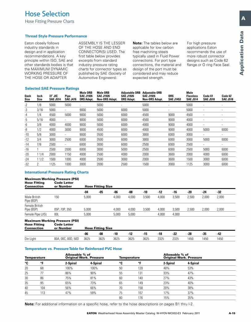
Eaton closely follows industry standards in design and in application recommendations. A key principle within ISO, SAE and other standards bodies is that the MAXIMUM DYNAMIC WORKING PRESSURE OF THE HOSE OR ADAPTER
ASSEMBLY IS THE LESSER OF THE HOSE AND END CONNECTOR(S) USED. The first table below provides excerpts from standard industry pressure rating charts for connector types as published by SAE (Society of Automotive Engineers).
Note: The tables below are applicable for low carbon free machining steels typically used in Fluid Power connections. For port type connections, the material and design of the port must be considered and may reduce expected strength.
For high pressure applications Eaton recommends the use of more robust connector designs such as Code 62 flange or O ring Face Seal.
Hose SelectionHose Fitting Pressure Charts
Maximum Working Pressure (PSI) Hose Fitting Code Letter Connection or Number Hose Fitting Size
-04 -05 -06 -08 -10 -12 -16 -20 -24 -32male british 150 5,000 4,000 4,000 3,500 4,000 3,500 2,500 2,000 2,000 pipe (bsp)female british pipe (bsp) 05p, 70p, 350 5,000 4,000 4,000 3,500 4,000 3,500 2,500 2,000 2,000female pipe (jis) 00l 5,000 5,000 5,000 4,000 4,000
Maximum Working Pressure (PSI)Hose Fitting Code Letter Connection or Number Hose Fitting Size
-06 -08 -10 -12 -15 -18 -22 -28 -35 -42din light 00a, 00c, 00d, 50d 3625 3625 3625 3625 3625 2325 2325 1450 1450 1450
Temperature vs. Pressure Table for Reinforced PVC Hose Allowable % of Allowable % of Temperature Original Work. Pressure Temperature Original Work. Pressure
°C °F 2-Spiral 4-Spiral °C °F 2-Spiral 4-Spiral20 68 100% 100% 50 120 40% 53%25 77 86% 90% 55 131 33% 47%30 86 75% 81% 60 140 27% 43%35 95 65% 73% 65 149 23% 40%40 104 56% 66% 70 158 20% 38%45 113 47% 59% 75 167 17% 37% 80 176 15% 35%
Note: For additional information on a specific hose, refer to the hose descriptions on pages B1 thru I-2.
Thread Style Pressure Performance
Selected SAE Pressure Ratings
International Pressure Rating Charts
MaleORB MaleORB AdjustableORB AdjustableORB MaleDash Inch 37˚JIC Pipe SAEJ1926 SAEJ1926 SAEJ1926 SAEJ1926 ORS Flareless Code61 Code62Size Size SAEJ514 SAEJ476 ORSAdapt. Non-ORSAdapt. ORSAdapt. Non-ORSAdapt. SAEJ1453 SAEJ514 SAEJ518 SAEJ518
-2 1/8 5000 5000 - 5000 - 5000 - 5000 - --3 3/16 5000 - 9000 5000 6000 5000 - 5000 - --4 1/4 4500 5000 9000 5000 6000 4500 9000 4500 - --5 5/16 4000 - 9000 5000 6000 4500 9000 4000 - --6 3/8 4000 4000 9000 5000 6000 4000 9000 4000 - --8 1/2 4000 3000 9000 4500 6000 4000 9000 4000 5000 6000-10 5/8 3000 - 9000 3500 6000 3000 6000 3000 - --12 3/4 3000 2500 6000 3500 6000 3000 6000 3000 5000 6000-14 7/8 2500 - 6000 3000 6000 2500 6000 2500 - --16 1 2500 2000 6000 3000 5000 2500 6000 2500 5000 6000-20 1 1/4 2000 1150 4000 2500 4000 2000 3600 2000 4000 6000-24 1 1/2 1500 1000 4000 2500 3000 2000 3600 1500 3000 6000-32 2 1125 1000 3000 2000 2500 1500 3000 1125 3000 6000

EATON Weatherhead Hose Assembly Master Catalog W-HYOV-MC002-E3 February 2011A-16
A
B
C
D
E
F
G
H
I
J
K
L
M
N
O
Ap
plicatio
n D
ata
Hose SelectionHose Fitting Pressure Charts
Dynamic Operating Pressure – Dynamic operating conditions refers to cyclic pressure impulses, usually considered to be from near zero to the highest system pressure. Hydraulic standards typically represent these as square waves and expect a component to handle on the order of 200,000 to well over one million such cycles with a burst:operating safety factor of 4:1. The above charts are created with Dynamic applications in mind. Most industrial and mobile hydraulic systems fit the dynamic operating pressure profile, for example hydraulic work circuits on construction equipment or on injection molding equipment.
Static Operating Pressure –Static operating conditions typically range from zero to operating pressure, but with far fewer cycles expected for the system life – perhaps 30,000 to 50,000 cycles and sharp pressure spikes are not expected, allowing a burst:operating safety factor of 3:1 or less. For static operating conditions, the Eaton ratings above can be safely increased by 25-30%. For example, a 3000 psi dynamic rated hose might be used in a 4000 psi static pressure application. Typical examples of static applications are water blast and hydraulic jacking.
Materials – The above tables represent performance using common low carbon steel material. Other materials and their characteristics influence these ratings. Medium carbon steels or heat treated materials can support higher working pressures. Conversely non-ferrous materials such as aluminum or brass will have reduced capability – as much as 50%, or less, pressure handling capability. It is important to consider material properties in designing a system to ensure pressure rating compatibility of all materials.
Design & Application – Eaton’s Fluid Conveyance engineering and support teams have many decades of experience in designing, manufacturing and servicing hydraulic and other fluid conveyance systems globally. Eaton’s product line is designed as a comprehensive collection of hose, fittings, connectors, couplings and accessories that allow a system designer to select components to complete a fluid power system or a service technician to replace a component with confidence. The individual product specifications, the above pressure ratings and other technical information are intended as supporting guidelines for system design and service needs and are not to be construed as a guarantee of performance of the system or of individual Eaton components. Eaton provides comprehensive technical support so please call with questions about pressure needs not covered by these charts or for specific application support.
With higher pressures it is critical to know the construction materials and manufacturing method to ensure performance. When all
components in a system are Eaton supplied, for example an Eaton hose fitting is mated with an Eaton adapter or tube fitting, the combination may
be used at higher pressures with confidence, These higher ratings are noted in the chart below. MAXIMUM DYNAMIC WORKING
PRESSURE OF THE HOSE OR ADAPTER ASSEMBLY IS THE LESSER OF THE HOSE AND END CONNECTOR(S) USED.
All Eaton Components
All Eaton Pressure Ratings1
Notes:
1) These ratings are based on both brazed and one piece construction, one-piece pressures could be increased. Please contact Eaton in these situations.
2) This rating is for thin walled adapters or fittings, the use of manifolds or oversized female ports would allow full rated male pressures.
MaleORB MaleORB AdjustableORB AdjustableORBDash Inch 37˚ Male Female ORS Non-ORS ORS Non-ORS Male Size Size JIC Pipe Pipe2 Adapters Adapters Adapters Adapters ORS Flareless Code61 Code62 STC
-2 1/8 - 10000 6000 - 5000 - 5000 - 5000 - - --3 3/16 - - - 9000 5000 6000 5000 - 5000 - - --4 1/4 7000 9500 5000 9000 5000 6000 4500 9000 4500 - - 6000-5 5/16 7000 - - 9000 5000 6000 4500 - 4000 - - --6 3/8 5000 8000 4000 9000 5000 6000 4000 9000 4000 - - 5000-8 1/2 4000 6000 4000 9000 4500 6000 4000 9000 4000 5000 6000 4250-10 5/8 3800 - - 9000 3500 6000 3000 9000 3000 - - 4000-12 3/4 3300 5000 3500 6000 3500 6000 3000 6000 3000 5000 6000 4000-14 7/8 - - - 6000 3000 6000 2500 - 2500 - - --16 1 3500 4000 3000 6000 3000 5000 2500 6000 2500 5000 6000 4000-20 1 1/4 2500 3000 2000 4000 2500 4000 2000 4500 2000 4000 6000 --24 1 1/2 2100 2000 1500 4000 2500 3000 2000 4000 1500 3000 6000 --32 2 1750 2000 1500 3000 2000 2500 1500 3000 1125 3000 6000 -

EATON Weatherhead Hose Assembly Master Catalog W-HYOV-MC002-E3 February 2011 A-17
A
B
C
D
E
F
G
H
I
J
K
L
M
N
O
Ap
plica
tio
n D
ata
Fitting Thread Size Comparison Chart
The male connections have (Male unified thread class 2 fit) UN-2A specification threads and the female connections have (Female unified thread class 2 fit) UN-2B specification threads. The exceptions are male and female pipe threads.
Tube Fittings
There are four basic types of tube fittings: Flare, Flareless, Straight Thread O-ring, and Flat Face O-ring Seal (FOR-SEAL™). Tube fittings seal in two ways. Flare and Flareless fittings use metal to metal contact joints. Straight Thread O-ring and Flat Face O-ring fittings use a rubber O-ring. Where extreme vibration is present, use Flareless, Straight Thread or Flat Face O-ring Seal fittings.
Sizing
For accuracy, it is recommended the male thread be measured. Measure the outside diameter. For our example use 7/16" Next measure the threads per inch – use 20. Our fitting size measures 7/16-20. Refer to the thread chart on this page for appropriate tube size and illustration.see page n-60 for thread measuring Kits.
Pipe Fittings
The American Society of Automotive Engineers in cooperation with industry set up a standard for improvement in pipe threads. This improvement is known as the Dryseal Pipe Thread. All Weatherhead pipe threads are American Standard Taper Dryseal Pipe Threads (NPTF). The metal to metal seal is formed by contact at the thread crest and root.
Nominal pipe sizes do not agree with either the I.D., O.D., or thread sizes. To determine pipe size (up to 1-1/4") measure the diameter of the threads and subtract 1/4" For example, subtract 1/4" from a 1" pipe to obtain the nominal pipe size of 3/4".
Pipe sizes can also be given in ‘dash numbers.’ A dash number is always the numerator of an inch over 16th. For instance, if the pipe O.D. measures 1/2" that would be converted to 16ths (8/16), but be written as -8.
37° Flare Ermeto® Straight Thread 45° InvertedSize Pipe FOR-SEAL® Flare-Twin® 7000 Series O-ring SAE Flare Flare
1/8 1/8-27 — 5/16-24 5/16-24 5/16-24 5/16-24 5/16-283/16 — — 3/8-24 3/8-24 3/8-24 3/8-24 3/8-241/4 1/4-18 9/16-18 7/16-20 7/16-20 7/16-20 7/16-20 7/16-245/16 — — 1/2-20 1/2-20 1/2-20 1/2-20 1/2-203/8 3/8-18 11/16-16 9/16-18 9/16-18 9/16-18 5/8-18 5/8-187/16 — — — — — 11/16-16 11/16-181/2 1/2-14 13/16-16 3/4-16 3/4-16 3/4-16 3/4-16 3/4-185/8 — 1-14 7/8-14 7/8-14 7/8-14 7/8-14 7/8-183/4 3/4-14 1-3/16–12 1-1/16–12 1-1/16–12 1-1/16–12 1-1/16–14 1-1/16–167/8 — — 1-3/16–12 1-3/16–12 1-3/16–12 — 1-3/16–161 1–11-1/2 1-7/16–12 1-5/16–12 1-5/16–12 1-5/16–12 — 1-5/16–161 1/4 1-1/4–11-1/2 1-11/16–12 1-5/8–12 1-5/8–12 1-5/8–12 — —1 1/2 1-1/2–11-1/2 2-12 1-7/8–12 1-7/8–12 1-7/8–12 — —2 2–11-1/2 — 2-1/2–12 2-1/2–12 2-1/2–12 — —2 1/2 2-1/2–8 — 3-12 — — — —3 3-8 — 3-1/2–12 — — — —
Fitting Identification
1/14// "3/3 8// "1/12// "

EATON Weatherhead Hose Assembly Master Catalog W-HYOV-MC002-E3 February 2011A-18
A
B
C
D
E
F
G
H
I
J
K
L
M
N
O
Ap
plicatio
n D
ata
Identifying metric, or non-USA, threaded connections is similar to identifying the connections that have been commonly used
in the United States. The following text covers how to identify the different styles of metric connections offered by Eaton.
BSPP & BSPT Thread Chart BSP Thread Size 1/8-28 1/4-19 3/8-19 1/2-14 5/8-14 3/4-14 1-11 1-1/4–11 1-1/2–11 2-11
male thread 9.72 13.16 16.66 20.96 22.91 26.44 33.25 41.91 47.80 59.51 diameter (.375) (.518) (.656) (.825) (.902) (1.041) (1.309) (1.650) (1.882) (2.347)female thread 8.73 11.66 15.37 18.90 20.85 24.38 30.61 39.24 45.24 55.94 diameter (.343) (.459) (.605) (.744) (.821) (.960) (1.205) (1.545) (1.781) (2.242)pitch .91 1.34 1.34 1.81 1.81 1.81 2.31 2.31 2.31 2.31 (.036) (.053) (.053) (.071) (.071) (.071) (.091) (.091) (.091) (.091)
Figure 4a. Dimension Note: mm (in)
Note:BS British Standards Institution
ISO International Standards Organization
DIN Deutsche Industrie Norme
To identify metric connections, you will need instruments that can accurately measure thread inside and outside diameters, thread pitch and fitting seat angles. The TA-1002 Thread Measuring Guide and Tool Kit is a basic kit that will help you in identifying most of the connections you will be encountering on imported equipment.
Parallel and Tapered Threads
The first step in identifying thread forms is to determine if the thread is parallel or tapered. Parallel threads are not used for sealing fluids. Sealing is achieved by an elastomeric O-ring, metal seal, machined ring into the hex itself or a seat machined into the end of the fitting. This style is similar to straight thread O-ring port connections where the threads are used for retention of the sealing method against a machine port. Parallel threads can be determined by laying a straight edge along the threads. If the threads are parallel to the center line of the fitting, then the fitting has parallel threads. See Figure 1.
Tapered threads seat by the interference caused by the male and female threads. These threads create a pressure-tight joint by metal deformation when they are tightened. Sealants on the threads are commonly used in this style of connection. Laying a straight edge on the threads, compare this line with the center line of the fitting. If this line tapers slightly away from the center line, then the threads are tapered. See Figure 2.
British Pipe Threads
There are two forms of British Standard Pipe Threads that are used in the world today. They are BSPP (British Standard Pipe Parallel) and BSPT (British Standard Pipe Tapered). The BSPT male thread mates with the female BSPT thread similar to an NPTF connection. The 30° BSPP male adapters connect to a female BSPP thread with a 30° cone. This style is comparable to an NPSM swivel style. These threads are almost identical to the NPTF Pipe Thread except for the flank angle. This angle is 55° versus 60° on the NPTF. See Figure 3. Because of this difference, the two forms are NOT interchangeable.
Threads
The thread forms and their corresponding specifications listed below are used on all of the metric styles of connections which will be discussed later. These cover the basic forms of the threads but not the style of connection.
Thread Type Specifications
british parallel pipe threads bs 2779, iso/r 228british taper pipe threads bs 21, iso/r 7metric parallel threads din 3852, iso/r 6149metric taper threads din 3852
Parallel Threads ('G') Tapered Threads (‘R’)
Figure1. Figure2.
Fitting Identification
Figure3.
BSPP BSPT NPTF
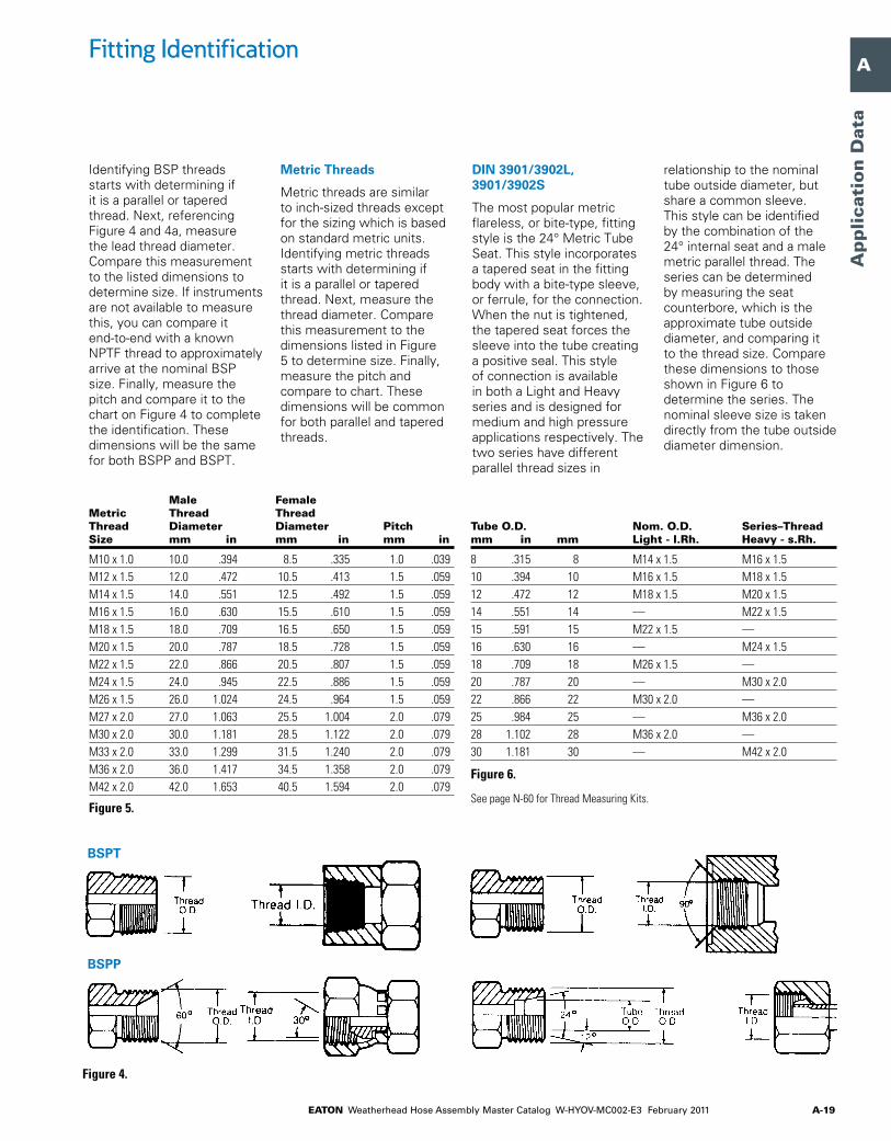
EATON Weatherhead Hose Assembly Master Catalog W-HYOV-MC002-E3 February 2011 A-19
A
B
C
D
E
F
G
H
I
J
K
L
M
N
O
Ap
plica
tio
n D
ata
Tube O.D. Nom. O.D. Series–Thread mm in mm Light - l.Rh. Heavy - s.Rh.
8 .315 8 m14 x 1.5 m16 x 1.510 .394 10 m16 x 1.5 m18 x 1.512 .472 12 m18 x 1.5 m20 x 1.514 .551 14 — m22 x 1.515 .591 15 m22 x 1.5 —16 .630 16 — m24 x 1.518 .709 18 m26 x 1.5 —20 .787 20 — m30 x 2.022 .866 22 m30 x 2.0 —25 .984 25 — m36 x 2.028 1.102 28 m36 x 2.0 —30 1.181 30 — m42 x 2.0
Figure6.
see page n-60 for thread measuring Kits.
Identifying BSP threads starts with determining if it is a parallel or tapered thread. Next, referencing Figure 4 and 4a, measure the lead thread diameter. Compare this measurement to the listed dimensions to determine size. If instruments are not available to measure this, you can compare it end-to-end with a known NPTF thread to approximately arrive at the nominal BSP size. Finally, measure the pitch and compare it to the chart on Figure 4 to complete the identification. These dimensions will be the same for both BSPP and BSPT.
Metric Threads
Metric threads are similar to inch-sized threads except for the sizing which is based on standard metric units. Identifying metric threads starts with determining if it is a parallel or tapered thread. Next, measure the thread diameter. Compare this measurement to the dimensions listed in Figure 5 to determine size. Finally, measure the pitch and compare to chart. These dimensions will be common for both parallel and tapered threads.
DIN 3901/3902L, 3901/3902S
The most popular metric flareless, or bite-type, fitting style is the 24° Metric Tube Seat. This style incorporates a tapered seat in the fitting body with a bite-type sleeve, or ferrule, for the connection. When the nut is tightened, the tapered seat forces the sleeve into the tube creating a positive seal. This style of connection is available in both a Light and Heavy series and is designed for medium and high pressure applications respectively. The two series have different parallel thread sizes in
relationship to the nominal tube outside diameter, but share a common sleeve. This style can be identified by the combination of the 24° internal seat and a male metric parallel thread. The series can be determined by measuring the seat counterbore, which is the approximate tube outside diameter, and comparing it to the thread size. Compare these dimensions to those shown in Figure 6 to determine the series. The nominal sleeve size is taken directly from the tube outside diameter dimension.
BSPT
BSPP
Figure4.
Male Female Metric Thread Thread Thread Diameter Diameter Pitch Size mm in mm in mm in
m10 x 1.0 10.0 .394 8.5 .335 1.0 .039m12 x 1.5 12.0 .472 10.5 .413 1.5 .059m14 x 1.5 14.0 .551 12.5 .492 1.5 .059m16 x 1.5 16.0 .630 15.5 .610 1.5 .059m18 x 1.5 18.0 .709 16.5 .650 1.5 .059m20 x 1.5 20.0 .787 18.5 .728 1.5 .059m22 x 1.5 22.0 .866 20.5 .807 1.5 .059m24 x 1.5 24.0 .945 22.5 .886 1.5 .059m26 x 1.5 26.0 1.024 24.5 .964 1.5 .059m27 x 2.0 27.0 1.063 25.5 1.004 2.0 .079m30 x 2.0 30.0 1.181 28.5 1.122 2.0 .079m33 x 2.0 33.0 1.299 31.5 1.240 2.0 .079m36 x 2.0 36.0 1.417 34.5 1.358 2.0 .079m42 x 2.0 42.0 1.653 40.5 1.594 2.0 .079
Fitting Identification
Figure5.
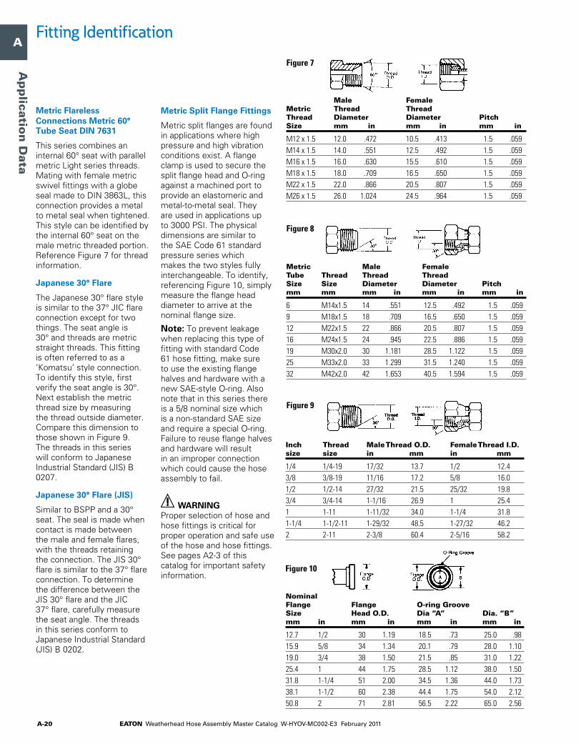
EATON Weatherhead Hose Assembly Master Catalog W-HYOV-MC002-E3 February 2011A-20
A
B
C
D
E
F
G
H
I
J
K
L
M
N
O
Ap
plicatio
n D
ata
Metric Flareless Connections Metric 60° Tube Seat DIN 7631
This series combines an internal 60° seat with parallel metric Light series threads. Mating with female metric swivel fittings with a globe seal made to DIN 3863L, this connection provides a metal to metal seal when tightened. This style can be identified by the internal 60° seat on the male metric threaded portion. Reference Figure 7 for thread information.
Japanese 30° Flare
The Japanese 30° flare style is similar to the 37° JIC flare connection except for two things. The seat angle is 30° and threads are metric straight threads. This fitting is often referred to as a ‘Komatsu’ style connection. To identify this style, first verify the seat angle is 30°. Next establish the metric thread size by measuring the thread outside diameter. Compare this dimension to those shown in Figure 9. The threads in this series will conform to Japanese Industrial Standard (JIS) B 0207.
Japanese 30° Flare (JIS)
Similar to BSPP and a 30° seat. The seal is made when contact is made between the male and female flares, with the threads retaining the connection. The JIS 30° flare is similar to the 37° flare connection. To determine the difference between the JIS 30° flare and the JIC 37° flare, carefully measure the seat angle. The threads in this series conform to Japanese Industrial Standard (JIS) B 0202.
Metric Split Flange Fittings
Metric split flanges are found in applications where high pressure and high vibration conditions exist. A flange clamp is used to secure the split flange head and O-ring against a machined port to provide an elastomeric and metal-to-metal seal. They are used in applications up to 3000 PSI. The physical dimensions are similar to the SAE Code 61 standard pressure series which makes the two styles fully interchangeable. To identify, referencing Figure 10, simply measure the flange head diameter to arrive at the nominal flange size.
Note: To prevent leakage when replacing this type of fitting with standard Code 61 hose fitting, make sure to use the existing flange halves and hardware with a new SAE-style O-ring. Also note that in this series there is a 5/8 nominal size which is a non-standard SAE size and require a special O-ring. Failure to reuse flange halves and hardware will result in an improper connection which could cause the hose assembly to fail.
WARNINGProper selection of hose and hose fittings is critical for proper operation and safe use of the hose and hose fittings. See pages A2-3 of this catalog for important safety information.
Nominal Flange Flange O-ring Groove Size Head O.D. Dia “A” Dia. “B” mm in mm in mm in mm in
12.7 1/2 30 1.19 18.5 .73 25.0 .9815.9 5/8 34 1.34 20.1 .79 28.0 1.1019.0 3/4 38 1.50 21.5 .85 31.0 1.2225.4 1 44 1.75 28.5 1.12 38.0 1.5031.8 1-1/4 51 2.00 34.5 1.36 44.0 1.7338.1 1-1/2 60 2.38 44.4 1.75 54.0 2.1250.8 2 71 2.81 56.5 2.22 65.0 2.56
Inch Thread Male Thread O.D. Female Thread I.D. size size in mm in mm
1/4 1/4-19 17/32 13.7 1/2 12.43/8 3/8-19 11/16 17.2 5/8 16.01/2 1/2-14 27/32 21.5 25/32 19.83/4 3/4-14 1-1/16 26.9 1 25.41 1-11 1-11/32 34.0 1-1/4 31.81-1/4 1-1/2-11 1-29/32 48.5 1-27/32 46.22 2-11 2-3/8 60.4 2-5/16 58.2
Metric Male Female Tube Thread Thread Thread Size Size Diameter Diameter Pitch mm mm mm in mm in mm in
6 m14x1.5 14 .551 12.5 .492 1.5 .0599 m18x1.5 18 .709 16.5 .650 1.5 .05912 m22x1.5 22 .866 20.5 .807 1.5 .05916 m24x1.5 24 .945 22.5 .886 1.5 .05919 m30x2.0 30 1.181 28.5 1.122 1.5 .05925 m33x2.0 33 1.299 31.5 1.240 1.5 .05932 m42x2.0 42 1.653 40.5 1.594 1.5 .059
Male Female Metric Thread Thread Thread Diameter Diameter Pitch Size mm in mm in mm in
m12 x 1.5 12.0 .472 10.5 .413 1.5 .059m14 x 1.5 14.0 .551 12.5 .492 1.5 .059m16 x 1.5 16.0 .630 15.5 .610 1.5 .059m18 x 1.5 18.0 .709 16.5 .650 1.5 .059m22 x 1.5 22.0 .866 20.5 .807 1.5 .059m26 x 1.5 26.0 1.024 24.5 .964 1.5 .059
Fitting Identification
Figure7
Figure8
Figure9
Figure10

EATON Weatherhead Hose Assembly Master Catalog W-HYOV-MC002-E3 February 2011 A-21
A
B
C
D
E
F
G
H
I
J
K
L
M
N
O
Ap
plica
tio
n D
ata
Hose
1. Weatherhead hose is generally designated with the letter ‘H.’*
2. Each hose is assigned a three or four digit base number from 001-9999, i.e., H069, H425, H470, H571.
3. The last two digits indicate inside hose diameter (I.D.) in sixteenths of an inch. In the example used above 08 is equal to 8/16” – or 1/2” I.D. hose.
Exceptions: H059, H069, H166, H169, H213, H229, H239, H366, H429, H569 and H757. The I.D. sizes of these hose de-viate somewhat from the above standard. The sizing method used on these hoses is based on deducting twice the wall thickness from the O.D. of the connecting tubing to determine the I.D. of the hose. In other words, match the inside diam-eters rather than the dash sizes when going from tubing to hose. See example 1.
Table 1 shows standard hose size and H069 type hose sizes and dash numbers. Wherever these hoses are listed in this catalog, the size is listed and the dash number is the last two digits of the Catalog Number.
Examples: Actual Nominal Tubing Tubing Hose I.D. Hose I.D. I.D. O.D.
h06906 5/16 3/8 5/16 3/8h06910 1/2 5/8 1/2 5/8
Table 1 – Catalog Numbers for Hose Sizes Standard H069 Type Actual Catalog Catalog Hose I.D. Number Numbers
3/16 03 041/4 04 055/16 05 063/8 0613/32 087/16 071/2 08 105/8 10 123/4 127/8 161 161-1/8 201-1/4 201-3/8 241-1/2 241-13/16 322 322-3/8 403 48
H 425 08
1 2 3
Numbering Systems

EATON Weatherhead Hose Assembly Master Catalog W-HYOV-MC002-E3 February 2011A-22
A
B
C
D
E
F
G
H
I
J
K
L
M
N
O
Ap
plicatio
n D
ata
Hose Fittings
Every type of Weatherhead hose fitting is designed to fit a certain group of hose with limiting dimensions and tolerances. For your convenience the hoses used on each fitting style are indicated in the hose fitting catalog listings.
Crimp
1. The first two digits indicate hose size (I.D.) in sixteenths of an inch. The exceptions to this are the spiral and truck hose. Spiral hose fittings use the hose base number as a prefix to the size. Example: 47012E. Truck hose fittings use the base number 069 as a prefix to the size. Example: 06908E. Refer to the top of the catalog page where these hose fittings are detailed for recommended hose types.
2. Hose fitting type and material. Refer to Table 2. This letter is always followed by a dash.
3. The first number or letter indicates the style of the end connection. See individual hose fitting catalog listings or refer to the hose fitting configuration chart on pages A-23-28
4. The last two digits indicate the size of the end connection in sixteenths of an inch. Refer to individual catalog listing for metric and specialty ends.
Hose Assemblies
Catalog numbers for hose assemblies are basically the same as hose fittings, except both the ends must be specified as well as the overall length. This process is detailed below:
1. Type of desired hose (see hose selection guide pages A-4-9 or individual hose listings).
2. Hose size (I.D.) in sixteenths of an inch (04 = 4/16” = 1/4”). Exception: 13/32” I.D. hose.
3. End style and material. Refer to Table 2 (above).
4-5. Style and size of each hose fitting. Refer to the individual hose fitting catalog listings or the Hose Fitting Configuration Chart on pages A-23-28 for available styles and sizes. Example: P04 Male Straight Thread O-ring 1/4”, 604 SAE 37° Female Swivel 1/4.”
6. Length of assembly. The first three digits specify a length in inches. The last two digits are for fractions of an inch expressed in decimal hundredths (01250 = 12 1/2”).
Table 2 – Standard Hose Fitting and Material CodeCode Coupling Letter Type Material
b field attachable brassc crimped brassd field attachable* steel*E crimp steelK clamp type steeln field attachable steelp crimp brasss crimp stainless steelt field attachable* brassu crimp steelZ crimp steel
*high flow hose assemblies
Field Attachable
1. Description of basic hose. The exceptions are the 247 series and clamp type ends. These ends are designed for use with a variety of hose types. Refer to the top of the catalog page where these hose fittings are detailed for recommended hose types.
2. Hose size (I.D.) in sixteenths of an inch, or as shown in Table 1.
3. Hose fitting type and material. Refer to Table 2. This letter is always followed by a dash.
4. The first number or letter indicates the style of the end connection. See individual hose fitting catalog listings or refer to the hose fitting configuration chart on pages A-23-28.
5. The last two digits indicate the size of the end connection in sixteenths of an inch. Refer to individual catalog listing for metric and specialty ends.
Note: To determine the hose only length when making a hose assembly, subtract each hose fitting cut-off factor from the overall hose assembly length. Please see the individual hose fitting listings for cut-off factor information.
To determine Hose Cut-Off Factors reference page A-30.
4251 2
085
58N-23 4
425
1
04
2
U-
3
P04
4
604
5
01250
6
081
U-24
582 3
Numbering Systems

EATON Weatherhead Hose Assembly Master Catalog W-HYOV-MC002-E3 February 2011 A-23
A
B
C
D
E
F
G
H
I
J
K
L
M
N
O
Ap
plica
tio
n D
ata
The chart to the side is designed to offer quick identification of Weatherhead hose fitting series. Included in this chart are: base numbers, descriptions, hose fitting series, and page number in which the configuration appears. Catalog numbers may be derived by adding the size in sixteenths of an inch to the base.
Example: 100 series 3/4” male pipe rigid. 3/4” = 12/16” thus 100 + 12 = 112.
Part
#
Suf
fixH
ose
Fit
tin
gS
tyle
009 ‘B’
057 ‘B’
100 ‘B’
105 ‘B’
057 ‘P’
338 ‘B’
069 ‘D’
'E’
069 ‘E’
336 ‘E’
470 ‘E’
757 ‘E’
'K’
039 ‘K’
104 ‘N’
213 ‘N’
247 ‘N’
425 ‘N’
436 ‘N’
229 ‘P’
265 ‘P’
338 ‘P’
'S’
'U’
430 ‘U’
'Z’
4SP/6SP
00A
Mal
e D
IN (
Lig
ht)
Rig
idJ-
38J-
89
00C
Fe
mal
e D
IN (
Lig
ht)
Sw
ivel
J-18
J-44
J-57
J-88
00D
Fem
ale
DIN
45°
(Li
gh
t)S
wiv
elJ-
48J-
88
00E
Fem
ale
Din
24°
45°
Tube
El
bow
Sw
ivel
J-89
J-10
0
00F
Mal
e D
IN (
Hea
vy)
Rig
idJ-
17J-
39J-
90
00K
Fem
ale
30°
Flar
e (K
om
atsu
)S
wiv
elJ-
11J-
44J-
58J-
87
00L
Fem
ale
JIS
30°
Fla
reS
wiv
elJ-
4J-
45J-
87
00P
Fem
ale
Flat
Fac
e B
SP
PS
wiv
elJ-
46
00S
Rea
dy
Lok®
Rig
idJ-
46J-
58
0PW
Pre
ssu
re W
ash
erS
wiv
elJ-
85
30T
Str
aig
ht T
ub
e-M
etri
cR
igid
J-47
J-84
40P
Bri
t. S
td. 6
0° C
one
Para
llel
Fem
ale
Pipe
45°
Sw
ivel
J-19
J-50
J-59
J-86
J-98
50C
Fem
ale
DIN
(H
eavy
)S
wiv
elJ-
44J-
57J-
89J-
100
50D
Fem
ale
DIN
90°
(Li
gh
t)S
wiv
elJ-
52J-
88
50E
Fem
ale
DIN
90°
(H
eavy
)S
wiv
elJ-
52J-
90J-
100
70P
Bri
t. S
td 6
0° C
on
e Pa
ralle
l Fe
mal
e P
ipe
90°
Sw
ivel
J-7
J-21
J-53
J-62
J-86
J-98
050
Fem
ale
Str
aig
ht
Pip
eS
wiv
elJ-
14J-
43J-
69
100
Mal
e P
ipe
Rig
idK-
2K-
3K-
5K-
8K-
12J-
2J-
9J-
13J-
17K-
14K-
15K-
16K-
19K-
22K-
27K-
30J-
32J-
34J-
36J-
37J-
55J-
68J-
99
150
Mal
e P
ipe,
Bri
tish
S
tan
dar
d Ta
per
edR
igid
J-38
J-86
200
Fem
ale
Pip
eR
igid
K-8
J-14
J-32
J-42
J-69
250
Fem
ale
Pip
eS
wiv
elK-
6K-
28J-
43J-
69
Numbering Systems
DenotesColl-O-CrimpHoseFittings
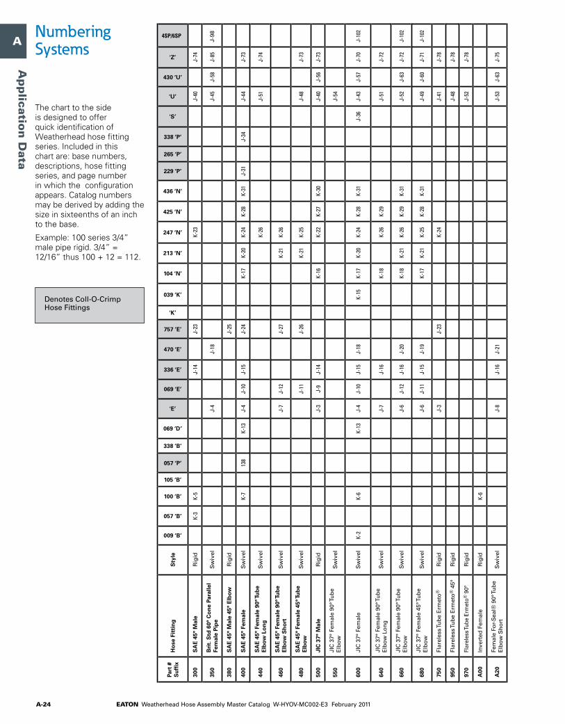
EATON Weatherhead Hose Assembly Master Catalog W-HYOV-MC002-E3 February 2011A-24
A
B
C
D
E
F
G
H
I
J
K
L
M
N
O
Ap
plicatio
n D
ata
The chart to the side is designed to offer quick identification of Weatherhead hose fitting series. Included in this chart are: base numbers, descriptions, hose fitting series, and page number in which the configuration appears. Catalog numbers may be derived by adding the size in sixteenths of an inch to the base.
Example: 100 series 3/4” male pipe rigid. 3/4” = 12/16” thus 100 + 12 = 112.
Numbering Systems
DenotesColl-O-CrimpHoseFittings
Part
#
Suf
fixH
ose
Fit
tin
gS
tyle
009 ‘B’
057 ‘B’
100 ‘B’
105 ‘B’
057 ‘P’
338 ‘B’
069 ‘D’
'E’
069 ‘E’
336 ‘E’
470 ‘E’
757 ‘E’
'K’
039 ‘K’
104 ‘N’
213 ‘N’
247 ‘N’
425 ‘N’
436 ‘N’
229 ‘P’
265 ‘P’
338 ‘P’
'S’
'U’
430 ‘U’
'Z’
4SP/6SP
300
SA
E 4
5° M
ale
Rig
idK-
3K-
5J-
14J-
23K-
23J-
40J-
74
350
Bri
t. S
td 6
0° C
on
e Pa
ralle
l Fe
mal
e P
ipe
Sw
ivel
J-4
J-18
J-45
J-58
J-85
J-98
380
SA
E 4
5° M
ale
45°
Elb
owR
igid
J-25
400
SA
E 4
5° F
emal
eS
wiv
elK-
713
8K-
13J-
4J-
10J-
15J-
24K-
17K-
20K-
24K-
28K-
31J-
31J-
34J-
44J-
73
440
SA
E 4
5° F
emal
e 90
° Tu
be
Elb
ow L
on
gS
wiv
elK-
26J-
51J-
74
460
SA
E 4
5° F
emal
e 90
° Tu
be
Elb
ow S
ho
rtS
wiv
elJ-
7J-
12J-
27K-
21K-
26
480
SA
E 4
5° F
emal
e 45
° Tu
be
Elb
owS
wiv
elJ-
11J-
26K-
21K-
25J-
48J-
73
500
JIC
37°
Mal
eR
igid
J-3
J-9
J-14
K-16
K-22
K-27
K-30
J-40
J-56
J-73
550
JIC
37°
Fem
ale
90°T
ub
eE
lbo
wS
wiv
elJ-
54
600
JIC
37°
Fem
ale
Sw
ivel
K-2
K-6
K-13
J-4
J-10
J-15
J-18
K-15
K-17
K-20
K-24
K-28
K-31
J-36
J-43
J-57
J-70
J-10
2
640
JIC
37°
Fem
ale
90°T
ub
eE
lbo
wL
on
gS
wiv
elJ-
7J-
16K-
18K-
26K-
29J-
51J-
72
660
JIC
37°
Fem
ale
90°T
ub
eE
lbo
wS
wiv
elJ-
6J-
12J-
16J-
20K-
18K-
21K-
26K-
29K-
31J-
52J-
63J-
72J-
102
680
JIC
37°
Fem
ale
45°T
ub
eE
lbo
wS
wiv
elJ-
6J-
11J-
15J-
19K-
17K-
21K-
25K-
28K-
31J-
49J-
60J-
71J-
102
750
Flar
eles
sTu
be
Erm
eto
®R
igid
J-3
J-23
K-24
J-41
J-78
950
Flar
eles
sTu
be
Erm
eto
®4
5°R
igid
J-48
J-78
970
Flar
eles
sTub
eEr
met
o®9
0°R
igid
J-52
J-78
A00
Inve
rted
Fem
ale
Rig
idK-
6
A20
Fem
ale
For-
Sea
l®9
0°T
ub
eE
lbo
wS
ho
rtS
wiv
elJ-
8J-
16J-
21J-
53J-
63J-
75
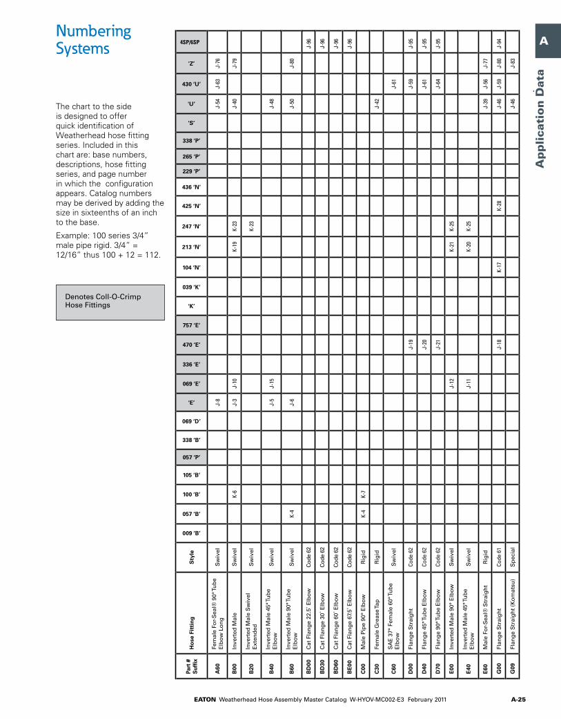
EATON Weatherhead Hose Assembly Master Catalog W-HYOV-MC002-E3 February 2011 A-25
A
B
C
D
E
F
G
H
I
J
K
L
M
N
O
Ap
plica
tio
n D
ata
Part
#
Suf
fixH
ose
Fit
tin
gS
tyle
009 ‘B’
057 ‘B’
100 ‘B’
105 ‘B’
057 ‘P’
338 ‘B’
069 ‘D’
'E’
069 ‘E’
336 ‘E’
470 ‘E’
757 ‘E’
'K’
039 ‘K’
104 ‘N’
213 ‘N’
247 ‘N’
425 ‘N’
436 ‘N’
229 ‘P’
265 ‘P’
338 ‘P’
'S’
'U’
430 ‘U’
'Z’
4SP/6SP
A60
Fem
ale
For-
Sea
l®9
0°T
ub
eE
lbo
wL
on
gS
wiv
elJ-
8J-
54J-
63J-
76
B00
Inve
rted
Mal
eS
wiv
elK-
6J-
3J-
10K-
19K-
23J-
40J-
79
B20
Inve
rted
Mal
eS
wiv
el
Ext
end
edS
wiv
elK-
23
B40
Inve
rted
Mal
e45
°Tu
be
Elb
ow
Sw
ivel
J-5
J-15
J-48
B60
Inve
rted
Mal
e90
°Tu
be
Elb
ow
Sw
ivel
K-4
J-6
J-50
J-80
BD
00C
atF
lan
ge
22.5
˚Elb
ow
Cod
e62
J-96
BD
30C
atF
lan
ge
30˚E
lbo
wC
ode
62J-
96
BD
60C
atF
lan
ge
60˚E
lbo
wC
ode
62J-
96
BE
00C
atF
lan
ge
67.5
˚Elb
ow
Cod
e62
J-96
C00
Mal
eP
ipe
90°
Elb
ow
Rig
idK-
4K-
7
C30
Fem
ale
Gre
ase
Tap
Rig
idJ-
42
C60
SA
E3
7°F
emal
e60
°Tu
be
Elb
ow
Sw
ivel
J-61
D00
Flan
ge
Str
aig
ht
Code
62
J-19
J-59
J-95
D40
Flan
ge
45°T
ub
eE
lbo
wCo
de6
2J-
20J-
61J-
95
D70
Flan
ge
90°T
ub
eE
lbo
wCo
de6
2J-
21J-
64J-
95
E00
Inve
rted
Mal
e90
°E
lbo
wS
wiv
elJ-
12K-
21K-
25
E40
Inve
rted
Mal
e45
°Tu
be
Elb
ow
Sw
ivel
J-11
K-20
K-25
E60
Mal
eFo
r-S
eal®
Str
aig
ht
Rig
idJ-
39J-
56J-
77
G00
Flan
ge
Str
aig
ht
Code
61
J-18
K-17
K-28
J-46
J-59
J-80
J-94
G09
Flan
ge
Str
aig
ht
(Ko
mat
su)
Sp
ecia
lJ-
46J-
83
The chart to the side is designed to offer quick identification of Weatherhead hose fitting series. Included in this chart are: base numbers, descriptions, hose fitting series, and page number in which the configuration appears. Catalog numbers may be derived by adding the size in sixteenths of an inch to the base.
Example: 100 series 3/4” male pipe rigid. 3/4” = 12/16” thus 100 + 12 = 112.
Numbering Systems
DenotesColl-O-CrimpHoseFittings

EATON Weatherhead Hose Assembly Master Catalog W-HYOV-MC002-E3 February 2011A-26
A
B
C
D
E
F
G
H
I
J
K
L
M
N
O
Ap
plicatio
n D
ata
The chart to the side is designed to offer quick identification of Weatherhead hose fitting series. Included in this chart are: base numbers, descriptions, hose fitting series, and page number in which the configuration appears. Catalog numbers may be derived by adding the size in sixteenths of an inch to the base.
Example: 100 series 3/4” male pipe rigid. 3/4” = 12/16” thus 100 + 12 = 112.
Numbering Systems
DenotesColl-O-CrimpHoseFittings
Part
#
Suf
fixH
ose
Fit
tin
gS
tyle
009 ‘B’
057 ‘B’
100 ‘B’
105 ‘B’
057 ‘P’
338 ‘B’
069 ‘D’
'E’
069 ‘E’
336 ‘E’
470 ‘E’
757 ‘E’
'K’
039 ‘K’
104 ‘N’
213 ‘N’
247 ‘N’
425 ‘N’
436 ‘N’
229 ‘P’
265 ‘P’
338 ‘P’
'S’
'U’
430 ‘U’
'Z’
4SP/6SP
G40
Flan
ge
45°T
ub
eE
lbo
wCo
de6
1J-
20K-
18K-
29J-
49J-
49J-
81J-
94
G69
Flan
ge
45°T
ub
eE
lbo
w
(Ko
mat
su)
Sp
ecia
lJ-
50J-
83
G70
Flan
ge
90°T
ub
eE
lbo
wCo
de6
1J-
21K-
18K-
29J-
54J-
64J-
82J-
94
G99
Flan
ge
90°T
ub
eE
lbo
wS
pec
ial
J-83
H00
Flan
ge
22-1
/2°T
ub
eE
lbo
wCo
de6
1J-
60J-
81
H20
Flan
ge
30°T
ub
eE
lbo
wCo
de6
1J-
60
H50
Flan
ge
60°T
ub
eE
lbo
wCo
de6
1J-
62J-
82
H60
Flan
ge
67-1
/2°T
ub
eE
lbo
wCo
de6
1J-
62
H70
Flan
ge
100°
Tu
be
Elb
ow
Code
61
J-65
H80
Flan
ge
110°
Tu
be
Elb
ow
Code
61
J-65
H90
Flan
ge
135°
Tu
be
Elb
ow
Code
61
J-65
J00
Mal
eP
ipe
Sw
ivel
J-2
J-13
J-34
J-39
J-56
J-68
J33
Fem
ale
For-
Sea
l®9
0°T
ub
eE
lbo
wM
ed.
Sw
ivel
J-53
J-76
J-10
1
J63
Fem
ale
For-
Sea
l®S
trai
gh
tS
wiv
elJ-
101
K00
Flan
ge
Str
aig
ht“
Cat
Fl
ang
e”Co
de6
2J-
96
K30
Flan
ge
45°T
ub
eE
lbo
w
“Cat
Fla
ng
e”Co
de6
2J-
96
K60
Flan
ge
90°T
ub
eE
lbo
w
“Cat
Fla
ng
e”Co
de6
2J-
96
L00
Ban
jo(
Ford
Tra
cto
r)S
pec
ial
J-47
L10
JIC
37°
Fem
ale
30°T
ub
eE
lbo
wS
wiv
elJ-
47J-
71
L40
Mal
e45
°Tu
be
Elb
ow
O
-Rin
gP
ort
Sw
ivel
J-49

EATON Weatherhead Hose Assembly Master Catalog W-HYOV-MC002-E3 February 2011 A-27
A
B
C
D
E
F
G
H
I
J
K
L
M
N
O
Ap
plica
tio
n D
ata
Part
#
Suf
fixH
ose
Fit
tin
gS
tyle
009 ‘B’
057 ‘B’
100 ‘B’
105 ‘B’
057 ‘P’
338 ‘B’
069 ‘D’
'E’
069 ‘E’
336 ‘E’
470 ‘E’
757 ‘E’
'K’
039 ‘K’
104 ‘N’
213 ‘N’
247 ‘N’
425 ‘N’
436 ‘N’
229 ‘P’
265 ‘P’
338 ‘P’
'S’
'U’
430 ‘U’
'Z’
4SP/6SP
G40
Flan
ge
45°T
ub
eE
lbo
wCo
de6
1J-
20K-
18K-
29J-
49J-
49J-
81J-
94
G69
Flan
ge
45°T
ub
eE
lbo
w
(Ko
mat
su)
Sp
ecia
lJ-
50J-
83
G70
Flan
ge
90°T
ub
eE
lbo
wCo
de6
1J-
21K-
18K-
29J-
54J-
64J-
82J-
94
G99
Flan
ge
90°T
ub
eE
lbo
wS
pec
ial
J-83
H00
Flan
ge
22-1
/2°T
ub
eE
lbo
wCo
de6
1J-
60J-
81
H20
Flan
ge
30°T
ub
eE
lbo
wCo
de6
1J-
60
H50
Flan
ge
60°T
ub
eE
lbo
wCo
de6
1J-
62J-
82
H60
Flan
ge
67-1
/2°T
ub
eE
lbo
wCo
de6
1J-
62
H70
Flan
ge
100°
Tu
be
Elb
ow
Code
61
J-65
H80
Flan
ge
110°
Tu
be
Elb
ow
Code
61
J-65
H90
Flan
ge
135°
Tu
be
Elb
ow
Code
61
J-65
J00
Mal
eP
ipe
Sw
ivel
J-2
J-13
J-34
J-39
J-56
J-68
J33
Fem
ale
For-
Sea
l®9
0°T
ub
eE
lbo
wM
ed.
Sw
ivel
J-53
J-76
J-10
1
J63
Fem
ale
For-
Sea
l®S
trai
gh
tS
wiv
elJ-
101
K00
Flan
ge
Str
aig
ht“
Cat
Fl
ang
e”Co
de6
2J-
96
K30
Flan
ge
45°T
ub
eE
lbo
w
“Cat
Fla
ng
e”Co
de6
2J-
96
K60
Flan
ge
90°T
ub
eE
lbo
w
“Cat
Fla
ng
e”Co
de6
2J-
96
L00
Ban
jo(
Ford
Tra
cto
r)S
pec
ial
J-47
L10
JIC
37°
Fem
ale
30°T
ub
eE
lbo
wS
wiv
elJ-
47J-
71
L40
Mal
e45
°Tu
be
Elb
ow
O
-Rin
gP
ort
Sw
ivel
J-49 The chart to the side
is designed to offer quick identification of Weatherhead hose fitting series. Included in this chart are: base numbers, descriptions, hose fitting series, and page number in which the configuration appears. Catalog numbers may be derived by adding the size in sixteenths of an inch to the base.
Example: 100 series 3/4” male pipe rigid. 3/4” = 12/16” thus 100 + 12 = 112.
Numbering Systems
DenotesColl-O-CrimpHoseFittings
Part
#
Suf
fixH
ose
Fit
tin
gS
tyle
009 ‘B’
057 ‘B’
100 ‘B’
105 ‘B’
057 ‘P’
338 ‘B’
069 ‘D’
'E’
069 ‘E’
336 ‘E’
470 ‘E’
757 ‘E’
'K’
039 ‘K’
104 ‘N’
213 ‘N’
247 ‘N’
425 ‘N’
436 ‘N’
229 ‘P’
265 ‘P’
338 ‘P’
'S’
'U’
430 ‘U’
'Z’
4SP/6SP
L60
Fem
ale
45°
For-
Sea
l®T
ub
eE
lbo
wS
wiv
elJ-
6J-
50J-
60J-
75J-
101
M00
Mal
eP
ipe
90°
Elb
ow
Sw
ivel
J-16
J-51
J-70
N20
Sp
litF
lan
ge
30°T
ub
eE
lbo
wCo
de6
2J-
19
N50
Sp
litF
lan
ge
60°T
ub
eE
lbo
wCo
de6
2J-
20
N60
Sp
litF
lan
ge
671
/2°T
ub
eE
lbo
wCo
de6
2J-
20
P00
Mal
eS
trai
gh
tTh
read
O
-Rin
gR
igid
J-14
J-42
J-56
J-77
P50
Mal
eP
ipe,
Bri
t.S
td.6
0°
Co
ne
Para
llel
Rig
idJ-
38J-
55J-
87
R00
Mal
eS
trai
gh
tTh
read
O
-Rin
gS
wiv
elJ-
41J-
78
R60
Mal
eS
trai
gh
tTh
read
O
-Rin
g9
0°E
lbo
wS
wiv
elJ-
54J-
78
S60
Fem
ale
For-
Sea
l®S
trai
gh
tS
wiv
elJ-
5J-
15J-
18J-
45J-
58
T00
Str
aig
htT
ub
eR
igid
J-47
J-84
T50
Str
aig
htT
ub
e-Lo
ng
Rig
idJ-
5K-
24
W00
Bu
mp
edT
ub
eO
-Rin
gM
ale
Rig
idJ-
23
W40
Bu
mp
edT
ub
eO
-Rin
g
Fem
ale
45°T
ub
eE
lbo
wS
wiv
elJ-
25
W60
Bu
mp
edT
ub
eO
-Rin
gM
ale
90°T
ub
eE
lbo
wR
igid
J-26
X00
SA
E4
5°F
lare
Mal
e90
°E
lbo
wR
igid
J-26
-

EATON Weatherhead Hose Assembly Master Catalog W-HYOV-MC002-E3 February 2011A-28
A
B
C
D
E
F
G
H
I
J
K
L
M
N
O
Ap
plicatio
n D
ata
The chart to the side is designed to offer quick identification of Weatherhead hose fitting series. Included in this chart are: base numbers, descriptions, hose fitting series, and page number in which the configuration appears. Catalog numbers may be derived by adding the size in sixteenths of an inch to the base.
Example: 100 series 3/4” male pipe rigid. 3/4” = 12/16” thus 100 + 12 = 112.
Numbering Systems
DenotesColl-O-CrimpHoseFittings
Part
#
Suf
fixH
ose
Fit
tin
gS
tyle
009 ‘B’
057 ‘B’
100 ‘B’
105 ‘B’
057 ‘P’
338 ‘B’
069 ‘D’
'E’
069 ‘E’
336 ‘E’
470 ‘E’
757 ‘E’
'K’
039 ‘K’
104 ‘N’
213 ‘N’
247 ‘N’
425 ‘N’
436 ‘N’
229 ‘P’
265 ‘P’
338 ‘P’
'S’
'U’
430 ‘U’
'Z’
4SP/6SP
X20
30°
Flar
eFe
mal
e(P
.T.T
.T
hre
adf
or
Die
sel
Ap
plic
atio
ns
Sw
ivel
K-13
J-10
K-20
X60
SA
E3
7°M
ale
90°
Elb
ow
Rig
idJ-
51
X80
Co
mp
ress
or
Dis
char
ge
(Tefl
on
®H
ose
)Fl
ang
eJ-
5
Y00
Ho
seM
end
erR
igid
K-7
K-10
Y20
Mal
eC
on
nec
tor
Rig
idK-
9
Y30
Mal
eC
on
nec
tor
w/S
pri
ng
G
uar
dR
igid
K-9
Y33
Ho
seS
plic
erS
pec
ial
J-24
Y50
Air
Bra
keC
on
nec
tio
nT
ub
eR
igid
J-3
Y60
Air
Bra
keS
lider
Rig
idJ-
3J-
34
Y70
Air
Bra
keS
wiv
elK-
9J-
34
Y80
Fem
ale
Co
nn
ecto
rS
wiv
elK-
10
Z00
Bu
mp
edT
ub
eO
-Rin
gM
ale
Sw
ivel
J-23
Z20
Bu
mp
edT
ub
eO
-Rin
g4
5°
Tub
eE
lbo
wS
wiv
elJ-
25
Z40
Bu
mp
edT
ub
eO
-Rin
g
Fem
ale
Sw
ivel
J-24
Z50
Bu
mp
edT
ub
eO
-Rin
g
Fem
ale
w/S
ervi
ceP
ort
Sw
ivel
J-24
Z60
Bu
mp
edT
ub
eO
-Rin
gM
ale
90°T
ub
eE
lbo
wS
wiv
elJ-
26
Z80
Bu
mp
edT
ub
eO
-Rin
g
Fem
ale
90°T
ub
eE
lbo
wS
wiv
elJ-
27
Z90
Bu
mp
edT
ub
eO
-Rin
g9
0°
Tub
eE
lbo
ww
/Ser
vice
Po
rtS
wiv
elJ-
27
Teflon® is a registered trademark of DuPont used under license by Eaton.

EATON Weatherhead Hose Assembly Master Catalog W-HYOV-MC002-E3 February 2011 A-29
A
B
C
D
E
F
G
H
I
J
K
L
M
N
O
Ap
plica
tio
n D
ata
Conversion Chart
Inches Fraction Decimal mm
Inches Fraction Decimal mm
Inches Fraction Decimal mm
Inches Fraction Decimal mm
– .0004 .0100– .0040 .1000– .0100 .25001/64 .0156 .3970– .0197 .5000– .0295 .75001/32 .0313 .7940– .0394 1.00003/64 .0469 1.1910– .0590 1.50001/16 .0620 1.58805/64 .0781 1.9840– .0787 2.00003/32 .0940 2.3810– .0984 2.50007.64 .1090 2.7780– .1181 3.00001/8 .1250 3.1750– .1378 3.50009/64 .1410 3.57205/32 .1560 3.9690– .1575 4.000011/64 .1720 4.3660– .1770 4.50003/16 .1875 4.7630– .1969 5.000013/64 .2030 5.1590– .2165 5.50007/32 .2190 5.556015/64 .2340 5.9530– .2362 6.00001/4 .2500 6.3500– .2559 6.500017/64 .2656 6.7470– .2756 7.00009/32 .2810 7.1440– .2953 7.500019/64 .2970 7.54105/16 .3120 7.9380– .3150 8.000021/64 .3280 8.3340– .3350 8.500011/32 .3440 8.7310– .3543 9.000023/64 .3590 9.1280– .3740 9.50003/8 .3750 9.525025/64 .3910 9.9220– .3937 10.000013/32 .4060 10.3190– .4130 10.500027/64 .4220 10.7160– .4331 11.00007/16 .4380 11.113029/64 .4530 11.509015/32 .4690 11.9060– .4724 12.000031/64 .4840 12.3030– .4920 12.50001/2 .5000 12.7000– .5118 13.000033/64 .5156 13.097017/32 .5310 13.494035/64 .5470 13.8910– .5512 14.00009/16 .5630 14.2880– .5710 14.500037/64 .5790 14.6840– .5906 15.000019/32 .5940 15.081039/64 .6090 15.47805/8 .6250 15.8750– .6299 16.000041/64 .6406 16.2720– .6496 16.5000
21/32 .6560 16.6690– .6693 17.000043/64 .6720 17.066011/16 .6875 17.463045/64 .7030 17.8590– .7087 18.000023/32 .7190 18.2560– .7283 18.500047/64 .7340 18.6530– .7480 19.00003/4 .7500 19.050049/64 .7656 19.447025/32 .7810 19.8440– .7874 20.000051/64 .7970 20.241013/16 .8125 20.6380– .8268 21.000053/64 .8280 21.034027/32 .8440 21.431055/64 .8590 21.8280– .8662 22.00007/8 .8750 22.225057/64 .8906 22.6220– .9055 23.000029/32 .9062 23.019059/64 .9220 23.416015/16 .9375 23.8130– .9449 24.000061/64 .9530 24.209031/32 .9690 24.6060– .9843 25.000063/64 .9844 25.00301 1.0000 25.4000– 1.0236 26.00001-1/32 1.0312 26.19401-1/16 1.0620 26.9880– 1.0630 27.00001-3/32 1.0940 27.7810– 1.1024 28.00001-1/8 1.1250 28.5750– 1.1417 29.00001-5/32 1.1560 29.3690– 1.1811 30.00001-3/16 1.1875 31.16301-7/32 1.2190 30.9560– 1.2205 31.00001-1/4 1.2500 31.7500– 1.2598 32.00001-9/32 1.2810 32.5440– 1.2992 33.00001-5/16 1.3120 33.3380– 1.3386 34.00001-11/32 1.3440 34.13101-3/8 1.3750 34.9250– 1.3779 35.00001-13/32 1.4060 35.7190– 1.4173 36.00001-7/16 1.4380 36.5130– 1.4567 37.00001-15/32 1.4690 37.3060– 1.4961 38.00001-1/2 1.5000 38.10001-17/32 1.5310 38.8940– 1.5354 39.00001-9/16 1.5620 39.6880– 1.5748 40.00001-19/32 1.5940 40.4810– 1.6142 41.00001-5/8 1.6250 41.2750– 1.6535 42.00001-31/32 1.6562 42.06901-11/16 1.6875 42.8630– 1.6929 43.00001-23/32 1.7190 43.6560– 1.7323 44.0000
1-3/4 1.7500 4.4500– 1.7717 45.00001-25/32 1.7810 45.2440– 1.8110 46.00001-13/16 1.8125 46.03801-27/32 1.8440 46.8310– 1.8504 47.00001-7/8 1.8750 47.6250– 1.8898 48.00001-29/32 1.9062 48.4190– 1.9291 49.00001-15/16 1.9375 49.2130– 1.9685 50.00001-31/32 1.9690 50.00602 2.0000 50.8000– 2.0079 51.00002-1/32 2.0313 51.5940– 2.0472 52.00002-1/16 2.0620 52.3880– 2.0866 53.00002-3/32 20.9400 53.18102-1/8 2.1250 53.9750– 2.1260 54.00002-5/32 2.1560 54.7690– 2.1650 55.00002-3/16 2.1875 55.5630– 2.2047 56.00002-7/32 2.2190 56.3560– 2.2440 57.00002-1/4 2.2500 57.15002-9/32 2.2810 57.9440– 2.2835 58.00002-5/16 2.3120 58.7380– 2.3228 59.00002-11/32 2.3440 59.5310– 2.3622 60.00002-3/8 2.3750 60.3250– 2.4016 61.00002-13/32 2.4060 61.11902-7/16 2.4380 61.9130– 2.4409 62.00002-15/32 2.4690 62.7060– 2.4803 63.00002-1/2 2.5000 63.5000– 2.5197 64.00002-17/32 2.5310 64.2940– 2.5590 65.00002-9/16 2.5620 65.08802-19/32 2.5940 65.8810– 2.5984 66.00002-5/8 2.6250 66.6750– 2.6380 67.00002-21/32 2.6560 67.4690– 2.6772 68.00002-11/16 2.6875 68.2630– 2.7165 69.00002-23/32 2.7190 69.05602-3/4 2.7500 69.8500– 2.7559 70.00002-25/32 2.7810 70.6439– 2.7953 71.00002-13/16 2.8125 71.4376– 2.8346 72.00002-27/32 2.8440 72.2314– 2.8740 73.00002-7/8 2.8750 73.02502-29/32 2.9062 73.8190– 2.9134 74.00002-15/16 2.9375 74.6130– 2.9527 75.00002-31/32 2.9690 75.4060– 2.9921 76.00003 3.0000 76.20003-1/32 3.0312 76.9940– 3.0315 77.0000
3-1/16 3.0620 77.7880– 3.0709 78.00003-3/32 3.0940 78.5810– 3.1102 79.00003-1/8 3.1250 79.3750– 3.1496 80.00003-5/32 3.1560 80.16903-3/16 3.1875 80.9630– 3.1890 81.00003-7/32 3.2190 81.7560– 3.2283 82.00003-1/4 3.2500 82.5500– 3.2677 83.00003-9/32 3.2810 83.3440– 3.3071 84.00003-5/16 3.3120 84.13773-11/32 3.3440 84.9314– 3.3464 85.00003-3/8 3.3750 85.7250– 3.3858 86.00003-13/32 3.4060 86.5190– 3.4252 87.00003-7/16 3.4380 87.3130– 3.4646 88.00003-15/32 3.4690 88.10603-1/2 3.5000 88.9000– 3.5039 89.00003-17/32 3.5310 89.6940– 3.5433 90.00003-9/16 3.5620 90.4877– 3.5827 91.00003-19/32 3.5940 91.2810– 3.6220 92.00003-5/8 3.6250 92.07503-21/32 3.6560 92.8960– 3.6614 93.00003-11/16 3.6875 93.6630– 3.7008 94.00003-23/32 3.7190 94.4560– 3.7401 95.00003-3/4 3.7500 92.2500– 3.7795 96.00003-25/32 3.7810 96.04403-13/16 3.8125 96.8380– 3.8189 97.00003-26/32 3.8440 97.6310– 3.8583 98.00003-7/8 3.8750 98.4250– 3.8976 99.00003-29/32 3.9062 99.2190– 3.9370 100.00003-15/16 3.9375 100.01303-31/32 3.9690 100.8060– 3.9764 101.00004 4.0000 101.60004-1/16 4.0620 103.18804-1/8 4.1250 104.7750– 4.1338 105.00004-3/16 4.1875 106.36304-1/4 4.2500 107.95004-5/16 4.3120 109.5380– 4.3307 110.00004-3/8 4.3750 111.12504-7/16 4.4380 112.71304-1/2 4.5000 114.3000– 4.5275 115.00004-9/16 4.5620 115.88804-5/8 4.6250 117.47504-11/16 4.6875 119.0630– 4.7244 120.00004-3/4 4.7500 120.65004-13/16 4.8125 122.23804-7/8 4.8750 123.8250– 4.9212 125.00004-15/16 4.9375 125.41305 5.0000 127.0000

EATON Weatherhead Hose Assembly Master Catalog W-HYOV-MC002-E3 February 2011A-30
A
B
C
D
E
F
G
H
I
J
K
L
M
N
O
Ap
plicatio
n D
ata
Hose Cut-Off Factor
Select the proper hose and ends and cut hose to length. The cut length of the hose is determined by subtracting the cut-off factor for each end from the overall length of the assembly. See individual catalog listings for hose cut-off factors.
Skiving Weatherhead Hose (When using H470 hose with 470 ‘E’ series hose fittings)
The outer protective covering of wire-wrapped hose must be carefully removed (skived) to the wire to allow proper installation of crimped hose fittings and to assure the best possible hose service. When skiving a hose, it is advisable to skive a practice piece of hose to determine:
• That covering is properly removed and that the hose wire- wrap reinforcements are not displaced, damaged or cut in the process.
• The hose should be checked for correct skive length.
• The hose should be checked for 100% cover removal.
Hand-Tool Method
Skiving heads are shipped preset for proper skive length. Depending on hose cover thickness, the skiving blade may require adjustment. The skiving blade may need periodic adjustment. Directions are packed with the skive tool.
1. Clamp hose in a vise or other suitable holding device. Be sure not to clamp so tight as to damage hose.
2. Lubricate hose I.D. and skiving tool mandrel with oil/soap solution.
3. Carefully align mandrel with hose I.D.; apply steady pressure and start mandrel into hose.
4. When cutting head contacts hose fitting, slowly rotate skiving tool clockwise. Cutting head will remove hose covering while threading itself to a preset skive length when bottomed against hose fitting. Continue to rotate skiving tool clockwise to remove excess rubber from wire wrap while slowly pulling tool from hose. (See illustration to right.)
5. Wire-brush hose fitting to remove any remaining cover from wire wrap.
6. Inspect skive for 100% cover removal.
Hose H470Hose Skive Cutting I.D. Length Head
1/2 1-1/4 t-410-503/4 1-13/16 t-410-521 2-1/8 t-410-531-1/4 2-7/8 t-410-541-1/2 3-1/8 t-410-552 3-3/8 t-410-56t-410-36 handle replacement cutting t-410-37
Important
Clean hose I.D. by brushing, blowing compressed air, or by flushing. By doing so, contaminants are kept out of operating systems.
WARNINGClean hose I.D. by brushing, blowing compressed air, or by flushing. By doing so, contaminants are kept out of operating systems.
Skiving Procedures
Right
Wrong

EATON Weatherhead Hose Assembly Master Catalog W-HYOV-MC002-E3 February 2011 A-31
A
B
C
D
E
F
G
H
I
J
K
L
M
N
O
Ap
plica
tio
n D
ata
1. Provide for length change.
In straight hose installations, allow enough slack in the hose line to provide for changes in length that will occur when pres-sure is applied. This change in length can be from +2% to -4%.
2. Avoid twisting and orient properly.
Do not twist hose during installation. This can be determined by the printed layline on the hose. Pressure applied to a twisted hose can cause hose failure or loosening of connections.
3. Protect from hazardous environment.
Keep hose away from hot parts. High ambient temperature will shorten hose life. If you can not route it away from the heat source, insulate it. (See Spring Guards page M-2.)
4. Avoid mechanical strain.
Use elbows and adapters in the installation to relieve strain on the assembly and to provide easier and neater installations that are accessible for inspection and maintenance.
5. Use proper bend radius.
Keep the bend radius of the hose as large as possible to avoid collapsing of the hose and restriction of flow. Follow catalog specs on minimum bend radii.
6. Use proper bend radius (cont’d).
Minimum bend radius is measured on the inside bend of the hose. To determine minimum bend, divide the total distance between ends (B length) by 2. For example, B=6, minimum bend radius=3.
7. Secure for protection.
Install hose runs to avoid rubbing or abrasion. Use Weatherhead Hose Clamps to support long runs of hose or to keep hose away from moving parts. It is important that the clamps not allow the hose to move. This movement will cause abrasion and premature hose failure.See Hose Clamps pages M-24-26.
8. Avoid improper hose movement.
Make sure relative motion of the machine components produces bending rather than twisting of the hose. Hose should be routed so that the flex is in the same plane as the equipment movement.
Refer to safety information regarding Weatherhead hose installation on pages A-2-3.
Wrong Right
Wrong Right
Wrong Right
Wrong
Right
Wrong Right
Wrong Right
Wrong
Right
Hose Installation

EATON Weatherhead Hose Assembly Master Catalog W-HYOV-MC002-E3 February 2011A-32
A
B
C
D
E
F
G
H
I
J
K
L
M
N
O
Ap
plicatio
n D
ata
1. Problem: Hose has burst. Rusted wire, torn and rotted fibers are present. This was caused by abrasion damage. Exposure to elements will accelerate the deterioration.
Solution: Route the hose so it does not rub against other objects while under pressure. Suggest using clamps and spring guards to protect.
2. Problem: Hose has burst on outside bend of hose. This hose has been bent past minimum bend radius. It has also taken a set in a bent position due to a kink in the inner tube or reinforcement.
Solution: Check minimum bend radius for hose. Refer to pages A-31-32 to deter mine minimum bend radius. Utilize bend tube elbows if possible.
3. Problem: Excessive heat. Hose cover or inner tube
is brittle and cracked and is not flexible at room temperature.
Solution: Use hose with higher temperature rating or protect from heat with shields. Examine entire system for potential heat source. For example: undersized lines, excessively long lines, too many bends and/or fittings, reservoir low on oil.
4. Problem: Incompatible fluid. Portions of the inner tube
are swollen and/or washed out. Cover may also be swollen.
Solution: Make sure hose used is compatible with fluid being used. Refer to chemical compatibility chart.
5. Problem: Hose cover blistered and pulling away from carcass. Gas has effused through the tube and become trapped under the cover.
Solution: Use perforated, pin-pricked or fiber cover hose.
6. Problem: End fitting blown off. Improper assembly
procedures, incorrect hose fitting series, mixing competitor’s components and Weatherhead components.
Solution: Refer to hose assembly procedures and Hose Fitting and Tool Selector Chart in this catalog. NEVER intermix components. Refer to pages A-2-3 for important safety information.
7. Problem: Hose has burst cleanly with no random wire breakage and cover abrasion. This condition is caused by excessive pressure.
Solution: Use hose with higher pres sure rating. Check pressure relief for damage or improper setting.
8. Problem: Hose has burst. Hose is permanently twisted and kinked. Many broken wires in failure area.
Solution: Hose twisting can reduce hose life 90%. Tighten ends properly. Reroute hose to eliminate twist. Route hose to flex in only one plane. Use hose layline for a guide.
9. Problem: End fitting blown off. This condition has been caused by improper skiving. Any remaining cover on hose in the crimping area will prohibit proper end retention.
Solution: Make sure hose is properly skived. Refer to page A-30 for hose skiving instructions.
10. Problem: Hose fitting appears to have been pinched on one side.
Solution: This is an early sign of collet wear. Replace collet. New Weatherhead collets offer the feature of being rebuildable. See the tool section chart in the back of this catalog.
WARNINGSelection of Hose: Selection of the proper hose for the application is essential to the proper operation and safe use of the hose and related equipment. Inadequate attention to selection of hose for application can result in serious bodily injury or property damage. In order to avoid serious bodily injury or property damage resulting from selection of the wrong hose, you should carefully review the information in this catalog. Refer to Selection of Hose and Hose Installation (pages A-4-9 and pages A-31-32) for additional safety information. Hose failures can be caused by conditions such as excessive pressures, fluid incompatibility, extreme temperatures, and many more. Eaton has illustrated above some of the more common failures. If the conditions you are experiencing are not listed, please contact your Eaton representative for further assistance.
Hose Failure Analysis

EATON Weatherhead Hose Assembly Master Catalog W-HYOV-MC002-E3 February 2011 A-33
A
B
C
D
E
F
G
H
I
J
K
L
M
N
O
Ap
plica
tio
n D
ataHose App Hose MAWP Hose Fire Sleeve
Number Code ID (PSI) Fittings Required
h245 h 5/8 2750 ‘u’, ‘Z’ --h245 h 3/4 2250 ‘u’, ‘s’, 430 ‘u’, ‘Z’ --h245 h 1 2000 ‘u’, ‘s’, 430 'u', ‘Z’ --h245 h 1-1/4 1625 ‘u’, ‘s’, 430 'u', ‘Z’ --h245* f 1/4 500 ‘u’, ‘s’, ‘Z’ a6912h245* f 3/8 500 ‘u’, ‘s’, ‘Z’ a6914h245* f 1/2 500 ‘u’, ‘s’, ‘Z’ a6916h245* f 5/8 500 ‘u’, ‘Z’ a6920h245* f 3/4 500 ‘u’, ‘s’, ‘Z’ a6924h245* f 1 500 ‘u’, ‘s’, ‘Z’ a6928h245* f 1-1/4 500 ‘u’, ‘s’, ‘Z’ a6936h280 h 1/4 6500 'Z' --h280 h 3/8 5300 'Z' --h280 h 1/2 4500 'Z' --h280 h 5/8 4000 'Z' --h280 h 3/4 3500 'Z' --h280 h 1 3000 'Z' --h290 h 1/4 6500 'Z' --h290 h 3/8 5800 'Z' --h290 h 1/2 5000 'Z' --h290 h 5/8 4000 'Z' --h290 h 3/4 3500 'Z' --h290 h 1 3000 'Z' --h425 h 1/4 5000 ‘u’, ‘s’, ‘Z’ --h425 h 3/8 4000 ‘u’, ‘s’, 425 'n', ‘Z’ --h425 h 1/2 3500 ‘u’, ‘s’, 425 'n', ‘Z’ --h425 h 5/8 2750 ‘u’, ‘Z’ --h425 h 3/4 2250 ‘u’, ‘s’, 430 'u', 425 'n', ‘Z’ --h425 h 1 2000 ‘u’, ‘s’, 430 'u', 425 'n', ‘Z’ --h425 h 1-1/4 1625 ‘u’, ‘s’, 430 'u', 425 'n', ‘Z’ --h425 h 1-1/2 1250 430 'u', ‘Z’ --h425 h 2 1125 430 'u', 425 'n', ‘Z’ --h425* f 1/4 500 ‘u’, ‘s’, 425 ‘n’, ‘Z’ a6912h425* f 3/8 500 ‘u’, ‘s’, 425 ‘n’, ‘Z’ a6916h425* f 1/2 500 ‘u’, ‘s’, 425 ‘n’, ‘Z’ a6920h425* f 5/8 500 ‘u’, ‘Z’ a6920h425* f 3/4 500 ‘u’, ‘s’, 425 ‘n’, ‘Z’ a6924h425* f 1 500 ‘u’, ‘s’, 425 ‘n’, ‘Z’ a6928h425* f 1-1/4 500 ‘u’, ‘s’, 425 ‘n’, ‘Z’ a6936h430 h 3/4 5500 430 ‘u’ --h430 h 1 5100 430 ‘u’ --h430 h 1-1/4 4500 430 ‘u’ --h430 h 1-1/2 4000 430 'u' --h430 h 2 4000 430 'u' --h470 h 3/4 5000 470 ‘E’ --h470 h 1 5000 470 ‘E’ --h470 h 1-1/4 5000 470 ‘E’ --h569 h 3/16 3000 069 'E' --h569 h 5/16 2250 069 'E', 247 'n' --h569 h 13/32 2000 069 'E', 247 'n' --h569 h 1/2 1750 069 'E', 247 'n' --h569 h 5/8 1500 069 'E', 247 'n' --h569 h 7/8 800 069 'E' --h569 h 1-1/8 625 069 'E' --
Hose App. Hose MAWP Hose Fire Sleeve Number Code ID (PSI) Fittings Required
h009 h 1/4 400 009 ‘h’ --h009 h 5/16 400 ‘E’, 009 ‘h’ --h009 h 3/8 400 ‘E’, 009 ‘h’ --h009 h 1/2 400 ‘E’, 009 ‘h’ --h017 h 1/4 1250 ‘u’ --h017 h 3/8 1125 ‘u’ --h017 h 1/2 1000 ‘u’ --h017 h 3/4 750 ‘u’ --h017 h 1 560 ‘u’ --h017 h 1-1/4 375 ‘u’ --h039 h 3/4 300 ‘u’, ‘s’ --h039 h 1 250 ‘u’, ‘s’ --h039 h 1-1/4 200 ‘u’, ‘s’ --h039 h 1-1/2 150 430 'u' --h039 h 2 100 430 'u' --h059 f 3/16 500 069 'E', 229 'p', -- 247 'n' h059 f 1/4 500 069 'E', 247 'n' --h059 f 5/16 500 069 'E', 229 'p', -- 247 'n'h059 f 13/32 500 069 'E', 229 'p', -- 247 'n'h059 f 1/2 500 069 'E', 229 'p', -- 247 'n'h059 f 5/8 500 069 'E', 247 'n' --h059 f 7/8 500 069 'E', 247 'n' --h104 h 1/4 2750 ‘u’, 104 ‘n’, ‘s’, ‘Z’ --h104 h 3/8 2250 ‘u’, 104 ‘n’, ‘s’, ‘Z’ --h104 h 1/2 2000 ‘u’, 104 ‘n’, ‘s’, ‘Z’ --h104 h 5/8 1500 ‘u’, ‘Z’ --h104 h 3/4 1250 ‘u’, 104 ‘n’, ‘s’, ‘Z’ --h104 h 1 1000 ‘u’, 104 ‘n’, ‘s’, ‘Z’ --h104 h 1-1/4 625 ‘u’, ‘s’, ‘Z’ --h104* f 1/4 500 ‘u’, 104 ‘n’, ‘s’, ‘Z’ a6912h104* f 3/8 500 ‘u’, 104 ‘n’, ‘s’, ‘Z’ a6914h104* f 1/2 500 ‘u’, 104 ‘n’, ‘s’, ‘Z’ a6916h104 f 5/8 500 ‘u’, ‘Z’ --h104 f 3/4 500 ‘u’, 104 ‘n’, ‘s’, ‘Z’ --h104 f 1 500 ‘u’, 104 ‘n’, ‘s’, ‘Z’ --h104 f 1-1/4 500 ‘u’, ‘s’, ‘Z’ --h145 h 1/4 3000 'Z', 's' --h145 h 3/8 3000 ‘u’, 'Z', 's' --h145 h 1/2 3000 ‘u’, 'Z', 's' -- h145 h 5/8 3000 'u', 'Z' --h145 h 3/4 3000 ‘u’, 's' --h145 h 1 3000 430 ‘u’, 's' --h190 h 1/4 3700 'Z' --h190 h 3/8 3400 'Z' --h190 h 1/2 2900 'Z' --h190 h 5/8 1885 'Z' --h190 h 3/4 2000 'Z' --h190 h 1 1500 'Z' --h245 h 1/4 5000 ‘u’, ‘s’, 'Z' --h245 h 3/8 4000 ‘u’, ‘s’, 'Z' --h245 h 1/2 3500 ‘u’, ‘s’, 'Z' --
Application Codes: MAWP - Maximum Allowable Working Pressure
H - Hydraulic service F - Fuel and Lube service
Qualified Hoses for Marine ApplicationsSAE J1942
* fire sleeve required for fuel applications

EATON Weatherhead Hose Assembly Master Catalog W-HYOV-MC002-E3 February 2011A-34
A
B
C
D
E
F
G
H
I
J
K
L
M
N
O
Ap
plicatio
n D
ata
MAWP - Maximum Allowable Working Pressure
Note: Restrictions on taper thread joints in hydraulic systems for steering gear, controllable pitch propellers, or other systems associated with propulsion or propulsion control are applicable.
See SVR 2000 4-6-2/5.5.5.
Split flanges, such as 570 'S' Series, are not permitted in steering gear systems. Each hose may only utilize end fitting series listed above.
These products/models are covered under ABS Product Design Assessment Certificate #00-HS191306-PDA dated 18-JAN-06. It will remain valid for five years from date of issue or until rules or specifications used in the assessment are revised (whichever occurs first).
Hose Hose Mawp Hose Fire Number ID (PSI) Fittings Series Sleeve
h03912 3/4 300 'u', 's', 039 'K', ‘Z’ a6924h03916 1 250 'u', 's', 039 'K', ‘Z’ a6928h03920 1-1/4 200 'u', 's', 039 'K', ‘Z’ a6932h03924 1-1/2 150 430 'u' a6936h03932 2 100 430 'u' a6948h05904 3/16 500 247 'n', 229 'p', 069 'E' --h05905 1/4 500 247 'n', 069 'E' --h05906 5/16 500 247 'n', 229 'p', 069 'E' --h05908 13/32 500 247 'n', 229 'p', 069 'E' --h05910 1/2 500 247 'n', 229 'p', 069 'E' --h05912 5/8 500 247 'n', 069 'E' --h05916 7/8 500 229 'p', 069 'E' --h06904 3/16 3000 069 'E', 247 'n' --h06905 1/4 500 069 'E', 247 'n' --h06906 5/16 2250 069 'E', 247 'n' --h06908 13/32 2000 069 'E', 247 'n' --h06910 1/2 1750 069 'E', 247 'n' --h06912 5/8 1500 069 'E', 247 'n' --h06916 7/8 800 069 'E', 247 'n', 069 'd' --h06920 1-1/8 625 069 'E' h06924 1-3/8 500 069 'E' --h06932 1-13/16 350 069 'E' --h10404 1/4 2750 'u', 's', 104 'n', ‘Z’ --h10406 3/8 2250 'u', 's', 104 'n', ‘Z’ --h10408 1/2 2000 'u', 's', 104 'n', ‘Z’ --h10410 5/8 1500 'u', ‘Z’ --h10412 3/4 1250 'u', 's', 104 'n', ‘Z’ --h10416 1 1000 'u', 's', 104 'n', ‘Z’ --h10420 1-1/4 625 'u', 's', ‘Z’ --h24504 1/4 5000 'u', 's', ‘Z’ --h24506 3/8 4000 'u', 's', ‘Z’ --h24508 1/2 3500 'u', 's', ‘Z’ --h24510 5/8 2750 'u', ‘Z’ --h24512 3/4 2250 'u', 's', ‘Z’ --h24516 1 2000 'u', 's', ‘Z’ --h24520 1-1/4 1625 'u', 's', ‘Z’ --
Hose Hose MAWP Hose Fire Number ID (PSI) Fittings Series Sleeve
h42504 1/4 5000 'u', 's', 425 'n', ‘Z’ --h42506 3/8 4000 'u', 's', 425 'n', ‘Z’ --h42508 1/2 3500 'u', 's', 425 'n', ‘Z’ --h42510 5/8 2750 'u', ‘Z’ --h42512 3/4 2250 'u', 's', 425 'n', ‘Z’ --h42516 1 2000 'u', 's', 425 'n', ‘Z’ --h42520 1-1/4 1625 'u', 's', 425 'n', ‘Z’ a6936h42524 1-1/2 1250 430 'u', 425 'n', ‘Z’ --h42532 2 1125 430 'u', 425 'n', ‘Z’ --h43008 1/2 6000 430 'u' --h43012 3/4 5500 430 'u' --h43016 1 5100 430 'u' --h43020 1-1/4 4500 430 'u' --h43024 1-1/2 4000 430 'u' --h43032 2 4000 430 'u' --h47012 3/4 5000 570 's' --h47016 1 5000 570 's' --h47020 1-1/4 5000 570 's' --h47024 1-1/2 5000 570 's' --h47032 2 5000 570 's' --h56906 5/16 2250 069 'E' --h56908 13/32 2000 069 'E' --h56910 1/2 1750 069 'E' --h56912 5/8 1500 069 'E' --h56916 7/8 800 069 'E' --h56920 1-1/8 625 069 'E' --
Qualified Hoses for the American Bureau of ShippingABS Steel Vessle Rules 2000 (4-6-2/5.7) Intended Service: Fuel Oil, Hydraulic Fluid and Water Systems for Marine and Offshore Applications

EATON Weatherhead Hose Assembly Master Catalog W-HYOV-MC002-E3 February 2011 A-35
A
B
C
D
E
F
G
H
I
J
K
L
M
N
O
Ap
plica
tio
n D
ata
Technical Torque Specifications
Size Fraction Decimal Lb./In. Lb./Ft. Newton Meters Add’l Turns of Hex-Flats**
- 04 1/4” 0.250 130-150 11-12 15-17 2- 05 5/16” 0.312 165-195 14-16 19-22 2- 06 3/8” 0.375 235-265 20-22 27-30 1-1/4- 08 1/2” 0.500 525-575 44-48 59-65 1- 10 5/8” 0.625 600-700 50-58 68-79 1- 12 3/4” 0.750 950-1050 79-88 107-119 1- 16 1” 1.000 1400-1500 117-125 158-170 1- 20 1-1/4” 1.250 1900-2100 158-175 215-237 1- 24 1-1/2” 1.500 2250-2550 188-213 254-288 1- 32 2” 2.000 3000-3400 250-283 339-384 1
** additional turns of hex-flats required after finger tightening. this is thE rEcommEndEd mEthod of tightEning both 37˚ swivEl and 45˚ flarE fittings.
JIC 37° and SAE 45° Flare Fittings For Zinc Plated Carbon without Thread Sealant or Lubrication
Size Fraction Decimal Lb./In. Lb./Ft. Newton Meters
- 04 1/4” 0.250 156-180 13-15 18-20- 05 5/16” 0.312 204-228 17-19 23-26- 06 3/8” 0.375 264-288 22-24 30-33- 08 1/2” 0.500 480-516 40-43 54-58- 10 5/8” 0.625 516-576 43-48 58-65- 12 3/4” 0.750 816-900 68-75 92-102- 16 1” 1.000 1344-1476 112-123 152-167- 20 1-1/4” 1.250 1752-1932 146-161 198-218- 24 1-1/2” 1.500 1848-2040 154-170 209-231- 32 2” 2.000 2616-2880 218-240 296-325
Straight Thread O-ring Fittings For Zinc Plated Steel without Sealant or Lubrication
FOR-SEAL® Fittings For Zinc Plated Steel withoutThread Sealant or Lubrication For-Seal Swivel Nut Fitting O-ring Boss Straight Thread O-ring Locknut Size Fraction Decimal Lb./In. Lb./Ft. Newton Meters Lb./In. Lb./Ft. Newton Meters
- 04 1/4” 0.250 120-144 10-12 14-16 168-192 14-16 19-22- 06 3/8” 0.375 216-240 18-20 24-27 288-312 24-26 33-35- 08 1/2” 0.500 384-420 32-35 43-48 600-720 50-60 68-81- 10 5/8” 0.625 552-600 46-50 62-68 864-960 72-80 98-109- 12 3/4” 0.750 780-840 65-70 88-95 1500-1620 125-135 170-183- 16 1” 1.000 1104-1200 92-100 125-136 2400-2640 200-220 271-298- 20 1-1/4” 1.250 1500-1680 125-140 170-190 2520-3360 210-280 285-380- 24 1-1/2” 1.500 1800-1980 150-165 203-224 3240-4320 270-360 366-488
Torque Value Conversion Chart
Lb. / Inch = pound foot (lb./ft.) x 12 Lb. / Foot = pound inch (lb./in.) x 0.083Lb. / Inch = newton meter x 8.850 Lb. / Foot = newton meter x 0.737Newton Meter = pound inch (lb./in.) x 0.113 Newton Meter = pound foot (lb./ft.) x 1.356
Note: Please consult Eaton for other material torque ratings.

EATON Weatherhead Hose Assembly Master Catalog W-HYOV-MC002-E3 February 2011A-36
A
B
C
D
E
F
G
H
I
J
K
L
M
N
O
Ap
plicatio
n D
ata
Tubing Types
Commercial tubing is available in a wide variety of materials, types of construction and quality. Each is best suited for certain specific applications.
Steel Tubing - Seamless SAE 1010 fully annealed and SAE welded types suitable for bending and flaring. This is the only tubing material approved without restrictions by SAE standards.
Stainless Steel Tubing - Both seamless *18-8 fully annealed and welded types suitable for bending and flaring. Stainless steeltubing is recommended for use with very high pressures and here large diameter tubing is required. It is also suited for many applications where corrosion is a problem. *(302, 303 and/or 304)
Aluminum Tubing - Seamless annealed is approved by SAE for low pressure applications.
Copper Tubing - Seamless fully annealed coils and fully annealed or quarterhard straight lengths can be used for systems that do not use petroleum based fluids (copper acts as an oil-oxidation catalyst, causing sludge). Copper also tends to work harden when flared or bent and has poor resistance to vibration. Therefore, the use of copper tubing is limited to low-pressure stationary applications and air circuits.
Special Alloy Tubing - May be required for specific corrosion problems. Information on these applications can be obtained from your tubing supplier or from tubing manufacturers.
Tubing Size
The two variables in tubing size are the inside diameter (I.D.) and the wall thickness. Each of these is dependent upon a number of factors.
Inside Diameter - The tubing I.D. will determine the flow and velocity of the fluid in the system. Flow is the volume of fluid that is to be moved through the line to perform a given job within a specified time. Flow rate is expressed in gallons per minute (gpm). Velocity is the rate of speed at which the fluid passes through the line. It is expressed in feet per second (fps). With a given flow rate, the velocity will increase as the inside diameter of the tubing decreases. To determine the appropriate tubing I.D. for specific flow rate and velocity, refer to the Velocity vs. Flow chart on page A-38.
Wall Thickness - The required wall thickness of the tubing depends upon operating pressure, safety factor, temperatures, and tubing material. Operating Pressure is the pressure of the fluid in the system. It is expressed in pounds per square inch (psi). Safety Factor is a multiplier applied to the wall thickness that compensates for additional mechanical strains and hydraulic shocks to which the tubing may be subjected during operation. To determine the appropriate wall thickness, refer to the data on pages A-39-42.
Pressure Drop
Total pressure supplied to a line must equal usable pressure (or output) plus the pressure that is lost through fluid transmission, which is referred to as pressure drop. These pressure drops cause loss of energy and should be kept to a minimum. Elements which cause pressure drop in the transmission of fluids include sudden enlargements or contractions, bends, fittings and valves.
Mathematical analysis of pressure drop, although possible, is not precise because of the interrelationship of factors such as fluid velocity, density, flow area and friction coefficients. Therefore, to obtain optimum efficiency, the system (or the questionable portions of the system) should be mocked-up to obtain empirical pressure drop data.
WARNINGRefer to safety information regarding tubing selection on pages A-2-3.
To select tubing for a particular installation, two factors must be determined: 1. Tubing Type - material and construction and
2. Size - inside diameter (I.D.) and wall thickness. Information listed below will aid in your tubing selection.
Tubing Selection

EATON Weatherhead Hose Assembly Master Catalog W-HYOV-MC002-E3 February 2011 A-37
A
B
C
D
E
F
G
H
I
J
K
L
M
N
O
Ap
plica
tio
n D
ata
WARNINGRefer to safety information regarding tubing selection on pages A-2-3.
Following is a typical problem that illustrates, step by step, the procedure for determining tube size.
Select 1010 steel tubing with the appropriate I.D. and wall thickness for the following conditions:
Flow ................................................................................ 5 gpm
Velocity .....................................................not to exceed 10 fps
Pressure ...................................................................... 2000 psi
Safety Factor ........................................................................4:1
Solution:
1. Using the Flow/Velocity chart on Page A-38, follow the horizontal flow line (5 gpm) until it intersects the vertical velocity line (10fps). From this point, follow the diagonal line upward to get the required tube I.D. (.444). If the horizontal flow line and the vertical velocity line intersect between two diagonal lines, normally the larger inside diameter would be selected since it would mean less velocity.
2. Refer to the chart of Standard Size Hydraulic Tubing, at right. Note that .444 I.D. tubing is not listed. If you want to use standard tubing, select one with a larger I.D. Do not select a smaller size since this would increase the velocity to over the 10 fps limit. Therefore, by going to the next largest size, you would select the 5/8” O.D. tubing having an I.D. of .459 and a wall thickness of .083.
3. To determine whether this tubing will meet the pressure and safety factor requirements, refer to the Recommended Wall Thickness data on pages 31-34. For 5/8” O.D. tubing at 2000 psi, the chart for 1010 steel indicates that the minimum wall thickness with a safety factor of 4:1 is .04545. Since you have selected a tubing with a .083 wall, this would easily fulfill the requirements. However, for savings on weight and cost, you can select another tubing with a thinner wall that will still meet the performance requirements. Therefore, refer again to the chart on standard size tubing and select a tubing with a wall thickness closer to the minimum requirements. This would be the 5/8” O.D. tubing with a .527 I.D. and a .049 wall. This tubing will handle the pressure requirements of 2000 psi with a safety factor of 4:1, and also provides the required flow while keeping the velocity within the 10 fps limitation.
Tube Tube O.D. I.D. Wall
1/8” .055 .035 .061 .032 .065 .030 .069 .0283/16” .117 .035 .123 .032 .127 .0301/4” .120 .065 .134 .058 .152 .049 .166 .042 .180 .035 .190 .0305/16” .182 .065 .196 .058 .214 .049 .228 .042 .242 .035 .248 .0323/8” .245 .065 259 .058 .277 .049 .291 .042 .305 .035 .311 .0321/2” .310 .095 .334 .083 .358 .072 .370 .065 .384 .058 .402 .049 .416 .042 .430 .035 .436 .0325/8” .435 .095 .459 .083 .481 .072 .495 .065 .509 .058 .527 .049 .541 .042 .555 .0353/4” .532 .109 .560 .095
Tube Tube O.D. I.D. Wall
3/4” .584 .083 .606 .072 .620 .065 .634 .058 .652 .049 .680 .0357/8” .657 .109 .685 .095 .709 .083 .731 .072 .745 .065 .759 .058 .777 .0491” .760 .120 .782 .109 .810 .095 .834 .083 .856 .072 .870 .065 .884 .058 .902 .0491-1/4” .982 .134 1.010 .120 1.032 .109 1.060 .095 1.084 .083 1.106 .072 1.120 .065 1.134 .058 1.152 .0491-1/2” 1.232 .134 1.260 .120 1.282 .109 1.310 .095 1.334 .083 1.356 .072 1.370 .0652” 1.732 .134 1.760 .120 1.782 .109 1.810 .095 1.834 .083 1.856 .072 1.870 .065
Tubing Selection

EATON Weatherhead Hose Assembly Master Catalog W-HYOV-MC002-E3 February 2011A-38
A
B
C
D
E
F
G
H
I
J
K
L
M
N
O
Ap
plicatio
n D
ata
FLOW/VELOCITY CHART
To Find the Required Tube I.D. Flow–20 gpm • Velocity–9 fps
Follow horizontal flow line (20 gpm) until it intersects vertical velocity line (9 fps). From this point follow diagonal line to get required Tube I.D. –(.944).
To Find Permissible Flow Velocity–15 fps • Tube I.D.–.495
Follow vertical velocity line (15 fps) until it intersects diagonal line representing .495 tube I.D. Then project this point horizontally to get the permissible flow-(9 gpm).
To Find Velocity of Fluid in System Flow–6 gpm • Tube I.D.–.694
Follow horizontal flow line (6 gpm) until it intersects diagonal line representing .694 tube I.D. Then project this point vertically downward to get the velocity of fluid –(5 fps).
Tubing Selection
Flow/Velocity Chart

EATON Weatherhead Hose Assembly Master Catalog W-HYOV-MC002-E3 February 2011 A-39
A
B
C
D
E
F
G
H
I
J
K
L
M
N
O
Ap
plica
tio
n D
ata
WARNING Refer to safety information regarding tubing selection on pages A-2-3.
With the following Recommended Wall Thickness tables the tubing wall can be selected that is best suited for a particular application. The data given in these tables are raw figures based on the equation – t= Dp(FS) 2S
t–wall thickness (inches)
D–O.D. of tube (inches)
p–pressure (psi)
FS–Safety Factor
S–tensile strength of tubing material
Therefore, many of the wall thicknesses given in these tables are not found on standard tubing, but serve to establish the minimum wall required.
Safety Factor – The standard safety factors indicate three grades of severity of service:
4:1 – mechanical and hydraulic shocks not excessive
6:1 – considerable mechanical strain and hydraulic shock
8:1 – hazardous applications with severe service conditions
The wall thickness shown in these tables are based on ultimate strength of material and a safety factor of 4:1.
To obtain the recommended wall for a specific pressure based on a safety factor of 6:1, multiply the wall thickness indicated in the table by 1.5. For a safety factor of 8:1, multiply by 2:
Temperature – The wall thickness found by using these tables can be corrected for temperature by multiplying the wall thickness by the appropriate correction factor given in the chart below. The table is based on strength reduction due to increased temperature.
Hose Working Pressure (psi) O.D. 1,000 2,000 3,000 4,000 5,000
3/8 .00833 .01667 .02499 .03333 .041671/2 .01111 .02222 .03333 .04444 .055565/8 .01389 .27778 .04167 .05556 .069443/4 .01667 .03333 .04999 .06667 .083337/8 .01944 .03889 .05833 .07778 .097221 .02222 .04444 .06667 .08889 .111111-1/4 .02778 .05556 .08333 .11111 .138891-1/2 .03333 .06667 .09999 .13333 .166672 .04444 .08889 .13333 .17778 .22222 1010 Stainless Temperature Steel Steel Copper Aluminum
+100f. 1.00 1.00 1.00 1.00+200f. 1.00 1.00 1.08 1.00+300f. 1.00 1.00 1.22 1.08+400f. 1.00 1.00 2.30 1.41+500f. 1.00 1.00 – 2.10+600f. 1.00 1.00 – –+700f. 1.00 1.00 – –+800f. 1.08 1.07 – –+900f. 1.32 1.13 – –+1000f. 1.66 1.22 – – 1020 STEEL Based on 65,000#/in.2 Strength (F S=4) TUBE Working Pressure (psi) O.D. 1,000 2,000 3,000 4,000 5,000
1/8 .00385 .00790 .01154 .01538 .019233/16 .00577 .01154 .01731 .02308 .028851/4 .00769 .01538 .02308 .03077 .038465/16 .00962 .01923 .02885 .03846 .048083/8 .01154 .02308 .03462 .04615 .057691/2 .01538 .03077 .04615 .06154 .076925/8 .01923 .03846 .05769 .07692 .096153/4 .02308 .04615 .06923 .09231 .115387/8 .02692 .05385 .08077 .10769 .134621 .03077 .06154 .09231 .12308 .153851-1/4 .03846 .07692 .11538 .15385 .192311-1/2 .04615 .09231 .13846 .18462 .230772 .06154 .12308 .18462 .24615 .30769
Recommended Wall Thickness Tables 1010 STEEL Based on 55,000#/in.2 Strength (F S=4)Hose Working Pressure (psi) O.D. 1,000 2,000 3,000 4,000 5,000
1/8 .00455 .00909 .01364 .01818 .022733/16 .00682 .01364 .02045 .02727 .034091/4 .00909 .01818 .02727 .03636 .045455/16 .01136 .02273 .03409 .04545 .056823/8 .01364 .02727 .04091 .05455 .068181/2 .01818 .03636 .05455 .07273 .090915/8 .02273 .04545 .06818 .09091 .113643/4 .02727 .05455 .08182 .10909 .136367/8 .03182 .06364 .09545 .12727 .159091 .03636 .07273 .10909 .14545 .181821-1/4 .04545 .09091 .13636 .18182 .227271-1/2 .05455 .10909 .16364 .21818 .272732 .07273 .14545 .21818 .29091 .36364 4130 STEEL Based on 90,000#/in.2 Strength (F S=4)Hose Working Pressure (psi) O.D. 1,000 2,000 3,000 4,000 5,000
1/8 .00278 .00556 .00833 .01111 .013893/16 .00417 .00833 .01250 .01667 .020831/4 .00556 .01110 .01667 .02222 .027785/16 .00694 .01389 .02083 .02778 .03472
Tubing Selection
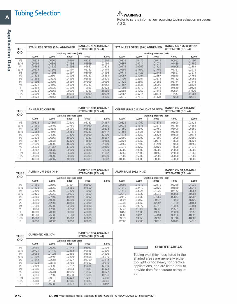
EATON Weatherhead Hose Assembly Master Catalog W-HYOV-MC002-E3 February 2011A-40
A
B
C
D
E
F
G
H
I
J
K
L
M
N
O
Ap
plicatio
n D
ata
.00238 .00476 .00714 .00952 .01190 .00357 .00714 .01071 .01429 .01786 .00476 .00952 .01429 .01905 .02381 .00595 .01190 .01786 .02381 .02976 .00714 .01429 .02143 .02857 .03571 .00957 .01904 .02857 .03810 .04762 .01190 .02381 .03571 .04762 .05952 .01429 .02857 .04286 .05714 .07143 .01667 .03333 .05000 .06666 .08333 .01904 .03810 .05714 .07619 .09524 .02381 .04762 .07143 .09524 .11905 .02857 .05714 .08371 .11429 .14286 .03810 .07619 .11428 .15238 .19048
.00333 .00666 .00999 .01333 .01666 .00499 .00999 .01498 .01999 .02499 .00666 .01332 .01998 .02667 .03333 .00833 .01665 .02497 .03333 .04165 .0099 .01998 .02997 .03999 .04998 .01332 .02664 .03996 .05333 .06664 .01665 .03333 .04995 .06666 .08330 .01998 .03996 .05994 .07999 .09996
.03333 .06666 .09999 .13333 .16666 .03996 .07992 .11988 .15999 .19992 .05328 .10656 .15984 .21333 .26666
.00833 .01667 .02500 .03333 .04167 .01250 .02499 .03750 .04999 .06250 .01667 .03333 .05000 .06666 .08333 .02083 .04167 .06250 .08333 .10417 .02499 .04999 .07500 .09999 .12499 .03333 .06667 .10000 .13333 .16667 .04167 .08333 .12500 .16666 .20883 .04999 .09999 .15000 .19999 .24999 .05833 .11667 .17500 .23333 .29166 .06667 .13333 .20000 .26666 .33333 .08333 .16667 .25000 .33333 .41667 .09999 .19999 .30000 .39999 .49999 .13333 .26667 .40000 .53333 .66667
.00625 .01250 .01875 .02500 .03125 .00938 .01875 .02812 .03750 .04688 .01250 .02500 .03750 .05000 .06250 .01562 .03125 .04688 .06250 .07812 .01875 .03750 .05625 .07500 .09375
.01250 .02500 .3750 .05000 .01875 .03750 .05650 .07500 .02500 .05000 .07500 .10000 .03125 .06250 .09375 .12500 .03750 .07500 .11250 .15000 .05000 .10000 .15000 .20000 .06250 .12500 .18750 .25000 .07500 .15000 .22500 .30000 .08750 .17500 .26250 .35000 .10000 .20000 .30000 .40000 .12500 .25000 .37500 .50000 .15000 .30000 .45000 .60000 .20000 .40000 .60000 .80000
.00806 .01613 .02419 .03226 .04032 .01210 .02419 .03629 .04839 .06048 .01613 .03226 .04839 .06452 .08065 .02016 .04032 .06048 .08065 .10081 .02419 .04839 .07258 .09677 .12097 .03227 .06452 .09677 .12903 .16129 .04032 .08065 .12097 .16129 .20161 .04839 .09677 .14516 .19355 .24194 .05645 .11290 .16935 .22581 .28226 .06452 .12903 .19355 .25806 .32258 .08065 .16129 .24194 .32258 .40323 .09677 .19355 .29032 .38710 .48387 .12903 .25806 .38710 .51613 .64516
working pressure (psi) 1,000 2,000 3,000 4,000 5,000
working pressure (psi) 1,000 2,000 3,000 4,000 5,000
.02331 .04662 .06996 .09333 .11662 .02664 .05328 .07992 .10666 .13328
1/83/161/45/163/81/25/83/47/81
1-1/41-1/2
2
TUBEO.D.
working pressure (psi) 1,000 2,000 3,000 4,000 5,000
working pressure (psi) 1,000 2,000 3,000 4,000 5,000
.02500 .05000 .07500 .10000 .12500 .03125 .06250 .09375 .12500 .15625 .03750 .07500 .11250 .15000 .18750 .04375 .08750 .13125 .17500 .21875 .05000 .10000 .15000 .20000 .25000 .06250 .12500 .18750 .25000 .31250 .07500 .15000 .22500 .30000 .37500 .10000 .20000 .30000 .40000 .50000
1/83/161/45/163/81/25/83/47/81
1-1/41-1/2
2
TUBEO.D.
working pressure (psi) 1,000 2,000 3,000 4,000 5,000
working pressure (psi) 1,000 2,000 3,000 4,000 5,000
1/83/161/45/163/81/25/83/47/81
1-1/41-1/2
2
TUBEO.D.
working pressure (psi) 1,000 2,000 3,000 4,000 5,000
.00481 .00962 .01442 .01923 .02404
.07692 .15385 .23077 .30769 .38462
1/83/161/45/163/81/25/83/47/81
1-1/41-1/2
2
TUBEO.D.
SHADED AREAS
Tubing wall thickness listed in the shaded areas are generally either too light or too heavy for practical applications, and are listed only to provide data for accurate computa-tion.
STAINLESS STEEL (304) ANNEALED BASED ON 75,000#/IN.2STRENGTH (F.S. –4)
STAINLESS STEEL (304) ANNEALED BASED ON 105,000#/IN.2STRENGTH (F.S. –4)
ANNEALED COPPER BASED ON 30,000#/IN.2STRENGTH (F.S. –4)
COPPER (UNS C12200 LIGHT DRAWN) BASED ON 40,000#/IN.2STRENGTH (F.S. –4)
ALUMINUM 3003 (H-14) BASED ON 20,000#/IN.2STRENGTH (F.S. –4)
ALUMINUM 5052 (H-32) BASED ON 31,000#/IN.2STRENGTH (F.S. –4)
CUPRO-NICKEL 30% BASED ON 52,000#/IN.2STRENGTH (F.S. –4)
.00721 .01442 .02163 .02885 .03606 .00962 .01923 .02885 .03846 .04808 .01202 .02404 .03606 .04808 .06010 .01442 .02885 .04327 .05769 .07212 .01923 .03846 .05769 .07692 .09615 .02404 .04808 .07212 .09615 .12019 .02885 .05769 .08654 .11538 .14423 .03365 .06731 .10096 .13462 .16827 .03846 .07692 .11538 .15385 .19231 .04808 .09615 .14423 .19231 .24038 .05769 .11538 .17308 .23077 .28846
WARNINGRefer to safety information regarding tubing selection on pages A-2-3.
Tubing Selection

EATON Weatherhead Hose Assembly Master Catalog W-HYOV-MC002-E3 February 2011 A-41
A
B
C
D
E
F
G
H
I
J
K
L
M
N
O
Ap
plica
tio
n D
ata
.028 .028 .028 .028 .028 .030 .030 .030 .030 .035 .030 .030 .030 .042 .049 .032 .032 .035 .049 .058 .032 .032 .042 .058 – .032 .042 .058 .072 – .035 .049 .072 .095 – .035 .058 .083 .109 – .049 .065 .095 – – .049 .072 .109 – – .049 .095 – – – .065 .109 – – – .072 – – – –
.028 .028 .028 .028 .035 .030 .030 .030 – – .030 .030 .042 .058 – .032 .032 .058 .065 – .032 .042 .058 – – .032 .058 .083 – – .035 .072 – – – .049 .083 – – – .049 .095 – – – .058 .109 – – – .072 – – – – .083 – – – – .109 – – – –
.028 .028 .028 .035 – .030 .030 – – – .030 .035 .058 – – .032 .049 .065 – – .032 .058 – – – .042 .072 – – – .049 .095 – – – .058 .109 – – – .065 – – – – .072 – – – – .095 – – – – .109 – – – – – – – – –
.028 .028 .028 .028 .028 .030 .030 .030 .030 .030 .030 .030 .030 .030 .042 .032 .032 .032 .042 .049 .032 .032 .035 .049 .058 .032 .032 .049 .065 .083 .035 .042 .058 .083 – .035 .049 .072 .095 – .049 .058 .083 – – .049 .065 .095 – – .049 .083 .120 – – .065 .095 – – – .065 – – – –
.028 .028 .028 .028 .030 .030 .030 .030 .035 – .030 .030 .035 .049 .058 .032 .032 .042 .058 – .032 .035 .058 .065 – .032 .049 .072 – – .035 .058 .095 – – .035 .072 .109 – – .049 .083 – – – .049 .095 – – – .058 .120 – – – .072 – – – – .095 – – – –
.028 .028 .028 .030 – .030 .030 .035 – – .030 .030 .049 – – .032 .042 .058 – – .032 .049 – – – .032 .065 – – – .042 .083 – – – .049 .095 – – – .058 .109 – – – .065 – – – – .083 – – – – .095 – – – – .134 – – – –
4:1 SAFETY FACTOR 8:1 SAFETY FACTOR6:1 SAFETY FACTOR
working pressure (psi) 1,000 2,000 3,000 4,000 5,000
working pressure (psi) 1,000 2,000 3,000 4,000 5,000
working pressure (psi) 1,000 2,000 3,000 4,000 5,000
1/83/161/45/163/81/25/83/47/81
1-1/41-1/2
2
TUBEO.D.
Both SAE 37° SINGLE FLARE FLARE-TWIN or ERMETO ® flareless recommended.
ERMETO® flareless only.
1010 STEEL TUBING WALL THICKNESS
4:1 SAFETY FACTOR 8:1 SAFETY FACTOR6:1 SAFETY FACTOR
working pressure (psi) 1,000 2,000 3,000 4,000 5,000
working pressure (psi) 1,000 2,000 3,000 4,000 5,000
working pressure (psi) 1,000 2,000 3,000 4,000 5,000
1/83/161/45/163/81/25/83/47/81
1-1/41-1/2
2
TUBEO.D.
1020 STEEL TUBING WALL THICKNESS
NOTE: Only Weatherhead Ermeto flareless fittings can be used with high pressure, heavy wall tubing which is impractical to flare.
WARNING
Refer to safety information regarding tubing selection on pages A-2-3. These tables provide data on required wall thickness for various sizes and pressures, and when to use flared or flareless fittings.
Although heavier wall tubing can be ordered for higher operating pressures, only standard size hydraulic tubing is listed in these tables. High temperature effects are not considered in these tables.
Tubing Selection
Note: Refer Only Weatherhead Ermeto flareless fitings can be used with high pressure, heavy wall tubing which is impractical to flare.

EATON Weatherhead Hose Assembly Master Catalog W-HYOV-MC002-E3 February 2011A-42
A
B
C
D
E
F
G
H
I
J
K
L
M
N
O
Ap
plicatio
n D
ata
.028 .028 .028 .028 .028 .030 .030 .030 .030 .030 .030 .030 .030 .030 .035 .032 .032 .032 .035 .042 .032 .032 .032 .042 .058 .032 .032 .042 .058 .072 .035 .035 .058 .072 .083 .035 .049 .065 .083 .109 .049 .049 .072 .095 – .049 .058 .083 .109 – .049 .072 .109 – – .065 .083 .120 – – .065 .109 – – –
.028 .028 .028 .028 .035 .030 .030 .030 .030 .035 .030 .030 .030 .042 .058 .032 .032 .035 .058 .065 .032 .042 .065 .083 – .032 .042 .065 .083 – .035 .058 .083 .095 – .035 .065 .095 – – .049 .072 .109 – – .049 .083 .120 – – .058 .109 – – – .065 .120 – – – .083 – – – –
.028 .028 .028 .028 .035 .030 .030 .030 .035 – .030 .030 .035 .058 .065 .032 .032 .049 .065 – .032 .042 .058 – – .032 .058 .083 – – .035 .065 – – – .049 .083 – – – .049 .095 – – – .058 .109 – – – .065 .134 – – – .083 – – – – .109 – – – –
.028 .028 .028 .028 .028 .030 .030 .030 .030 .030 .030 .030 .030 .030 .030 .032 .032 .032 .032 .032 .032 .032 .032 .032 .042 .032 .032 .032 .042 .049 .035 .035 .042 .049 .065 .035 .035 .049 .058 .072 .049 .049 .058 .072 .083 .049 .049 .058 .083 .095 .049 .049 .072 .095 .120 .065 .065 .095 – – .065 .083 .120 – –
.028 .028 .028 .028 .028 .030 .030 .030 .030 .030 .030 .030 .030 .030 .035 .032 .032 .032 .035 .049 .032 .032 .032 .042 .058 .032 .032 .042 .058 .072 .035 .035 .058 .072 .095 .035 .049 .065 .095 .109 .049 .058 .083 .109 – .049 .058 .095 – – .049 .072 .109 – – .065 .095 – – – .065 – – – –
.028 .028 .028 .028 .028 .030 .030 .030 .030 .035 .030 .030 .030 .042 .049 .032 .032 .035 .049 .058 .032 .032 .042 .058 – .032 .042 .058 .083 – .035 .049 .072 .095 – .035 .058 .095 – – .049 .065 .109 – – .049 .072 – – – .049 .095 – – – .065 – – – – .083 – – – –
4:1 SAFETY FACTOR 8:1 SAFETY FACTOR6:1 SAFETY FACTOR
working pressure (psi) 1,000 2,000 3,000 4,000 5,000
working pressure (psi) 1,000 2,000 3,000 4,000 5,000
working pressure (psi) 1,000 2,000 3,000 4,000 5,000
1/83/161/45/163/81/25/83/47/81
1-1/41-1/2
2
TUBEO.D.
Both SAE 37° SINGLE FLARE FLARE-TWIN or ERMETO® flareless recommended.
ERMETO® flareless only.
STAINLESS STEEL (304) ANNEALED TUBING WALL THICKNESS
4:1 SAFETY FACTOR 8:1 SAFETY FACTOR6:1 SAFETY FACTOR
working pressure (psi) 1,000 2,000 3,000 4,000 5,000
working pressure (psi) 1,000 2,000 3,000 4,000 5,000
working pressure (psi) 1,000 2,000 3,000 4,000 5,000
1/83/161/45/163/81/25/83/47/81
1-1/41-1/2
2
TUBEO.D.
STAINLESS STEEL (304) 1/8 HARD TUBING WALL THICKNESS
NOTE: Only Weatherhead Ermeto flareless fittings can be used with high pressure, heavy wall tubing which is impractical to flare.
WARNING
Refer to safety information regarding tubing selection on pages A-2-3. These tables provide data on required wall thickness for various sizes and pressures, and when to use flared or flareless fittings.
Although heavier wall tubing can be ordered for higher operating pressures, only standard size hydraulic tubing is listed in these tables. High temperature effects are not considered in these tables.
Note: Refer Only Weatherhead Ermeto flareless fitings can be used with high pressure, heavy wall tubing which is impractical to flare.
Tubing Selection

EatonHydraulics Group USA14615 Lone Oak RoadEden Prairie, MN 55344USATel: 952-937-9800Fax: 952-294-7722www.eaton.com/hydraulics
EatonHydraulics Group EuropeRoute de la Longeraie 71110 MorgesSwitzerlandTel: +41 (0) 21 811 4600Fax: +41 (0) 21 811 4601
EatonHydraulics Group Asia PacificEaton Building4th Floor, No. 3 Lane 280 Linhong Rd.Changning DistrictShanghai 200335ChinaTel: (+86 21) 5200 0099Fax: (+86 21) 5200 0400
© 2011 Eaton CorporationAll Rights ReservedPrinted in USADocument No. W-HYOV-MC002-E3Supersedes W-HYOV-MC002-E2February 2011