Embed Size (px)
DESCRIPTION
ecbc
Citation preview
Overview of ECBC envelope:
The building envelope refers to the exterior façade, and is comprised of opaque components and
fenestration systems. Opaque components include walls, roofs, slabs on grade (in touch with ground),
basement walls, and opaque doors. Fenestration systems include windows, skylights, ventilators, and
doors that are more than one-half glazed. The envelope protects the building‘s interiors and occupants
from the weather conditions and shields them from other external factors e.g: noise, pollution, etc
Envelope design strongly affects the visual and thermal comfort of the occupants, as well as energy
consumption in the building. The design of the building envelope is generally responsible of the
architect. The building designer is responsible for making sure that the building envelope is energy-
efficient and complies with the mandatory and prescriptive requirements of the code.
From an energy efficiency point of view, the envelope design must take into consideration both the
external and internal heat loads, as well as daylighting benefits. External loads include mainly solar
heat gains through windows, heat losses across the envelope surfaces, and unwanted air infiltration in
the building; internal loads include heat released by the electric lighting systems, equipment, and
people working in the building space. (Figure below)
Fig 1: External and Internal Heat Loads (source: ECBC, ECO III, US-AID)
Heat/Moisture
Losses
Walls Roof Window
Minimise conduction
losses
Use insulation with low
U-value
Use insulation with low
U-value
Use marerial with low U-
value
Minimise convection
losses & Moisture
penetration
Reduce air leakage & use
vapor barrier
Reduce air leakage & use
vapor barrier
Use prefabricated
window and seal the
joints between windows
and walls
Minimise Radiation
Losses
Use light coloured
coating with high
reflectance
Use light coloured
coating with high
reflectance
Use glazing with low
SHGC
Fig 2: ECBC Compliant Design Strategy for a Building (Source: Energy Conservation Building Code User Guide, BEE, ECO-
III)
ECBC Envelope
A well designed building envelope not only
helps in complying with the Energy
Conservation Building Envelope (ECBC) but
can also result in first cost savings by taking
advantage of daylighting and correct HVAC
sizing. The building envelope and its
components are key determinants of the amount
of heat gain and loss and wind that enters inside.
The envelope protects the building‘s interior and
occupants from the weather conditions and other
external elements. The design features of the
envelope strongly affect the visual and thermal
comfort of the occupants, as well as energy consumption in the building mentioned below are
explained further.
The commonly considered elements of ECBC envelope are:
1. Walls 2. window 3. Roof
The ECM2 is considered with ECBC envelope + Daylight Integration with optimum WWR Walls are a major part of the building. Envelope receives large amounts
of solar radiation. The heat storage capacity and heat conduction property
of walls are key to meeting desired thermal comfort conditions. The wall
thickness, materials and finishes can be chosen based on the heating and
cooling needs of the building. Appropriate thermal insulation and air
cavities in walls reduce heat transmission into building which is the
primary aim in a hot region.
The basic elements of the Wall system are:
1. Exterior cladding (natural or synthetic)
2. Drainage plane (s)
3. Air barrier system(s)
4. Vapour Retarder (s)
5. Insulating Element(s)
6. Structural elements
Thermal storage / thermal capacity: Thermal capacity is the measure of the amount of energy
required to raise the temperature of a layer of material, it
is a product of density multiplied by specific heat and
volume of the construction layer. The main effect of heat
Passive Design Features of Building Envelope and Fenestration (soure:www.energysavers.gov )
Wall
How Thermal Mass of a Building Works (source: www.eslarp.uiuc.edu )
storage within the building structure is to moderate fluctuation in the indoor temperature.
In a building system, we can understand thermal mass as the ability of a building material to store heat
energy to balance the fluctuations in the heat energy requirements or room temperature in the building
due to varying outside air temperature. The capacity to store heat depends upon the mass and
therefore on the density of the material as well as on its specific heat capacity. Thus, high density
materials such as concrete, bricks, stone are said to have high thermal mass owing to their high
capacity to store heat while lightweight materials such as wood, or plastics have low thermal mass.
The heat storing capacity of the building materials help achieve thermal comfort conditions by
providing a time delay. This thermal storage effect increases with increasing compactness, density and
specific heat capacity of materials.
Thermal performance of walls can be improved by following ways:
1. Increasing wall thickness
2. Providing air cavity between walls and hollow masonry blocks
3. Applying insulation on the external surface.
4. Applying light coloured distemper on the exposed side of the wall.
Conductance: Conductivity (K) is defined as the rate of heat flow through a unit area of unit thickness of the
material, by a unit temperature difference between the two sides. The unit is W/mK (Watt per metre -
degree Kelvin). The conductivity value varies from 0.03 W/mK for insulators to 400W/mK for
metals. Materials with lower conductivity are preferred, as they are better insulators and would reduce
the external heat gains from the envelope.
Walls-insulation: Thermal insulation is of great value when a building requires
mechanical heating or cooling insulation helps reduce the space-
conditioning loads. Location of insulation and its optimum thickness
are important. In hot climate, insulation is placed on the outer face
(facing exterior) of the wall so that thermal mass of the wall is likely
coupled with the external source and strongly coupled with the
interior (Bansal, Hauser, Minke 1994). Fig 4 Exterior wall insulation
Thermal properties of these materials are given below:
Material Conductivity
(W/m K)
Specific Heat
Capacity
(KJ/ Kg. K)
Density
(Kg/m3)
Brick 0.811 0.88 1820
Mud 0.750 0.88 1731
Stone 1.5 0.84 2200
Timber 0.072 1.68 480
Table 1: Thermal properties of different materials (source: ECBC user guide, BEE)

Air Cavities:
Air cavities within walls or an attic space in the roof-ceiling combination reduce the solar heat gain
factor, thereby reducing space-conditioning loads. The performance improves of the void is
ventilated. Heat is transmitted through the air cavity by convection and radiation. A cavity represents
a resistance, which is not proportional to its thickness. For a thickness >20mm, the resistance to heat
flow remains nearly constant. Ventilated air does not reduce radiative heat transfer from roof to
ceiling. The radiative component of heat transfer may be reduced by using low emissivity or high
reflective coating (E.g.: aluminum foil) on either surface facing the cavity. With aluminium foil
attached to the top of ceiling, the resistance for downward heat flow increases to about 0.4m2k/W,
compared to 0.21m2k/M in the absence of the foil (Bansal, Hauser, Minke, 1994).
Windows are very important component of the building envelope, in addition
to providing physical and visual connection to outside; it also allows heat and
light in and adds beauty to the building. Solar radiation coming in through
windows provides natural lighting, natural air and heat gain to the space inside,
thus significantly impacting the energy usage of the building. The main
purpose of a building and its windows is to provide thermal and visual comfort
to the occupants and if this can be achieved using less energy, so much the
better.
Proper location, sizing, and detailing of windows and shading form are
important part of the bio-climatic design as they help to keep the sun and wind
out of building or allow them when needed. The location of openings for
ventilation is determined by prevalent wind direction, openings at higher levels
naturally aid in venting out hot air. Size, Shape and orientation of openings
moderate air velocity and flow in the room, a small inlet and a large outlet increase the velocity and
distribution of air flow through the room. When possible, the house should be so positioned as the site
that it takes advantage of prevailing winds. The prevailing wind direction is from the south/south-east
during summer. The recommendation is IS: 3362-1977 code of practices for the design if windows for
lightly and ventilation. There should be sufficient air motion in hot-humid and warm-humid climates.
In such areas, fans are essential to provide comfortable air motion indoors, fenestrations having 15% -
20% of floor area are found adequate for both ventilation & day lighting in hot & dry, and hot &
humid regions. Natural light is also admitted into a building through glazed openings. Thus,
fenestrations design is primarily governed by requirements of heat gain and losses, ventilation and day
lighting. The important components of a window are the glazing systems and shading devices.
Window
Strip windows
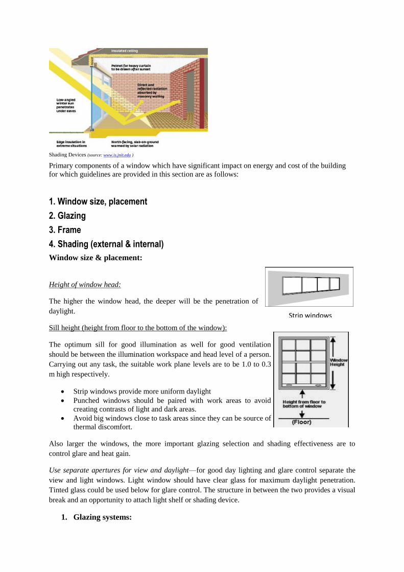
Shading Devices (source: www.is.jnit.edu )
Primary components of a window which have significant impact on energy and cost of the building
for which guidelines are provided in this section are as follows:
1. Window size, placement
2. Glazing
3. Frame
4. Shading (external & internal)
Window size & placement:
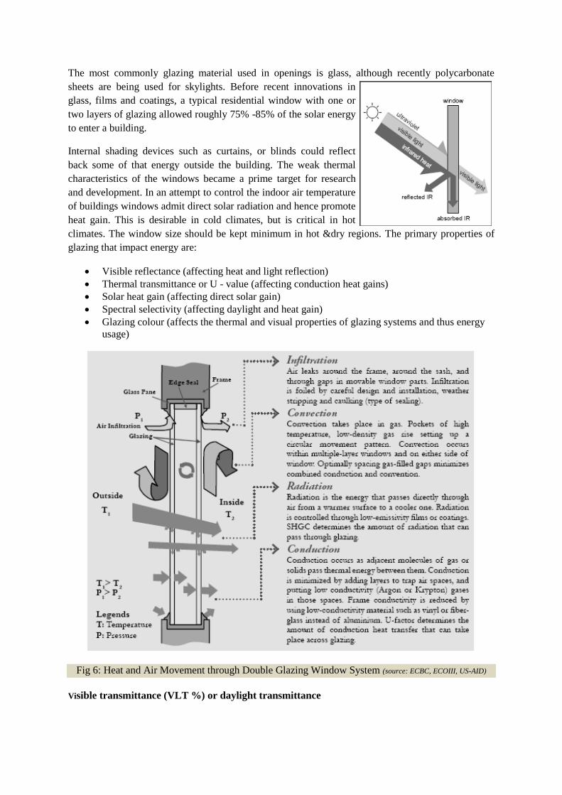
Height of window head:
The higher the window head, the deeper will be the penetration of
daylight.
Sill height (height from floor to the bottom of the window):
The optimum sill for good illumination as well for good ventilation
should be between the illumination workspace and head level of a person.
Carrying out any task, the suitable work plane levels are to be 1.0 to 0.3
m high respectively.
Strip windows provide more uniform daylight
Punched windows should be paired with work areas to avoid
creating contrasts of light and dark areas.
Avoid big windows close to task areas since they can be source of
thermal discomfort.
Also larger the windows, the more important glazing selection and shading effectiveness are to
control glare and heat gain.
Use separate apertures for view and daylight—for good day lighting and glare control separate the
view and light windows. Light window should have clear glass for maximum daylight penetration.
Tinted glass could be used below for glare control. The structure in between the two provides a visual
break and an opportunity to attach light shelf or shading device.
1. Glazing systems:
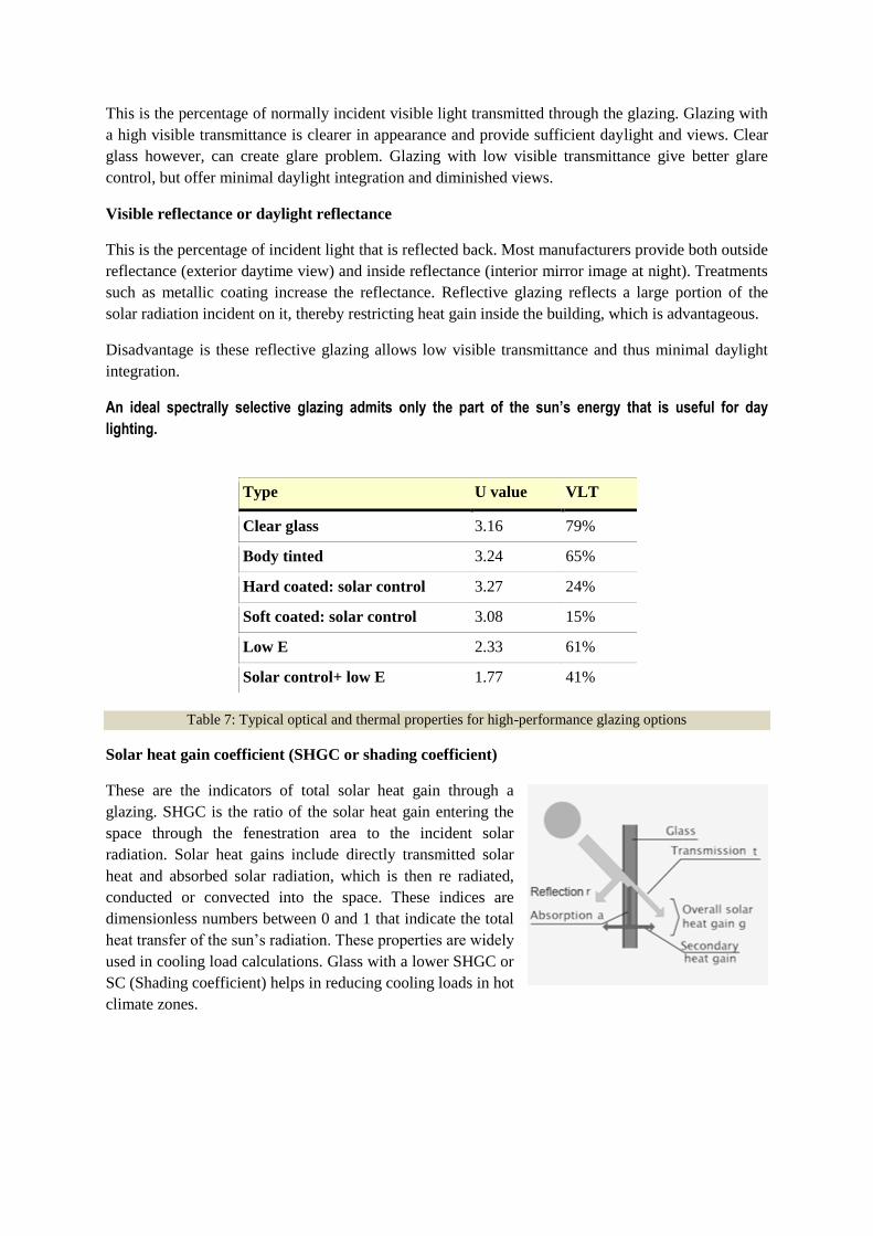
The most commonly glazing material used in openings is glass, although recently polycarbonate
sheets are being used for skylights. Before recent innovations in
glass, films and coatings, a typical residential window with one or
two layers of glazing allowed roughly 75% -85% of the solar energy
to enter a building.
Internal shading devices such as curtains, or blinds could reflect
back some of that energy outside the building. The weak thermal
characteristics of the windows became a prime target for research
and development. In an attempt to control the indoor air temperature
of buildings windows admit direct solar radiation and hence promote
heat gain. This is desirable in cold climates, but is critical in hot
climates. The window size should be kept minimum in hot &dry regions. The primary properties of
glazing that impact energy are:
Visible reflectance (affecting heat and light reflection)
Thermal transmittance or U - value (affecting conduction heat gains)
Solar heat gain (affecting direct solar gain)
Spectral selectivity (affecting daylight and heat gain)
Glazing colour (affects the thermal and visual properties of glazing systems and thus energy
usage)
Fig 6: Heat and Air Movement through Double Glazing Window System (source: ECBC, ECOIII, US-AID)
Visible transmittance (VLT %) or daylight transmittance
This is the percentage of normally incident visible light transmitted through the glazing. Glazing with
a high visible transmittance is clearer in appearance and provide sufficient daylight and views. Clear
glass however, can create glare problem. Glazing with low visible transmittance give better glare
control, but offer minimal daylight integration and diminished views.
Visible reflectance or daylight reflectance
This is the percentage of incident light that is reflected back. Most manufacturers provide both outside
reflectance (exterior daytime view) and inside reflectance (interior mirror image at night). Treatments
such as metallic coating increase the reflectance. Reflective glazing reflects a large portion of the
solar radiation incident on it, thereby restricting heat gain inside the building, which is advantageous.
Disadvantage is these reflective glazing allows low visible transmittance and thus minimal daylight
integration.
An ideal spectrally selective glazing admits only the part of the sun’s energy that is useful for day
lighting.
Type U value VLT
Clear glass 3.16 79%
Body tinted 3.24 65%
Hard coated: solar control 3.27 24%
Soft coated: solar control 3.08 15%
Low E 2.33 61%
Solar control+ low E 1.77 41%
Table 7: Typical optical and thermal properties for high-performance glazing options
Solar heat gain coefficient (SHGC or shading coefficient)
These are the indicators of total solar heat gain through a
glazing. SHGC is the ratio of the solar heat gain entering the
space through the fenestration area to the incident solar
radiation. Solar heat gains include directly transmitted solar
heat and absorbed solar radiation, which is then re radiated,
conducted or convected into the space. These indices are
dimensionless numbers between 0 and 1 that indicate the total
heat transfer of the sun‘s radiation. These properties are widely
used in cooling load calculations. Glass with a lower SHGC or
SC (Shading coefficient) helps in reducing cooling loads in hot
climate zones.
However, glass with a low SHGC also usually has low VLT. Hence use of glass with spectral
selectivity is recommended for day use air conditioned buildings to enhance day lighting and reduce
cooling loads. In air conditioned buildings, it is mandatory to achieve SHGC lower or equal to that
recommended by ECBC for various window wall ratios.
Adjusted SHGC
Adjusted SHGC is the cumulative solar heat gain coefficient of the window with both the glass and
shading devices (overhang, vertical fin or both).
Adjusted SHGC, which accounts for overhang and or side fins, is calculated by multiplying the SHGC
of the unshaded glass times a multiplication factor (M).
Adjusted SHGC = M * SHGC of glass
The multiplication factor (M) is identified for various projection factors (as per ECBC guidelines);
whenever the fenestration is provided with overhangs and/ or vertical fins, a separate ―M‖ factor shall
be determined for each orientation and unique shading condition. The multiplication factor is derived
from the projection factor and it is calculated based on the four ranges of PF (such as from 0.25 to
0.49, 0.50 to 0.74, 0.75 to 0.99 and 1.00 or more).
Glazing types and materials:
Until recently, single pane clear glass was the primary glazing material used in windows. The past
few decades have seen immense changes in glazing technology. Several types of advanced glazing
systems are available to help control heat loss or gain. The advanced glazing include double and triple
pane windows with coatings such as low - e (low emissivity)/ spectrally selective, heat absorbing
(tinted), or reflective, gas filled windows and windows based on combination of these options.
Substantial improvements in glazing performance are expected from new materials and techniques.
The creation of vacuum or partial vacuum in the cavity of a double glazed unit and the use of Aerogel
to fill the cavity can lower the U-value considerably. Air space between glass layers Thermal
resistance provided by the air cavity between glass layers increases with increase in cavity width upto
12mm. Convection currents, which form in wider cavities, lead to a drop in thermal resistance
Fig 7: Single glazing window Fig 8: Double glazing window (Source: www.green-planet-solar-energy.com )
Fig 8: Glazing materials (Source: www.gmpartitions.net )
Insulated glazing units
Insulating glazing units are hermetically sealed, multiple pane assembles consisting of two or more
glazing layers held and bonded at their perimeter by a space bar typically containing a desiccant
material. The glazing used in IGUs could be clear, tinted or coated or reflective as mentioned above.
The spacer serves to separate the panes of glass and to provide a surface for primary and secondary
sealant adhesion, since heat transfer at the edge of the IGU is greater than its centre. The choice of
material for spacer is critical to the IGUs performance. It is advisable to use SS, galvanized steel,
polymers or foamed silicon which have lower conductivities than aluminium. The hermetically sealed
space between glass panes is most often filled with air, argon and krypton being two other
alternatives.
Latest trends in glazing systems
a) Switchable glazing : Switchable glazing will enable the user to change the optical or thermal
properties of sealed glazed units. The most useful and potentially applicable switchable property is the
chromogenic phenomenon in which materials change their reflectivity and absorptivity. Examples of
chromogenic proceeese are: thermochromic, electrochromic and photochromic materials.
Thermochromic glazing changes optical properties in response to temperature changes. It consists of
mainly liquids or gels sandwitched between layers of glazing. Thermochromic windows are designed
to block solar gain. A drawback is that they reduce visible light transmission as well. Electrochromic
glazing changes optical properties when an electric current goes through the unit. A thin mettalic film
is deposited on the glass similar to low emissivity coatings. Another technique involves sandwiching a
liquid quartz film between two layers of glazing. Photochromic materials change their properties in
response to light. Photo gray sunglasses are best example. When photochromic materials change their
transmittance, the absorptivity is increased, thus causing glass to absorb more heat. On sunny, colds
days, they absorb solar heat and room source heat and then radiate some heat back to the
surroundings. On sunny, hot days, they do not reject as much solar heat as reflective glass.
b) Evacuated glazing : Evacuated, sealed insulated glazing is designed to achieve higher levels of
thermal performance by using a vacuum to inhibit any kind conductive or convective heat losses.
Flip windows for improved performance in summers and winters. The double pane absorptive glazing
system for hot climates has a useful feature for regions of composite climate, having both heating and
cooling seasons.
If the positions of the two glass panes are flipped over from their summertime positions during the
cold winter, the system converts to a solar radiant heater. In the cold day position, solar radiation
passes through the clear outer pane is absorbed by the inner pane, which heats up and then this heat is
transmitted to the inside, warming the building. The low - e coating on the inner pane now reduces the
radiation of heat from this hot inner pane to the cold outer one, trapping the heat inside. Flipping it
back over makes it a hot climate glazing system since the solar heat is now absorbed in the outer pane
of glass, which is insulated from the interior of the building.
Frame
The type and quality of window frame affects a window‘s air infiltration and heat gain / heat loss
characteristics. There are three kinds of framing material mostly used which are metal, wood and
polymers.
Wood has a good structural integrity and insulating values but low resistance to external
weather conditions.
Metal frames have poor thermal performance, but have excellent structural characteristics and
durability.
Aluminium is the most preferred metal for frames, but it is highly conductive and its thermal
performance can be improved with a thermal break (a non metal component which separates
the metal frame exposed to the outside from surfaces exposed to the inside.)
Vinyl window frames which are primarily made from polyvinyl chloride (PVC) offer many
advantages. Available in wide range of style and shapes PVC frames has high R– value
(Resistance value) and low maintenance.
U-value:
Table below shows how with the usage of different frame materials,
overall U– value varies. The below exercise was carried out using
WINDOW 5 as a tool, where glass and window size was not
changed, only on changing the frame difference in U– value was
observed. It should also be noted that the U-value of glass is lesser
than the overall u-value of the entire window, which is calculated by
the area weighted method, which includes the U– value of both
glass and frame.
Fig 9: Solar control interior shading
Daylighting and Window design:
Day lighting is utilization of light from the sun and sky to complement or replace electric light.
Appropriate fenestration and lighting controls can be used to modulate daylight admittance and to
reduce electric lighting, while meeting the occupants‘ visual comfort.
During day time when natural light, in outside, is available in abundance, window can be utilized as a
tool to harness natural light from sun and sky to light the space. Buildings, in which artificial lighting
is integrated with the day lighting, can reduce their energy bills significantly. Good day lighting in a
building depends upon the following factors –
External shading (Refer Technical Information on ECM1)
Internal shading
Solar control glass
Internal shading devices:
If properly adjusted, they can allow diffuse sunlight to penetrate
inside the space. However, they are not proffered over external
shading, as they do not keep solar heat out.
Good shading devices also reduces cooling loads. They
also modify the intensity and distribution of daylight
entering the space.
Solar control glazing:
They are very effective against heat flow across the window but can
reduce transmission of light inside the space.
Light shelves:
The function of light shelf is to protect the occupants from
direct sunlight in summer and allow sufficient light in winter.
The light shelf is placed above the eye level so that reflections
do not get into eyes of occupants. Uniform daylight is also
achieved as light is reflected deep into the room.
The light shelf should be sufficiently projected outside so as to protect the window.
The angle of the light shelf is also important as tilting helps in deeper light penetration but
also reflects light back.
The finishes should be reflective as matte surface reflects back about half light backwards
The top of the shelf should be matte white or diffusely specular, and not visible from any
point in the room.
Fig 10: solar control glazing
Fig 11: Modelling of Light shelves
Conventional Roof Insulation Practices
In India Roof Insulation with conventional materials like Foam
Concrete, Mud Faska, Brick Bat Coba has been practiced since ages.
However these products are quite heavy and add dead load to the roof
slab. Moreover the thermal conductivity value is very high which
results into higher thickness application without much benefit. These
products have the tendency to develop cracks and as a result water
absorption takes place. Moreover, the products are open cell and
porous type which results into water absorption. This application also calls for good workmanship.
What types of roofing products are available?
Products for low-slope roofs, found on commercial and industrial buildings fall into two categories:
single-ply materials and coatings. Single-ply materials are large sheets of pre-made roofing that are
mechanically fastened over the existing roof and sealed at the seams. Coatings are applied using
rollers, sprays, or brushes, over an existing clean, leak-free roof surface. Products for sloped roofs are
currently available in clay, or concrete tiles. These products stay cooler by the use of special pigments
that reflect the sun‘s infrared heat. In India, lime coats, white tiles grouted with white cement, special
paints, etc. are used as cool roofing materials.
Energy efficient roof insulations:
The roof requires significant solar radiation and plays an important role in heat gain/losses, day
lighting and ventilation. Depending on the climatic needs, proper roof treatment is essential. In a hot
region, the roof should have enough insulating properties to minimize heat gains. A few roof
protection methods are as follows:
A cover of decidous plants or creepers can be provided. Evaporation from roof surfaces will keep the
rooms cool. The entire roof surface can be covered with inverted earthen pots. It is also an insulated
cover of still air over the roof shading device. This can be mounted close to the roof in the day and
can be rolled to permit radiative cooling at night. The upper surfaces of the canvas should be painted
white to minimize the radiation absorbed by the canvas and consequent conductive heat gain through
it Effective roof insulation can be provided by using vermiculite concrete.
Heat gains through roofs can be reduced by adopting the following techniques.
(Source: www.construction-int.com)
Roof
Green roof concept
A roofing system through shading, insulation, evapo-
transpiration and thermal mass, thus reducing a
building‘s energy demands for space conditioning.
The green roof moderates the heat flow through the
roofing system and helps in reducing the temperature
fluctuations due to changing outside environment.
Green roof is a roof of a building that is partially or
completely covered with vegetation and soil that is
planted over waterproofing membrane. If widely
used green roofs can also reduce the problem of urban heat island which would further reduce the
energy consumption in urban areas.
Use of high reflective material on roof top.
Use light coloured roofs having an SRI (solar reflectance index) of
50% or more. The dark coloured, traditional roofing finishes have
SRI varying from 5 - 20%. A good example of high SRI is the use
of broken china mosaic and light coloured tiles as roof finish,
which reflects heat off the surface because of high solar
reflectivity and infrared emittance, which prevents heat gain and
thus help in reducing the cooling load from the building envelope.
If the roof is exposed to Solar heat it will input continuous heat inside the building which in turn will
add to the A.C. machinery load. This concept of protecting the roof is termed as Roof Insulation.
There are many different types of insulation materials to choose from when applying on a commercial
roof or reproofing an existing structure The function of roof insulation is to insulate the building
against heat in flow from outside during the day.
Use of higher albedo materials/cool roof:
Higher albedo materials can significantly reduce the heat island effect. Higher the albedo larger will
be the amount of solar radiation reflected back to the sky. Roofs provided with high reflective
coatings remains cooler than those with low reflectance surfaces and are known as cool roofs. Cool
roofs can reduce the building heat gain and can save the summertime air conditioning expenditures.
These paints are highly efficient, energy-saving, flexible coatings, made from water-based pure
acrylic resin system filled with vacuumed sodium borosilicate ceramic micro spheres of less than 100
microns in size. Each micro sphere acts as a sealed cell and entire mastic acts as a thermally efficient
blanket covering the entire structure. These coatings are non-toxic, friendly to the environment, and
form a monolithic (seamless) membrane that bridges hairline cracks. They are completely washable
and resist many harsh chemicals. Roof Coats have high reflectance and high remittance as well as a
very low conductivity value. They offer UV protection and low VOC's. They display excellent dirt
pick-up resistance and retain their flexibility after aging. These roof Coats reduce noise transmission
and have an effective use range from -40 Deg C (-40 Deg F) to 375 Deg C (700 Deg F) (Reference: www.thermoshieldindia.com )
Thermal insulation for roof:
Well insulated roof with the insulation placed on the external side is an effective measure to reduce
solar heat gains from the roof top. The insulated materials should be well protected by water proofing.
For air conditioned spaces, Energy Conservation Building Code (ECBC) recommends the thermal
performance for external roof for all the five climate zones in India.
source: www.divelodge.com
(source: www.smallflyingarts.com)
Over deck Insulation
In this system a thermal barrier or insulation is
provided over the RCC, so that the heat of the
sun is not allowed to reach the RCC slab of the
roof at all. In this way we can preserve the RCC
from getting heated up Once the RCC is heated
up there is no other way for the heat to escape
other than inside the building So ever though the
thermal barrier is provided under the RCC, as in
underdeck insulation, some heat passes through
it and heats up the ambience of the room. This decreases the comfort level of the room and if the
building is centrally AC, increases the AC load Hence we can safely conclude that overdeck
insulation has its own advantages over underdeck insulation. Overdeck Insulation material should
have adequate compression resistance, low water absorption, resistance to high ambient temp. and
low thermal conductivity. Overdeck insulation applications are carried out by either –
• Preformed insulation materials
• In-situ application
A) Preformed insulation material :
Preformed Insulation material are further classified as under :
• Expanded Polystyrene slabs
• Extruded Polystyrene slab
• Polyurethane / Polyisocyanurate slabs
• Perlite boads
(i) Expanded polystyrene (EPS, Thermocol)- is a light
weight cellular plastic foam material composed of carbon
and hydrogen atoms. It is derived from petroleum and
natural gas by products. Molded EPS does not involve the
use of CFCs. Polystyrene is highly economical EPS meets
most of the performance
(ii) Extruded Polystrene - Extruded Polystyrene is an
improvement of Expanded Polystyrene material. This
material is also comprise of beads / globules which are
compressed to form slabs and pipesections. Incase of
Extruded Polystyrene the beads are very closely linked to
each other so that the material become rigid and there is
no air gap between the beads. It is a close cells material
and a skin is formed on the top which stops water
absorption.
(iii) Polyisocyanurate / Polyurethane foam slab – These are
urethane foam insulation materials having low thermal
conductivity, low smoke emission & low water absorption.
The product confirms to IS:12436 & BS 5608.
( iv) Perlite – Perlite insulation is an organic rigid board
insulation. It is composed of expanded volcanic glass and
wood fibres bonded with asphaltic binders. This makes a
source: www.insulitte.com
(source: www.img.archiexpo.com)
(source: www.directindustry.com )
(source: www.alibaba.com )
rigid board light in weight, dimensionally stable and good in compressive strength. In
western countries at one time perlite was most common insulation material used for roof
insulation. Although still popular, its low ‗R‘ value, high ‗K‘ value and tendency to
absorb moisture have lessened its popularity.
The application procedure for overdeck insulation featuring preformed insulants are :
•Cleaning of the roof surface to be free of dirt and loose particles
•Providing a primer and adhesive coat
•Adhering of insulation with adhesive, taking care to seal all the joints between insulation also with a
sealant.
•Providing a protective plaster layer with reinforcement
•Providing an elastomeric membrane or felt type waterproofing treatment on top.
Insitu Technology
(i) Spray applied Polyurethane: Unlike preformed
materials, this is applied directly over the roof by
spraying. This eliminates separate fixing procedure. It is
formed spontaneously when Isocyanate and Polyol are
mixed in the presence of a blowing agent to create close
cell homogenous jointless insulation cover of the roof. It
is designed to combine highly efficient thermal insulation
with great ease of application It is ideal for a wide range
of insulation application particularly for roofs and walls of the building. By nature liquid
applied foam polyurethane adheres strongly to almost any surface regardless of form. The
seamless and monolithic nature of spray foam provides a full proof method of sealing
cracks and rendering any surface moisture resistance and drought proof. The excellent
adhesion of the sprayed material makes mechanical fastening redundant. The
comparatively low density of material adds little weight to overall loading. Besides
external use, sprayed foam can be applied internally as well. (The foam can also be
sprayed on the under side of roofs and suspended floors and on inner surface of walls).
Insulation
The first set of mandatory requirements addresses the proper installation and protection of insulation
materials. It is recommended that insulation materials be installed according to the manufacturer‘s
recommendations and in a manner that will achieve the rated insulation R-value. Compressing the
insulation reduces the effective R-value and the thermal performance of the construction assembly.
Substantial Contact
It is recommended that insulation be installed in a permanent manner and in substantial contact with
the inside surface of the construction assembly. If the insulation does not entirely fill the cavity, the
air gap should be on the outside surface. Maintaining substantial contact is particularly important (and
problematic) for batt insulation installed between floor joists. Without proper support, gravity will
cause the insulation to fall away from the floor surface, leaving an air gap above the insulation. Air
currents will ultimately find their way to the gap, and when they do, the effectiveness of the insulation
will be substantially reduced.
Insulation above Suspended Ceilings
It is not good practice to install insulation directly over suspended ceilings with removable ceiling
panels.
This is because the insulation‘s continuity is likely to be disturbed by maintenance workers. Also,
suspended ceilings may not meet the ECBC‘s infiltration requirements unless they are properly
sealed. Compliance with this requirement could have a significant impact in some parts of the
country, as it is common practice to install insulation over suspended ceilings. Many building codes
will consider the space above the ceiling to be an attic and require that it be ventilated to the exterior.
(source: www.archiexpo.com)
If vented to the exterior, air in the attic could be quite cold (or hot) and the impact of the leaky
suspended ceiling would be made worse.
Insulation Protection
It is strongly recommended that insulation be protected from sunlight, moisture, landscaping
equipment, wind, and other physical damage. Rigid insulation used at the slab perimeter of the
building should be covered to prevent damage from gardening or landscaping equipment. Rigid
insulation used on the exterior of walls and roofs should be protected by a permanent waterproof
membrane or exterior finish. In general, a prudent designer should pay attention to moisture migration
in all building construction. Vapor retarders prevent moisture from condensing within walls, roofs, or
floors but care should be taken to install them on the correct side (warmer or cooler side) of the walls
and roofs to prevent water damage. Water condensation can damage the building structure and can
seriously degrade the performance of building insulation and create many other problems such as
mold and mildew. The designer should evaluate the thermal and moisture conditions that might
contribute to condensation and make sure that vapor retarders are correctly installed to prevent
condensation. In addition to correctly installing a vapor retarder, it is important to provide adequate
ventilation of spaces where moisture can build up.
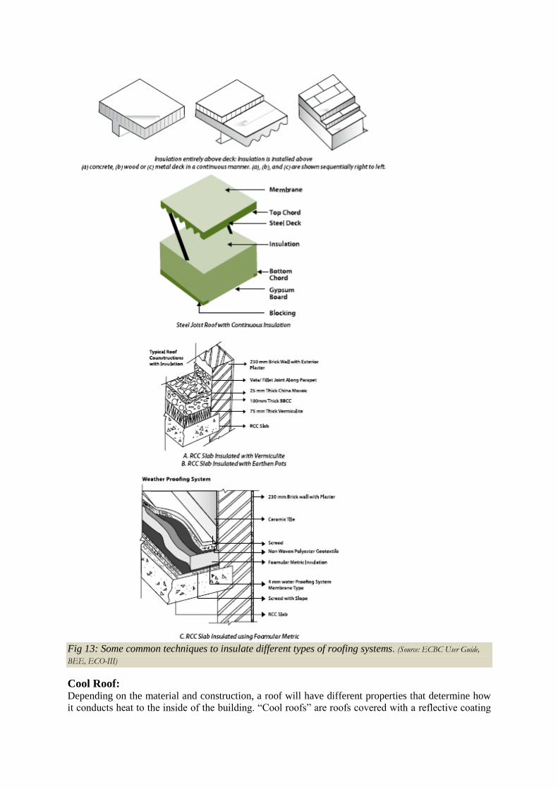
Fig 13: Some common techniques to insulate different types of roofing systems. (Source: ECBC User Guide,
BEE, ECO-III)
Cool Roof: Depending on the material and construction, a roof will have different properties that determine how
it conducts heat to the inside of the building. ―Cool roofs‖ are roofs covered with a reflective coating
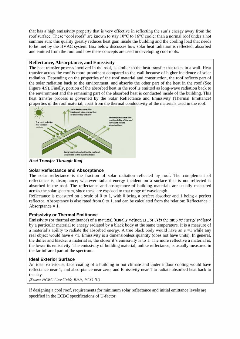
that has a high emissivity property that is very effective in reflecting the sun‘s energy away from the
roof surface. These ―cool roofs‖ are known to stay 10°C to 16°C cooler than a normal roof under a hot
summer sun; this quality greatly reduces heat gain inside the building and the cooling load that needs
to be met by the HVAC system. Box below discusses how solar heat radiation is reflected, absorbed
and emitted from the roof and how these concepts are used in developing cool roofs.
Reflectance, Absorptance, and Emissivity
The heat transfer process involved in the roof, is similar to the heat transfer that takes in a wall. Heat
transfer across the roof is more prominent compared to the wall because of higher incidence of solar
radiation. Depending on the properties of the roof material and construction, the roof reflects part of
the solar radiation back to the environment, and absorbs the other part of the heat in the roof (See
Figure 4.9). Finally, portion of the absorbed heat in the roof is emitted as long-wave radiation back to
the environment and the remaining part of the absorbed heat is conducted inside of the building. This
heat transfer process is governed by the Solar Reflectance and Emissivity (Thermal Emittance)
properties of the roof material, apart from the thermal conductivity of the materials used in the roof.
Heat Transfer Through Roof
Solar Reflectance and Absorptance The solar reflectance is the fraction of solar radiation reflected by roof. The complement of
reflectance is absorptance; whatever radiant energy incident on a surface that is not reflected is
absorbed in the roof. The reflectance and absorptance of building materials are usually measured
across the solar spectrum, since these are exposed to that range of wavelength.
Reflectance is measured on a scale of 0 to 1, with 0 being a perfect absorber and 1 being a perfect
reflector. Absorptance is also rated from 0 to 1, and can be calculated from the relation: Reflectance +
Absorptance = 1.
Emissivity or Thermal Emittance Emissivity (or thermal emittance) of a m
by a particular material to energy radiated by a black body at the same temperature. It is a measure of
a material‘s ability to radiate the absorbed energy. A true black body would have an e =1 while any
real object would have e <1. Emissivity is a dimensionless quantity (does not have units). In general,
the duller and blacker a material is, the closer it‘s emissivity is to 1. The more reflective a material is,
the lower its emissivity. The emissivity of building material, unlike reflectance, is usually measured in
the far infrared part of the spectrum.
Ideal Exterior Surface An ideal exterior surface coating of a building in hot climate and under indoor cooling would have
reflectance near 1, and absorptance near zero, and Emissivity near 1 to radiate absorbed heat back to
the sky. (Source: ECBC User Guide, BEE, ECO-III)
If designing a cool roof, requirements for minimum solar reflectance and initial emittance levels are
specified in the ECBC specifications of U-factor:
Roofs with slopes less than 20° shall have an initial solar reflectance of no less than 0.70 and an initial
emittance no less than 0.75. Solar reflectance shall be determined in accordance with ASTM E903-96
and emittance shall be determined in accordance with ASTM E408-71 (RA 1996).
In hot climates, cool roofs (or high emissivity or thermal emittance roof surfaces) are an effective way
to reduce solar gains and cut building owners‘ energy costs. Because cool roofs gain less heat than
normal roofs, they reduce the need for air conditioning and make buildings more comfortable to the
people inside. The light color reflects sunlight and heat away from the building, and the high
emissivity or thermal emittance allows heat to escape to the atmosphere when the surface becomes
heated. Although some surfaces, such as galvanized metal, have a high reflectance, they have a low
emittance.
These surfaces reflect heat, but heat that is absorbed cannot escape. Other surfaces, such as dark paint,
have a high emittance but a low reflectance. These surfaces allow heat to escape, but do a poor job of
reflecting heat that strikes the surface.
Most cool roof materials for low-sloped roofs are white or another light color. For steep-sloped roofs
that are often visible from the ground, roofing material manufacturers have developed popular roof
colors other than white that will still reflect solar radiation or emit the sun‘s energy away from the
building.
Cool roofs have other benefits in addition to reducing operating absorbed heat costs. For building
owners, they can cut maintenance costs and increase the life expectancy of the roof. For society in
general, cool roofs can even help to reduce the urban heat island effect and slow down global
warming that makes our cities hotter and produces unhealthy air.
MANUFACTURERS LIST
Manufacturers list of materials that comply with ECBC for wall, window and roof are mentioned below.
Manufacturers list of Wall Insulations:
Some of the manufacturers of solar lights and equipments are as mentioned below. The list mentioned
below is not extensive and has to be checked in the market for more updates and more information.
BEARDSELL LIMITED
U.P TWIGA FIBERGLASS LIMITED
TROCELLEN
NANOGEL
CANI MERCHANDISING PVT.LTD
SANROK
DOW CHEMICAL INTERNATIONAL PVT.LTD
WACKER POLYMER SYSTEMS GMBH & CO. KG
LLOYD INSULATIONS (INDIA) LTD
FIBREX INDUSTRIES
SUNSULATE INSULATION PVT. LTD
SUZERAIN INSULATORS
SUD AND WAREN PVT LTD
PERFECT PAPERS
MAG HARD INSULATORS
AGNI FIBER BOARDS PVT. LTD
S.S INSULATION
ROCKWOOL (INDIA) LIMITE
KONIFER INDIA
UMANG BOARDS PRIVATE LIMITED
SIGMA SEALING & INSULATION PRIVATE LIMITED
List of Manufacturers:
Some of the important manufacturers list of glass and glass products is mentioned below.The list of
manufacturers mentioned below is not comprehensive and needs to be checked with the updated list in
the market.
SAINT-GOBAIN GLASS INDUSTRIES
GARWARE POLYSTER LIMITED
MEHLER TECHNOLOGIES GMBH
SEJAL GLASS
ASAHI INDIA GLASS LTD
DAFFODIL GLASS
GLASS CONSORTIUM
UNIVERSAL GLASS TRADERS
INDO ALUSYS INDUSTRIES LIMITED
SUPERIOR GLASS
GLASS AND GLAZING SYSTEMS (P) LTD.
HINDUSTAN GLASS WORKS LTD
Manufacturers list of Roof Insulations:
Some of the manufacturers of solar lights and equipments are as mentioned below. The list mentioned
below is not extensive and has to be checked in the market for more updates and more information.
INDUSTRIAL FOAMS (P) LTD
FALCONN FIBRE
DUGAR INSULATIONS INDIA (P) LTD
AMOL DICALITE LIMITED
MACBERTAN (P) LTD
LLOYD INSULATIONS INDIA (P) LTD
EXCEL COATINGS
SHALAK INTERNATIONAL
OWENS CORNING (INDIA) LTD
OZTEN LTD
SHATEX LUBRZOLE
ENERCON
Day lighting has a major effect on the appearance of space and can have considerable implications on
energy efficiency, if used properly. Its variability is subtly pleasing to the occupant in contrast to the
relatively monotonous environment produced by artificial light. It helps to create optimum working
conditions by bringing out the natural contrast and colour of objects. The presence of natural light can
bring a sense of well being and awareness of the wider environment. Day lighting is important
particularly in commercial and other non-domestic buildings that function during the day. Integration
of day lighting with artificial light brings about considerable savings in energy consumption. A good
day lighting system, has number of elements most of which must be incorporated into the building
design at an early stage. This can be achieved by considering the following relation to the incidence of
day light on the building.
• Orientation, space organization and geometry of the space to be lit
• Location, form & dimension of the fenestrations through which day light will enter
• Location & surface properties of internal partitions that affect the day light distribution by reflection
• Location, form and dimensions of shading devices that provides protection from excessive light and
glare
• Light and thermal characteristics of the glazing materials
Tangible benefits of Natural day lighting integration:
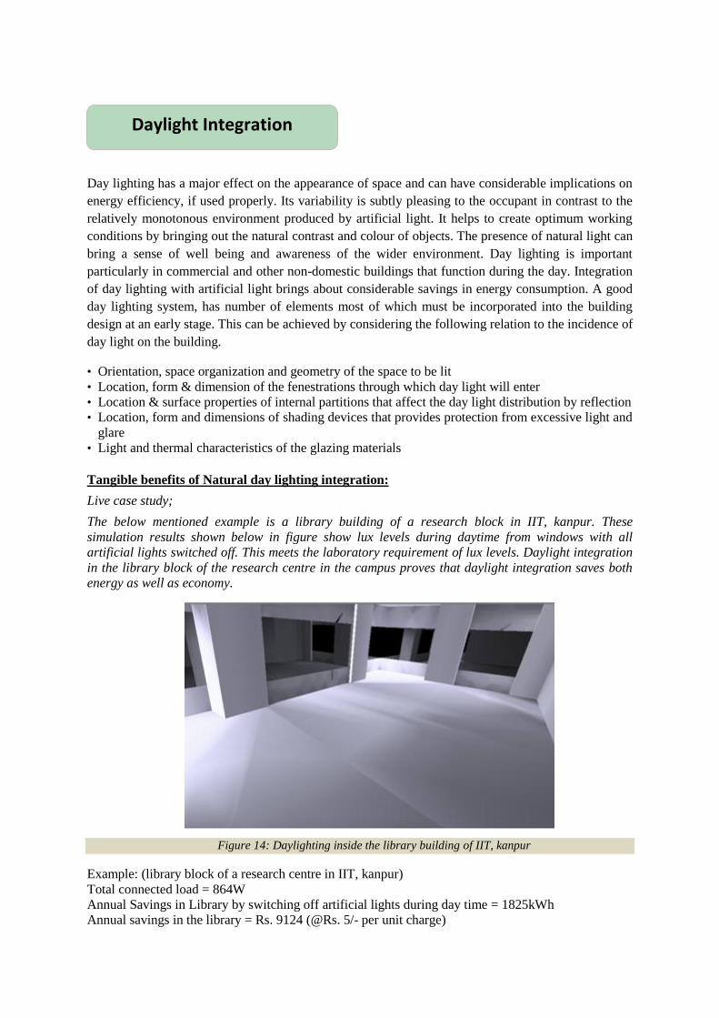
Live case study;
The below mentioned example is a library building of a research block in IIT, kanpur. These
simulation results shown below in figure show lux levels during daytime from windows with all
artificial lights switched off. This meets the laboratory requirement of lux levels. Daylight integration
in the library block of the research centre in the campus proves that daylight integration saves both
energy as well as economy.
Figure 14: Daylighting inside the library building of IIT, kanpur
Example: (library block of a research centre in IIT, kanpur)
Total connected load = 864W
Annual Savings in Library by switching off artificial lights during day time = 1825kWh
Annual savings in the library = Rs. 9124 (@Rs. 5/- per unit charge)
Daylight Integration
Relation between WWR and VLT to achieve recommended daylight levels:
Table 10: Recommended daylight factors for interiors as per Bureau of Indian Standards SP:41(S&T). DF
1%=80 lux. Design sky illuminance 8000lux.
Sl. No. Location Daylight Factor %
1 Dwellings Kitchen 2.5
Living Room 0.625
Study room 1.9
Circulation 0.313
2 Schools
Class room desk top, black board 1.9—-3.8
Laboratory 2.5—3.8
3 Offices/commercial spaces
General 1.9
Drawing, typing 3.75
Enquiry 0.625—1.9
4 Hospitals
General wards 1.25
Pathological laboratory 2.5-3.75
5 Libraries
Stack room 0.9—1.9
Reading room 1.9-3.75
Counter area 2.5—-3.75
Catalogue room 1.9—2.5
As per BIS, the recommended daylight level for an office space, in the centre of the room should be
150lux. To achieve, the above BIS recommended daylight levels in a commercial building (table 1),
window optimisation analysis had been carried out by using simulations for various WWR ranging
from 10% to 100% and VLT values of glass ranging from 10% to 90% in the project ― High
performance commercial buildings in India‖. Lighting levels were calculated to identify what % of
WWR and VLT in combination achieves the daylight levels recommended by BIS and to find out the
optimum WWR. From the analysis the following Table is obtained which shows the relation between
WWR and VLT to achieve the BIS recommended daylight levels. The following table also helps in
selecting the optimum WWR with corresponding VLT of glass to meet the recommended daylight
levels in a working space.
Daylight Factors at the Centre of the day lit zone
Visual Light
Transmittance
of Glass (%)
DF for
WWR
10%
DF for
WWR
20%
DF for
WWR
30%
DF for
WWR
40%
DF for
WWR
50%
DF for
WWR
60%
DF for
WWR
70%
DF for
WWR
80%
DF for
WWR
90%
DF
for
WWR
100%
10 0.3 0.5 0.6 0.7 0.8 0.8 0.9 0.9 0.9 0.9
20 0.6 1.0 1.2 1.4 1.5 1.7 1.7 1.8 1.8 1.9
30 1.0 1.6 1.8 2.1 2.3 2.5 2.6 2.7 2.7 2.8
40 1.2 2.1 2.4 2.8 3.1 3.3 3.4 3.6 3.6 3.7
50 1.5 2.6 3.1 3.5 3.8 4.1 4.3 4.5 4.5 4.6
60 1.9 3.1 3.7 4.2 4.5 5.0 5.2 5.4 5.4 5.6
Table 11: Relation between WWR and VLT to achieve recommended daylight levels
The highlighted are the cases for each WWR for which the minimum corresponding VLT of glass is
required to meet the recommended day light factor in an office space. It was observed that minimum
10% WWR & 60% VLT of the glass is required to achieve the recommended illumination and
daylight factor at the centre of the day lit zone in an office building. Similarly 40% VLT is
required for WWR 20% and 30% to meet the required day lit levels. For WWR ranging from
40-90% minimum VLT required is 30% to achieve the day lit levels.
Surface Reflectance: For daylight integration, the desirable internal and external finish of the
building should be light in colour, as light colored surfaces will reflect more daylight than dark
surfaces. Desirable reflectance inside a room and common finishes to achieve them are provided in
table below.
Surface Desirable reflectance Typical finish to achieve reflectance
Ceiling 0.7—0.8 White colour
Wall 0.5—0.6 Cream, light green
Table top 0.35-0.5 Brick colour
Floor 0.15-0.3 Medium Grey
Table 12: Desirable reflectance levels in a room
Innovative Day lighting systems:
Day lighting systems help in better daylight integration in the buildings. There are various
day lighting systems. Some of them are as explained below:
Light pipes:
Light tubes or light pipes are used for transporting or distributing
natural or artificial light. In their application of day lighting, they are
also called as sun pipes, solar pipes, solar light pipes, or day light pipes.
Generally, it may refer to “a tube or pipe for transport of light to
another location, minimizing the loss of light.”
They make it possible to transport daylight through thick roof structures
and attics. They are easier to install in retrofit applications than
skylights. For practical reasons, light pipes are limited to smaller light
collection areas.
If the building has an attic, installing skylights in the roof requires building a reflective enclosure to
pass the light through the attic. Unless the attic is empty, this may be difficult. Light pipes are easier
Window Wall ratio Minimum VLT
0.10 0.60
0.20 – 0.30 0.40
0.40 – 0.70 0.30
Figure 15: Typical light pipe
(Source: www.greenedmonton.ca)
to pass through attics. In effect, a light pipe is a small skylight with an integral reflective enclosure.
The light pipe has to be made of a solid transparent material, such as glass or plastic.
The light pipe can be long, and it can have any number of bends.
To make economical, all the light has to be squeezed in to a light piece of small diameter.
A small conduit is desirable to minimise heat loss and to make the light pipe easy to install.
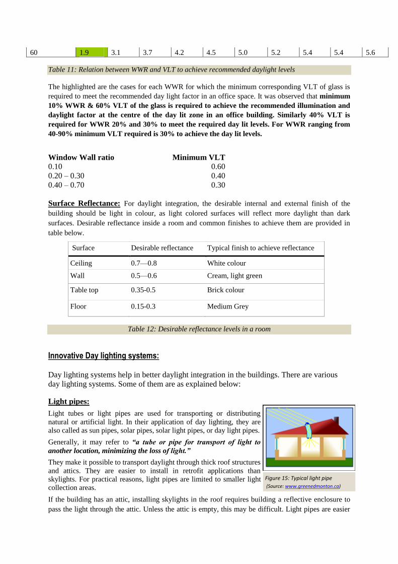
There are 2 types of light pipes:
1. Simple light pipes: (rigid wall light pipe & flexible wall light pipe as shown in figures below)
2. Sun trackers
1. Simple light pipes:
The pipe may be rigid or flexible. Flexible light pipes are easier to install but they suffer more light
loss from increased reflection and scatter inside the pipe
2. Sun trackers:
A movable mirror or refracting system can be used to align the incoming sunlight with the axis of the
pipe, minimizing reflecting losses which is called as ―sun tracker‖
Figure 16: Rigid & flexible wall light pipe (source: www.reliant.com ) Figure 17: sun tracker (source:www.reuk.co.uk )
For better daylight integration ECBC also recommends Day lighting controls.
Day lighting control as per ECBC recommendations:
Luminaries in day lighted areas greater than 25m² (250ft²) shall be equipped with either a manual or
automatic control device that;
Is capable of reducing the light out put of the luminaries in the day lighted areas by at least
50% and;
Controls only the luminaries located entirely within the day lighted areas
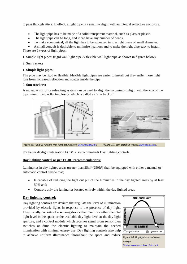
Day lighting control:
Day lighting controls are devices that regulate the level of illumination
provided by electric lights in response to the presence of day light.
They usually consists of a sensing device that monitors either the total
light level in the space or the available day light level at the day light
aperture, and a control module which receives signal from sensor then
switches or dims the electric lighting to maintain the needed
illumination with minimal energy use. Day lighting controls also help
to achieve uniform illuminance throughout the space and reduce Figure 18: Daylight control saves
energy (Source:www.greenboxretail.com)
conditions of over lighting.
For spaces that receive significant day light, Daylight Harvesting Controls can be used to keep
lights off, or to dim lights. The simplest systems simply turn off the lighting circuit when a pre-
determined level of illumination is achieved through daylight. Because these systems require a high
level of daylight throughout the space, systems that turn off only a portion of the lights are often more
effective. For example, two lamps in a four-lamp fixture might be turned off, or the row of fixtures
nearest the windows might be turned off in response to daylight. Daylight dimming systems are the
most elegant, but they require special stepped or continuous dimming ballasts.
Control techniques:
On/off day light switching is the most economical approach,
but may create light level changes in work areas. It is most
successful in circulation areas and non critical work areas. (Ex;
multilevel switching schemes)
Dimming systems have higher costs, but will be more
acceptable in high work areas. (Ex: Dimming ballasts)
Window Wall Ratio (WWR)
Window Wall Ratio is the ratio of vertical fenestration area to gross
exterior wall area. Gross exterior wall area is measured horizontally from
the exterior surface; it is measured vertically from the top of the floor to
the bottom of the roof.
Example – The wall shown in the figure has width ‗W‘ and height
‗H‘. The window height is ‗a‘ and width is ‗b‘ as shown in figure.
The WWR for the given facade will be = (a x b)/(H x W)
Figure20: Explanation of WWR
Optimisation of Window Wall Ratio (WWR) and daylight integration
Analysis using simulation engines was carried out in this project ―High Performance Commercial
buildings in India‖ to observe the impact of various WWR on the cooling energy demand. As
expected the cooling energy demand increases with increase in window wall ratio. Therefore ECBC
has made glass selection more stringent with higher WWR. The figure below shows a reduction in
cooling energy consumption for higher WWR, if a higher performance glass with higher WWR is
used.
OPTIMUM WWR
Figure 19: Daylight control (Source:www.lightingcontrols.com)
E nerg y us e in B as e c as e & E C B C env elope c as e
1,150,000
1,200,000
1,250,000
1,300,000
1,350,000
1,400,000
10 20 30 40 50 60
WWR
En
erg
y u
se
(k
Wh
)
B as e cas e E C B C E nvelope
E nerg y us e in B as e c as e & E C B C env elope c as e
1,150,000
1,200,000
1,250,000
1,300,000
1,350,000
1,400,000
10 20 30 40 50 60
WWR
En
erg
y u
se
(k
Wh
)
B as e c as e E C B C E nvelope
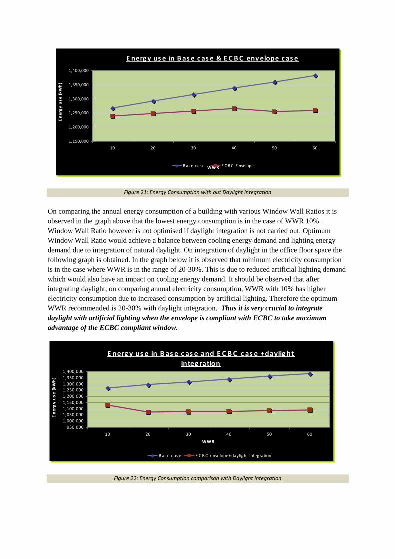
Figure 21: Energy Consumption with out Daylight Integration
On comparing the annual energy consumption of a building with various Window Wall Ratios it is
observed in the graph above that the lowest energy consumption is in the case of WWR 10%.
Window Wall Ratio however is not optimised if daylight integration is not carried out. Optimum
Window Wall Ratio would achieve a balance between cooling energy demand and lighting energy
demand due to integration of natural daylight. On integration of daylight in the office floor space the
following graph is obtained. In the graph below it is observed that minimum electricity consumption
is in the case where WWR is in the range of 20-30%. This is due to reduced artificial lighting demand
which would also have an impact on cooling energy demand. It should be observed that after
integrating daylight, on comparing annual electricity consumption, WWR with 10% has higher
electricity consumption due to increased consumption by artificial lighting. Therefore the optimum
WWR recommended is 20-30% with daylight integration. Thus it is very crucial to integrate
daylight with artificial lighting when the envelope is compliant with ECBC to take maximum
advantage of the ECBC compliant window.
E nerg y us e in B as e c as e and E C B C c as e +daylig ht
integ ration
950,000
1,000,000
1,050,0001,100,000
1,150,000
1,200,000
1,250,0001,300,000
1,350,000
1,400,000
10 20 30 40 50 60
WWR
En
erg
y u
se
(k
Wh
)
B as e cas e E C B C envelope+ daylight integration
E nerg y us e in B as e c as e and E C B C c as e +daylig ht
integ ration
950,000
1,000,000
1,050,0001,100,000
1,150,000
1,200,000
1,250,0001,300,000
1,350,000
1,400,000
10 20 30 40 50 60
WWR
En
erg
y u
se
(k
Wh
)
B as e cas e E C B C envelope+ daylight integration
Figure 22: Energy Consumption comparison with Daylight Integration