Embed Size (px)
Citation preview

6th European Conference on Computational Mechanics (ECCM 6)
7th European Conference on Computational Fluid Dynamics (ECFD 7)
11 – 15 June 2018, Glasgow, UK
COMPARISON OF SINGLE-SOLVER FSI TECHNIQUES FOR THE FE-
PREDICTION OF A BLOW-OFF PRESSURE FOR AN ELASTOMERIC SEAL
(ECCM –ECFD 2018 CONFERENCE)
NIALL MORRISON¹, YEVGEN GORASH² AND ROBERT HAMILTON³
123Department of Mechanical and Aerospace Engineering, University of Strathclyde
Glasgow G1 1XJ, UK
Key words: Finite Element Analysis, Fluid-Structure Interaction, Seal, Leakage
Summary: Assessment of leakage performance is a fundamental aspect in the design of
elastomeric fluid seals. The key characteristic of the leakage performance is the blow-off
pressure, which when it is reach, the leakage rate through the seal is no longer acceptable and
the seal no longer performs its function. Prediction of the blow-off pressure under different
operating conditions such as the amount of preload, pressure build-up rate, etc., would
facilitate improvement in the seal design methodology and would allow subsequent efficient
optimisation of a seal design. For an accurate prediction of the blow-off pressure, any
computational methodology should ideally include Fluid-Structure Interaction (FSI), since the
geometrical disposition of the seal, its deformation and its contact conditions with respect to
the main structure are adversely affected by the fluid pressure. Two FSI single-solver
techniques, available in the commercial FE-code Abaqus, are investigated in this study with
application to the simulation of leakage. The first technique is Pressure Penetration
Interaction, available for general structural analysis using a static implicit solver, which
propagates the applied fluid pressure into contact openings. The second, more advanced FSI
technique, is the Coupled Eulerian-Lagrangian (CEL) approach which is available for coupled
fluid-structural analysis in a dynamic explicit solver. The CEL approach is the most versatile
and can be applied to a wide range of FSI problems, e.g. simulation of a seal blow-off and fluid
leakage through the resulting contact gap [1]. When trying to develop the art and science
involved in the simulation of leakage phenomenon, a robust FSI technique has the potential to
be a critically important design tool which could be applied to a wide range of more complex
sealing geometries. This paper addresses a typical hollow rubber seal and investigates how the
amount of initial compression and initial stretching affect the leak tightness of the seal using
two different FSI techniques. The complexity of problem setup, the efficiency of the solver and
the robustness of obtained solution will be compared and discussed.

Niall Morrison, Yevgen Gorash and Robert Hamilton
2
1 INTRODUCTION
1.1 Problem introduction
Accurate simulation of fluid structure interaction is a long running problem in the world of
fluid sealing. This report will attempt to address the difficulties associated with this type of
problem by employing the coupled Eulerian-Lagrangian (CEL) approach to facilitate
computationally efficient, and accurate, prediction of the blow off pressure for a seal of typical
geometry [2] and material properties.
The simulation work was completed using ABAQUS 2018, the CEL approach provided in
this package allows for simultaneous computation of the fluid, and structure interaction effects,
within one environment. This technique is a more advanced version of the arbitrary Eulerian-
Lagrangian (AEL) [3] approach which utilises adaptive re-meshing and transfers results taken
at the solid boundary of a fluid problem, to the solid boundary of a solid problem, for each
individual time step. This transferring of results leads to interpolation between the time steps
which can give rise to an erroneous result. By using the CEL technique these errors can be
eliminated, making it an attractive choice. However, it is not without its disadvantages; the
improved accuracy over AEL comes with a substantial increase in computational time.
The geometry of the seal and the corresponding pressurisation model have been purposefully
kept simple to increase computational efficiency and aid in the speed of analysis. This study is
interested in evaluating the performance of the technique and not the specific seal to which it is
applied.
In order to gain a comprehensive understanding of the performance of the technique, a
sensitivity study was conducted for the compression of the typical seal geometry, therefore the
shape of the seal will not be varied during the various analysis attempts. Investigated parameters
are the level of circumferential pre-stretch and radial compression. These different
configurations were pressurised by a solid piston which pushed a body of fluid. The
corresponding leakage pressures for different compression levels have been obtained, and
evaluated to determine if the CEL technique provides effective and robust results.
1.2 Background
More traditional FEA simulations use a purely Lagrangian mesh to monitor the deformation
of solids from their reference position. This approach leads to inaccuracies, when applied to
problems subject to large deformations, due to distortion of the shape of individual elements.
As the simulation considered in this project is expected to undergo severe deformation of the
fluid as it deforms to the shape of the solid seal, a Lagrangian mesh for this component is not
appropriate.
The coupled Eulerian-Lagrangian approach is extremely useful for simulation of multi-
physics problems in which there are large deformation of the fluid-solid interface. This is due
to the ability to track the position of the fluid when the solid boundary undergoes large
deformations, without creating severe distortion of the mesh associated with the fluid domain.
Having a fixed (Eulerian) mesh allows the fluid to move freely through the stationary mesh and
make contact with solid boundaries. Further benefits of using an Eulerian mesh for the fluid
domain is the capability for the creation and vanishing of the free boundary contacts in a
realistic manner. Coupling this behaviour, with that of the seal finite elements, creates an

Niall Morrison, Yevgen Gorash and Robert Hamilton
3
accurate simulation of fluid structure interaction.
As the model is arranged with the Eulerian domain extending further than the seal (see figure
2) the fluid can be allowed to deform, pressurise the seal and simulate a leak past the sealing
surface into the free space. Due to the possibility of seal re-contact with the counter surface
after leakage, CEL allows for the prediction of the sustained pressure during leakage and the
secondary sealing pressure which defines the seal’s ability to recover after unloading –
phenomena that can only be investigated with this technique or experimental methods.
1.3 Limitations
A significant limitation of the CEL approach for fluid leakage problems is the time taken to
complete the analysis. CEL is only available as a dynamic explicit analysis, therefore, in the
case of this study, the computation time for a three second simulation is of the order of 480
CPU hours (120 hours on a typical 4 core processor). For this reason, the mesh of the fluid
element and the solid boundaries are kept reasonably coarse in an effort to reduce the solution
time. Large computational time arises from the need to carry out the analysis in small, stable,
time steps. The duration of the stable time increment is defined as the time taken for a pressure
wave to propagate across any element in the analysis [4].
1.4 Literature review
A large quantity of information is available on using the CEL technique with many papers
focusing on the applications to multi-physics problems involving geophysics and material
joining [5, 6]. Additionally a small portion of the literature focuses on the modelling of structure
interaction with a solid body of hyperelastic material. One such paper by L Foucard [7], proved
particularly useful for contextualising the project by providing a detailed background on the
technique. Foucard also illustrated the accuracy of the CEL technique when applied to problems
involving large deformations of hyperelastic media by comparing simulated results to
experiment. This is valuable information for this study as similar materials are being considered
that will experience large deformation. Based on the available literature this technique is most
effective when applied to problems which are likely to experience severe mesh deformation
such as the problem considered in this study. Further evidence to support the use of this
technique for fluid-structure interaction problems is provided by S Morlacchi [8] in his paper
which models the fluid-structure interaction between the rigid structure of a boat and an
Eulerian fluid. Morlacchi provides a detailed specification of the analysis setup which proved
valuable when constructing the model considered in this report
This project considered a combination of methods from these papers and applied them to a
problem which involved large deformation of solid boundaries in hyperelastic media
considering fluid-structure interaction.
The hyperelastic material model considered in this paper is presented in Treloar’s “Stress-
strain data for vulcanised rubber under various types of deformation” [9]. This quantifies the
non-liner stress strain relationship of the material, validates the material models against
experimental data and is widely regarded as the baseline for hyperelastic material models.

Niall Morrison, Yevgen Gorash and Robert Hamilton
4
2 METHODOLOGY
2.1 Geometry
The geometry used for the simulation was created in Solidworks and is based on a simplified
arrangement of a fracking well with a pipe which is statically sealed inside a cylindrical
borehole. Figure 1 shows a revolved view of the geometry to illustrate the scale of the problem
in a typical arrangement.
Figure 1: Revolved geometry
The internal radius of the elastomeric seal is 200mm and it is assembled inside a housing
which anchors it to the pipe. Figure 2 presents a view of the model geometry which was used
for the analysis. This is an axisymmetric 1 degree segment and the seal is 60mm tall.
Figure 2: Axisymmetric 1 degree segment geometry
Borehole Seal
Housing
Eulerian domain
Piston
Fluid

Niall Morrison, Yevgen Gorash and Robert Hamilton
5
All of the components pictured are revolved around a common axis by 1 degree. The
transparent “Eulerian domain” component houses the Eulerian mesh and the fluid component
contained within the Eulerian specifies the initial position of the fluid. The fluid is coupled to
the rest of the model though general contact definitions allowing the fluid structure effects to
be analysed.
2.2 Analysis setup
Water
In accordance with the ABAQUS documentation [10] the “fluid” is assigned the properties
of water using the Us-Up (Linear Mie–Gruneisen) equation of state [10]. This setup defines the
wave propagation speed, dynamic viscosity and density of the fluid and enables realistic
simulation of the dynamic behaviour of fluid.
Elastomers
Elastomers exhibit non-linear hyperelastic stress-strain relationships during experimental
testing. There are many models available to replicate this behaviour in FEA, however, in this
study coefficients for a third order Ogden model were used. This was chosen based on the
experience of the academics involved and the results of a previous research project [11]. Figure
3 shows the stress-strain relationship for the chosen material model
Figure 3: Stress-strain relationship for hyperelastic material
The constants that define the material behaviour are listed in table 1 and describe a near
incompressible material with a Poisson’s ratio of 0.499995.
Table 1: Coefficients for 3rd order Ogden model
i MU i Alpha i D i
1 371784.209 1.45175070 5.147674720E-10
2 1308.62521 5.48862619 0.00000000
3 15445.0545 -1.87467855 0.00000000
0.0E+00
1.0E+06
2.0E+06
3.0E+06
4.0E+06
5.0E+06
6.0E+06
0 1 2 3 4 5 6 7
str
ess (
Pa)
strain
uniaxial
uniaxial FEA
biaxial
biaxial FEA
planar (pure shear)
planar FEA

Niall Morrison, Yevgen Gorash and Robert Hamilton
6
Contact
A general (surface to surface) contact was defined between the seal and the borehole with a
coefficient of friction of 0.3. This is an approximation of friction taken from experimental
results [12] as the analysis considered in this report is loosely based on similar material and
contact conditions.
2.3 Simulation
The simulation work for this study was carried out in ABAQUS 2018 using the Coupled
Eulerian-Lagrangian approach. The model considered in this study was created in two steps.
Firstly, the seal was compressed in the radial direction and stretched in the circumferential
direction in a general implicit analysis. The second step was to model the pressurisation of the
fluid in a dynamic explicit analysis.
2.3 Implicit analysis
The purpose of the initial analysis was to radially compress and circumferentially stretch the
seal. To simplify the analysis, all simulations were carried out at 10% strain in the
circumferential direction. The value of compression was varied between 10mm and 20mm in
2.5mm increments to observe the consistency of the analysis technique in different
configurations.
Creating an implicit model for this step reduced the computational time of the full analysis
by approximately 4 hours. To use the results from this analysis, restart output requests were
enabled in ABAQUS which allowed the displacements and reaction forces in the seal elements
to be recorded and imported into an explicit analysis.
Model setup
Boundary conditions were specified to fix the position of the housing and move the borehole
surface down vertically. A datum co-ordinate system was placed on one cut face of the seal
segment to fix its position flush with the cut face of the housing. On the axis of the revolved
components (centre axis of pipe in figure 1) a cylindrical co-ordinate system was defined to
allow the second cut face of the seal geometry to be stretched around its circumference of
revolution until a stain of 10% was reached. Only the ‘Housing’, ‘Seal’ and ‘Borehole’
components were used for initial pre-stretch.
2.4 Dynamic explicit analysis
The main portion of the project work was defining an appropriate model for the explicit
analysis. The model was analysed over a duration of three seconds to minimise the effect of
fluid momentum on sealing pressure.
Model setup
An initial state was defined in the explicit analysis to import the final nodal positions and
strains of the elastomeric seal from the last step of the implicit analysis. Implicit import required
an identical mesh to be used in both analyses.

Niall Morrison, Yevgen Gorash and Robert Hamilton
7
In addition to the components used in the implicit analysis, the ‘Piston’, ‘Eulerian’ and
‘Fluid’ components were used to create the CEL simulation.
The same boundary conditions were applied and modified to fix the position of the
‘Housing’, ‘Seal’ and ‘Borehole’ components in their final position from the implicit analysis.
The Eulerian domain was conditioned to be stationary with no fluid flow out of the cut faces
and free movement of fluid within the domain. The ‘Piston’ (see figure 2) was defined to move
55mm towards the seal, compressing the fluid in the process. In order to minimise displacement
jumps and violent wave propagation through the analysis, a smooth step distribution was used
over the 3 second analysis.
The same contact conditions were applied, with the addition of contact between the fluid and
solid. Fluid-solid contact is defined by an explicit ‘all with self’ contact condition which allows
no slip once fluid is in contact, consistent with common boundary layer theory.
3 RESULTS
Results were obtained at 10% strain circumferentially, and a range of compression levels
radially from 10 to 20mm. To illustrate the analysis and post processing of the CEL technique,
one scenario has been presented in detail at 12.5mm compression. An overview of the full range
of results is also presented to describe the behaviour of the seal as compression level changes.
Figure 4 shows the distribution of strain in the seal and illustrates its deformation during
leakage.
Figure 4: Maximum principle strain of seal under 12.5mm compression during leakage
Figure 5 shows the value of sealing pressure obtained for a range of compression levels, this
is the pressure at first leak, see Table 2 for individual values. The first leak moment can be
identified visually in the post processing stage. The field output delivers images every 0.001s
during the analysis allowing accurate prediction and visualisation of the leakage point, see
Figure 4. However, an alternative method was also identified to locate the position of first leak
in time and to quantify the pressure at that point, shown in section 3.1.
Leakage

Niall Morrison, Yevgen Gorash and Robert Hamilton
8
Figure 5: Graph showing comparison between leakage pressure vs compression level for CEL and FPP
techniques
Table 2: Leakage pressures for both CEL and FPP techniques, and their difference
Compression Pressure (Pa) Δ (%)
(mm) CEL FPP
10 3950 4453 12.7
12.5 4950 4850 2.0
15 5980 6550 9.5
17.5 10250 9910 3.3
20 18000 17610 2.2
average: 6.0
3.1 Post processing
ABAQUS is capable of producing a field output for averaged pressure in the elements of the
Eulerian domain but it is difficult to quantify the pressure of the fluid as there is large variations
in pressure between different elements. A solution to this issue is to average the pressure across
the entire domain, however, there are approximately 11000 elements in the Eulerian domain,
and each element has a value of averaged pressure for each of the 3000 output steps. ABAQUS
is not capable of executing the post processing required. As a solution, the xy-plot data was
exported for all Eulerian elements in the analysis and processed in Microsoft Excel.
Niall Morrison, Yevgen Gorash and Robert Hamilton
9
Figure 6: Element pressures versus time from ABAQUS
Figure 6 shows fluid pressure vs time with each line on the graph representing the pressure-
time history for one individual element. In this form, the solution has too much noise to be
valuable in determining the leakage pressure, however, Figure 7 shows the same graph with
only one line representing the fully averaged pressure in the fluid throughout the analysis after
processing in Excel.
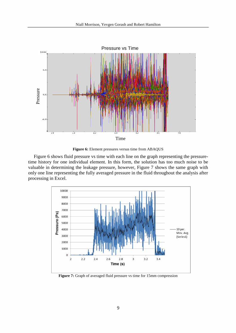
Figure 7: Graph of averaged fluid pressure vs time for 15mm compression
Pre
ssu
re
Time
Pressure vs Time

Niall Morrison, Yevgen Gorash and Robert Hamilton
10
The results presented in figure 7 allow for evaluation of the pressure-time behaviour of the
seal and quantify the pressure. At approximately 2.4 seconds the seal experiences an elastic
leak at a pressure of 4950 Pa followed by a continuous cycle of: Leak – Pressure drop – re-seal
– leak, which continues at a reduced pressure until the velocity of the piston increases, ramping
up the pressure to a point where the seal is lost from its housing at time approximately 3.3
seconds, See figure 8. This behaviour is consistent with experimental results obtained by Q Liu
[13] which act as an initial form of validation for the current results.
Figure 8: Loss of anchor points in seal at 15mm compression
3.2 Validation
Validation is essential for FE techniques as it relates the simulated model to the real world
and must be carried out to develop confidence in simulation results. One way of carrying out
basic validation is to compare results with, alternative, well validated FE techniques. As
experimental validation is expensive, a comparative study was chosen for this report.
The CEL results shown in Figure 5 were validated against a well-established leakage
prediction technique – Fluid Pressure Penetration interaction (FPP). FPP works by propagating
fluid pressure into the contact region to simulate leakage. The technique was used and
successfully validated by W Dearman for a similar application [14]. Figure 5 shows a
comparison of both analysis techniques and validates the accuracy of the CEL technique for the
range of compression levels resulting in average difference between the techniques of about
6%. Individual leakage prediction pressures for FPP can be found in Table 2.
The FPP simulation was carried out using an identical setup to the implicit pre-stretch
analysis to give the same initial configurations and contact conditions. An additional analysis
step was then added to accommodate the use of the fluid pressure penetration interaction which
is coupled to each of the surface contacts. FPP then applied the applied the fluid pressure to the
outer surface of the seal causing deformation until leakage. One advantage of this technique is
the reduced computational time when compared with CEL, implicit FPP simulations have a
duration of less than 10 minutes in the case presented here.

Niall Morrison, Yevgen Gorash and Robert Hamilton
11
4 DISCUSSION
The results obtained show that blow off pressure will increase with increasing compression
and that the increase is not linear. These results are expected and prove that the CEL technique
is capable of analysing leakage of an elastomeric seal and will provide realistic results given
the correct boundary conditions. The results from different compression levels show a variety
of leakage mechanisms when analysed individually, such as continuous leakage, loss of one
anchor point in the housing and more violent loss of both anchor points at the higher end of the
compression scale.
The validation carried out confirms the accuracy of the technique when compared with an
alternative, well established, leakage pressure prediction technique (FPP).
8 CONCLUSION
The findings of this project suggest that the future of leakage prediction may lie in the use
of the Coupled Eulerian-Lagrangian technique as it has many benefits over the alternatives. Not
only does this technique allow prediction of critical leakage pressure or blow off pressure, it
also allows for observation of the behaviour of seals after leakage occurs which will allow for
more efficient optimisation of seal design. CEL offers valuable visualisation of leakage
mechanisms which enables designers to identify target areas for improvement. Applying this
design methodology to the seal considered here, the designer may observe the extrusion of the
seal through the gap and solve this issue with more robust anchor points or seal retention rings.
There are limitations to this technique such as large computational time and solution noise.
Therefore, future work will aim to improve post processing and investigate techniques to reduce
noise in the solution such as slightly compressible material models for the operating fluid.
Alternatively, both analysis methods considered in this project may be used in conjunction to
accurately describe the initial leak pressure and the post leak behaviour of the seal. The FPP
technique is more efficient at predicting initial leakage pressure but does not provide any
indication of post-leak behaviour, whereas CEL is not as effective at prediction of initial
leakage pressure but is very effective in analysing post-leak behaviour. The use of both
techniques provides a more comprehensive view of seal behaviour under all operating
conditions.
Additionally, experimental validation of this technique would be extremely valuable when
considering the accuracy of the simulated results before application to more costly and complex
applications.
REFERENCES
[1] Simulia (2017) “SIMULIA User Assistance 2017 > Abaqus > Analysis > Analysis
Techniques > Eulerian Analysis Techniques (Version 2017)” Providence, RI, USA:
Dassault Systèmes Simulia Corp
[2] Morlacchi, S. (2015), “Compression and Stress Relaxation of a viscoelastic rubber seal”,
Simuleon > Knowledge Centre > Abaqus Tutorial No. 21, Bruchem, Netherlands:
Simuleon B.V.

Niall Morrison, Yevgen Gorash and Robert Hamilton
12
[3] Simulia – Dassualt Systemes (2013), 12.2.1 ALE adaptive meshing: overview,
http://abaqus.software.polimi.it/v6.13/books/usb/default.htm?startat=pt04ch12s02aus78.
html (Accessed 9 March 2018)
[4] ABAQUS Inc. (2005), Overview of ABAQUS/Explicit, Website:
http://imechanica.org/files/0-overview%20Explicit.pdf (Accessed 05/01/2018)
[5] G Qiu (2011), Application of a Coupled Eulerian–Lagrangian approach on geomechanical
problems involving large deformations, January 2011 [cited 2018 March 2], Computers
and Geotechnics, Vol. 38 Issue 1, Pages 30-39; Available from: https://www-
sciencedirect-
com.proxy.lib.strath.ac.uk/science/article/pii/S0266352X10001175?via%3Dihub
[6] Li, Kun ; Jarrar, Firas ; Sheikh-Ahmad, Jamal ; Ozturk, Fahrettin (2017), Using coupled
Eulerian Lagrangian formulation for accurate modeling of the friction stir welding
process, Procedia Engineering, 2017 [Cited 2018 March 2], Vol.207, pp.574-579;
available from:
https://www.sciencedirect.com/science/article/pii/S1877705817358162?via%3Dihub
[7] L Foucard et al (2015), A coupled Eulerian–Lagrangian extended finite element formulation
for simulating large deformations in hyperelastic media with moving free boundaries,
Computer Methods in Applied Mechanics and Engineering, 1 January 2015 [Cited 2018
March 2], Vol.283, pp.280-302; Available from: https://www-sciencedirect-
com.proxy.lib.strath.ac.uk/science/article/pii/S0045782514003314?via%3Dihub
[8] Morlacchi, S. (2014), “CEL model of a boat in a wavy sea”, Simuleon > Knowledge Centre
> Abaqus Tutorial No. 17, Bruchem, Netherlands: Simuleon B.V.
https://cdn2.hubspot.net/hubfs/542635/Tutorials/Tutorial_17_-_CEL_-_Boat.pdf
(Accessed 12/01/2018)
[9] Treloar, L.R.G. (1944), “Stress-strain data for vulcanised rubber under various types of
deformation”, Transactions of the Faraday Society, vol. 40, pages 59-70.
[10] Dassault Systemes (2012), “Abaqus 6.12 Example Problems Manual, Volume I: Static
and Dynamic Analyses”, Pages. 711, 2.1.12-2; Available from:
http://abaqus.software.polimi.it/v6.12/pdf_books/EXAMPLES_1.pdf
[11] Y Gorash, T Comlekci, R Hamilton (2017), "CAE-Based application for identification
and verification of hyper-elastic parameters", Proceedings of the Institution of Mechanical
Engineers, Part L: Journal of Materials: Design and Applications, 231 (7), pp. 611-626
[12] Multiscale Consulting, “Rubber friction | Research”, Website:
http://www.multiscaleconsulting.com/our-research/rubber-friction (Accessed
18/12/2017)
[13] Q Liu, Z Wang (2014), “Elastic leak of a seal”, [cited 2018 March 12], Extreme Mechanics
Letters, Vol. 1, Pages 54-61; Available from:
https://www.sciencedirect.com/science/article/pii/S2352431614000029
[14] W Dearman (2017), Fraser Nash Consultancy, “Finite Element Analysis of Rubber
Subsea Airlock Seal”, in proceedings of SIMULIA UK Regional User Meeting, Cheshire
UK, October 18-19