Embed Size (px)
Citation preview
ECE 340 Lecture 32 : Introduction to
the BJT-I
Class Outline: • BJT Fundamentals • BJT Amplification
• How can a transistor function as both a switch and an amplifier? • What are the main
characteristics of a BJT? • What are the main mechanisms
for current flow? M.J. Gilbert ECE 340 – Lecture 32 11/12/12
Things you should know when you leave…
Key Questions
M.J. Gilbert ECE 340 – Lecture 32 11/12/12
BJT Fundamentals
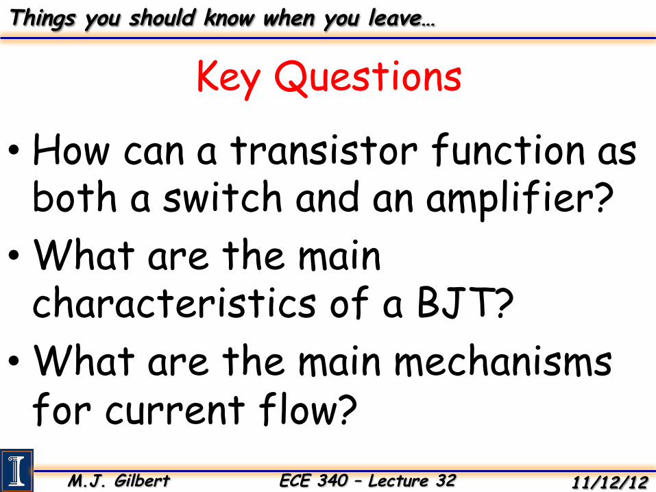
Before we proceed with our discussion of the BJT, we should discuss transistor operation in general… What is a transistor? • Three terminal device.
• Current flowing through two terminals can be controlled by the application of voltages to the third terminal.
This will allow us to perform the following very important functions: • The amplification of a small AC signal. • Switch the device from an “on” state to an “off” state. P-‐MOS
N-‐MOS
Input (A) Output (Q)
1 (Vdd) 0 (Vss)
0 (Vss) 1 (Vdd)
Remember the inverter…
M.J. Gilbert ECE 340 – Lecture 32 11/12/12
BJT Fundamentals
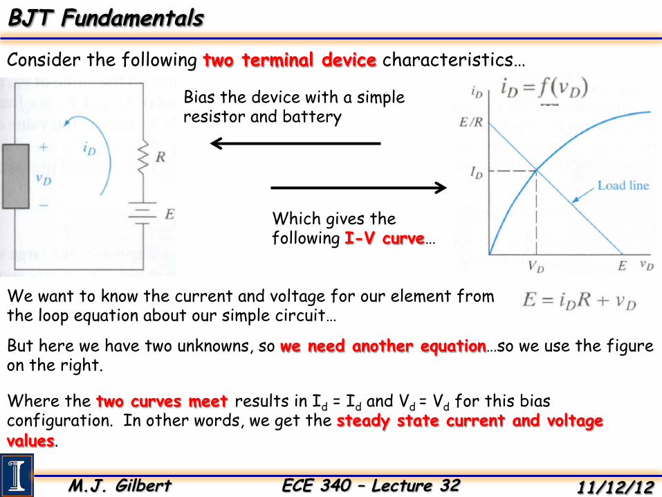
Consider the following two terminal device characteristics…
Which gives the following I-V curve…
Bias the device with a simple resistor and battery
We want to know the current and voltage for our element from the loop equation about our simple circuit…
But here we have two unknowns, so we need another equation…so we use the figure on the right.
Where the two curves meet results in Id = Id and Vd = Vd for this bias configuration. In other words, we get the steady state current and voltage values.
M.J. Gilbert ECE 340 – Lecture 32 11/12/12
BJT Fundamentals
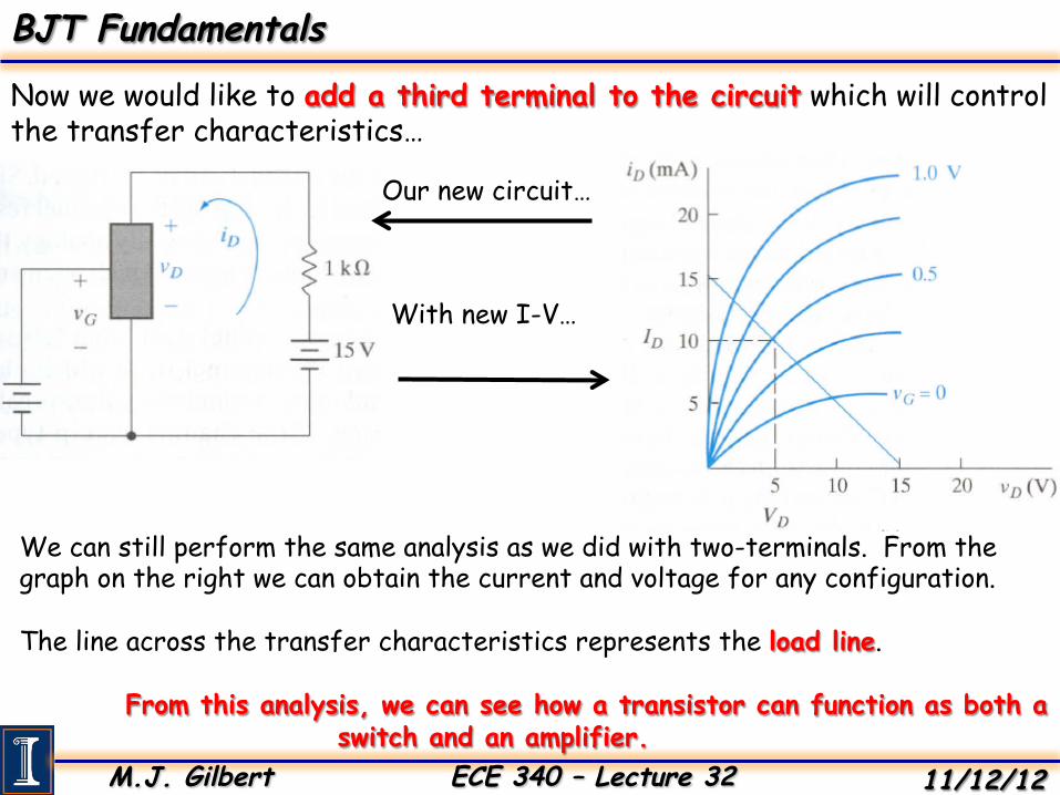
Now we would like to add a third terminal to the circuit which will control the transfer characteristics…
Our new circuit…
With new I-V…
We can still perform the same analysis as we did with two-terminals. From the graph on the right we can obtain the current and voltage for any configuration. The line across the transfer characteristics represents the load line.
From this analysis, we can see how a transistor can function as both a switch and an amplifier.
M.J. Gilbert ECE 340 – Lecture 32 11/12/12
BJT Fundamentals
Now we may begin our analysis of the Bipolar Junction Transistor (BJT)…
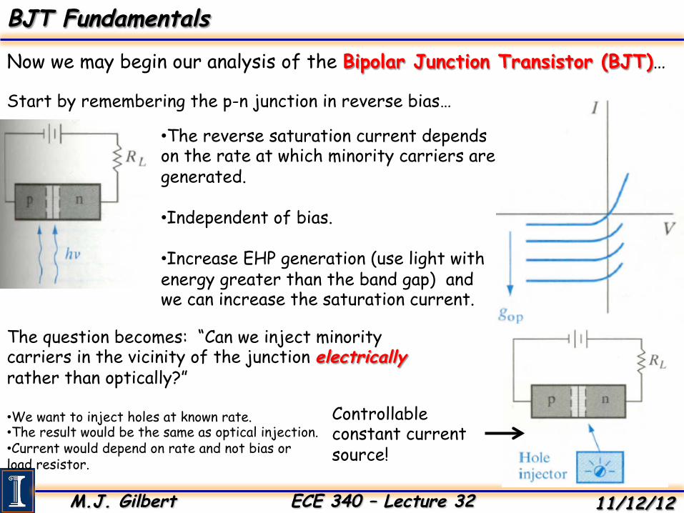
Start by remembering the p-n junction in reverse bias…
• The reverse saturation current depends on the rate at which minority carriers are generated. • Independent of bias.
• Increase EHP generation (use light with energy greater than the band gap) and we can increase the saturation current.
The question becomes: “Can we inject minority carriers in the vicinity of the junction electrically rather than optically?”
• We want to inject holes at known rate. • The result would be the same as optical injection. • Current would depend on rate and not bias or load resistor.
Controllable constant current source!
M.J. Gilbert ECE 340 – Lecture 32 11/12/12
BJT Fundamentals
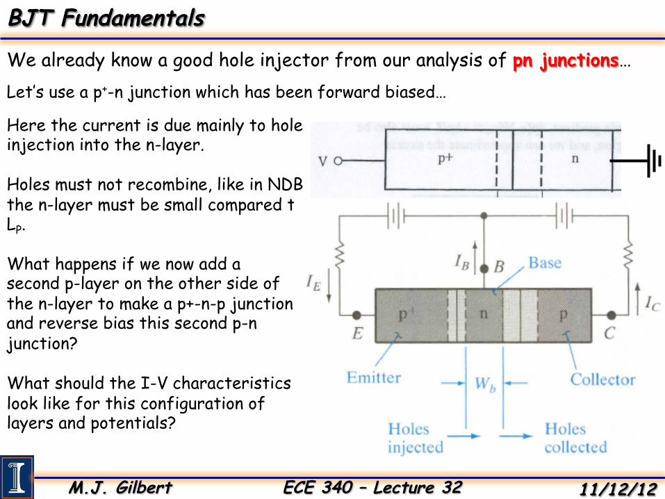
We already know a good hole injector from our analysis of pn junctions… Let’s use a p+-n junction which has been forward biased…
Here the current is due mainly to hole injection into the n-layer. Holes must not recombine, like in NDB the n-layer must be small compared to LP.
What happens if we now add a second p-layer on the other side of the n-layer to make a p+-n-p junction and reverse bias this second p-n junction? What should the I-V characteristics look like for this configuration of layers and potentials?
M.J. Gilbert ECE 340 – Lecture 32 11/12/12
BJT Fundamentals
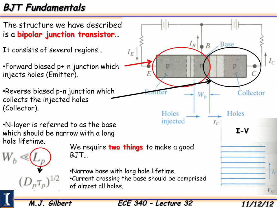
The structure we have described is a bipolar junction transistor…
It consists of several regions… • Forward biased p+-n junction which injects holes (Emitter).
• Reverse biased p-n junction which collects the injected holes (Collector).
• N-layer is referred to as the base which should be narrow with a long hole lifetime.
We require two things to make a good BJT… • Narrow base with long hole lifetime. • Current crossing the base should be comprised of almost all holes.
I-V
M.J. Gilbert ECE 340 – Lecture 32 11/12/12
BJT Fundamentals
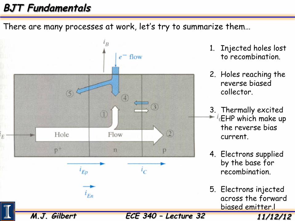
There are many processes at work, let’s try to summarize them…
1. Injected holes lost to recombination.
2. Holes reaching the reverse biased collector.
3. Thermally excited EHP which make up the reverse bias current.
4. Electrons supplied by the base for recombination.
5. Electrons injected across the forward biased emitter.l
M.J. Gilbert ECE 340 – Lecture 32 11/12/12
BJT Fundamentals
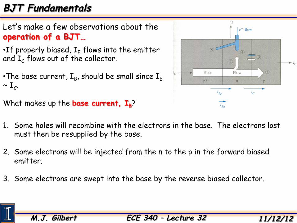
Let’s make a few observations about the operation of a BJT… • If properly biased, IE flows into the emitter and IC flows out of the collector.
• The base current, IB, should be small since IE ~ IC.
What makes up the base current, IB?
1. Some holes will recombine with the electrons in the base. The electrons lost must then be resupplied by the base.
2. Some electrons will be injected from the n to the p in the forward biased emitter.
3. Some electrons are swept into the base by the reverse biased collector.
M.J. Gilbert ECE 340 – Lecture 32 11/12/12
Amplification with BJTs
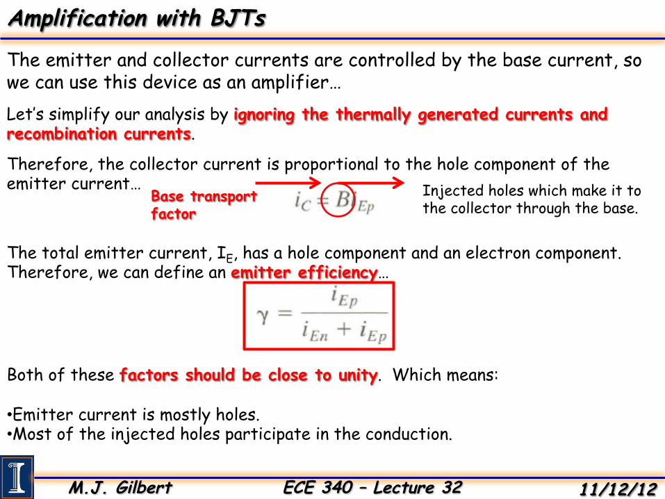
The emitter and collector currents are controlled by the base current, so we can use this device as an amplifier… Let’s simplify our analysis by ignoring the thermally generated currents and recombination currents.
Therefore, the collector current is proportional to the hole component of the emitter current… Injected holes which make it to
the collector through the base. Base transport factor
The total emitter current, IE, has a hole component and an electron component. Therefore, we can define an emitter efficiency…
Both of these factors should be close to unity. Which means: • Emitter current is mostly holes. • Most of the injected holes participate in the conduction.
M.J. Gilbert ECE 340 – Lecture 32 11/12/12
Amplification with BJTs
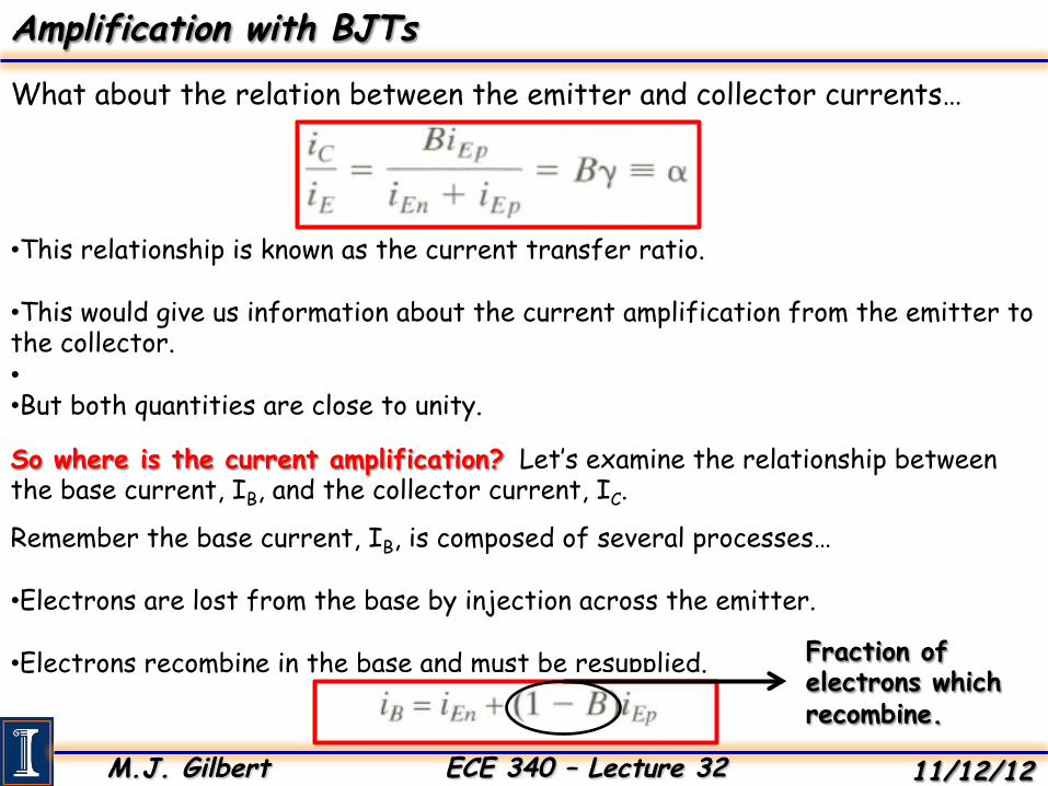
What about the relation between the emitter and collector currents…
• This relationship is known as the current transfer ratio.
• This would give us information about the current amplification from the emitter to the collector. • • But both quantities are close to unity.
So where is the current amplification? Let’s examine the relationship between the base current, IB, and the collector current, IC.
Remember the base current, IB, is composed of several processes… • Electrons are lost from the base by injection across the emitter.
• Electrons recombine in the base and must be resupplied. Fraction of electrons which recombine.
M.J. Gilbert ECE 340 – Lecture 32 11/12/12
Amplification with BJTs
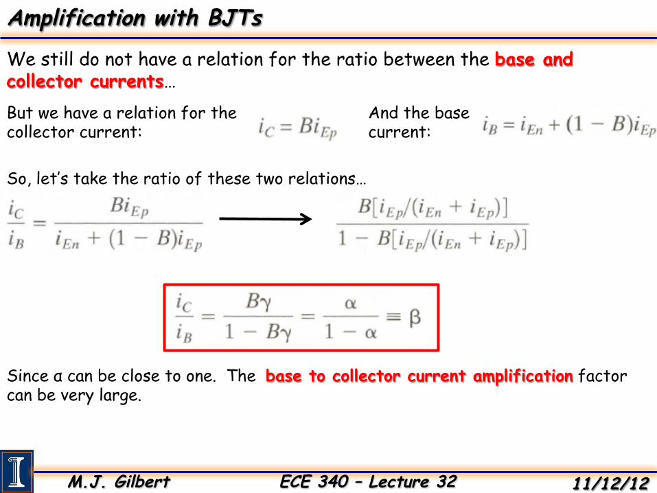
We still do not have a relation for the ratio between the base and collector currents… But we have a relation for the collector current:
And the base current:
So, let’s take the ratio of these two relations…
Since α can be close to one. The base to collector current amplification factor can be very large.
M.J. Gilbert ECE 340 – Lecture 32 11/12/12
Amplification with BJTs
But what does this matter?
• We have made an argument that we need a three terminal device where the third terminal can control the magnitude of the output.
• We have seen that the emitter current can control the collector current.
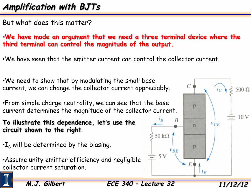
• We need to show that by modulating the small base current, we can change the collector current appreciably.
• From simple charge neutrality, we can see that the base current determines the magnitude of the collector current. To illustrate this dependence, let’s use the circuit shown to the right. • IB will be determined by the biasing. • Assume unity emitter efficiency and negligible collector current saturation.
M.J. Gilbert ECE 340 – Lecture 32 11/12/12
Amplification with BJTs
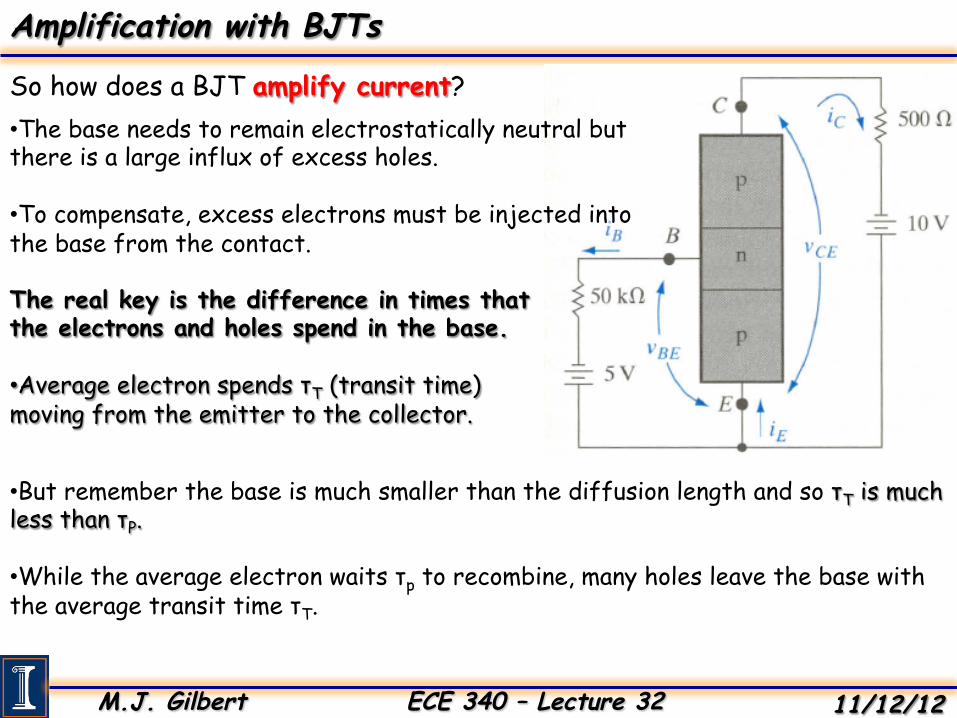
So how does a BJT amplify current? • The base needs to remain electrostatically neutral but there is a large influx of excess holes. • To compensate, excess electrons must be injected into the base from the contact.
The real key is the difference in times that the electrons and holes spend in the base. • Average electron spends τT (transit time) moving from the emitter to the collector.
• But remember the base is much smaller than the diffusion length and so τT is much less than τP.
• While the average electron waits τp to recombine, many holes leave the base with the average transit time τT.
M.J. Gilbert ECE 340 – Lecture 32 11/12/12
Amplification with BJTs
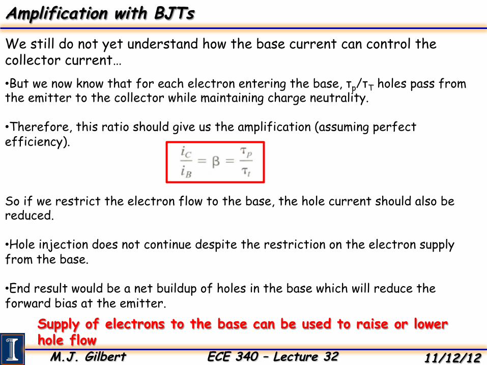
We still do not yet understand how the base current can control the collector current… • But we now know that for each electron entering the base, τp/τT holes pass from the emitter to the collector while maintaining charge neutrality. • Therefore, this ratio should give us the amplification (assuming perfect efficiency).
So if we restrict the electron flow to the base, the hole current should also be reduced. • Hole injection does not continue despite the restriction on the electron supply from the base.
• End result would be a net buildup of holes in the base which will reduce the forward bias at the emitter.
Supply of electrons to the base can be used to raise or lower hole flow
M.J. Gilbert ECE 340 – Lecture 32 11/12/12
Amplification with BJTs
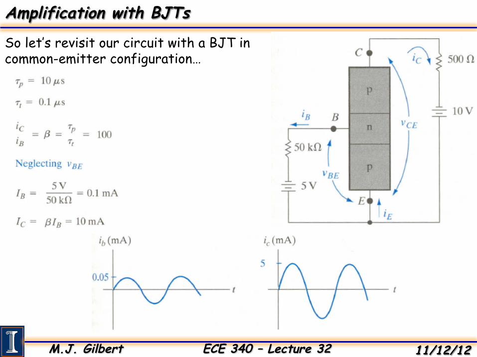
So let’s revisit our circuit with a BJT in common-emitter configuration…