Embed Size (px)
Citation preview

ECE 416Comprehensive Design ReviewTeam 26 - UParkMarch 31st, 2021
1

Meet the Team (Again!)
● Rehmat Kang○ Computer Engineering
● Belma Kondi○ Electrical Engineering
● Nikhil Sarecha○ Computer Engineering
● Lastone Saya○ Electrical Engineering
● Prof. Christopher Hollot● Faculty Advisor
2

UPark - an RFID-based Smart Parking Payment System
3

Problem Statement
The UMass Campus has several methods of parking payment services. These methods expect the user to either purchase a permit, carry loose change, or even install a third-party application. Overall, these different forms of payment methods make it cumbersome for the user as well as the administrator to monitor parking transactions. There exists a more convenient way with UPark.
Our SolutionWe aim to solve the problem of inconsistency by introducing the use of RFID transponders, in vehicles on campus. These transponders will communicate with RFID readers at distinctive entrances and exits of parking lots across campus and charge the users accordingly. The whole parking payment process is now seamless and contactless, and managed by a centralized parking control system which allows users to track their logs.
4
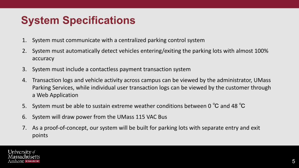
1. System must communicate with a centralized parking control system
2. System must automatically detect vehicles entering/exiting the parking lots with almost 100% accuracy
3. System must include a contactless payment transaction system
4. Transaction logs and vehicle activity across campus can be viewed by the administrator, UMass Parking Services, while individual user transaction logs can be viewed by the customer through a Web Application
5. System must be able to sustain extreme weather conditions between 0 ℃ and 48 ℃
6. System will draw power from the UMass 115 VAC Bus
7. As a proof-of-concept, our system will be built for parking lots with separate entry and exit points
System Specifications
5

Illustration Of UPark
RFID Reader
RFID Tag
Represented above are the different entry and exit points of a parking lot. An RFID Reader installed at this location will detect RFID tags, embedded in the UMass Parking Stickers in vehicles entering/exiting to activate a clock timer accordingly, which will calculate the cost.
With UPark, we aim to eliminate the need for users to stop at the entry point to generate a ticket or be required to pay for parking manually.
RFID Reader
RFID Tag
6

Block Diagram
W
Parking Lot Module
UMass 115VAC
Bus
RFID Tag PCB
ReaderModule
Web App● Transaction Log● Parking Map● Payment
Notification● Current Balance
WiFi Module
Antennas
Cloud
Compute Cloud Database Website
hosting
USER
Microcontroller
RFID Reader AC to DC Converter
7
Antenna

System Design
5V DC Supply
Sparkfun M6e Nano RFID Reader
Atmel 328P Microcontroller
Feather Huzzah ESP8266 WiFi
Cloud
Web App
Other Parking Lot Modules
RFID Reader (Active)RFID Tag (Passive)
WRL14131 Antenna AWS Lambda AWS DynamoDB
SPIconnection
8
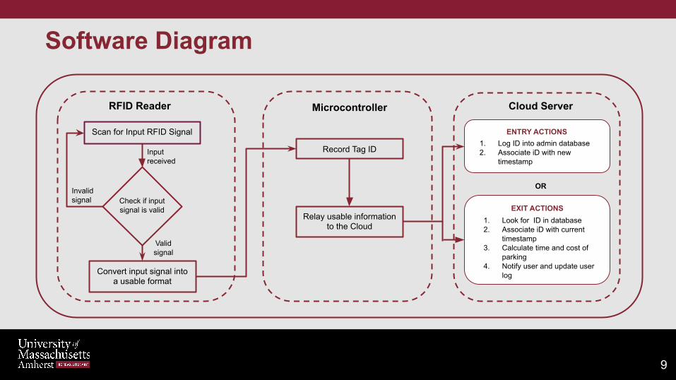
Software Diagram
RFID Reader Microcontroller Cloud Server
Record Tag ID
Convert input signal into a usable format
Relay usable information to the Cloud
Check if input signal is valid
Scan for Input RFID Signal
Invalid signal
ENTRY ACTIONS
EXIT ACTIONS
1. Log ID into admin database2. Associate iD with new
timestamp
Valid signal
1. Look for ID in database2. Associate iD with current
timestamp3. Calculate time and cost of
parking4. Notify user and update user
log
OR
Input received
9

• End-to-end integration of the two subcomponents to perform the entire cycle of operations for a vehicle entering and exiting a parking lot
Delivered:1. Prototype will be able pick up an incoming RFID signal via the RFID module2. The RFID tag data will be sent over to the microcontroller via serial communication3. Microcontroller will parse through the tag data and send it through the WiFi module
over to the Cloud server to log into databaseIn Progress:4. Database will determine entry or exit based on previous data log and calculate
parking time and cost accordingly5. The calculated cost will be reflected on admin database and user’s GUI profile in real
time
CDR Deliverables
10

Integrated System Demonstration
11
RFID Tag
Arduino Uno Controller
Read/Write ControlRead Data Processing
RC522 RFID Reader ModuleM6E Nano RFID
Reader Module + Antenna
ESP8266 WiFi Module
AWS ServerDisplay:
Active Tag DataProcess:
Tag Data for cost calculation and GUI
User GUI
Active RFID Input Data
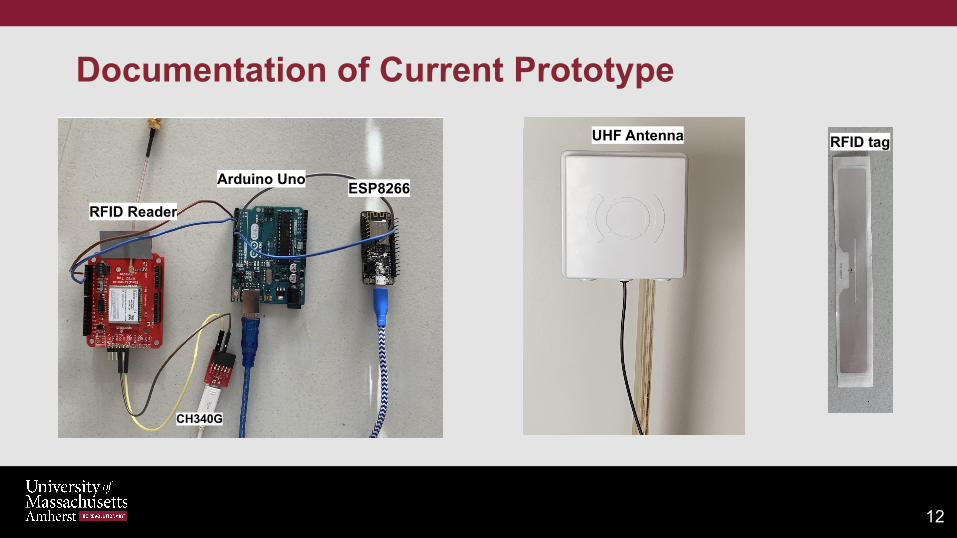
Documentation of Current Prototype
12
RFID ReaderESP8266
CH340G
Arduino Uno
UHF Antenna RFID tag

CDR Demo
13

PCB Schematic
14
Modules
● Voltage regulators● Wifi Module● Power module● Atmega328p

LM2937 voltage regulator 3.3v
Voltage Regulators
15
7805 voltage regulator with 5v output

ATMega328p
16
● Operate with a voltage of 5v● Communicate with the RFID
reader and the wifi module ● An LED is installed and
connected to pin19 and GND
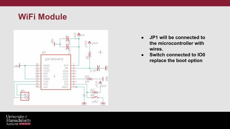
● JP1 will be connected to the microcontroller with wires.
● Switch connected to IO0 replace the boot option
WiFi Module
17

PCB Final Form
18
Top Side
Bottom Side

1. End-to-end integration to perform the entire cycle of operations for a vehicle entering and exiting a parking lot
• (Entire team)2. Transition from the Arduino Uno to bare-metal ATMega 328P
• (Belma)3. Have PCB tested and integrated into final product
• (Lastone)4. Optimize cloud infrastructure for necessary backend processing
operations• (Rehmat)
5. Complete building a functional GUI interacting dynamically with AWS• (Nikhil)
6. Switch from Feather HUZZAH WiFi Module to ESP-WROOM-02a. (Rehmat + Nikhil)
Primary Responsibilities for FPR
19
Hardware Plans for FPR
• Transition from Arduino Uno to ATmega328P
• Have PCB integrated with system
• Switch from ESP8266 to ESP-WROOM-02 wifi module
20

• Current Prototype Includes: • Arduino Uno• Feather HUZZAH ESP8266 WiFi Module
• Final Project at FPR will include:• PCB, with ATMega328P microcontroller and ESP-WROOM-02 WiFi Module• Housing unit for the RFID Module, PCB, and Antenna
• Plan for testing the system for compliance with system specifications:• Attach RFID tags to the side windows of car(s)• Gather data of test cases of vehicle moving at different speeds, tags placed at
different heights/distances from the reader.
FPR Plan
21

Project Management: Responsibilities
● Lastone Saya - Altium Lead○ RFID Reader and Microcontroller
● Belma Kondi - Budget Lead○ RFID Reader and Microcontroller
● Rehmat Kang○ Microcontroller and WiFi Module
● Nikhil Sarecha - Team Coordinator ○ Web Server and GUI
22

Project Expenditures (Current & Projected)
23
Projected Expenditures Cost
PCB Components $30
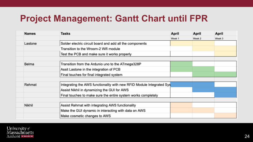
Project Management: Gantt Chart until FPR
24

Thank You! Any Questions?
25