Embed Size (px)
Citation preview

ECE 4710: Lecture #21 1
Frequency Modulation
Overview: Mathematical analysis of FM signal & spectrum is very complicated FM is normally a wideband modulation method where
BFM >> baseband signal B» Spectrally inefficient
FM is a non-linear modulation method» AM & DSB-SC are linear methods
Non-linear method allows one to trade RF signal BW for non-linear increase in Rx S/N» Power for bandwidth tradeoff
FM is the most widely used analog modulation method for mobile radio used extensively from 1940-present day
Spectrally efficient digital methods have replaced FM in many mobile radio applications (e.g. cellular)» Congested spectrum requires spectral efficiency for large user populations

ECE 4710: Lecture #21 2
Frequency Modulation
Complex envelope for phase modulation (PM) and frequency modulation (FM) is: The real envelope R(t) = | g(t) | = Ac constant value PM and FM are constant envelope modulation methods
» AM & DSB-SC are linear since R(t) is linearly to m(t) Bandpass signal is: Relationship between (t) & m(t) determines type of
modulation PM or FM For PM we have
» Linear relationship between phase and modulating signal» Still nonlinear modulation since:
)()( tjceAtg
)](2cos[)( ttfAts cc
}Re{)( )(2 tmjDtfjc
pc eeAts
)()( tmDt p

ECE 4710: Lecture #21 3
Frequency Modulation
In the constant Dp is the phase sensitivity of the phase modulator with units of rad/V Larger Dp means greater phase change in s(t) for every
volt of m(t) assuming m(t) is voltage signal FM is a special case of PM
Frequency is the time derivative of phase: So
Let Df = frequency deviation constant with units rad/V•s then
)()( tmDt p
dtdf
dtftdtfd )( then and
dmDtt
f )()(
rad/s are units )(
abledummy vari
mD f

ECE 4710: Lecture #21 4
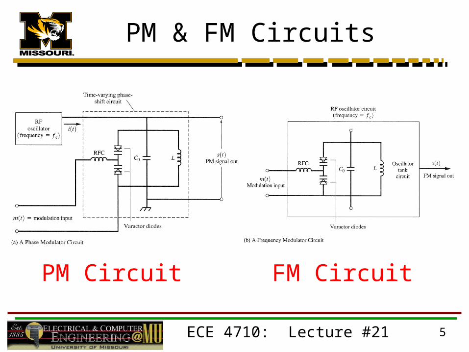
PM & FM Circuits
PM circuit pass unmodulated RF signal through circuit that introduces time variation in phase
FM circuit vary frequency of tuned RF oscillator circuit by varying resonant frequency of the circuit
Varactor diodes have variable capacitance controlled by amount of voltage applied across diode Time varying capacitance used to generate time-varying
phase for PM and time-varying frequency for FM
ECE 4710: Lecture #21 5
PM & FM Circuits
PM Circuit FM Circuit

ECE 4710: Lecture #21 6
PM & FM
PM: and FM: So and
Integrator and differentiator circuits (op-amp) can be used on baseband m(t) to generate PM from FM and vice versa
Integrator + PM circuit = FM output Differentiator + FM circuit = PM output
dmDtt
ff )()( )()( tmDt pp
dmDtmDt
ffpp )()(
t
fp
fp
p
f
pf dm
D
Dtm
dt
tdm
D
Dtm )()( and
)()(

ECE 4710: Lecture #21 7
Frequency Modulation
For this class we are mainly interested in FM since it is the most widely used analog modulation method in the world analog mobile radio
Bandpass signal & Instantaneous frequency of s(t) is
and for FM we have
)](2cos[)( ttfAts cc dtdf
dttd
ftf ci
)(21
)(
)(21
)( tmDftf fci
Instantaneous frequency varies in time about assigned carrier frequency by an amount determined by Df and modulating
information signal m(t)

ECE 4710: Lecture #21 8
Frequency Modulation
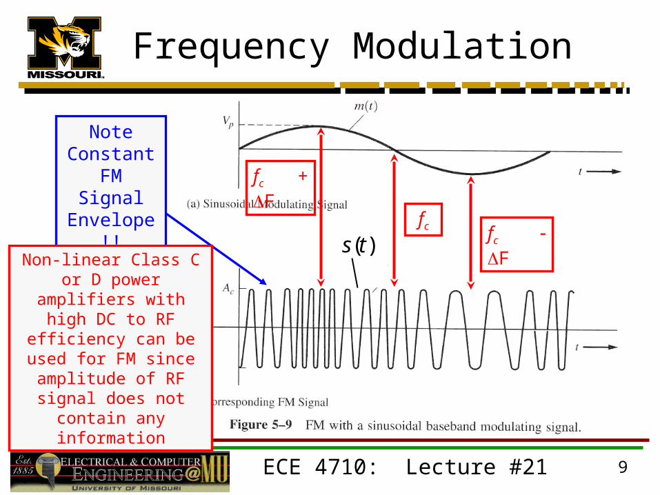
For illustration purposes assume m(t) is sinusoidal:
F = peak frequency deviation
ECE 4710: Lecture #21 9
Frequency Modulation
fc + F
fc F
Note Constant FM Signal Envelope!!
Non-linear Class C or D power amplifiers with high DC to RF efficiency can
be used for FM since amplitude of RF signal does not contain any
information
fc
)(ts

ECE 4710: Lecture #21 10
Frequency Modulation
Instantaneous frequency Frequency of s (t) at specific point in time
Fourier Transform frequency
FT spectrum for s (t) is evaluated for interval < t < + FT spectrum represents frequency content of s (t) over all
time **average** frequency content Peak frequency deviation is given by
dttstsfS tfj 2exp)]([)]([)(
)](max[ where21
tmVVDF ppf

ECE 4710: Lecture #21 11
Frequency Modulation
Peak frequency deviation related to RF signal BW
Increasing amplitude of modulating signal (Vp) increases F and RF
signal BW
» Spectral components appear farther an farther away from fc
Note that average power of FM signal is constant value =» Independent of FM signal BW
As BW the spectral components near fc must decrease in strength
since the average power remains constant
AM or DSB-SC increase in m(t) affects Tx output power but not RF signal BW
FM increase in m(t) affects RF signal BW but not Tx output power
)](max[ where21
tmVVDF ppf
2/2cA

ECE 4710: Lecture #21 12
Frequency Modulation
Frequency modulation index: B is absolute bandwidth of m(t) For sinusoidal m(t) B = fm sinusoid frequency Sinusoidal modulation is often used for demonstration
purposes and simplified calculations Actual m(t) is usually non-deterministic (e.g. voice)
FM signal spectrum
and g(t) is nonlinear function of m(t) no general relationship
relating G(f ) to M(f ) !! evaluated on case by case basis for deterministic waveforms only
B
VD
BF pf
f
2
)()()( *21
cc ffGffGfS
t
f dmDj
c
tj
ceAeAtgfG
)()( ][)]([)(

ECE 4710: Lecture #21 13
FM Signal Spectrum
Assume sinusoidal modulation signal:where
Complex envelope is:
Baseband signal spectrum can be shown to be:
Infinite series line spectrum (e.g. ) spaced by fm with amplitudes determined by first order Bessel functions Jn ()» Jn () can only be evaluated numerically
)2cos()( tfAtm mmf
2 and
2mf
fmfm
mff
ADfBF
f
AD
BF
)2sin()2cos()()()( tfjc
dfADj
c
dmDj
ctj
cmf
t
mmf
t
feAeAeAeAtg
n
mnc nffJAfG )()()(

ECE 4710: Lecture #21 14
Bessel Functions
n
mnc nffJAfG )()()(
1. Note that for f = fc n = 0
2. Carrier spectral amplitude is J0 ()
3. Modulation index determines carrier
strength
4. can be selected such that J0 ()
e.g. = 2.4, 5.5, etc.

ECE 4710: Lecture #21 15
FM Signal Spectrum
2.0BF
f
0.1BF
f
0.2BF
f

ECE 4710: Lecture #21 16
FM Signal Spectrum
0.5f
0.8f

ECE 4710: Lecture #21 17
FM Signal Spectrum
RF signal BW depends on f and B Computation of RF signal BW using standard
definitions (3-dB BW) is very difficult for anything but simplified m(t) sinusoidal Computer computations for non-deterministic waveforms
(data, voice, etc.) Carson’s rule approximate BW for 98% total
power Simple and therefore very useful Widely used rather than computational approach for
estimating signal BW
BB fT )1(2