Embed Size (px)
Citation preview
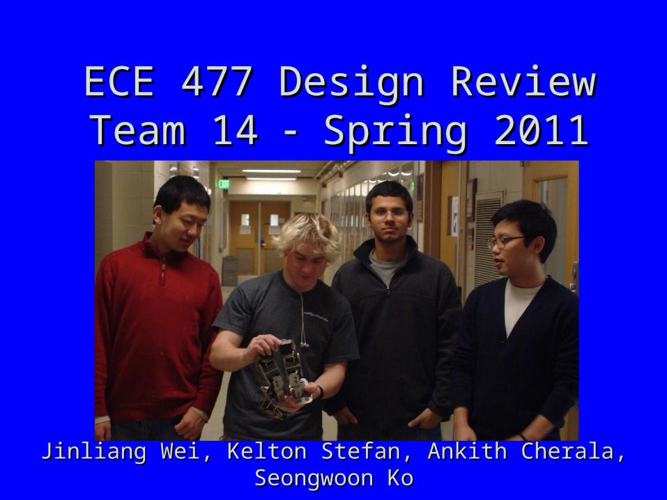
ECE 477 Design Review ECE 477 Design Review Team 14 Team 14 Spring 2011 Spring 2011
Paste a photo of team members here, annotated with names of team members.
Jinliang Wei, Kelton Stefan, Ankith Cherala, Seongwoon KoJinliang Wei, Kelton Stefan, Ankith Cherala, Seongwoon Ko
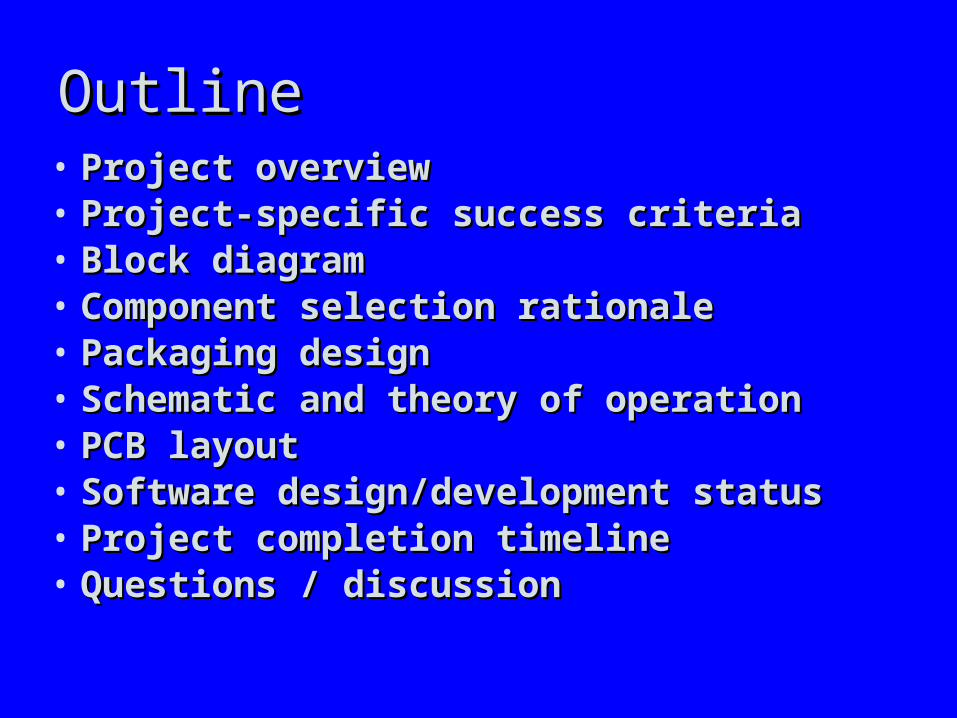
OutlineOutline• Project overview Project overview • Project-specific success criteriaProject-specific success criteria• Block diagramBlock diagram• Component selection rationaleComponent selection rationale• Packaging designPackaging design• Schematic and theory of operationSchematic and theory of operation• PCB layoutPCB layout• Software design/development statusSoftware design/development status• Project completion timelineProject completion timeline• Questions / discussionQuestions / discussion
Project OverviewProject Overview
• Self-balancing Biped Robot is a robot that Self-balancing Biped Robot is a robot that performs basic functionalities of human legs, performs basic functionalities of human legs, such as moving and changing directions. such as moving and changing directions. While utilizing 4 servos on each leg during While utilizing 4 servos on each leg during motion, our robot would receive instructions motion, our robot would receive instructions from a controlling software (GUI) using from a controlling software (GUI) using wireless communication. The goal of this wireless communication. The goal of this project is to modify and use a pair of robotic project is to modify and use a pair of robotic legs to achieve desired motion.legs to achieve desired motion.
Project-Specific Success CriteriaProject-Specific Success Criteria
• An ability for the robot to balance itselfAn ability for the robot to balance itself• An ability for the robot to walk forwardAn ability for the robot to walk forward• An ability for the robot to “pivot”An ability for the robot to “pivot”• An ability for the robot to detect an obstacle An ability for the robot to detect an obstacle
in its forward path and “halt”in its forward path and “halt”• An ability to remotely control the robot’s An ability to remotely control the robot’s
operating modeoperating mode
Block DiagramBlock Diagram
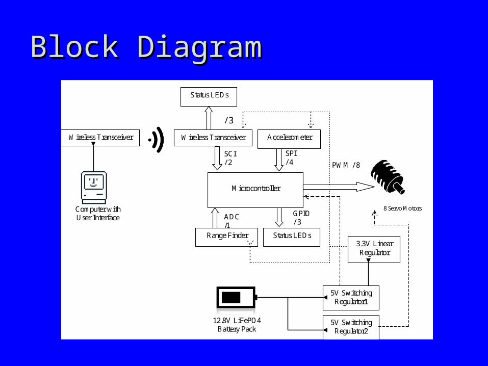
PWM / 8
SCI / 2
Computer with User Interface
GPIO / 3
12.8V LiFePO4 Battery Pack
8 Servo Motors
SPI / 4
ADC /1
Range Finder Status LEDs
Microcontroller
Wireless Transceiver Accelerometer Wireless Transceiver
5V Switching Regulator1
3.3V Linear Regulator
Status LEDs
/ 3
5V Switching Regulator2
Component Selection RationaleComponent Selection Rationale
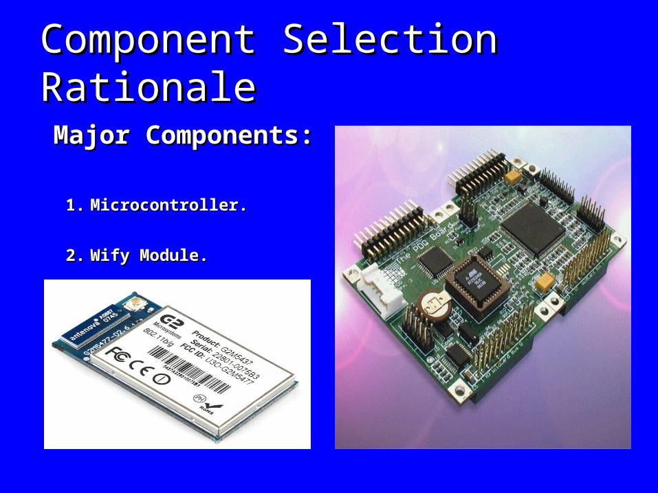
Major Components:Major Components:
1.1. Microcontroller.Microcontroller.
2.2. Wify Module.Wify Module.
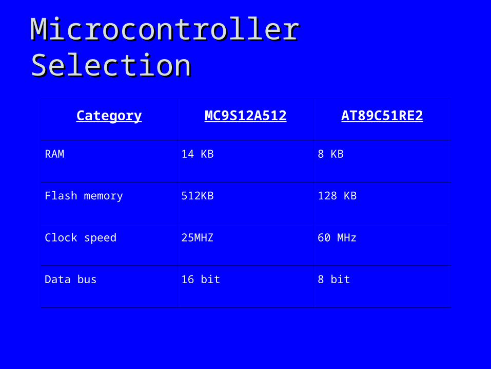
Microcontroller SelectionMicrocontroller Selection
Category MC9S12A512 AT89C51RE2
RAM 14 KB 8 KB
Flash memory 512KB 128 KB
Clock speed 25MHZ 60 MHz
Data bus 16 bit 8 bit
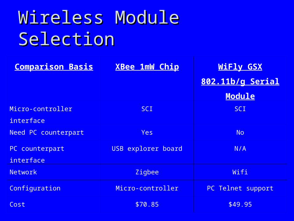
Wireless Module SelectionWireless Module Selection
Comparison Basis XBee 1mW Chip WiFly GSX 802.11b/g
Serial Module
Micro-controller interface SCI SCI
Need PC counterpart Yes No
PC counterpart interface USB explorer board N/A
Network Zigbee Wifi
Configuration Micro-controller PC Telnet support
Cost $70.85 $49.95
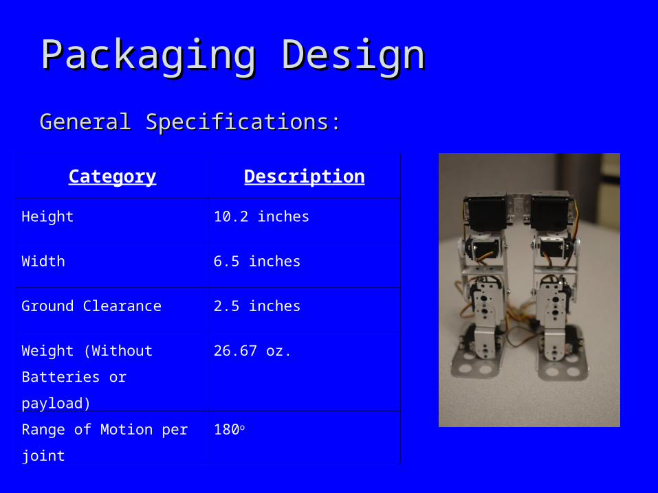
Packaging DesignPackaging Design
General Specifications:General Specifications:
Category Description
Height 10.2 inches
Width 6.5 inches
Ground Clearance 2.5 inches
Weight (Without Batteries or
payload)
26.67 oz.
Range of Motion per joint 180o
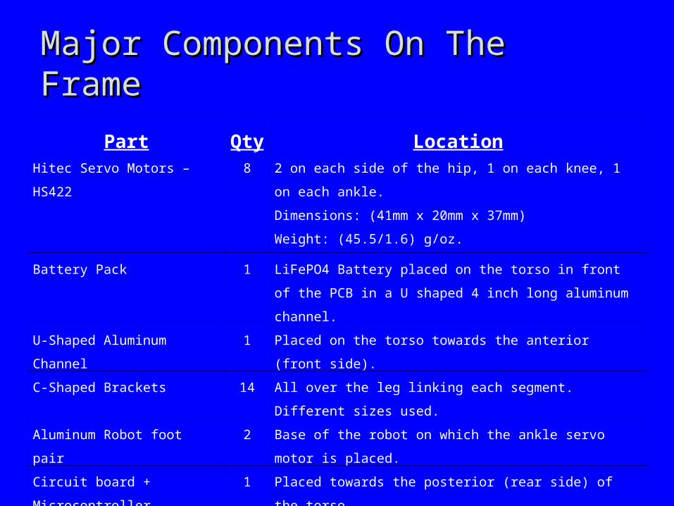
Major Components On The FrameMajor Components On The Frame
Part Qty LocationHitec Servo Motors – HS422 8 2 on each side of the hip, 1 on each knee, 1 on each ankle.
Dimensions: (41mm x 20mm x 37mm)
Weight: (45.5/1.6) g/oz.
Battery Pack 1 LiFePO4 Battery placed on the torso in front of the PCB in a U
shaped 4 inch long aluminum channel.
U-Shaped Aluminum Channel 1 Placed on the torso towards the anterior (front side).
C-Shaped Brackets 14 All over the leg linking each segment. Different sizes used.
Aluminum Robot foot pair 2 Base of the robot on which the ankle servo motor is placed.
Circuit board + Microcontroller 1 Placed towards the posterior (rear side) of the torso.
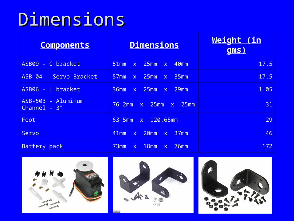
DimensionsDimensionsComponents Dimensions Weight (in gms)
ASB09 - C bracket 51mm x 25mm x 40mm 17.5
ASB-04 - Servo Bracket 57mm x 25mm x 35mm 17.5
ASB06 - L bracket 36mm x 25mm x 29mm 1.05
ASB-503 - Aluminum Channel - 3" 76.2mm x 25mm x 25mm 31
Foot 63.5mm x 120.65mm 29
Servo 41mm x 20mm x 37mm 46
Battery pack 73mm x 18mm x 76mm 172
Positive Aspects of PackagingPositive Aspects of Packaging
• The robot can turn to the side without walking.The robot can turn to the side without walking.
• PCB assures connection to various components PCB assures connection to various components while fitting in a compact area.while fitting in a compact area.
• Wide robot’s foot would help in maintaining stability.Wide robot’s foot would help in maintaining stability.
• PCB is shielded.PCB is shielded.
• PCB is fixed to the U-shaped aluminum channel. PCB is fixed to the U-shaped aluminum channel.
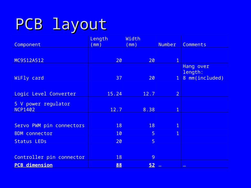
PCB layoutPCB layoutComponent Length (mm) Width (mm) Number Comments
MC9S12A512 20 20 1
WiFly card 37 20 1Hang over length:8 mm(included)
Logic Level Converter 15.24 12.7 2
5 V power regulator NCP1402 12.7 8.38 1
Servo PWM pin connectors 18 18 1
BDM connector 10 5 1
Status LEDs 20 5
Controller pin connector 18 9
PCB dimension 88 52
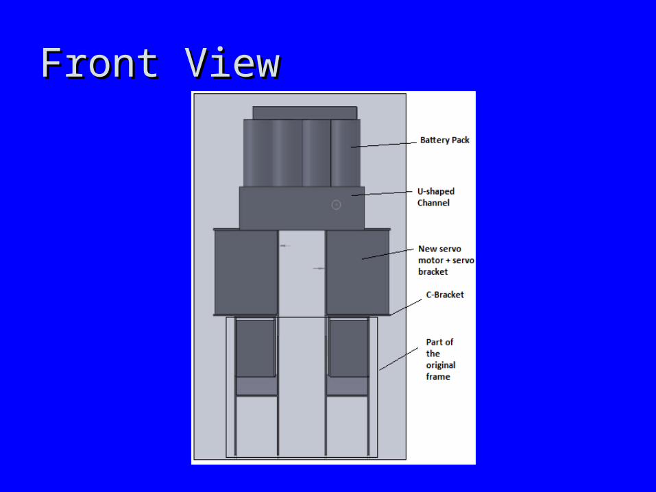
Front ViewFront View
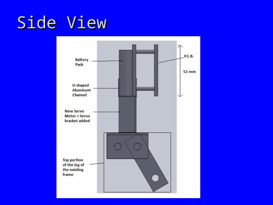
Side ViewSide View
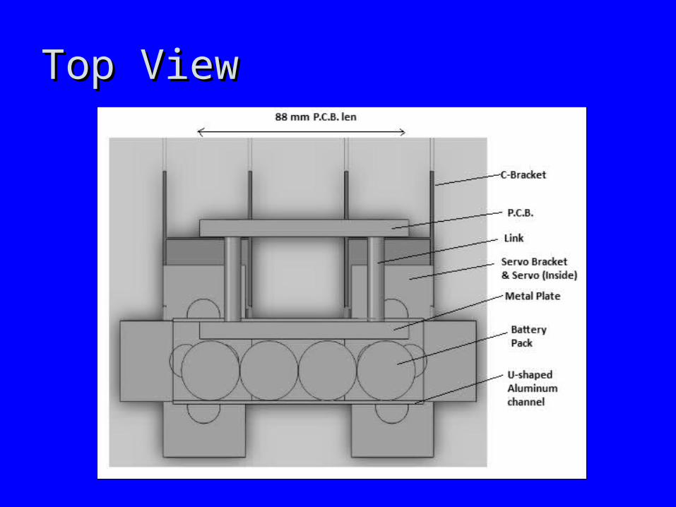
Top ViewTop View
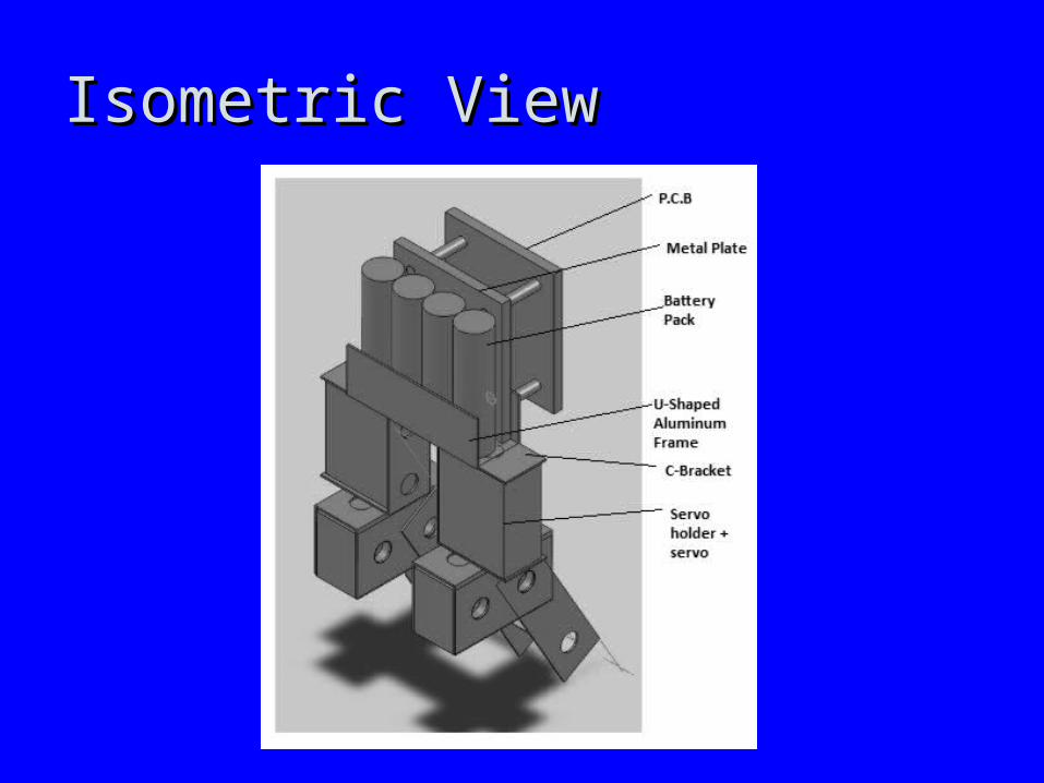
Isometric ViewIsometric View
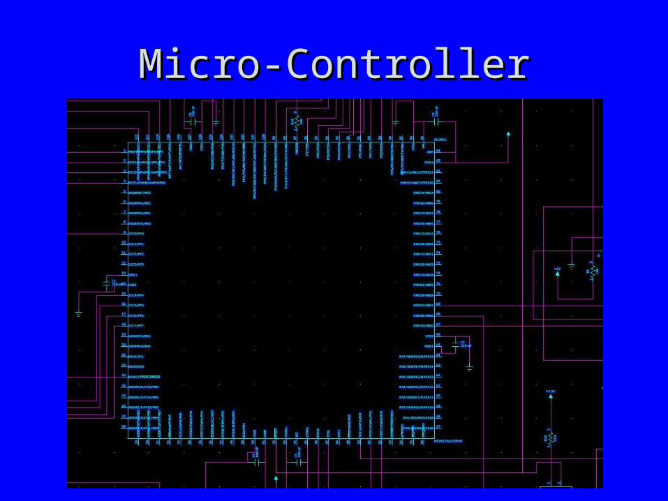
Micro-ControllerMicro-Controller
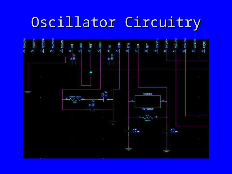
Oscillator CircuitryOscillator Circuitry
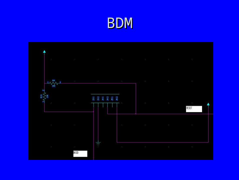
BDMBDM
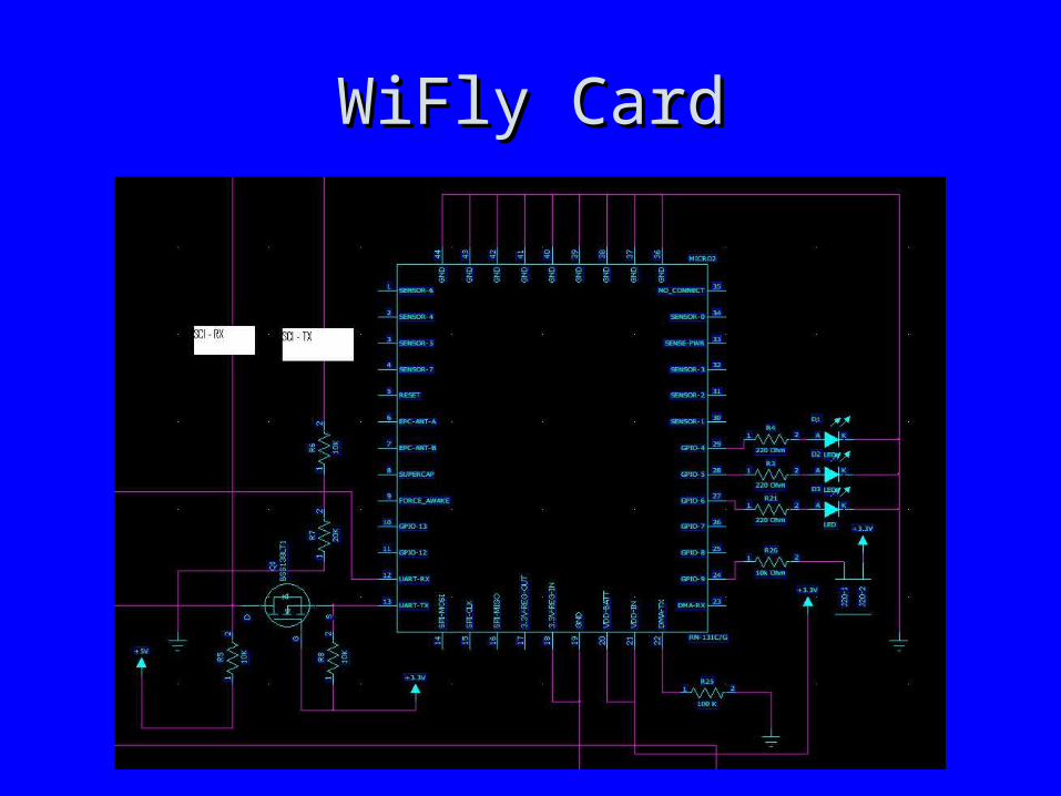
WiFly CardWiFly Card
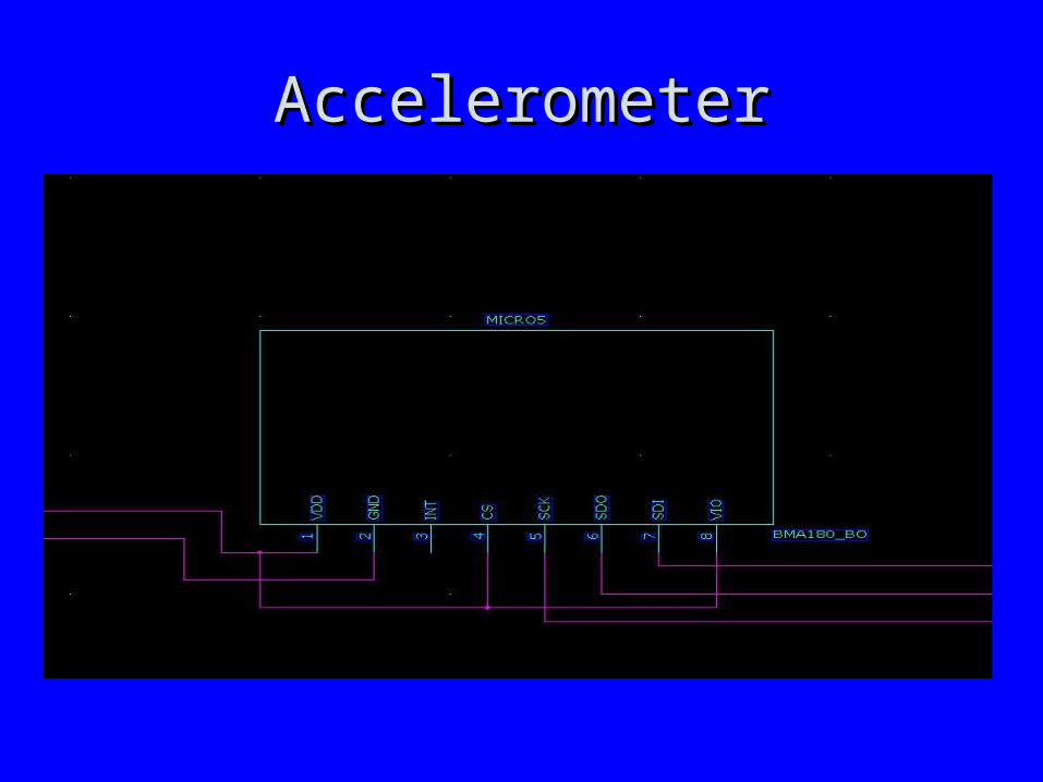
AccelerometerAccelerometer
Theory of OperationTheory of Operation• Hardware Design ObjectivesHardware Design Objectives
– Generating 8 different duty cycles, which would Generating 8 different duty cycles, which would control angular position of each servo.control angular position of each servo.
– Integrating all other components with the micro Integrating all other components with the micro controller.controller.
– Configuring the modes of the subsystems for Configuring the modes of the subsystems for each componenteach component
Theory of OperationTheory of Operation
• MicroprocessorMicroprocessor– MC9S12A512MC9S12A512– Will be run at 5 MHz using 5.0VWill be run at 5 MHz using 5.0V
• PowerPower– 12.8V LiFePO4 battery pack12.8V LiFePO4 battery pack– 5V switching regulator 5V switching regulator x 2x 2
• Pololu D24V6ALVPololu D24V6ALV• Pololu D15V70F5S3Pololu D15V70F5S3
– 3.3V linear regulator3.3V linear regulator• STMICROELECTRONICS - LD1117S33TRSTMICROELECTRONICS - LD1117S33TR
Theory of OperationTheory of Operation
• Servo motors - Hitech hc422Servo motors - Hitech hc422– Controlled with PWM on microprocessorControlled with PWM on microprocessor
• Wifi module - WiFly RN-131GWifi module - WiFly RN-131G– Ad-hoc Network, 802.11b/gAd-hoc Network, 802.11b/g
• 3-axis accelerometer - Bosch BMA1803-axis accelerometer - Bosch BMA180– Measures between 0-2GMeasures between 0-2G
• Ultrasonic range finder - Maxbotix LV-EZ2Ultrasonic range finder - Maxbotix LV-EZ2– Finds objects from 6in. to 254in.Finds objects from 6in. to 254in.
PCB ConsiderationsPCB Considerations
• SizingSizing• Three different voltages – 12.8VDC (unreg), Three different voltages – 12.8VDC (unreg),
5VDC (reg), 3.3VDC(reg).5VDC (reg), 3.3VDC(reg).• Servo motor induced power noise.Servo motor induced power noise.• Servo current draw.Servo current draw.• Signal integrity of servo motor control.Signal integrity of servo motor control.• Microcontroller (oscillator, bypass caps)Microcontroller (oscillator, bypass caps)• RF interference with WiFi radio.RF interference with WiFi radio.
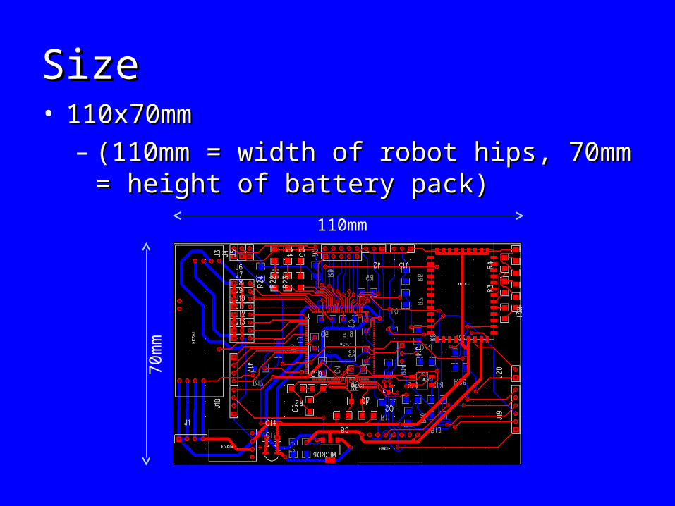
SizeSize• 110x70mm 110x70mm
– (110mm = width of robot hips, 70mm = height (110mm = width of robot hips, 70mm = height of battery pack)of battery pack)
110mm
70mm
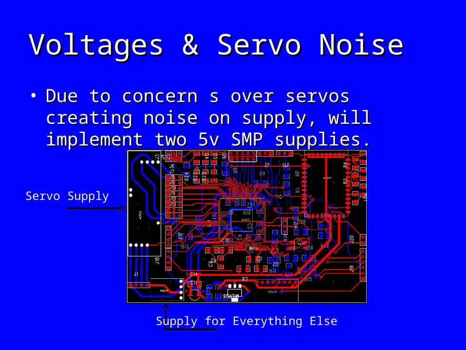
Voltages & Servo NoiseVoltages & Servo Noise
• Due to concern s over servos creating noise on Due to concern s over servos creating noise on supply, will implement two 5v SMP supplies.supply, will implement two 5v SMP supplies.
Servo Supply
Supply for Everything Else
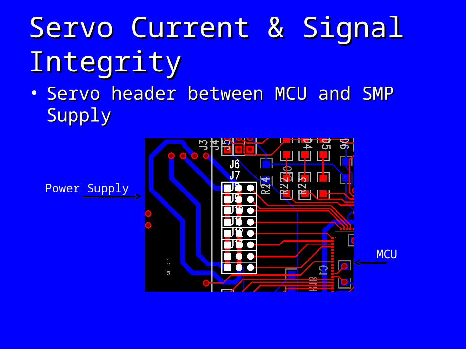
Servo Current & Signal Integrity Servo Current & Signal Integrity
• Servo header between MCU and SMP SupplyServo header between MCU and SMP Supply
Power Supply
MCU
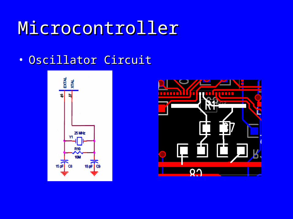
MicrocontrollerMicrocontroller
• Oscillator Circuit Oscillator Circuit
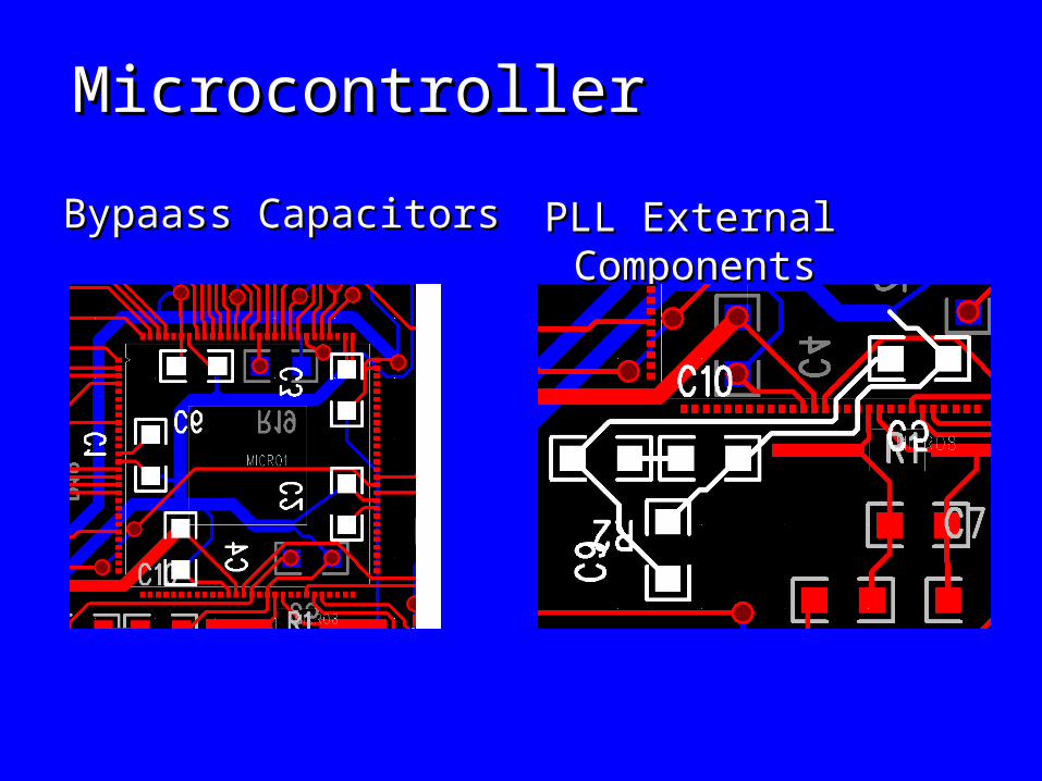
MicrocontrollerMicrocontroller
Bypaass CapacitorsBypaass Capacitors PLL External ComponentsPLL External Components
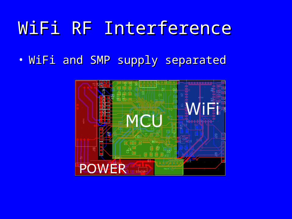
WiFi RF InterferenceWiFi RF Interference
• WiFi and SMP supply separatedWiFi and SMP supply separated
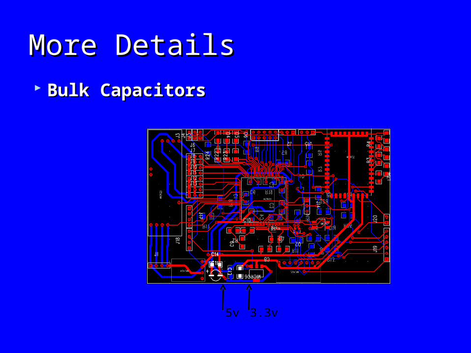
More DetailsMore Details
Bulk CapacitorsBulk Capacitors
5v 3.3v
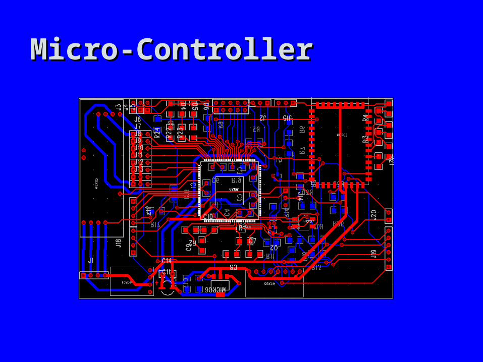
Micro-ControllerMicro-Controller
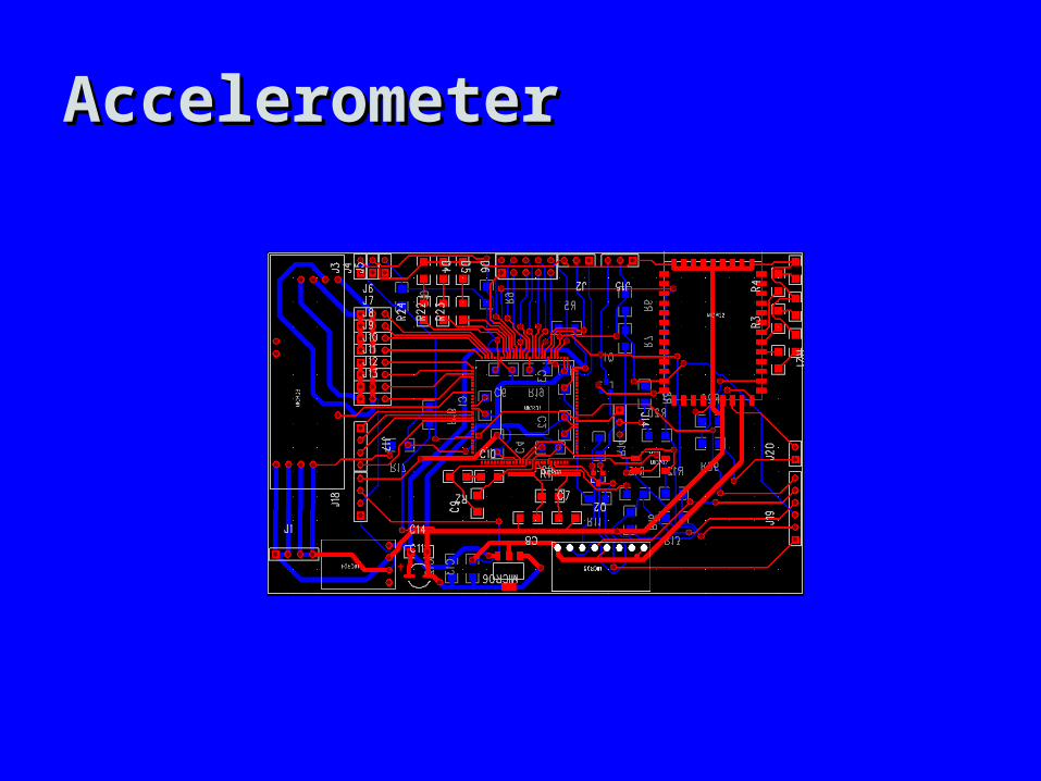
AccelerometerAccelerometer
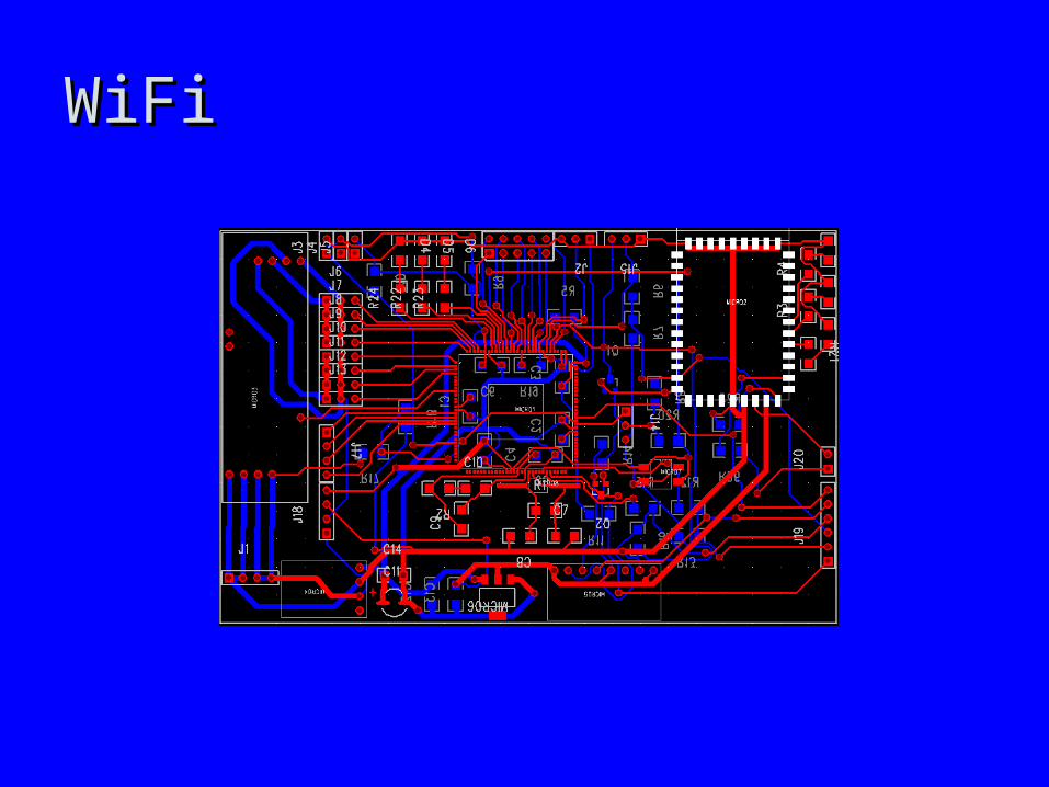
WiFiWiFi
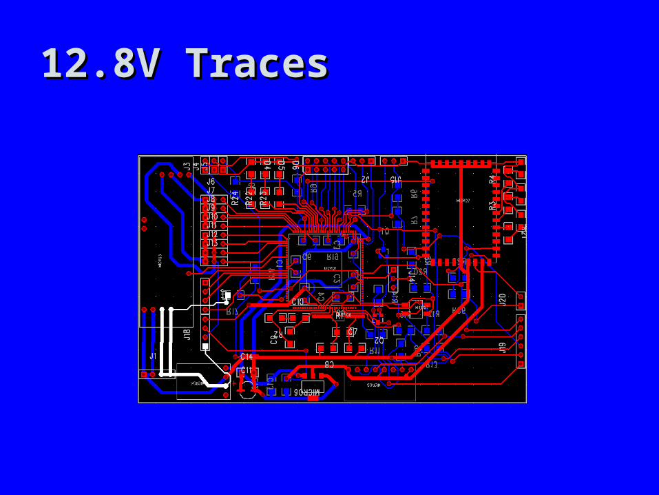
12.8V Traces12.8V Traces
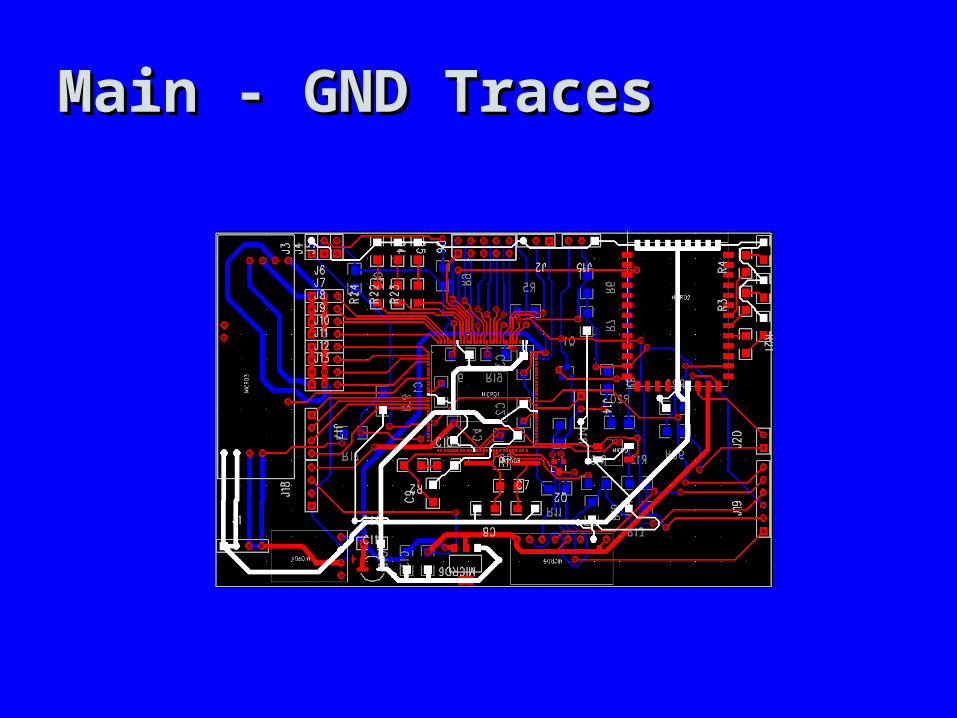
Main - GND TracesMain - GND Traces
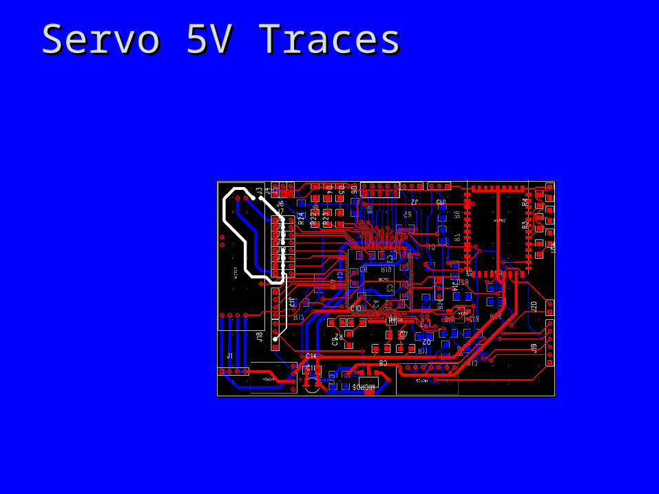
Servo 5V TracesServo 5V Traces
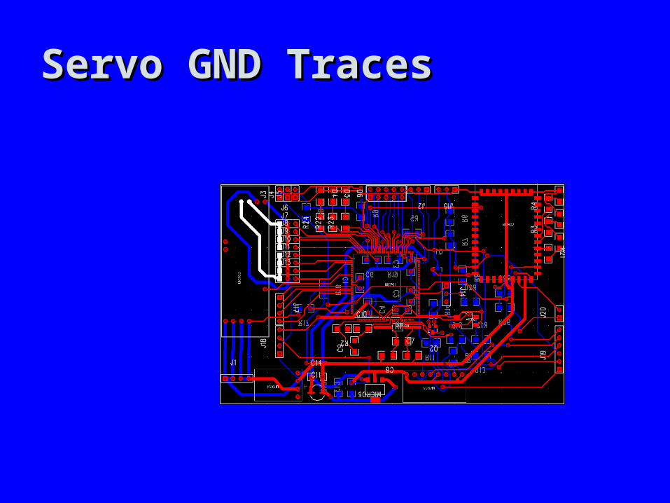
Servo GND TracesServo GND Traces
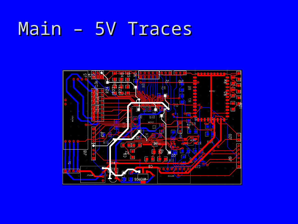
Main – 5V TracesMain – 5V Traces
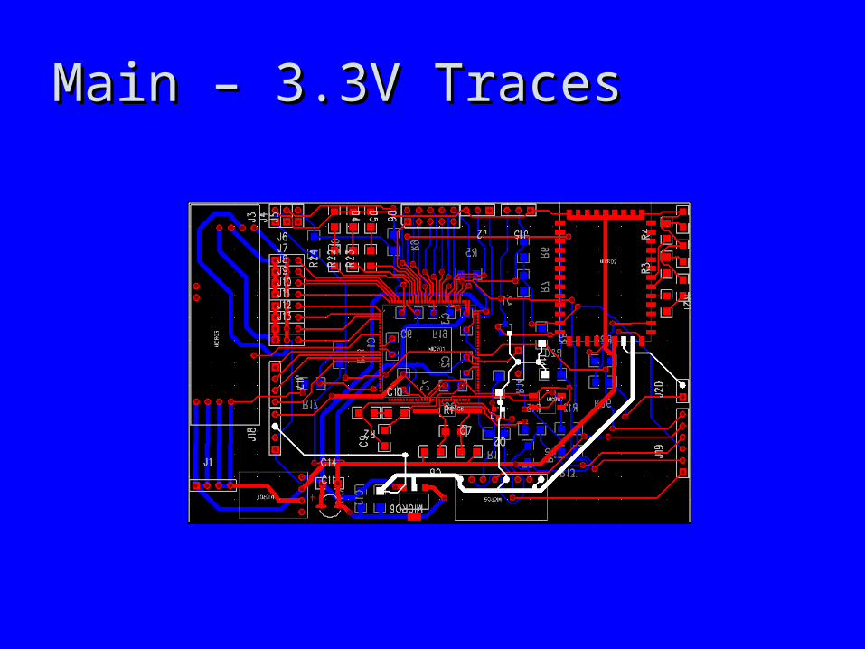
Main – 3.3V TracesMain – 3.3V Traces
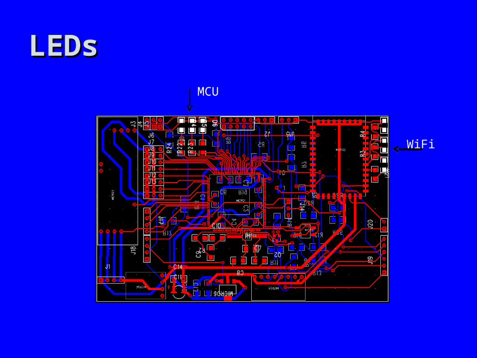
MCU
WiFi
LEDsLEDs
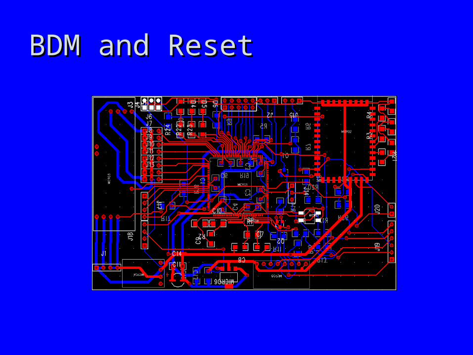
BDM and ResetBDM and Reset
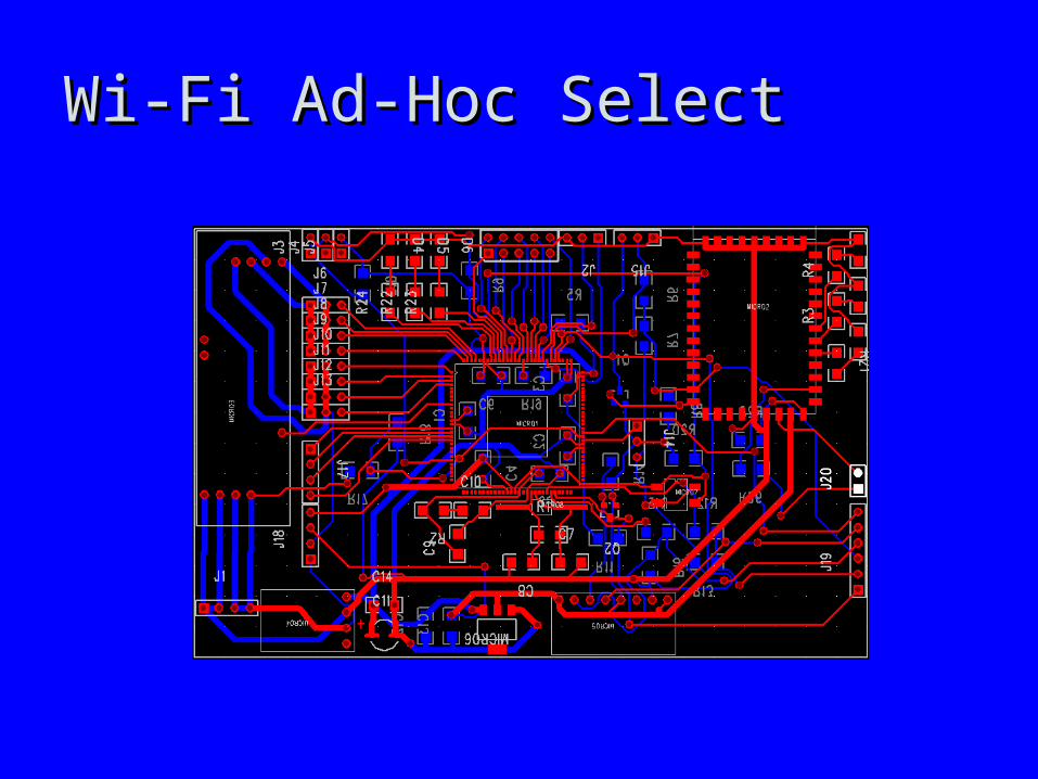
Wi-Fi Ad-Hoc SelectWi-Fi Ad-Hoc Select
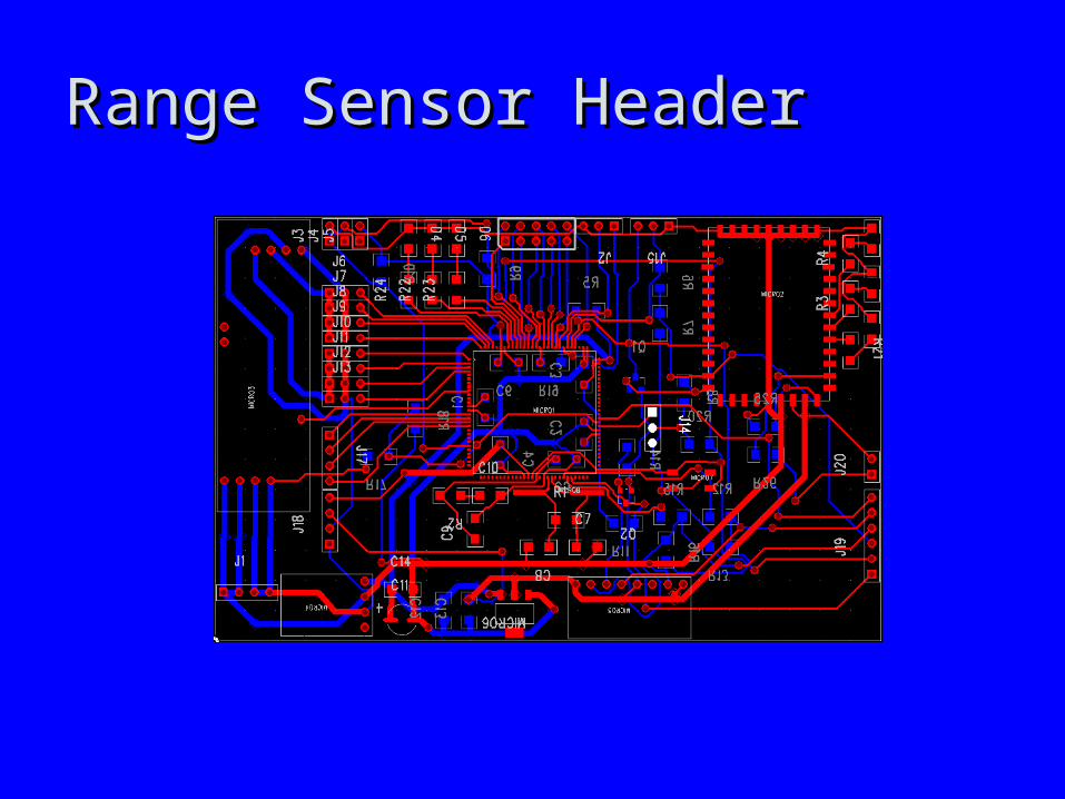
Range Sensor HeaderRange Sensor Header
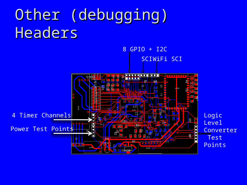
WiFi SCISCI
Logic Level Converter Test PointsPower Test Points
8 GPIO + I2C
4 Timer Channels
Other (debugging) HeadersOther (debugging) Headers
Software DesignSoftware Design
• Programming Language UsedProgramming Language Used– Microprocessor : Embedded CMicroprocessor : Embedded C– Simulation : MatlabSimulation : Matlab– GUI : C++GUI : C++
• ComplierComplier– Motorola HC/HCS12Motorola HC/HCS12
Development StatusDevelopment Status
• MatlabMatlab– Kinematic & Inverse KinematicKinematic & Inverse Kinematic– Newton’s Method for square root approximationNewton’s Method for square root approximation
• Embedded CEmbedded C– InitializationsInitializations– PWM in conjunction with TIM modulePWM in conjunction with TIM module– Look up tablesLook up tables
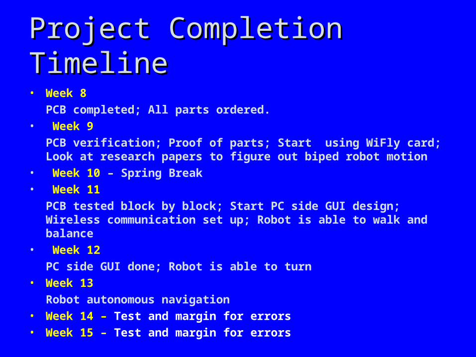
Project Completion TimelineProject Completion Timeline
• Week 8
PCB completed; All parts ordered.
• Week 9
PCB verification; Proof of parts; Start using WiFly card; Look at research papers to figure out biped robot motion
• Week 10 – Spring Break
• Week 11
PCB tested block by block; Start PC side GUI design; Wireless communication set up; Robot is able to walk and balance
• Week 12
PC side GUI done; Robot is able to turn
• Week 13
Robot autonomous navigation
• Week 14 – Test and margin for errors
• Week 15 – Test and margin for errors
Questions / DiscussionQuestions / Discussion