Embed Size (px)
Citation preview
NEER ENGI
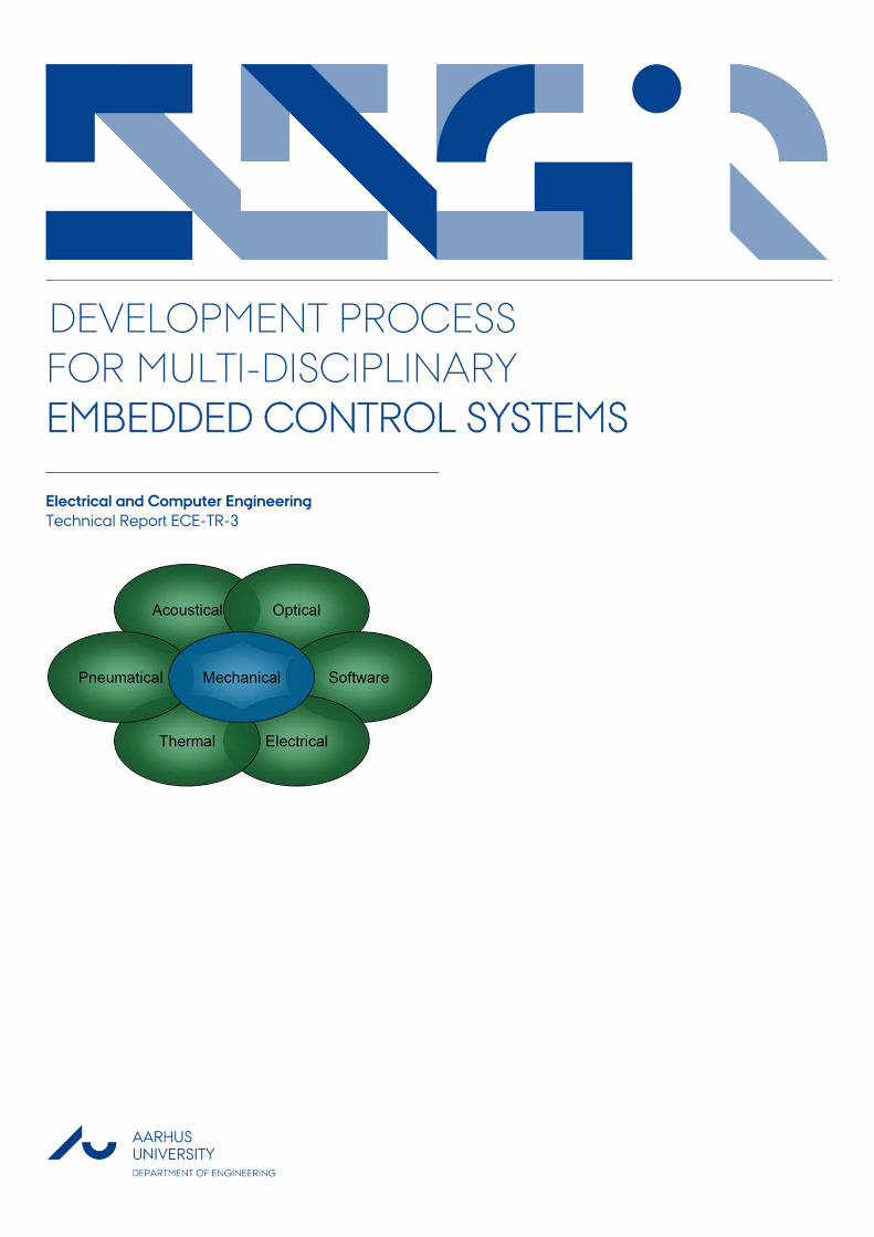
DEVELOPMENT PROCESS FOR MULTI-DISCIPLINARY EMBEDDED CONTROL SYSTEMS
Electrical and Computer Engineering Technical Report ECE-TR-3
DATA SHEET Title: Development Process for Multi-Disciplinary Embedded Control Systems Subtitle: Electrical and Computer Engineering Series title and no.: Technical report ECE-TR-3 Author: Sune Wolff, Department of Engineering – Electrical and Computer Engineering, Aarhus University Internet version: The report is available in electronic format (pdf) at the Department of Engineering website http://www.eng.au.dk. Publisher: Aarhus University© URL: http://www.eng.au.dk Year of publication: 2012 Pages: 46 Editing completed: August 2011 Abstract: This report contains the progress report for the qualification exam for Industrial PhD student Sune Wolff. Initial work on describing a development process for multi-disciplinary systems using collaborative modelling and co-simulation is described. Keywords: Development process, multi-disciplinary, embedded systems Acknowledgement: This work has been conducted in cooperation between Terma, Engineering College of Aarhus and Department of Computer Science, Aarhus University Supervisor: Peter Gorm Larsen Financial support: Danish Agency for Science Technology and Innovation Please cite as: Sune Wolff, 2012. Development Process for Multi-Disciplinary Embedded Control Systems. Department of Engineering, Aarhus University. Denmark. 46 pp. Technical Report ECE-TR-3 Cover image: Created by Sune Wolff ISSN: 2245-2087 Reproduction permitted provided the source is explicitly acknowledged
DEVELOPMENT PROCESS FOR MULTI-DISCIPLINARY
EMBEDDED CONTROL SYSTEMS
Sune Wolff — Aarhus University, Department of Engineering
Abstract This report contains the progress report for the qualification exam for Industrial PhD student Sune Wolff. Initial work on describing a development process for multi-disciplinary systems using collaborative modelling and co-simulation is described.
Contents
1 Introduction 11.1 Structure of the Progress Report . . . . . . . . . . . . . . . . . . . . . 1
2 Background 32.1 Embedded Systems Design Challenges . . . . . . . . . . . . . . . . . . 3
2.1.1 Academic Research Projects . . . . . . . . . . . . . . . . . . . 52.2 Model-Driven Development . . . . . . . . . . . . . . . . . . . . . . . 6
2.2.1 Discrete-Event Modelling . . . . . . . . . . . . . . . . . . . . 62.2.2 Continuous-Time Modelling . . . . . . . . . . . . . . . . . . . 72.2.3 Multi-Domain Modelling . . . . . . . . . . . . . . . . . . . . . 8
2.3 Summary . . . . . . . . . . . . . . . . . . . . . . . . . . . . . . . . . 10
3 Development Process for Discrete-Event Systems 113.1 VDM-RT Model Development Methodology . . . . . . . . . . . . . . 11
3.1.1 An Incremental Approach to Model Construction . . . . . . . . 123.2 Using Formal Methods in Agile System Development . . . . . . . . . . 14
3.2.1 Are Formal Methods Ready for Agility? . . . . . . . . . . . . . 143.2.2 Adding Formal Methods to Scrum . . . . . . . . . . . . . . . . 153.2.3 Concluding Remarks . . . . . . . . . . . . . . . . . . . . . . . 17
3.3 Industrial Case - VDM Model Development . . . . . . . . . . . . . . . 183.3.1 Case Description . . . . . . . . . . . . . . . . . . . . . . . . . 183.3.2 Discussion of Results . . . . . . . . . . . . . . . . . . . . . . . 19
3.4 Summary of Discrete-Event Work . . . . . . . . . . . . . . . . . . . . 21
4 Development Process for Multi-Disciplinary Systems 234.1 Collaborative Modelling and Co-simulation . . . . . . . . . . . . . . . 23
4.1.1 Basic Co-simulation in 20-sim and VDM . . . . . . . . . . . . 254.2 Tools . . . . . . . . . . . . . . . . . . . . . . . . . . . . . . . . . . . . 274.3 Casework . . . . . . . . . . . . . . . . . . . . . . . . . . . . . . . . . 284.4 Summary of Multi-Disciplinary Work . . . . . . . . . . . . . . . . . . 28
i
ii CONTENTS
5 Summary and Future Work 315.1 Summary of Work . . . . . . . . . . . . . . . . . . . . . . . . . . . . . 31
5.1.1 Discrete-event Modelling . . . . . . . . . . . . . . . . . . . . . 315.1.2 Multi-domain Modelling . . . . . . . . . . . . . . . . . . . . . 32
5.2 Future Work . . . . . . . . . . . . . . . . . . . . . . . . . . . . . . . . 325.2.1 Methodology . . . . . . . . . . . . . . . . . . . . . . . . . . . 325.2.2 Tools . . . . . . . . . . . . . . . . . . . . . . . . . . . . . . . 335.2.3 Case work . . . . . . . . . . . . . . . . . . . . . . . . . . . . . 33
5.3 Concluding Remarks . . . . . . . . . . . . . . . . . . . . . . . . . . . 34
Bibliography 35
A My Publications 43A.1 Methodology . . . . . . . . . . . . . . . . . . . . . . . . . . . . . . . 43A.2 Cases . . . . . . . . . . . . . . . . . . . . . . . . . . . . . . . . . . . 43A.3 Overture . . . . . . . . . . . . . . . . . . . . . . . . . . . . . . . . . . 43A.4 Misc . . . . . . . . . . . . . . . . . . . . . . . . . . . . . . . . . . . . 43
B Courses Completed 45
Chapter 1
Introduction
This progress report describes the scientific work, which has been carried out as part ofthe first year and a half of my Industrial Ph.D. studies. The goal of the report is to givean overview of the work and give directions for future work.
The main focus of my work has been on combined simulation (called co-simulation)of models from different domains using different models of computation, in order to givea holistic description of an embedded system. The intended outcome of the PhD projectis a methodology describing the work flow when utilising co-simulation in embeddedsystems development.
So far, the work has resulted in eight papers which have been submitted/published atinternational conferences or journals.
1.1 Structure of the Progress Report
In Chapter 2, a general introduction to the challenges in developing embedded systemsis given based on [51]. Chapter 3 introduces different single-domain methodologiesuseful for developing software systems using abstract system level formal models. Thischapter is based on the work presented in [31, 48, 32, 49, 39], and covers methods fordeveloping models in the formal specification language VDM, as well as methods forcombining agile development methodologies with the use of formal methods. Followingthis introduction, a case study is described where several subsystems of a self-defensesystem for fighter aircraft were modelled in VDM++, as presented in [50]. In Chapter 4initial results of a multi-domain methodology making use of co-simulation is described,based on [17]. Finally, in Chapter 5 summary of work as well as future work, andcurrent work not yet published, is outlined. In Appendix A my publications are listed,and Appendix B gives an overview of the courses I have completed in the first half ofmy Ph.D studies.
1

Chapter 2
Background
This chapter will introduce the reader to the background of the project and reasons whythe work is needed. Various model-driven development techniques, both formal and in-formal languages and tools, will also be introduced in this chapter which is based on [51].The systems of interest are multi-disciplinary embedded control systems, which are alsocalled hybrid or cyber-physical systems – these names will be used interchangeably inthis report.
2.1 Embedded Systems Design Challenges
The development of hybrid systems consisting of software, electronics and mechanicalcomponents which are operating in a physical world is a very complex challenge [23,24]. These challenges arise from the need to develop complex, software-rich productsthat take the constraints of the physical world into account. The task is made even morechallenging due to the fact that these types of systems often are developed out of phase –initially the mechanical parts are designed, followed by electronics and finally softwareis designed. Any problems discovered late in the development process, can really onlybe corrected in the software without causing huge delays to the complete project dueto longer iterative cycles in electronics and mechanical development. These very latechanges often increase the complexity of the software and the risk of introducing newbugs. Hence, an otherwise well thought-out software design can be compromised. Inorder to avoid situations like this, early feedback at a systems level is invaluable.
In order to develop hybrid systems, engineers from different backgrounds and withdiverse fields of expertise are involved, making communication much harder than inmono-disciplinary projects. It is close to impossible for each individual engineer toforesee all the cross-discipline consequences of a given design decision.
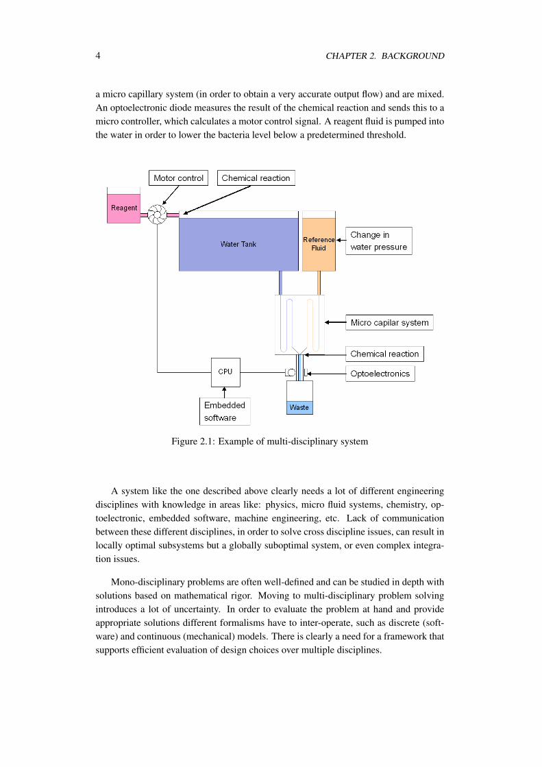
Consider the system in Figure 2.1 describing a system controlling the level of bac-teria in a water reservoir. A sample of the water and a reference fluid is passed through
3
4 CHAPTER 2. BACKGROUND
a micro capillary system (in order to obtain a very accurate output flow) and are mixed.An optoelectronic diode measures the result of the chemical reaction and sends this to amicro controller, which calculates a motor control signal. A reagent fluid is pumped intothe water in order to lower the bacteria level below a predetermined threshold.
Figure 2.1: Example of multi-disciplinary system
A system like the one described above clearly needs a lot of different engineeringdisciplines with knowledge in areas like: physics, micro fluid systems, chemistry, op-toelectronic, embedded software, machine engineering, etc. Lack of communicationbetween these different disciplines, in order to solve cross discipline issues, can result inlocally optimal subsystems but a globally suboptimal system, or even complex integra-tion issues.
Mono-disciplinary problems are often well-defined and can be studied in depth withsolutions based on mathematical rigor. Moving to multi-disciplinary problem solvingintroduces a lot of uncertainty. In order to evaluate the problem at hand and provideappropriate solutions different formalisms have to inter-operate, such as discrete (soft-ware) and continuous (mechanical) models. There is clearly a need for a framework thatsupports efficient evaluation of design choices over multiple disciplines.
2.1. EMBEDDED SYSTEMS DESIGN CHALLENGES 5
2.1.1 Academic Research Projects
In the academic world, hybrid systems have been considered for more than a decadestarting from a fuzzy logic perspective [20] to an automata perspective [22]. Since then,many academic research projects have attempted to tackle the challenges for developingsuch multi-disciplinary systems in predictable fashions. These include:
• AVACS investigates automatic verification and analysis of complex systems inparticular hybrid systems using model checking.
• CREDO focuses on the development and application of an integrated suite of toolsfor compositional modeling, testing, and validation of software for evolving net-works of dynamically reconfigurable components.
• DEPLOY is a major European FP7/IP addressing the industry deployment of for-mal methods for fault tolerant (discrete event) computing systems.
• INTERESTED focuses on creating a reference and open interoperable embeddedsystems tool-chain. The project’s main focus is on discrete event tools for graphi-cal overview and code generation, and not on co-simulation.
• MEDEIA aims to bridge the gap between engineering disciplines in the discreteengineering domain, by using containers that contain design models from vari-ous disciplines which can be seamlessly interconnected. Like the INTERESTED,MEDEIA aims to connect tools in the discrete event domain.
• PREDATOR aims to advance the state of the art in the development of safety-critical embedded systems focusing on timing aspects. systems.
• QUASIMODO aims to develop techniques and tools for model-driven design,analysis, testing and code-generation for embedded systems where ensuring quan-titative bounds on resource consumption is a central problem. It focuses on formalnotations for timed, probabilistic and hybrid systems that can be subjected to ex-haustive state space analysis techniques such as model checking.
• SPEEDS focus on tool-supported collaborative modeling for embedded systemsdesign.
• VERTIGO aims to develop a systematic methodology to enhance modeling, inte-gration and verification of architectures targeting embedded systems. It will use aco-simulation strategy that allows the correctness of the interaction between HWand SW to be assessed by simulation and assertion checking.
In 2007 the major stakeholders for embedded systems in Europe have jointly startedthe organization ARTEMIS (Advanced Research & Technology in Embedded Intelli-gence and System). They have defined a Strategic Research Agenda (SRA) to focus on
6 CHAPTER 2. BACKGROUND
the main challenges for the future. In this SRA it is explicitly stated that there is a needfor multidisciplinary, multi-objective, systems design techniques that will yield appro-priate price/performance for acceptable power and with manageable temporal behavior.
One of the main concerns of my Industrial Ph.D. project is to bridge the gab betweenindustry and academia by ensuring that the project outcome solves actual issues seen inindustry. In addition, it is of great importance that the final methodology described fitsinto existing development methods used in industry, and hence can be applied with asfew alterations as possible.
2.2 Model-Driven Development
Model driven development can address some of these challenges. Normally, the dif-ferent types of engineers involved in the development of a hybrid system make use ofdomain specific tools in order to create models of the individual parts of the system.This enables the individual disciplines to optimize one specific part of the system. Bycreating abstract high-level multi-disciplinary models of the entire hybrid system andthe ability to run a co-simulation of these, system engineers will be able to reason aboutsystem-level properties of the control system across multiple disciplines. This will en-sure early feedback on system properties, as well as ease communication across differentdisciplines, since the impact of a given design decision can be made visible to the entireteam.
A major challenge in model-driven development of hybrid systems, lies in the com-bination of the models used by the different disciplines involved in the development ofthe system. As long as the models lies within the same domain, this challenge is of lim-ited complexity. When combining models from different domains like continuous-timeand discrete-event models, the challenge is significant, and as will be argued this has notyet been done in a satisfying manner.
2.2.1 Discrete-Event Modelling
Software engineers can make use of discrete-event models when specifying the logic ofthe controller of an embedded system. Formal methods can be used to describe thesemodels, where a mathematically based notation enables the engineer to rigorously de-scribe and analyze the properties of the controller [47]. The motivation of using thesemodels is to precisely describe the desired properties of the systems, while applyinga higher level of abstraction to less important parts of the system. For example, devicedrivers and hardware components can be excluded from the model, enabling the softwareengineer to focus on the algorithmic challenges of the controller.
Several different discrete-event notations are used in industry and academia. Withouta doubt, one of the most commonly used technique in industry is the graphical notation”Unified Modeling Language” (UML) created by the Object Management Group. UMLenables engineers to create several different views of the software under design. For ex-
2.2. MODEL-DRIVEN DEVELOPMENT 7
ample, requirement specification using use-case diagrams, static architecture using classdiagrams and dynamic behavior using sequence diagrams. Industrial strength tools likeIBM Rational Rhapsody enables the software engineer to code generate full C/C++ andJava code from a complete suite of UML diagrams, in order to uncover defects earlierin the product life cycle. An extension to UML called SysML [42] (System ModellingLanguage) has been created where system blocks can be defined without having to de-termine if it is a hardware or software entity.
In object-oriented formal languages, like VDM [16] (Vienna Development Method),the desired functionality of the controller can be described at the desired level of ab-straction. This is a major advantage, since the model can describe the current problem athand, and disregard all other parts of the system. Since VDM is used extensively in theproject, it will be described in more details here.
VDM is a collection of techniques to formally specify and develop software. VDMoriginates from IBM’s Laboratories in Vienna in the 1970s. The very first languagesupported by the VDM method was called Vienna Definition Language (VDL), whichevolved into the meta-language Meta-IV [21, 4] and later into the specification languageVDM-SL [40]. Over the years, extensions have been defined to model object-orientation(VDM++ [16]) and distributed real-time systems (VDM-RT [35, 45]). Two alternativetools exists; the commercial tool VDMTools [18] and the open source initiative Over-ture [29].
Data in VDM models can be described using simple abstract data types such asnatural numbers, booleans and characters, as well as product and unions types and col-lection types such as sets, sequences and mappings. VDM has both a mathematical andan ASCII based syntax, where the latter is used in this report. The system state canbe described using state in VDM-SL and instance variables in VDM++ andVDM-RT, the value of which can be restricted by invariants. To modify the state of thesystem, operations can be defined either explicitly by imperative statements, or implic-itly by pre- and post-conditions. Functions which cannot use or modify the state can bedefined in a similar fashion.
VDM has been used in several successful industrial applications e.g. [30] – exam-ples of two recent applications in the Japanese industry is the TradeOne system devel-oped by CSK systems for the Japanese stock exchange [16] and the FeliCa contactlesschip firmware [28, 27]. Most of these applications have the common goal of providingrapid feedback on requirements and design early in the development cycle, by utilisingexecutable models and doing lightweight formal analysis of these.
2.2.2 Continuous-Time Modelling
In classical physics, aspects like movement, acceleration and force are described us-ing differential equations. Naturally, models of the environment in which an embed-ded system is operating is best described using differential equations as well. Whereascontinuous-time models excel at describing physical movement, hydraulics and pneu-
8 CHAPTER 2. BACKGROUND
matics, they generally lack the possibility to apply the correct level of abstraction to thediscrete-event controller.
In industry Matlab/Simulink [34] created by MathWorks is possibly one of the mostwidely used tool for creating continuous-time models. Matlab is a high-level languageand interactive environment which perform computationally intensive tasks very fastcompared to traditional programming languages. Simulink is an environment for multi-domain simulation and Model-Based Design for dynamic and embedded systems. Itprovides an interactive graphical environment and a customizable set of block librarieswhich lets the user design, simulate, implement, and test a variety of time-varying sys-tems, including communications, controls, signal processing, video processing, and im-age processing.
20-sim [8], formerly CAMAS [7], is a tool for modelling and simulation of dynamicsystems including electronics, mechanical and hydraulic systems. All models are basedon Bond Graphs [26] which is a non-causal technology, where the underlying equationsare specified as equalities. Hence variables do not initially need to be specified as inputsor outputs. In addition, the interface between Bond Graph elements is port-based whereeach port has two variables that are computed in opposite directions, for example voltageand current in the electrical domain. 20-sim also supports graphical representation ofthe mathematical relations between signals in the form of block diagrams and iconicdiagrams (building blocks of physical systems like masses and springs) as more userfriendly notations. Combination of notations is also possible, since Bond Graphs providea common basis. It is possible to create sub-models of multiple components or evenmultiple sub-models allowing for a hierarchical model structure.
There are many other continuous-time modelling and simulation tools, including:
• Modelica – non-causal multi-domain modelling language [19]
• Scilab – open source version of MATLAB [53]
• Ptolemy – multi-domain modelling tool [10, 12, 13]
• SPICE – modelling of electrical systems [36]
A comparative survey of some of these tools have been carried out, described inSection 4.2.
2.2.3 Multi-Domain Modelling
Whereas the individual technologies and tools described above excel at creating modelsin their specific domain, few (if any) are suitable for modeling systems operating on bothdiscrete-events and in continuous-time. The Stateflow application from MathWorks ex-tends Simulink by allowing the use of language elements to describe complex logic. It istightly integrated with Matlab and Simulink, and provides an environment for designingembedded hybrid systems. Matlab is a very efficient tool for algorithm development and
2.2. MODEL-DRIVEN DEVELOPMENT 9
large calculations, but lacks the possibility of using object-oriented architecture. Thetool chain is also limited in the inability to apply a higher level of abstraction to parts ofthe system not currently in focus.
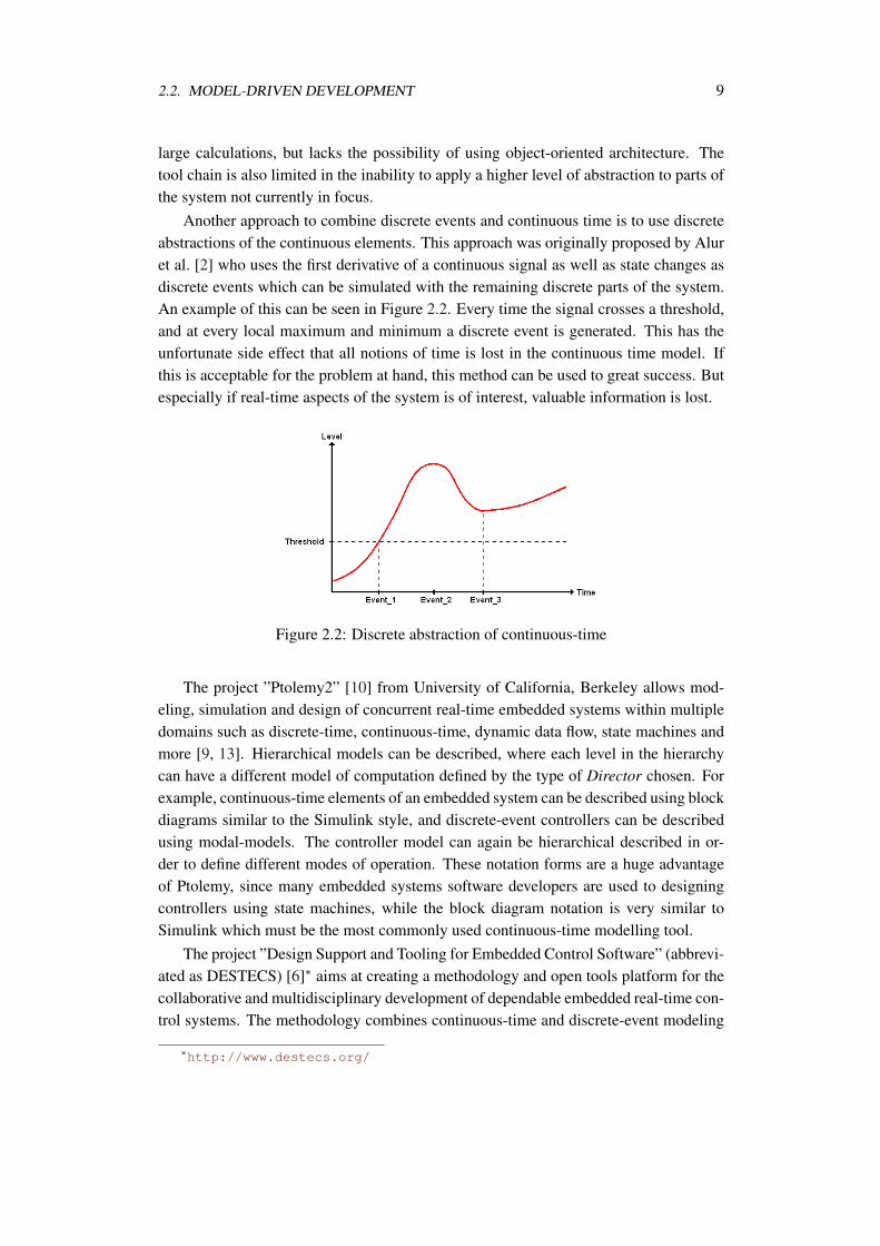
Another approach to combine discrete events and continuous time is to use discreteabstractions of the continuous elements. This approach was originally proposed by Aluret al. [2] who uses the first derivative of a continuous signal as well as state changes asdiscrete events which can be simulated with the remaining discrete parts of the system.An example of this can be seen in Figure 2.2. Every time the signal crosses a threshold,and at every local maximum and minimum a discrete event is generated. This has theunfortunate side effect that all notions of time is lost in the continuous time model. Ifthis is acceptable for the problem at hand, this method can be used to great success. Butespecially if real-time aspects of the system is of interest, valuable information is lost.
Figure 2.2: Discrete abstraction of continuous-time
The project ”Ptolemy2” [10] from University of California, Berkeley allows mod-eling, simulation and design of concurrent real-time embedded systems within multipledomains such as discrete-time, continuous-time, dynamic data flow, state machines andmore [9, 13]. Hierarchical models can be described, where each level in the hierarchycan have a different model of computation defined by the type of Director chosen. Forexample, continuous-time elements of an embedded system can be described using blockdiagrams similar to the Simulink style, and discrete-event controllers can be describedusing modal-models. The controller model can again be hierarchical described in or-der to define different modes of operation. These notation forms are a huge advantageof Ptolemy, since many embedded systems software developers are used to designingcontrollers using state machines, while the block diagram notation is very similar toSimulink which must be the most commonly used continuous-time modelling tool.
The project ”Design Support and Tooling for Embedded Control Software” (abbrevi-ated as DESTECS) [6]∗ aims at creating a methodology and open tools platform for thecollaborative and multidisciplinary development of dependable embedded real-time con-trol systems. The methodology combines continuous-time and discrete-event modeling
∗http://www.destecs.org/
10 CHAPTER 2. BACKGROUND
via co-simulation, allowing explicit modeling of faults and fault-tolerance mechanismsfrom the outset. Continuous-time models are expressed using bond graphs supported bythe 20-sim tool while discrete-event controllers are modeled using VDM supported bythe Overture tools. This project holds great promise both regarding tools and methodol-ogy, and will be followed closely throughout this project.
2.3 Summary
Designing multi-disciplinary systems consisting of software, electronics and mechani-cal components is a highly complex affair, and existing mono-disciplinary developmentmethods cannot be applied directly to these types of systems. Even though a lot of aca-demic projects has been carried out in this area of research, few - if any - has gainedacceptance in industry.
The aim of the project ”Development Process for Multi-Disciplinary EmbeddedControl Systems” is to describe a model-driven development methodology, which canbe used as a golden reference when creating system-level models in multi-disciplinaryprojects. It is of great importance that the method fits into existing classic developmentprocesses, as well as support dialog across disciplines. The methodology will be testedon case studies of safety-critical hybrid systems. It is imperative that the developedmethod can be widely accepted by engineers with different fields of expertise such aselectronics, mechanics and software.
Chapter 3
Development Process forDiscrete-Event Systems
As a natural first step towards describing a methodology for multi-domain systems, sig-nificant work has been put into describing a development process for discrete-event sys-tems. A development methodology for VDM-RT models is describes in [31] and withan alternative case study in [39].
Agile methods have gained acceptance in the software industry as a means to in-corporate the customer more in the development process by releasing several workingversion of the system in an iterative manner. In [32] the agile manifesto and the 12 ag-ile principles are analysed in order to investigate if agile principles are compatible withformal modelling techniques. In [49] a concrete example of adding the use of formalmethods to the agile development process Scrum is described.
In [50] an industrial case is described where a VDM model was created in order toinvestigate the impact of a suggested update to the interface between two subsystems ofa self-defense system for fighter aircraft. This case serves as an example of using thedevelopment processes described above.
3.1 VDM-RT Model Development Methodology
The development of distributed embedded systems presents a considerable challenge.Designs for such systems are typically complex because of the need to address timing,concurrency and distribution aspects in addition to functionality. This complexity hin-ders the validation of designs and the exploration of alternatives. As a consequencedesign errors can prove expensive to correct if not detected early. The problem is madeworse by the characteristics of the embedded systems business, in which sound designdecisions have to be made early and rapidly in order to achieve a short time to market.
11
12 CHAPTER 3. DEVELOPMENT PROCESS FOR DISCRETE-EVENT SYSTEMS
Formal models have a potentially valuable role to play in managing the complex-ity of embedded systems design. Rapid feedback from the machine-assisted analysisof such models has the potential to reduce the risk of expensive re-working as a conse-quence of the late detection of defects. However, models that incorporate the descriptionof functionality alongside timing behaviour and distribution across shared computingresources are themselves potentially complex. Moving too rapidly to such a complexmodel can increase modelling and design costs in the long run.
While there are many formal notations for the representation of distributed and real-time systems, guides to practical methods for model construction and analysis are es-sential if these approaches are to be deployed successfully in industrial settings. Suchmethods should be incremental, allowing the staged introduction of detail. They shouldalso allow the decomposition of the validation task by permitting tool- supported analy-sis of the models produced at each stage. They should use tools that maximise the valuegained in return for sustainable levels of investment in training as well as in creating andanalysing formal models.
A pragmatic and tool-supported method for the stepwise development of modelsof distributed embedded systems is summarised in the following. At each step in ourmethod, we develop a model that considers an additional aspect of the design problem,such as distribution or concurrency. Our approach uses and extends the Vienna Develop-ment Method (VDM) [4, 25, 15, 16] and its tools: VDMTools [18] and Overture [37]). Acomprehensive description of the method of model derivation and forms a contributionto the methodological guidelines accompanying VDMTools [11] is provided.
3.1.1 An Incremental Approach to Model Construction
The goal is to describe a method for developing formal models of distributed real-timesystems that is incremental and allows tool-supported validation of the models producedat each stage. We propose a stepwise approach [11] which exploits the capabilitiesof each of the VDM modelling language extensions described in Section 2.2.1. Ourapproach aims to assist the management of complexity by enabling the developer toconsider a different facet of the modelled system at each stage. The steps themselves areas follows:
1. System Boundary Definition
2. Sequential Design Modelling
3. Concurrent Design Modelling
4. Distributed Real-time Design Modelling
In the design of embedded systems, a key early decision is the drawing of the bound-ary between the environment, which consists of elements that can not be controlled bythe designer, and the controller that is to be developed. In particular, this allows the
3.1. VDM-RT MODEL DEVELOPMENT METHODOLOGY 13
developer to state assumptions about environment behaviour and the guarantees that de-scribe the correct operation of the controller in a valid environment. The first stageof our method involves making the system boundary, assumptions and guarantees ex-plicit. Such an explicit abstract description can be given informally or using both formaland informal elements side by side. It may also be given purely formally, often usingdomain-specific notations, though we will not illustrate that aspect here.
Based on this abstract description, an object-oriented architecture is introduced, cre-ating a sequential model with structure expressed using the features of VDM++. Con-sideration of the synchronisation of concurrent activities is deferred in order to focuson functional aspects. In the next stage, this sequential model is extended to encom-pass concurrency and thread synchronisation (still using the VDM++ language, whichincludes concurrency modelling features). Subsequently, the concurrent design modelmay be extended with real-time information using the VDM-RT extensions. Finally, dis-tribution over a distributed embedded architecture can be described, using the VDM-RTextensions. At this stage it may prove necessary to revisit the concurrent design model,since design decisions made at that stage may prove to be infeasible when real-time in-formation is added to the model (for instance, the model may not be able to meet itsdeadlines). From the concurrent and distributed real-time VDM++ design model an im-plementation may subsequently be developed. Testing of the final implementation andthe various design-oriented models may be able to exploit the more abstract models as atest oracle. Note that the approach suggested here enables continuous validation of themodels if these are written in executable subsets of the different VDM dialects.
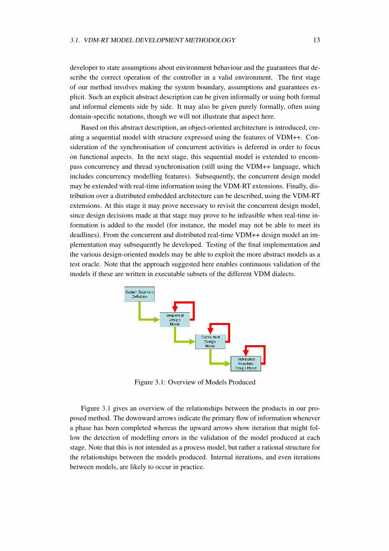
Figure 3.1: Overview of Models Produced
Figure 3.1 gives an overview of the relationships between the products in our pro-posed method. The downward arrows indicate the primary flow of information whenevera phase has been completed whereas the upward arrows show iteration that might fol-low the detection of modelling errors in the validation of the model produced at eachstage. Note that this is not intended as a process model, but rather a rational structure forthe relationships between the models produced. Internal iterations, and even iterationsbetween models, are likely to occur in practice.
14 CHAPTER 3. DEVELOPMENT PROCESS FOR DISCRETE-EVENT SYSTEMS
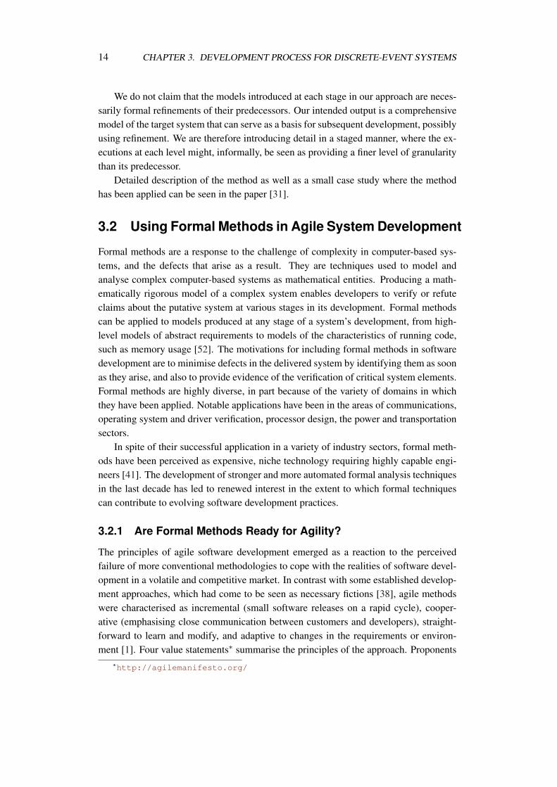
We do not claim that the models introduced at each stage in our approach are neces-sarily formal refinements of their predecessors. Our intended output is a comprehensivemodel of the target system that can serve as a basis for subsequent development, possiblyusing refinement. We are therefore introducing detail in a staged manner, where the ex-ecutions at each level might, informally, be seen as providing a finer level of granularitythan its predecessor.
Detailed description of the method as well as a small case study where the methodhas been applied can be seen in the paper [31].
3.2 Using Formal Methods in Agile System Development
Formal methods are a response to the challenge of complexity in computer-based sys-tems, and the defects that arise as a result. They are techniques used to model andanalyse complex computer-based systems as mathematical entities. Producing a math-ematically rigorous model of a complex system enables developers to verify or refuteclaims about the putative system at various stages in its development. Formal methodscan be applied to models produced at any stage of a system’s development, from high-level models of abstract requirements to models of the characteristics of running code,such as memory usage [52]. The motivations for including formal methods in softwaredevelopment are to minimise defects in the delivered system by identifying them as soonas they arise, and also to provide evidence of the verification of critical system elements.Formal methods are highly diverse, in part because of the variety of domains in whichthey have been applied. Notable applications have been in the areas of communications,operating system and driver verification, processor design, the power and transportationsectors.
In spite of their successful application in a variety of industry sectors, formal meth-ods have been perceived as expensive, niche technology requiring highly capable engi-neers [41]. The development of stronger and more automated formal analysis techniquesin the last decade has led to renewed interest in the extent to which formal techniquescan contribute to evolving software development practices.
3.2.1 Are Formal Methods Ready for Agility?
The principles of agile software development emerged as a reaction to the perceivedfailure of more conventional methodologies to cope with the realities of software devel-opment in a volatile and competitive market. In contrast with some established develop-ment approaches, which had come to be seen as necessary fictions [38], agile methodswere characterised as incremental (small software releases on a rapid cycle), cooper-ative (emphasising close communication between customers and developers), straight-forward to learn and modify, and adaptive to changes in the requirements or environ-ment [1]. Four value statements∗ summarise the principles of the approach. Proponents
∗http://agilemanifesto.org/
3.2. USING FORMAL METHODS IN AGILE SYSTEM DEVELOPMENT 15
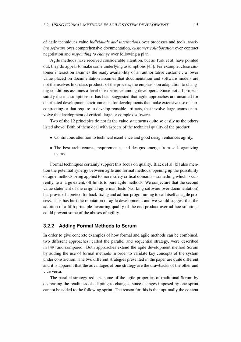
of agile techniques value Individuals and interactions over processes and tools, work-ing software over comprehensive documentation, customer collaboration over contractnegotiation and responding to change over following a plan.
Agile methods have received considerable attention, but as Turk et al. have pointedout, they do appear to make some underlying assumptions [43]. For example, close cus-tomer interaction assumes the ready availability of an authoritative customer; a lowervalue placed on documentation assumes that documentation and software models arenot themselves first-class products of the process; the emphasis on adaptation to chang-ing conditions assumes a level of experience among developers. Since not all projectssatisfy these assumptions, it has been suggested that agile approaches are unsuited fordistributed development environments, for developments that make extensive use of sub-contracting or that require to develop reusable artifacts, that involve large teams or in-volve the development of critical, large or complex software.
Two of the 12 principles do not fit the value statements quite so easily as the otherslisted above. Both of them deal with aspects of the technical quality of the product:
• Continuous attention to technical excellence and good design enhances agility.
• The best architectures, requirements, and designs emerge from self-organizingteams.
Formal techniques certainly support this focus on quality. Black et al. [5] also men-tion the potential synergy between agile and formal methods, opening up the possibilityof agile methods being applied to more safety critical domains – something which is cur-rently, to a large extent, off limits to pure agile methods. We conjecture that the secondvalue statement of the original agile manifesto (working software over documentation)has provided a pretext for hack-fixing and ad-hoc programming to call itself an agile pro-cess. This has hurt the reputation of agile development, and we would suggest that theaddition of a fifth principle favouring quality of the end product over ad-hoc solutionscould prevent some of the abuses of agility.
3.2.2 Adding Formal Methods to Scrum
In order to give concrete examples of how formal and agile methods can be combined,two different approaches, called the parallel and sequential strategy, were describedin [49] and compared. Both approaches extend the agile development method Scrumby adding the use of formal methods in order to validate key concepts of the systemunder constriction. The two different strategies presented in the paper are quite differentand it is apparent that the advantages of one strategy are the drawbacks of the other andvice versa.
The parallel strategy reduces some of the agile properties of traditional Scrum bydecreasing the readiness of adapting to changes, since changes imposed by one sprintcannot be added to the following sprint. The reason for this is that optimally the content
16 CHAPTER 3. DEVELOPMENT PROCESS FOR DISCRETE-EVENT SYSTEMS
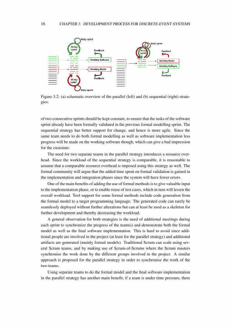
Figure 3.2: (a) schematic overview of the parallel (left) and (b) sequential (right) strate-gies.
of two consecutive sprints should be kept constant, to ensure that the tasks of the softwaresprint already have been formally validated in the previous formal modelling sprint. Thesequential strategy has better support for change, and hence is more agile. Since thesame team needs to do both formal modelling as well as software implementation lessprogress will be made on the working software though, which can give a bad impressionfor the customer.
The need for two separate teams in the parallel strategy introduces a resource over-head. Since the workload of the sequential strategy is comparable, it is reasonable toassume that a comparable resource overhead is imposed using this strategy as well. Theformal community will argue that the added time spent on formal validation is gained inthe implementation and integration phases since the system will have fewer errors.
One of the main benefits of adding the use of formal methods is to give valuable inputto the implementation phase, or to enable reuse of test cases, which in turn will lessen theoverall workload. Tool support for some formal methods include code generation fromthe formal model to a target programming language. The generated code can rarely beseamlessly deployed without further alterations but can at least be used as a skeleton forfurther development and thereby decreasing the workload.
A general observation for both strategies is the need of additional meetings duringeach sprint to synchronize the progress of the team(s) and demonstrate both the formalmodel as well as the final software implementation. This is hard to avoid since addi-tional people are involved in the project (at least for the parallel strategy) and additionalartifacts are generated (mainly formal models). Traditional Scrum can scale using sev-eral Scrum teams, and by making use of Scrum-of-Scrums where the Scrum masterssynchronise the work done by the different groups involved in the project. A similarapproach is proposed for the parallel strategy in order to synchronise the work of thetwo teams.
Using separate teams to do the formal model and the final software implementationin the parallel strategy has another main benefit; if a team is under time pressure, there
3.2. USING FORMAL METHODS IN AGILE SYSTEM DEVELOPMENT 17
is a danger of neglecting the formal modelling phase in order to ensure that enough timeis left for finishing the final implementation in each sprint. This danger is avoided whenhaving separate teams doing the formal model and the software implementation. On theother hand, having two separate teams working on the implementation and investigationtasks works against the agile principles of having self-contained teams.
3.2.3 Concluding Remarks
The improved analytic power of formal methods tools and greater understanding of therole of rigorous modelling in development processes are gradually improving softwarepractice. However, the claim that formal methods can be part of agile processes shouldnot be made lightly. We have examined the value statements and supporting principlesof the agile manifesto and have identified areas in which formal methods and tools arehard-pressed to live up to the claim that they can work with agile techniques. In doingso, we have drawn on our own experience of developing and deploying a tool-supportedformal method in industrial settings.
Formal methods should not be thought of as development processes, but are betterseen as collections of techniques that can be deployed as appropriate. For the agiledeveloper, it is not possible to get benefits from formalism unless the formal notation ortechnique is focused and easy to learn and apply. Luckily, formal modelling and analysisdoes not have to be burdensome. For example, forms of static analysis and automaticverification can be used to ensure that key properties are preserved from one iterationto the next. For this to be efficient, and to fit into the agile mindset, analysis must haveautomated tool support. Formalists should stop worrying about development processesif they want to support agility. Instead, they should start adjusting their ”only perfect isgood enough” mindset, and try a more lightweight approach to formal modelling if theirgoal is to become more agile.
Formalists may need to remember that most engineers, even good ones, have noprior experience of formal methods technology and demand tools that give answers toanalyses in seconds. Developers of formal methods must give serious attention to theirease of use if they are to claim any link with agile software development.
Tools must integrate almost seamlessly with existing development environments ifthey are to support agile processes and there is considerable research required to makethis a reality. Progress can certainly be made by improving tools, in particular in com-bining with GUI building tools and for automation of different forms of analysis. In factwe would like the agile thinking to go beyond the software to encompass collaborationbetween different engineering disciplines involved in a complex product development,as in the embedded systems domain [6].
The agile manifesto is not necessarily consistent with a view of formal methods ascorrect-by-construction development processes. However, there are good reasons forcombining agile principles with the formal techniques. Formal methods researchers
18 CHAPTER 3. DEVELOPMENT PROCESS FOR DISCRETE-EVENT SYSTEMS
and tool builders must, however, address some deficiencies if the benefits of such acollaborative approach are to be realised.
3.3 Industrial Case - VDM Model Development
A lightweight version of the parallel strategy mentioned above has already been tried outin practice [50], where the author worked as the only member of the formal modellingteam working in parallel with a large team of more than 25 software engineers imple-menting a significant upgrade to a self-defense system for fighter aircraft. The projectinvolved many upgrades to an existing system, whereas the formal modelling focused onan upgrade to the interpretation of messages sent between two subsystems using an ex-isting communication protocol. Executable models of both subsystems were modelled inVDM++ and a large test suite was used in order to exercise the use of the communicationprotocol. The result of these numerous tests were used to show the implications of theupgrade to the customer, and to ensure that no unfortunate side effects were introduced.
3.3.1 Case Description
When fighter pilots are flying missions in hostile territory, there is a risk of encounteringenemy anti-aircraft systems. To respond to these threats, the pilot can deploy differentcountermeasures. Since opposing anti aircraft systems are becoming increasingly so-phisticated, and on-board self-defense systems are also becoming more sophisticated,the fighter pilot is in need of assistance in choosing the optimal countermeasures strat-egy.
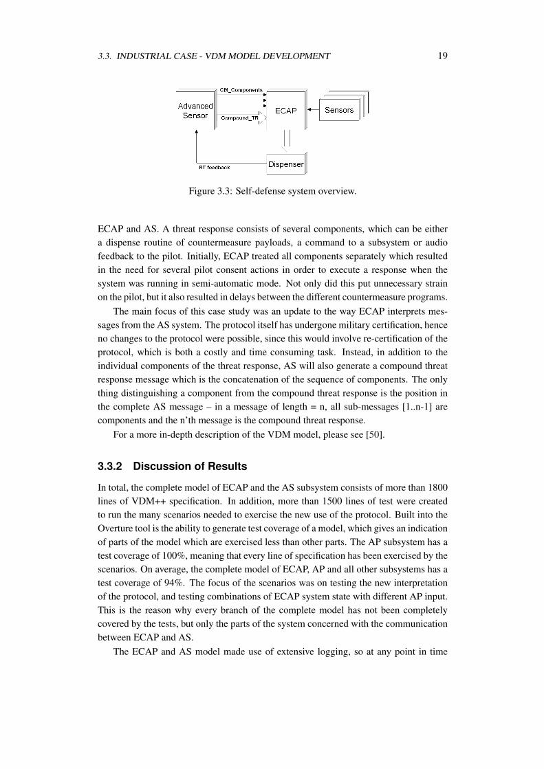
A system called Electronic Combat Adaptive Processor (ECAP) has been developedto assist the pilot in choosing the most optimal response to incoming threats. The sys-tem is a programmable unit that provides threat adaptive processing, threat evaluationand countermeasures strategy to counter incoming threats. From a multitude of sensorinputs (aircraft position, orientation, speed, altitude and threat type and incoming angleto name a few) the system chooses an effective combination of countermeasures againstthe incoming threat. The different sensors attached to ECAP can detect different typesof threats, and will report data of any incoming threat of that specific type to ECAP. Thechosen threat response, which can consist of one or more countermeasure programs, issent to a Dispenser subsystem which administers the deployment of the correct types ofdispense payloads with the correct timing. An overview of the system can be seen inFig. 3.3.
The subsystem of interest for this paper, is a special Advanced Sensor (AS). Thissensor not only detects incoming threats, but also calculates the countermeasures neededto avoid the threat. AS is running in parallel with the rest of the system, and relies onECAP to accept and execute generated threat responses. Hence, ECAP needs to checkthe RT and IAT of the proposed response for conflicts, and accept/reject the responsebased on this. A robust protocol has been specified, defining the communication between
3.3. INDUSTRIAL CASE - VDM MODEL DEVELOPMENT 19
Figure 3.3: Self-defense system overview.
ECAP and AS. A threat response consists of several components, which can be eithera dispense routine of countermeasure payloads, a command to a subsystem or audiofeedback to the pilot. Initially, ECAP treated all components separately which resultedin the need for several pilot consent actions in order to execute a response when thesystem was running in semi-automatic mode. Not only did this put unnecessary strainon the pilot, but it also resulted in delays between the different countermeasure programs.
The main focus of this case study was an update to the way ECAP interprets mes-sages from the AS system. The protocol itself has undergone military certification, henceno changes to the protocol were possible, since this would involve re-certification of theprotocol, which is both a costly and time consuming task. Instead, in addition to theindividual components of the threat response, AS will also generate a compound threatresponse message which is the concatenation of the sequence of components. The onlything distinguishing a component from the compound threat response is the position inthe complete AS message – in a message of length = n, all sub-messages [1..n-1] arecomponents and the n’th message is the compound threat response.
For a more in-depth description of the VDM model, please see [50].
3.3.2 Discussion of Results
In total, the complete model of ECAP and the AS subsystem consists of more than 1800lines of VDM++ specification. In addition, more than 1500 lines of test were createdto run the many scenarios needed to exercise the new use of the protocol. Built into theOverture tool is the ability to generate test coverage of a model, which gives an indicationof parts of the model which are exercised less than other parts. The AP subsystem has atest coverage of 100%, meaning that every line of specification has been exercised by thescenarios. On average, the complete model of ECAP, AP and all other subsystems has atest coverage of 94%. The focus of the scenarios was on testing the new interpretationof the protocol, and testing combinations of ECAP system state with different AP input.This is the reason why every branch of the complete model has not been completelycovered by the tests, but only the parts of the system concerned with the communicationbetween ECAP and AS.
The ECAP and AS model made use of extensive logging, so at any point in time
20 CHAPTER 3. DEVELOPMENT PROCESS FOR DISCRETE-EVENT SYSTEMS
the system state was available for post-execution analysis. The logfiles from the manyscenarios were used directly in the communication with the customer, to give a precisedescription of how the systems should react in the different situations. This was a greataid in agreeing on the way ECAP should interpret the countermeasure components andcompound threat response. In addition to these logs built directly into the model, acertain amount of logging is available in the Overture tool. The main focus of theseautomatically created logs is multi-threaded models, so mainly the scheduling of threadsis logged. If this automatic logging feature was to be extended into a more useful tool, itcould be very beneficial for the Overture tool in general, since users could avoid writingtheir own logging mechanism for each model.
The end customer was very impressed by the extensive tests which had been carriedout on the model, and the log files from the test proved to be a great communication toolbetween the customer and the systems engineers in charge of the project. The test resultsalso increased the confidence in the proposed solution for the development team.
For a system the size and complexity of the one presented here, it is very difficult (ifnot impossible) to analyse the many combinations of system state and AS input by hand.In addition the manual approach is very error prone, which could result in agreeing onerroneous behaviour and not discovering critical design flaws in the protocol. The testsuite composed for this project does not ensure complete coverage of the state-space ofthe system, but provided a simple framework enabling extension of other scenarios toanalyse some newly discovered corner-case. This ensured a short duration of the iterativecycles internally in the company when new corner cases had to be tested.
For the systems engineers leading the project, this was their first experience withformal methods, and in using executable models to specify functional requirements ingeneral:
”The possibility to run numerous scenarios to analyse different combi-nations of ECAP system state and AS input was invaluable, and the rapidfeedback from the model designer was very useful due to the time constraintsof the project. We are extremely happy with the results obtained from thiscase study, which helped us in reaching an agreement with the customerwithin a very limited period of time.”
The models of ECAP, AS and the protocol were developed by a single person over aperiod of just two months including knowledge gathering of the systems involved. Thiswas only possible due to the fact that a lot of details of the real system was abstractedaway, and only the main functionality of the systems was included in the model. Thedifferent subsystems are connected by a military standard communication bus, whichcould have been modelled in detail to test package collision etc. In addition, severalsubsystem commands to enable and disable various subsystems were omitted. This isindeed one of the main advantages of using system modelling in the early phases ofsystem development; describe the parts of the system of interest in detail and abstract
3.4. SUMMARY OF DISCRETE-EVENT WORK 21
away from any unneeded details. For example, low level implementation details of thedesired logic of various drivers is not needed to understand the overall functionality ofthe system – hence abstracting away from such details helps creating more readablemodels giving a better system overview.
3.4 Summary of Discrete-Event Work
The work presented in this chapter is focused on development of discrete-event models,which is a natural first step before adding the complexity of multi-domain models andco-simulation. On the methodology side of things, the step-wise development of VDM-RT models is described. In addition, the agile manifesto has been analysed in orderto determine how well formal methods support these principles and to discuss to whatextent the two different approaches to software development can be combined. A con-crete example of how formal methods can be used in the agile development frameworkScrum has been described, and a lightweight version of this strategy has been tried in anindustrial case.

Chapter 4
Development Process forMulti-Disciplinary Systems
Traditional development approaches are mono-disciplinary in style, in that separate me-chanical, electronic and software engineering groups handle distinct aspects of prod-uct development and often do so in sequence. Contemporary concurrent engineeringstrategies aim to improve the time to market by performing these activities in parallel.However, cross-cutting system-level requirements that cannot be assigned to a singlediscipline, such as performance and dependability, can cause great problems, becausetheir impact on each discipline is exposed late in the development process, usually dur-ing integration. Embedded systems, in which the viability of the product depends onthe close coupling between the physical and computing disciplines, therefore calls for amore multidisciplinary approach. My work in this area (so far) is described in [17].
4.1 Collaborative Modelling and Co-simulation
We conjecture that a collaborative methodology based on lightweight formal modellingimproves the chances of closing the design loop early, encouraging dialogue betweendisciplines and reducing errors, saving cost and time. Throughout the paper, we termthis approach ”collaborative modelling” or ”co-modelling”. In previous work [44], Ver-hoef has demonstrated that significant gains are feasible by combining VDM and BondGraphs, using co-simulation as the means of model assessment. Andrews et al. have sug-gested that collaborative models are suited to exploring fault behaviours [3]. We buildupon these results, indicating how a collaborative modelling approach can be realisedin existing formally-based technology, how models can be extended to describe formsof faulty behaviour, and identifying requirements for design space exploration in thiscontext.
23

24 CHAPTER 4. DEVELOPMENT PROCESS FOR MULTI-DISCIPLINARY SYSTEMS
A co-model (Figure 4.1 (a)) is a model composed of:
• Two component models, normally one describing a computing subsystem and onedescribing the plant or environment with which it interacts. The former modelis typically expressed in a discrete event (DE) formalism and the latter using acontinuous-time (CT) formalism.
• A contract, which identifies shared design parameters, shared variables, and com-mon events used to effect communication between the subsystems represented bythe models.
A co-model is itself a model and may be simulated under the control of a script.The simulation of a co-model is termed co-simulation. A co-model offers an interfacethat can be used to set design parameters and to run scripts to set initial values, triggerfaulty behaviour, provide external inputs and observe selected values as the simulationprogresses. Our goal is to provide modelling and simulation techniques that supportdesign space exploration, by which we mean the (iterative) process of constructing co-models, co-simulation and interpretation of test results governing the selection of alter-native models and co-models as the basis for further design steps.
Figure 4.1: (a) conceptual view of a co-model (left) and (b) execution of a co-modelrealised using a co-simulation engine (right).
In a co-simulation, a shared variable is a variable that appears in and can be accessedfrom both component models. Predicates over the variables in the component modelsmay be stated and may change value as the co-simulation progresses. The changing ofthe logical value of a predicate at a certain time is termed an event. Events are referredto by name and can be propagated from one component model to another within a co-model during co-simulation. The semantics of a co-simulation is defined in terms of theevolution of these shared variable changes and event occurrences while co-model time ispassing. In a co-simulation, the CT and DE models execute as interleaved threads of con-trol in their respective simulators under the supervision of a co-simulation engine (Fig-ure 4.1 (b)). The DE simulator calculates the smallest time ∆t it can run before it canperform the next possible action. This time step is used by the co-simulation engine inthe communication to the CT simulator which then runs the solver forward by up to ∆t .
4.1. COLLABORATIVE MODELLING AND CO-SIMULATION 25
If the CT simulator observes an event, for example when a continuously varying valuepasses a threshold, this is communicated back to the DE simulator by the co-simulationengine. If this event occurred prior to ∆t , then the DE simulator does not completethe full time step, but it runs forward to this shorter time step and then re-evaluates itssimulator state. Note that it is not possible (in general) to roll the DE simulation back,owing to the expense of saving the full state history, whereas the CT solver can workto specified times analytically. Verhoef et al. [46] provide an integrated operational se-mantics for the co-simulation of DE models with CT models. Co-simulation soundnessis ensured by enforcing strict monotonically increasing model time and a transactionmechanism that manages time triggered modification of shared variables.
The work reported in this paper is aimed at demonstrating the feasibility of multidis-ciplinary collaborative modelling for early-stage design space exploration. As a proof ofconcept, methods and an open tools platform are being developed to support modellingand co-simulation, with explicit modelling of faults and fault-tolerance mechanismsfrom the outset. This activity is undertaken as part of the EU FP7 Project DESTECS.
The proof of concept work uses continuous-time models expressed as differentialequations in Bond Graphs [26] and discrete event models expressed using the ViennaDevelopment Method (VDM) [14, 15] notation. The simulation engines supporting thetwo notations are, respectively, 20-sim [8] ∗ and Overture [29] †.
4.1.1 Basic Co-simulation in 20-sim and VDM
dV
dt= ϕin -ϕout (4.1)
ϕout =
{ ρ∗gA∗R ∗ V if valve open0 if valve closed
(4.2)
Figure 4.2: Water tank level controller case study system overview
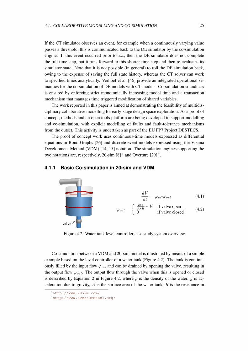
Co-simulation between a VDM and 20-sim model is illustrated by means of a simpleexample based on the level controller of a water tank (Figure 4.2). The tank is continu-ously filled by the input flow ϕin , and can be drained by opening the valve, resulting inthe output flow ϕout . The output flow through the valve when this is opened or closedis described by Equation 2 in Figure 4.2, where ρ is the density of the water, g is ac-celeration due to gravity, A is the surface area of the water tank, R is the resistance in
∗http://www.20sim.com/†http://www.overturetool.org/
26 CHAPTER 4. DEVELOPMENT PROCESS FOR MULTI-DISCIPLINARY SYSTEMS
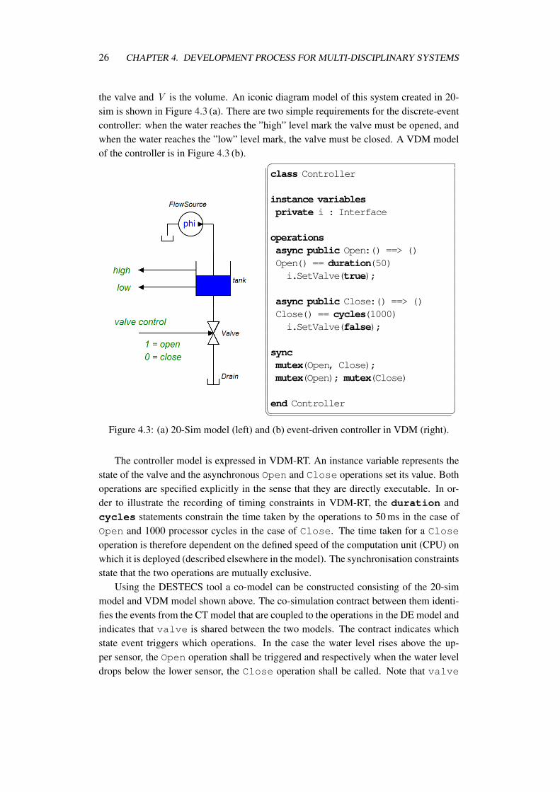
the valve and V is the volume. An iconic diagram model of this system created in 20-sim is shown in Figure 4.3 (a). There are two simple requirements for the discrete-eventcontroller: when the water reaches the ”high” level mark the valve must be opened, andwhen the water reaches the ”low” level mark, the valve must be closed. A VDM modelof the controller is in Figure 4.3 (b). �
class Controller
instance variablesprivate i : Interface
operationsasync public Open:() ==> ()Open() == duration(50)i.SetValve(true);
async public Close:() ==> ()Close() == cycles(1000)i.SetValve(false);
syncmutex(Open, Close);mutex(Open); mutex(Close)
end Controller� �Figure 4.3: (a) 20-Sim model (left) and (b) event-driven controller in VDM (right).
The controller model is expressed in VDM-RT. An instance variable represents thestate of the valve and the asynchronous Open and Close operations set its value. Bothoperations are specified explicitly in the sense that they are directly executable. In or-der to illustrate the recording of timing constraints in VDM-RT, the duration andcycles statements constrain the time taken by the operations to 50 ms in the case ofOpen and 1000 processor cycles in the case of Close. The time taken for a Closeoperation is therefore dependent on the defined speed of the computation unit (CPU) onwhich it is deployed (described elsewhere in the model). The synchronisation constraintsstate that the two operations are mutually exclusive.
Using the DESTECS tool a co-model can be constructed consisting of the 20-simmodel and VDM model shown above. The co-simulation contract between them identi-fies the events from the CT model that are coupled to the operations in the DE model andindicates that valve is shared between the two models. The contract indicates whichstate event triggers which operations. In the case the water level rises above the up-per sensor, the Open operation shall be triggered and respectively when the water leveldrops below the lower sensor, the Close operation shall be called. Note that valve
4.2. TOOLS 27
represents the actual state of the valve, not merely the controller’s view of it.
4.2 Tools
In addition to the DESTECS tool described above, multiple other tools have been testedand compared in order to find limitations in their co-simulation capabilities. Initially,four mainly continuous-time simulation tools were compared in order to investigate ini-tial learning curve and usability. The four different tools were chosen based on thefollowing criteria. Matlab/Simulink was chosen since it is widely used in the industry –MathWorks claim that more than 1million engineers worldwide use the tool. As a freealternative, the open-source tool Scilab/Xcos was chosen. This tool is by many knownas the ”Open-source version of Matlab”. 20-sim has its roots in academia but is nowmaintained by the company Controllab Products B.V. which is an off-spring companyfrom the Control Engineering Group at Twente University. It was chosen as an exampleof an academic tool which has successfully moved into industry. Finally, Ptolemy II waschosen as a purely academic tool developed and maintained by the Center for Hybridand Embedded Software Systems (CHESS) at University of California at Berkeley.
The watertank case described above was modelled in all four tools. In addition, themodel was extended with an additional cascade coupled watertank where the output ofone tank is the input to the other. This addition was created in order to test how well thedifferent tools support model reuse and extensions to existing models.
Each of the four tools were evaluated based on a number of criteria, like: learningcurve, usability, model extension support, model component reuse, simulation resultvisualisation and accessibility of tutorials and model examples. As is clear, there wasgreat focus on usability aspects in this initial survey.
Of the four tools, only Ptolemy is really suited for stand-alone co-simulation, so amore in-depth investigation has been initiated comparing the co-simulation capabilitiesof the DESTECS and the Ptolemy tools. In this comparison a model of a fuel systemfor aircrafts will be modelled, where fuel will be transfered between several on-boardfuel tanks. This comparison will focus less on usability and more on co-simulationcapabilities like:
Simulation speed: Running the same simulation on the two tools, which is the fastest?
Continuous-time simulation settings: Which ordinary differential equation (ODE ) sol-vers can be chosen? Can the stepsize of the solver be changed freely?
Discrete-event controller expressiveness: How well does the discrete-event part of thetools support abstraction? Is it possible to describe a hierarchical or object orientedcontroller?
Fault modelling: How well do the tools support modelling faults and error correctingcontrollers?
28 CHAPTER 4. DEVELOPMENT PROCESS FOR MULTI-DISCIPLINARY SYSTEMS
This work is far from concluded, and only the initial modelling work has begun.Collaborating with post-docs from Berkeley University and Newcastle University willensure that the comparison is fair and that the results are validated by both Ptolemy andDESTECS representatives.
4.3 Casework
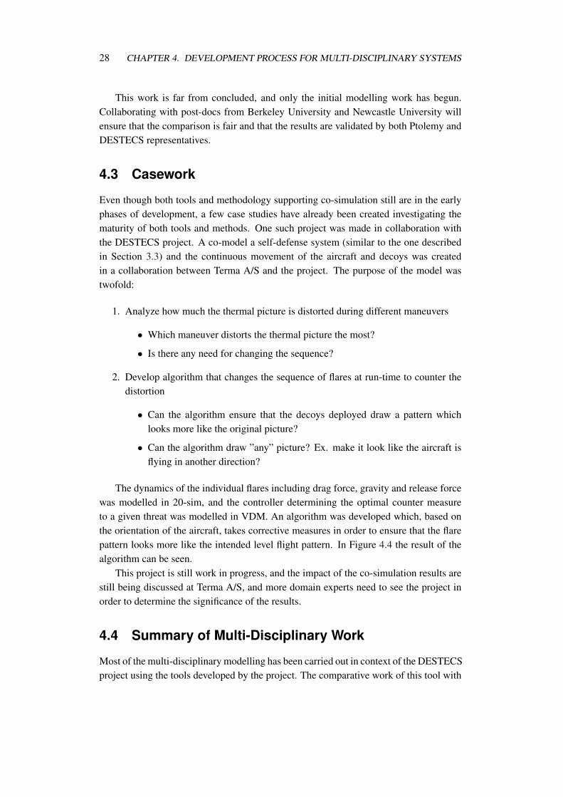
Even though both tools and methodology supporting co-simulation still are in the earlyphases of development, a few case studies have already been created investigating thematurity of both tools and methods. One such project was made in collaboration withthe DESTECS project. A co-model a self-defense system (similar to the one describedin Section 3.3) and the continuous movement of the aircraft and decoys was createdin a collaboration between Terma A/S and the project. The purpose of the model wastwofold:
1. Analyze how much the thermal picture is distorted during different maneuvers
• Which maneuver distorts the thermal picture the most?
• Is there any need for changing the sequence?
2. Develop algorithm that changes the sequence of flares at run-time to counter thedistortion
• Can the algorithm ensure that the decoys deployed draw a pattern whichlooks more like the original picture?
• Can the algorithm draw ”any” picture? Ex. make it look like the aircraft isflying in another direction?
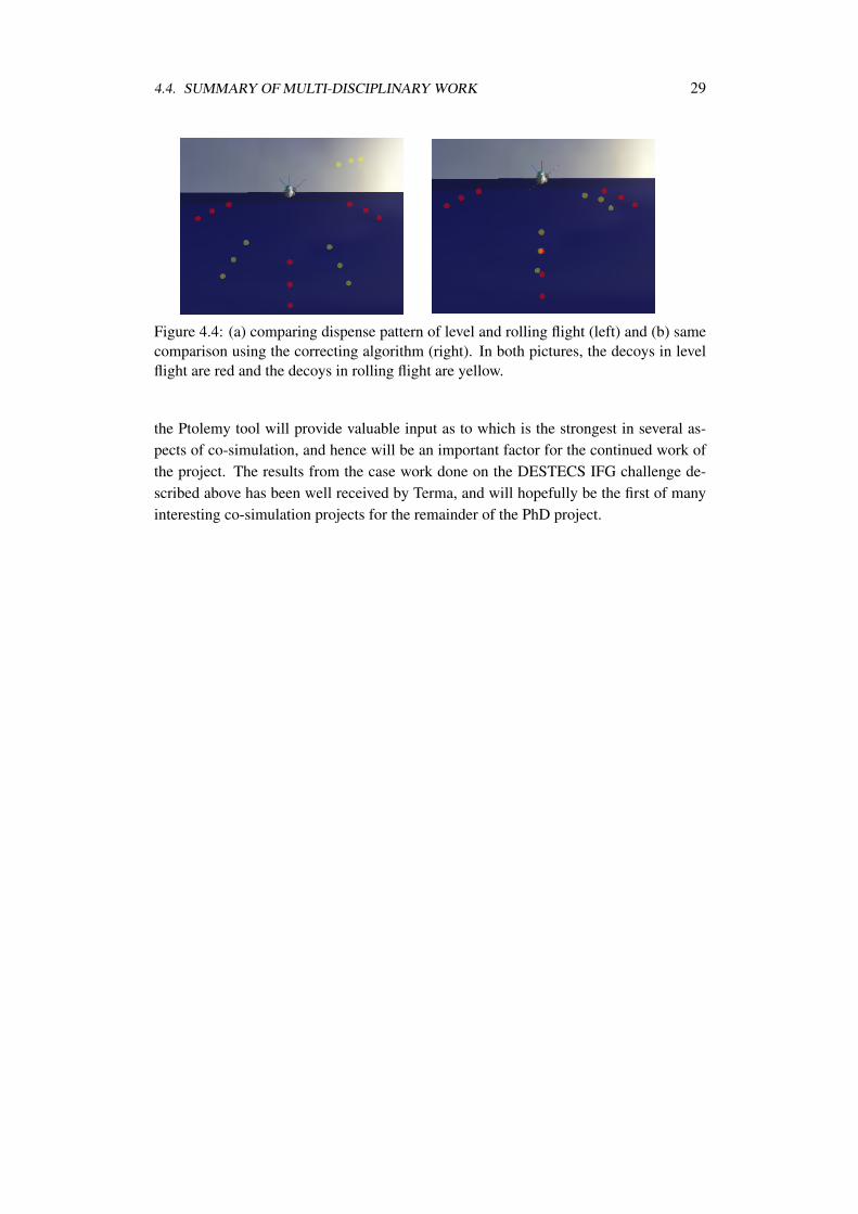
The dynamics of the individual flares including drag force, gravity and release forcewas modelled in 20-sim, and the controller determining the optimal counter measureto a given threat was modelled in VDM. An algorithm was developed which, based onthe orientation of the aircraft, takes corrective measures in order to ensure that the flarepattern looks more like the intended level flight pattern. In Figure 4.4 the result of thealgorithm can be seen.
This project is still work in progress, and the impact of the co-simulation results arestill being discussed at Terma A/S, and more domain experts need to see the project inorder to determine the significance of the results.
4.4 Summary of Multi-Disciplinary Work
Most of the multi-disciplinary modelling has been carried out in context of the DESTECSproject using the tools developed by the project. The comparative work of this tool with
4.4. SUMMARY OF MULTI-DISCIPLINARY WORK 29
Figure 4.4: (a) comparing dispense pattern of level and rolling flight (left) and (b) samecomparison using the correcting algorithm (right). In both pictures, the decoys in levelflight are red and the decoys in rolling flight are yellow.
the Ptolemy tool will provide valuable input as to which is the strongest in several as-pects of co-simulation, and hence will be an important factor for the continued work ofthe project. The results from the case work done on the DESTECS IFG challenge de-scribed above has been well received by Terma, and will hopefully be the first of manyinteresting co-simulation projects for the remainder of the PhD project.

Chapter 5
Summary and Future Work
The main goal of the PhD project is to describe and validate a development process formulti-disciplinary embedded systems. This chapter gives a summary of the work carriedout so far, as well as an outline of the work planned for the remainder of the project.
5.1 Summary of Work
As an Industrial PhD student, the interests of the company (Terma A/S) needs to betaken into account. Since Terma has no experience in using a model driven developmentprocess, it was clear that moving directly to co-simulation of both discrete-event andcontinuous-time models was to big a jump. Instead the modelling concepts were initiallyintroduced in the discrete domain only.
5.1.1 Discrete-event Modelling
A methodology of how to develop and refine VDM models was initially describedin [31]. Here requirements are captured in a VDM-SL model, describing only the keyfunctionality of the system. Following this, an object oriented architecture is described ina sequential VDM++ model, and concurrency constraints are described in a concurrentVDM++ model. Finally, a VDM-RT model is created in order to describe distributionand real-time constraints of the system.
Since agile methods have gained a lot of acceptance in industry (Terma uses a heavilytailored Scrum process in their day-to-day software development) this topic were alsoinvestigated. In [32] we discussed how different agile methods and light weight formalmethods really are, and argue that the two approaches to software development can becombined if both the agile and formal community are ready to adjust their ideals slightly.Each of the 12 agile principles are analysed and it is argued how light weight formal
31
32 CHAPTER 5. SUMMARY AND FUTURE WORK
models can be used to support these principles. In [49] a concrete example of adding theuse of formal methods to the agile development process Scrum is described.
The work on the discrete-event model development methodologies is supported bythe case work on the self-defense system for fighter aircraft described in [50]. In thiscase, a concurrent VDM++ model was used to describe the behaviour of a proposed ex-tension to a complex counter measure system. The incremental model development pro-cess was used, moving from a sequential to a concurrent model, and one of the strategiesof combining formal methods with Scrum described in [49] was used. This case workgave good confidence in the methods described.
5.1.2 Multi-domain Modelling
There is only a limited choice when it comes to co-simulation tools. I have used the toolsdeveloped in the DESTECS project the most for multi domain modelling, but a two weekvisit to Berkeley University has also given a good understanding of the Ptolemy tool. Inorder to determine pros and cons of the two tools, an in depth comparison has beeninitiated with collaboration from Berkeley and the DESTECS project.
Numerous smaller co-simulation models have been developed in order to get com-fortable with the tools, and in order to take the initial steps towards describing a firstversion of a multi-disciplinary development process. The DESTECS IFG challenge de-scribed in Section 4.3 is the most extensive co-model created.
5.2 Future Work
This section gives a brief overview of some of the projects planned for the second halfof the PhD project. Some of this work has already been initiated, while other areas aremainly suggested areas of interest.
5.2.1 Methodology
The main focus of the second half of the PhD project is on describing and testing amulti-domain development process utilising co-simulation of different domain specificmodels. This work has already been initiated, and a brief overview of the initial phases isgiven below. It is important to note that this is very early work in progress which mightbe changed later in the project.
Model purpose It is very important to have a well defined purpose of a model, in orderto determine which details are important and which can be abstracted away. Inorder to make a systematic progression from the model purpose to an initial systemmodel, the Requirement Diagrams of the system modelling language SysML [42]is used for this. A single main purpose of the system model is defined, and severalsub-purposes can be derived or refined from this in a hierarchical manner. This
5.2. FUTURE WORK 33
will help defining the necessary main parts of the system model in the followingphase.
System overview Using the SysML Block Definition Diagrams the main blocks of thesystem are derived from the Requirement Diagram from the previous phase. Thedifferent blocks are connected using flowports in order to define the direction ofdata flow between the different blocks.
Detailed view For each of the main parts of the system overview model, a SysML Inter-nal Block Diagram is created in order to describe more details of the sub-systems.Here it is very important to define the interface between the different models ingreat details, since this will be the basis of the contract describing the interfacebetween models from different domains. At this point, it should also be madeexplicit which blocks are software (to be modelled in the discrete-event domain)and which blocks are mechanics or physical phenomena (to be modelled in thecontinuous-time domain).
These initial phases will help translating system requirements into more detailedmono-disciplinary design decisions which is often a huge challenge when developingmulti-disciplinary systems. Dividing the complete system overview into several sub-systems also ensures that smaller incremental steps can be taken in the model develop-ment.
A lot of work is still needed, and as said above this is the main focus of the remainderof the PhD project. It is also the plan to have students try out and evaluate the method insmall multi-disciplinary groups consisting of IT and mechanics engineers for example.
5.2.2 Tools
As already mentioned a comparison of the DESTECS and the Ptolemy tools has beeninitiated. In addition, a Danish developed game engine called Unity∗ will be tested asan alternative low-fidelity modelling tool using the build-in PhysX engine for simplereal-time rigid body simulations. Comparing this approach to a high-fidelity simulationengine like 20-sim will determine if the results of the real-time simulations made byPhysX are ”good enough” for certain continuous systems, like the modelling of thetrajectory of decoys in the DESTECS IFG challenge. Early results, comparing the outputof a simple gravity model and a spring/damper system, shows great promise (only about3% inaccuracy close to signal peaks), but more in-depth work is still needed.
5.2.3 Case work
A new industrial case for Terma A/S has been started June 2011. Here a large combi-nation of several discrete-event and continuous-time models will be combined in order
∗http://www.unity3d.com/
34 CHAPTER 5. SUMMARY AND FUTURE WORK
to model a self-defense system for battleships. This co-model will include the followingcomponents:
Missile A continuous-time model of the movement of the missile describing maximumspeed and minimum turn radius, and a discrete-event model of the tracking algo-rithm trying to lead the missile to its target.
Battleship A continuous-time model of the movement of the ship describing maximumspeed and maneuverability, and a discrete-event model of the counter measuresoftware onboard, calculating most optimal response to an incoming threat.
Decoys A continuous-time model describing the trajectory of dispensed decoys, andhow the wind affects this.
This will be a large and complex model including a lot of interesting issues, and willbe perfect for trying out the methodology defined.
5.3 Concluding Remarks
This report describes the main activities of the first half of my PhD studies, which isconcerned with co-simulation of multi-domain models using in embedded system devel-opment. I have given concrete examples of the work done as well as the eight papersproduced during the first year and a half. A lot of this work has been centered aroundsingle-domain modelling mainly in the discrete-event domain, since it was decided thatthis was a necessary first step towards multi-domain modelling.
In addition, I have outlined possible future research areas. Here it is the plan to leavethe single-domain modelling and focus on co-simulation methodology and case studies.
Bibliography
[1] Abrahamsson, P., Salo, O., Ronkainen, J., Warsta, J.: Agile software developmentmethods Review and analysis. Tech. Rep. 478, VTT Technical Research Centre ofFinland (2002) [cited at p. 14]
[2] Alur, R., Henzinger, T.A., Ho, P.H.: Automatic symbolic verification of embed-ded systems. IEEE Transactions on Software Engineering 22, 181–201 (1996)[cited at p. 9]
[3] Andrews, Z.H., Fitzgerald, J.S., Verhoef, M.: Resilience Modelling through Dis-crete Event and Continuous Time Co-Simulation. In: Proc. 37th Annual IFIP/IEEEIntl. Conf. on Dependable Systems and Networks (Supp. Volume). pp. 350–351.IEEE Computer Society (June 2007) [cited at p. 23]
[4] Bjørner, D., Jones, C. (eds.): The Vienna Development Method: The Meta-Language, Lecture Notes in Computer Science, vol. 61. Springer-Verlag (1978)[cited at p. 7, 12]
[5] Black, S., Boca, P.P., Bowen, J.P., Gorman, J., Hinchey, M.: Formal versus agile:Survival of the fittest? IEEE Computer 42(9), 37–45 (September 2009) [cited at p. 15]
[6] Broenink, J.F., Larsen, P.G., Verhoef, M., Kleijn, C., Jovanovic, D., Pierce, K.,F., W.: Design support and tooling for dependable embedded control software. In:Proceedings of Serene 2010 International Workshop on Software Engineering forResilient Systems. ACM (April 2010) [cited at p. 9, 17]
[7] Broenink, J.F.: Computer-aided physical-systems modeling and simulation: abond-graph approach. Ph.D. thesis, Faculty of Electrical Engineering, Universityof Twente, Enschede, Netherlands (1990) [cited at p. 8]
[8] Broenink, J.F.: Modelling, Simulation and Analysis with 20-Sim. Journal A Spe-cial Issue CACSD 38(3), 22–25 (1997) [cited at p. 8, 25]
35
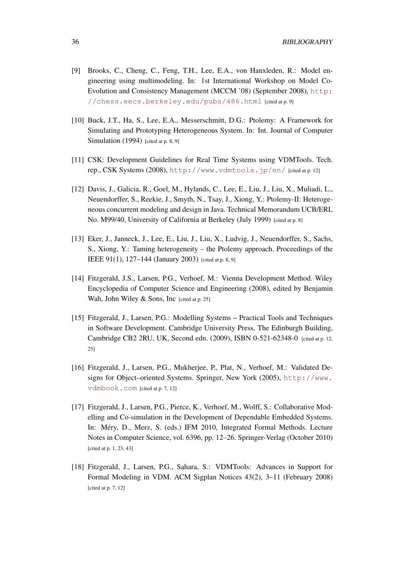
36 BIBLIOGRAPHY
[9] Brooks, C., Cheng, C., Feng, T.H., Lee, E.A., von Hanxleden, R.: Model en-gineering using multimodeling. In: 1st International Workshop on Model Co-Evolution and Consistency Management (MCCM ’08) (September 2008), http://chess.eecs.berkeley.edu/pubs/486.html [cited at p. 9]
[10] Buck, J.T., Ha, S., Lee, E.A., Messerschmitt, D.G.: Ptolemy: A Framework forSimulating and Prototyping Heterogeneous System. In: Int. Journal of ComputerSimulation (1994) [cited at p. 8, 9]
[11] CSK: Development Guidelines for Real Time Systems using VDMTools. Tech.rep., CSK Systems (2008), http://www.vdmtools.jp/en/ [cited at p. 12]
[12] Davis, J., Galicia, R., Goel, M., Hylands, C., Lee, E., Liu, J., Liu, X., Muliadi, L.,Neuendorffer, S., Reekie, J., Smyth, N., Tsay, J., Xiong, Y.: Ptolemy-II: Heteroge-neous concurrent modeling and design in Java. Technical Memorandum UCB/ERLNo. M99/40, University of California at Berkeley (July 1999) [cited at p. 8]
[13] Eker, J., Janneck, J., Lee, E., Liu, J., Liu, X., Ludvig, J., Neuendorffer, S., Sachs,S., Xiong, Y.: Taming heterogeneity – the Ptolemy approach. Proceedings of theIEEE 91(1), 127–144 (January 2003) [cited at p. 8, 9]
[14] Fitzgerald, J.S., Larsen, P.G., Verhoef, M.: Vienna Development Method. WileyEncyclopedia of Computer Science and Engineering (2008), edited by BenjaminWah, John Wiley & Sons, Inc [cited at p. 25]
[15] Fitzgerald, J., Larsen, P.G.: Modelling Systems – Practical Tools and Techniquesin Software Development. Cambridge University Press, The Edinburgh Building,Cambridge CB2 2RU, UK, Second edn. (2009), ISBN 0-521-62348-0 [cited at p. 12,
25]
[16] Fitzgerald, J., Larsen, P.G., Mukherjee, P., Plat, N., Verhoef, M.: Validated De-signs for Object–oriented Systems. Springer, New York (2005), http://www.vdmbook.com [cited at p. 7, 12]
[17] Fitzgerald, J., Larsen, P.G., Pierce, K., Verhoef, M., Wolff, S.: Collaborative Mod-elling and Co-simulation in the Development of Dependable Embedded Systems.In: Mery, D., Merz, S. (eds.) IFM 2010, Integrated Formal Methods. LectureNotes in Computer Science, vol. 6396, pp. 12–26. Springer-Verlag (October 2010)[cited at p. 1, 23, 43]
[18] Fitzgerald, J., Larsen, P.G., Sahara, S.: VDMTools: Advances in Support forFormal Modeling in VDM. ACM Sigplan Notices 43(2), 3–11 (February 2008)[cited at p. 7, 12]
BIBLIOGRAPHY 37
[19] Fritzson, P., Engelson, V.: Modelica - a unified object-oriented language for sys-tem modelling and simulation. In: ECCOP ’98: Proceedings of the 12th Euro-pean Conference on Object-Oriented Programming. pp. 67–90. Springer-Verlag(1998), http://www.modelica.org/documents/ModelicaSpec32.
pdf [cited at p. 8]
[20] Goonatilake, S., Khebbal, S. (eds.): Intelligent Hybrid Systems. John Wiley &Sons, Inc., New York, NY, USA (1994) [cited at p. 5]
[21] H.Bekic, D.Bjørner, W.C.P.: A formal definition of a pl/i subset. Tech. Rep. 25.139,IBM Laboratory, Vienna (December 1974) [cited at p. 7]
[22] Henzinger, T.: The theory of hybrid automata. In: M.K. Inan, R.K. (ed.) Proceed-ings of the 11th Annual Symposium on Logic in Computer Science (LICS). pp.278–292. IEEE Computer Society Press (1996) [cited at p. 5]
[23] Henzinger, T.A., Sifakis, J.: The embedded systems design challenge. In: FM2006: Formal Methods, 14th International Symposium on Formal Methods, Hamil-ton, Canada, August 21-27, 2006, Proceedings. pp. 1–15 (2006) [cited at p. 3]
[24] Henzinger, T., Sifakis, J.: The Discipline of Embedded Systems Design. IEEEComputer 40(10), 32–40 (October 2007) [cited at p. 3]
[25] Jones, C.B.: Systematic Software Development Using VDM. Prentice-Hall Inter-national, Englewood Cliffs, New Jersey, second edn. (1990), iSBN 0-13-880733-7[cited at p. 12]
[26] Karnopp, D., Rosenberg, R.: Analysis and simulation of multiport systems: thebond graph approach to physical system dynamic. MIT Press, Cambridge, MA,USA (1968) [cited at p. 8, 25]
[27] Kurita, T., Nakatsugawa, Y.: The Application of VDM++ to the Development ofFirmware for a Smart Card IC Chip. Intl. Journal of Software and Informatics 3(2-3) (October 2009) [cited at p. 7]
[28] Kurita, T., Chiba, M., Nakatsugawa, Y.: Application of a Formal Specification Lan-guage in the Development of the “Mobile FeliCa” IC Chip Firmware for Embed-ding in Mobile Phone. In: Cuellar, J., Maibaum, T., Sere, K. (eds.) FM 2008: For-mal Methods. pp. 425–429. Lecture Notes in Computer Science, Springer-Verlag(May 2008) [cited at p. 7]
[29] Larsen, P.G., Battle, N., Ferreira, M., Fitzgerald, J., Lausdahl, K., Verhoef, M.:The Overture Initiative – Integrating Tools for VDM. ACM Software EngineeringNotes 35(1) (January 2010) [cited at p. 7, 25]
38 BIBLIOGRAPHY
[30] Larsen, P.G., Fitzgerald, J.: Recent Industrial Applications of VDM in Japan. In:Boca, B., Larsen (eds.) FACS 2007 Christmas Workshop: Formal Methods in In-dustry. BCS, eWIC (December 2007) [cited at p. 7]
[31] Larsen, P.G., Fitzgerald, J., Wolff, S.: Methods for the Development of DistributedReal-Time Systems using VDM. International Journal of Software and Informatics3(2-3) (October 2009) [cited at p. 1, 11, 14, 31, 43]
[32] Larsen, P.G., Fitzgerald, J., Wolff, S.: Are formal methods ready for agility? a real-ity check. In: Gruner, S., Rumpe, B. (eds.) 2nd International Workshop on FormalMethods and Agile Methods. pp. 13–25. Lecture Notes in Informatics (September2010), iSSH 1617-5468 [cited at p. 1, 11, 31, 43]
[33] Larsen, P.G., Lausdahl, K., Ribeiro, A., Wolff, S., Battle, N.: Overture VDM-10 Tool Support: User Guide. Tech. Rep. TR-2010-02, The Overture Initiative,www.overturetool.org (May 2010) [cited at p. 43]
[34] MathWorks: http://www.mathworks.com (2010) [cited at p. 8]
[35] Mukherjee, P., Bousquet, F., Delabre, J., Paynter, S., Larsen, P.G.: ExploringTiming Properties Using VDM++ on an Industrial Application. In: Bicarregui, J.,Fitzgerald, J. (eds.) Proceedings of the Second VDM Workshop (September 2000),Available at www.vdmportal.org [cited at p. 7]
[36] Nagel, L., Pederson, D.O.: Simulation program with integrated circuit emphasis(SPICE). Tech. Rep. ERL-M382, University of California, Berkeley, ElectronicsResearch Laboratory, CA, USA (1973) [cited at p. 8]
[37] Overture-Core-Team: Overture Web site. http://www.overturetool.org (2007)[cited at p. 12]
[38] Parnas, D., Clements, P.: A Rational Design Process: How and Why to Fake It.IEEE Transactions on Software Engineering 12(2) (February 1986) [cited at p. 14]
[39] Peter Gorm Larsen, Sune Wolff, N.B.J.F., Pierce, K.: Development process ofdistributed embedded systems using vdm. Tech. Rep. TR-2010-02, The OvertureOpen Source Initiative (April 2010) [cited at p. 1, 11, 43]
[40] Plat, N., Larsen, P.G.: An Overview of the ISO/VDM-SL Standard. Sigplan No-tices 27(8), 76–82 (August 1992) [cited at p. 7]
[41] Saiedian, H.: An invitation to formal methods. IEEE Computer 29(4), 16–30 (April1996), roundtable with contributions from experts [cited at p. 14]
[42] Systems modeling language (sysml) specification. Tech. Rep.Version 1.0, SysML Modelling team (November 2005),
BIBLIOGRAPHY 39
http://www.sysml.org/artifacts/specs/SysMLv1.0a-051114R1.pdf [cited at p. 7,
32]
[43] Turk, D., France, R., Rumpe, B.: Limitations of agile software processes. In:Proceedings of the 3rd international Conference on Extreme Programming andFlexible Processes in Software Engineering (XP2002). pp. 43–46 (May 2002)[cited at p. 15]
[44] Verhoef, M.: Modeling and Validating Distributed Embedded Real-Time Con-trol Systems. Ph.D. thesis, Radboud University Nijmegen (2008), ISBN 978-90-9023705-3 [cited at p. 23]
[45] Verhoef, M., Larsen, P.G., Hooman, J.: Modeling and Validating Distributed Em-bedded Real-Time Systems with VDM++. In: Misra, J., Nipkow, T., Sekerinski,E. (eds.) FM 2006: Formal Methods. pp. 147–162. Lecture Notes in ComputerScience 4085 (2006) [cited at p. 7]
[46] Verhoef, M., Visser, P., Hooman, J., Broenink, J.: Co-simulation of Real-timeEmbedded Control Systems. In: Davies, J., Gibbons, J. (eds.) Integrated FormalMethods: Proc. 6th. Intl. Conference. pp. 639–658. Lecture Notes in ComputerScience 4591, Springer-Verlag (July 2007) [cited at p. 25]
[47] Wing, J.M.: A Specifier’s Introduction to Formal Methods. IEEE Computer 23(9),8–24 (September 1990) [cited at p. 6]
[48] Wolff, S.: Formalising Concurrent and Distributed Design Patterns with VDM(November 2009), the 7th Overture workshop at FM’09 [cited at p. 1, 43]
[49] Wolff, S.: Agile Methods for Safety-Critical Systems – Scrum Goes Formal (July2011), submitted to Journal of Systems and Software – special issue on a unifiedview of agile software development [cited at p. 1, 11, 15, 32, 43]
[50] Wolff, S.: Using Executable VDM++ Models in an Industrial Application - Self-defence System for Fighter Aircraft. Technical report, Aarhus School of Engineer-ing (June 2011) [cited at p. 1, 11, 18, 19, 32, 43]
[51] Wolff, S., Larsen, P.G., Noergaard, T.: Development Process for Multi-Disciplinary Embedded Control Systems. In: EuroSim 2010. EuroSim (September2010) [cited at p. 1, 3, 43]
[52] Woodcock, J., Larsen, P.G., Bicarregui, J., Fitzgerald, J.: Formal Methods: Practiceand Experience. ACM Computing Surveys 41(4), 1–36 (October 2009) [cited at p. 14]
[53] Wu, B., Bogaerts, A.: Scilab - a simulation environment for the scalable coherentinterface. In: MASCOTS 95: Proceedings of the Third International Workshop onModeling, Analysis and Simulation of Computer and Telecommunication Systems.pp. 242–247 (January 1995) [cited at p. 8]


Appendices
41

Appendix A
My Publications
A.1 Methodology
1. Methods for the Development of Distributed Real-Time Systems using VDM [31]
2. Development Process for Multi-Disciplinary Embedded Control Systems [51]
3. Formalising Agility – Scrum Goes Formal [49]
A.2 Cases
4. Using Executable VDM++ Models in an Industrial Application – Self-defenseSystem for Fighter Aircraft [50]
A.3 Overture
5. Development Process of Distributed Embedded Systems using VDM [39]
6. Overture VDM-10 Tool Support: User Guide [33]
A.4 Misc
7. Formalising Concurrent and Distributed Design Patters with VDM [48]
8. Are Formal Methods Ready for Agility? A Reality Check [32]
9. Collaborative Modelling and Co-simulation in the Development of DependableEmbedded Systems [17]
43

Appendix B
Courses Completed
During the first half of my Ph.D. studies I have completed the following courses (a totalof 33.2 ECTS points):
Business Course: Mandatory 7.5 ECTS point course that all Industrial Ph.D. studentshave to complete. The course was arranged by the consulting company Haslund& Alsted in collaboration with the Danish Agency for Science Technology andInnovation and gave a broad introduction to topics like intellectual property rights,innovation, management strategies, etc.
Writing and Reviewing Scentific Papers: A 3.7 ECTS point course held by AalborgUniversity. Theory like the IMRAD structure (introduction, method, results anddiscussion) was tried out in practice where all course participants had to provide ashort paper describing the topic of their Ph.D. project.
Compiler: A 10 ECTS point course held at the Computer Science department of AarhusUniversity. A compiler for a sub-set of Java was developed including parser, typechecker, static analysis, code generation and code optimization. This course gavea very in-depth understanding of the structure of object-oriented languages.
Systems Engineering: A 5 ECTS point course held at Aarhus School of Engineering.Topics like requirements, development cycle, design synthesis, system verifica-tion, project planning, resource management and risk management were includedin the curriculum of this course. Since I have worked with several systems engi-neers at Terma A/S I found it important to understand their world better.
Hardware/Software Co-design: A 5 ECTS point course held at Aarhus School of En-gineering. The course provides a thorough introduction to the methods and tech-niques for hardware-software co-design to modern digital electronics such as FP-GAs.
45

46 APPENDIX B. COURSES COMPLETED
Modelchecking: A short 2 ECTS point course arranged by the Computer Science de-partment of Aalborg University. The course gave a short introduction to mod-elchecking with a practical approach where several exercises had to be completedusing the SPIN model checker.
Department of Engineering Aarhus University Edison, Finlandsgade 22 8200 Aarhus N Denmark
Tel.: +45 4189 3000
Sune Wolff: Development Process for Multidisciplinary Embedded Control Systems, 2012