Embed Size (px)
Citation preview
ECE 331 Handout 3 p. 1
ECE331 Handout 3- ASM Instructions, Address Modes and Directives ASM Instructions Functional Instruction Groups
• Data Transfer/Manipulation • Arithmetic • Logic & Bit Operations • Data Test • Branch • Function Call (Subroutine)
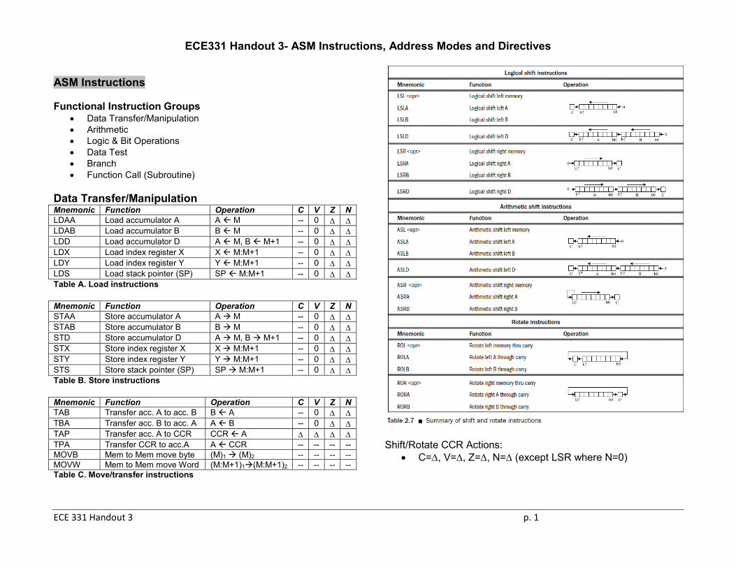
Data Transfer/Manipulation Mnemonic Function Operation C V Z N LDAA Load accumulator A A M -- 0 ∆ ∆ LDAB Load accumulator B B M -- 0 ∆ ∆ LDD Load accumulator D A M, B M+1 -- 0 ∆ ∆ LDX Load index register X X M:M+1 -- 0 ∆ ∆ LDY Load index register Y Y M:M+1 -- 0 ∆ ∆ LDS Load stack pointer (SP) SP M:M+1 -- 0 ∆ ∆ Table A. Load instructions Mnemonic Function Operation C V Z N STAA Store accumulator A A M -- 0 ∆ ∆ STAB Store accumulator B B M -- 0 ∆ ∆ STD Store accumulator D A M, B M+1 -- 0 ∆ ∆ STX Store index register X X M:M+1 -- 0 ∆ ∆ STY Store index register Y Y M:M+1 -- 0 ∆ ∆ STS Store stack pointer (SP) SP M:M+1 -- 0 ∆ ∆ Table B. Store instructions Mnemonic Function Operation C V Z N TAB Transfer acc. A to acc. B B A -- 0 ∆ ∆ TBA Transfer acc. B to acc. A A B -- 0 ∆ ∆ TAP Transfer acc. A to CCR CCR A ∆ ∆ ∆ ∆ TPA Transfer CCR to acc.A A CCR -- -- -- -- MOVB Mem to Mem move byte (M)1 (M)2 -- -- -- -- MOVW Mem to Mem move Word (M:M+1)1(M:M+1)2 -- -- -- -- Table C. Move/transfer instructions
Shift/Rotate CCR Actions:
• C=∆, V=∆, Z=∆, N=∆ (except LSR where N=0)
ECE 331 Handout 3 p. 2
Arithmetic Mnemon Function Operation H C V Z N ABA Add acc. A and acc. B A A+B ∆ ∆ ∆ ∆ ∆ ABX Add acc. B to index reg. X X B+X ∆ ∆ ∆ ∆ ∆ ABY Add acc. B to index reg. Y Y B+Y ∆ ∆ ∆ ∆ ∆ ADDA Add acc. A with memory A A+M ∆ ∆ ∆ ∆ ∆ ADDB Add acc. B with memory B B+M ∆ ∆ ∆ ∆ ∆ ADDD Add acc. D with memory D D+M:M+1 -- ∆ ∆ ∆ ∆ ADCA ADDA with carry A A+M+C ∆ ∆ ∆ ∆ ∆ ADCB ADDB with carry B B+M+C ∆ ∆ ∆ ∆ ∆ Table D. Addition instructions Mnemonic Function Operation C V Z N SBA Subtract acc. B from acc. A A A-B ∆ ∆ ∆ ∆ SUBA Subtract memory from acc. A A A-M ∆ ∆ ∆ ∆ SUBB Subtract memory from acc. B B B-M ∆ ∆ ∆ ∆ SUBD Subtract memory from acc. D D D-M:M+1 ∆ ∆ ∆ ∆ SBCA SUBA with borrow A A-M-C ∆ ∆ ∆ ∆ SBCB SUBB with borrow B B-M-C ∆ ∆ ∆ ∆ Table E. Subtraction instructions Mnemonic Function Operation C V Z N DEC Decrement memory by 1 M M-1 -- ∆ ∆ ∆ DECA Decrement A by 1 A A-1 -- ∆ ∆ ∆ DECB Decrement B by 1 B B-1 -- ∆ ∆ ∆ DES Decrement SP by 1 SP SP-1 -- -- ∆ -- DEX Decrement X by 1 X X-1 -- -- ∆ -- DEY Decrement Y by 1 Y Y-1 -- -- -- -- Table F. Decrement instructions Mnemonic Function Operation C V Z N INC Increment memory by 1 M M+1 -- ∆ ∆ ∆ INCA Increment A by 1 A A+1 -- ∆ ∆ ∆ INCB Increment B by 1 B B+1 -- ∆ ∆ ∆ INS Increment SP by 1 SP SP+1 -- -- ∆ -- INX Increment X by 1 X X+1 -- -- ∆ -- INY Increment Y by 1 Y Y+1 -- -- -- -- Table G. Increment instructions
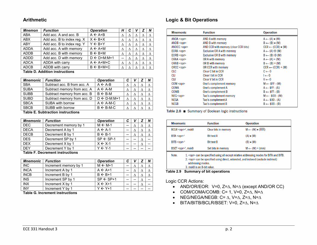
Logic & Bit Operations
Table 2.9 Summary of bit operations Logic CCR Actions:
• AND/OR/EOR: V=0, Z=∆, N=∆ (except AND/OR CC) • COM/COMA/COMB: C= 1, V=0, Z=∆, N=∆ • NEG/NEGA/NEGB: C= ∆, V=∆, Z=∆, N=∆ • BITA/BITB/BCLR/BSET: V=0, Z=∆, N=∆
ECE 331 Handout 3 p. 3
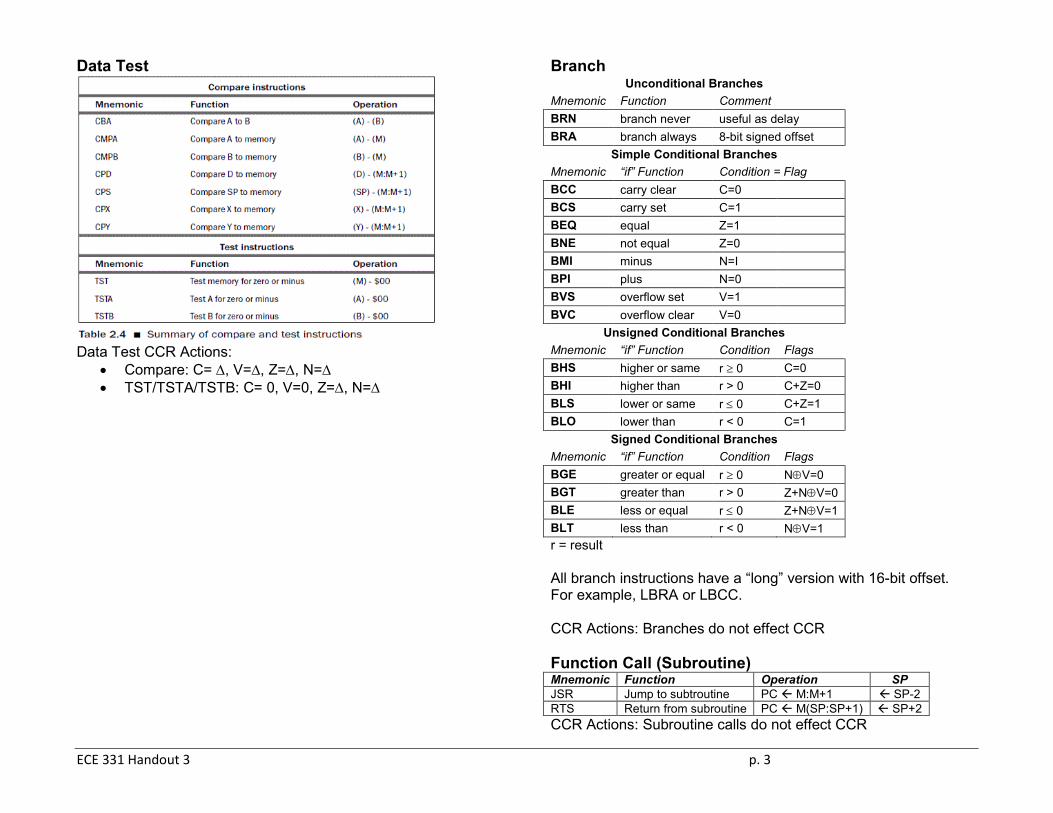
Data Test
Data Test CCR Actions:
• Compare: C= ∆, V=∆, Z=∆, N=∆ • TST/TSTA/TSTB: C= 0, V=0, Z=∆, N=∆
Branch Unconditional Branches
Mnemonic Function Comment BRN branch never useful as delay BRA branch always 8-bit signed offset
Simple Conditional Branches Mnemonic “if” Function Condition = Flag BCC carry clear C=0 BCS carry set C=1 BEQ equal Z=1 BNE not equal Z=0 BMI minus N=I BPI plus N=0 BVS overflow set V=1 BVC overflow clear V=0
Unsigned Conditional Branches Mnemonic “if” Function Condition Flags BHS higher or same r ≥ 0 C=0 BHI higher than r > 0 C+Z=0 BLS lower or same r ≤ 0 C+Z=1 BLO lower than r < 0 C=1
Signed Conditional Branches Mnemonic “if” Function Condition Flags BGE greater or equal r ≥ 0 N⊕V=0 BGT greater than r > 0 Z+N⊕V=0 BLE less or equal r ≤ 0 Z+N⊕V=1 BLT less than r < 0 N⊕V=1 r = result All branch instructions have a “long” version with 16-bit offset. For example, LBRA or LBCC. CCR Actions: Branches do not effect CCR Function Call (Subroutine) Mnemonic Function Operation SP JSR Jump to subtroutine PC M:M+1 SP-2 RTS Return from subroutine PC M(SP:SP+1) SP+2 CCR Actions: Subroutine calls do not effect CCR
ECE 331 Handout 3 p. 4
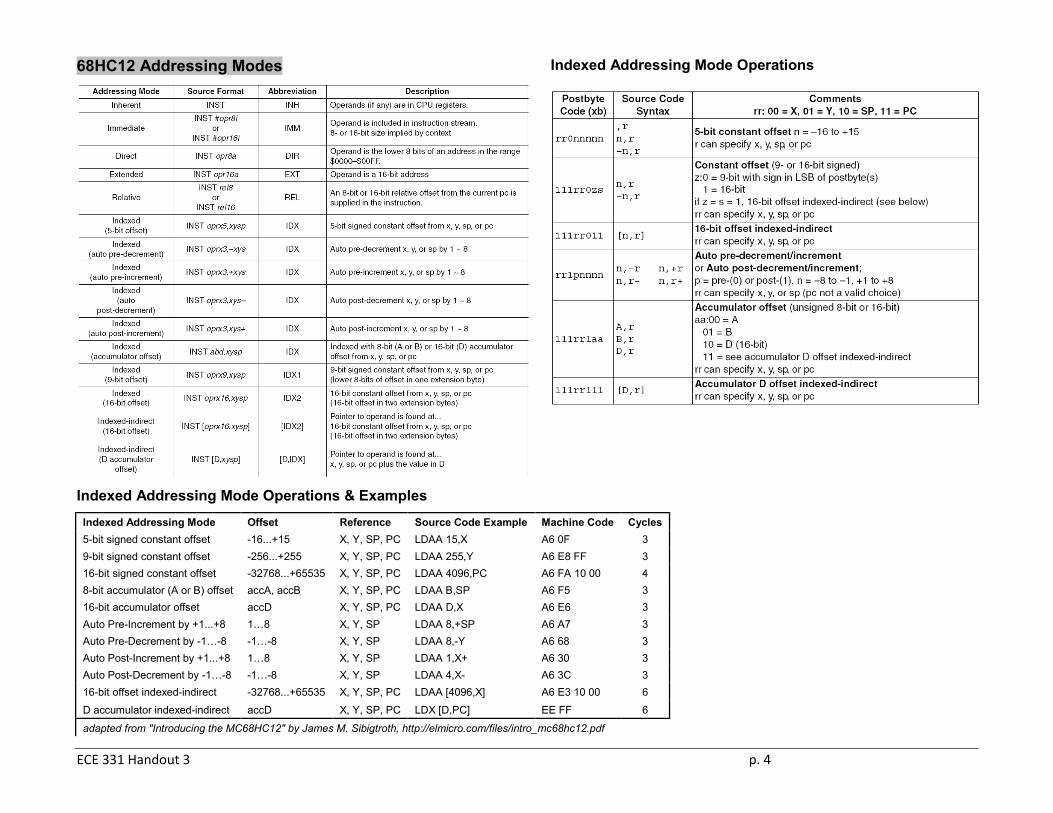
68HC12 Addressing Modes
Indexed Addressing Mode Operations
Indexed Addressing Mode Operations & Examples Indexed Addressing Mode Offset Reference Source Code Example Machine Code Cycles 5-bit signed constant offset -16...+15 X, Y, SP, PC LDAA 15,X A6 0F 3 9-bit signed constant offset -256...+255 X, Y, SP, PC LDAA 255,Y A6 E8 FF 3 16-bit signed constant offset -32768...+65535 X, Y, SP, PC LDAA 4096,PC A6 FA 10 00 4 8-bit accumulator (A or B) offset accA, accB X, Y, SP, PC LDAA B,SP A6 F5 3 16-bit accumulator offset accD X, Y, SP, PC LDAA D,X A6 E6 3 Auto Pre-Increment by +1...+8 1…8 X, Y, SP LDAA 8,+SP A6 A7 3 Auto Pre-Decrement by -1…-8 -1…-8 X, Y, SP LDAA 8,-Y A6 68 3 Auto Post-Increment by +1...+8 1…8 X, Y, SP LDAA 1,X+ A6 30 3 Auto Post-Decrement by -1…-8 -1…-8 X, Y, SP LDAA 4,X- A6 3C 3 16-bit offset indexed-indirect -32768...+65535 X, Y, SP, PC LDAA [4096,X] A6 E3 10 00 6
D accumulator indexed-indirect accD X, Y, SP, PC LDX [D,PC] EE FF 6
adapted from "Introducing the MC68HC12" by James M. Sibigtroth, http://elmicro.com/files/intro_mc68hc12.pdf

ECE 331 Handout 3 p. 5
HC12 ASM Directives
EQU equates symbol with numeric valve -use to define memory location or constant -assembler replaces label with correct # value EX: LIST EQU $5B defines variable ‘LIST’ = $5B
ORG origin: set memory address of instructions/data that follow -all programs must specific their ORG EX: TOP ORG $6000 sets program origin at $6000
END set end of program -any ASM instructions following END are ignored -can have directives after END
SWI software interrupt -stops program execution -use while testing/debugging code
RMB reserve block of memory EX: TEMP BMP $10 reserves 16 ($10) bytes starting at addr. assigned to label TEMP
FCB form constant byte -reserves block of memory & initiates contents of reserved block EX: ABC FCB $11, $12, $13 reserves 3 bytes w/ valves $11, $12 & $13 at addr. assigned to ABC
FDB form double-byte, same as FCB but 2 bytes per operand
FCC form constant character -stores ASCII code for alphanumeric characters enclosed in " " symbols EX: NAME FCC “MIKE” stores 4 ASCII bytes for MIKE
ECE 331 Handout 3 p. 6
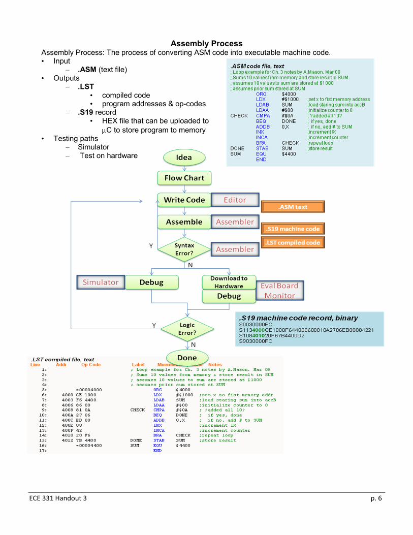
Assembly Process Assembly Process: The process of converting ASM code into executable machine code. • Input
– .ASM (text file) • Outputs
– .LST • compiled code • program addresses & op-codes
– .S19 record • HEX file that can be uploaded to
µC to store program to memory • Testing paths
– Simulator – Test on hardware
ECE 331 Handout 3 p. 7
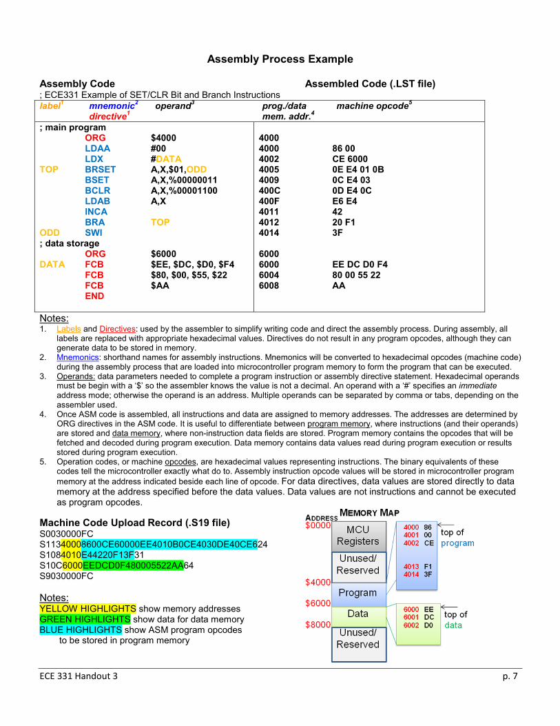
Assembly Process Example
Assembly Code Assembled Code (.LST file) ; ECE331 Example of SET/CLR Bit and Branch Instructions label1 mnemonic2 operand3 prog./data machine opcode5 directive1 mem. addr.4 ; main program ORG $4000 LDAA #00 LDX #DATA TOP BRSET A,X,$01,ODD BSET A,X,%00000011 BCLR A,X,%00001100 LDAB A,X INCA BRA TOP ODD SWI ; data storage ORG $6000 DATA FCB $EE, $DC, $D0, $F4 FCB $80, $00, $55, $22 FCB $AA END
4000 4000 86 00 4002 CE 6000 4005 0E E4 01 0B 4009 0C E4 03 400C 0D E4 0C 400F E6 E4 4011 42 4012 20 F1 4014 3F 6000 6000 EE DC D0 F4 6004 80 00 55 22 6008 AA
Notes: 1. Labels and Directives: used by the assembler to simplify writing code and direct the assembly process. During assembly, all
labels are replaced with appropriate hexadecimal values. Directives do not result in any program opcodes, although they can generate data to be stored in memory.
2. Mnemonics: shorthand names for assembly instructions. Mnemonics will be converted to hexadecimal opcodes (machine code) during the assembly process that are loaded into microcontroller program memory to form the program that can be executed.
3. Operands: data parameters needed to complete a program instruction or assembly directive statement. Hexadecimal operands must be begin with a ‘$’ so the assembler knows the value is not a decimal. An operand with a ‘#’ specifies an immediate address mode; otherwise the operand is an address. Multiple operands can be separated by comma or tabs, depending on the assembler used.
4. Once ASM code is assembled, all instructions and data are assigned to memory addresses. The addresses are determined by ORG directives in the ASM code. It is useful to differentiate between program memory, where instructions (and their operands) are stored and data memory, where non-instruction data fields are stored. Program memory contains the opcodes that will be fetched and decoded during program execution. Data memory contains data values read during program execution or results stored during program execution.
5. Operation codes, or machine opcodes, are hexadecimal values representing instructions. The binary equivalents of these codes tell the microcontroller exactly what do to. Assembly instruction opcode values will be stored in microcontroller program memory at the address indicated beside each line of opcode. For data directives, data values are stored directly to data memory at the address specified before the data values. Data values are not instructions and cannot be executed as program opcodes.
Machine Code Upload Record (.S19 file) S0030000FC S11340008600CE60000EE4010B0CE4030DE40CE624 S1084010E44220F13F31 S10C6000EEDCD0F480005522AA64 S9030000FC Notes: YELLOW HIGHLIGHTS show memory addresses GREEN HIGHLIGHTS show data for data memory BLUE HIGHLIGHTS show ASM program opcodes
to be stored in program memory