Embed Size (px)
Citation preview
ECE/CS 757: Advanced Computer Architecture II
Instructor:Mikko H Lipasti
Spring 2017
University of Wisconsin-Madison
Lecture notes based on slides created by John Shen, Mark Hill, David Wood, Guri Sohi, Jim Smith, Natalie
Enright Jerger, Michel Dubois, Murali Annavaram, Per Stenström and probably others
Lecture 3 Outline
• Multithreaded processors • Multicore processors
2 Mikko Lipasti-University of Wisconsin
Multithreaded Cores
• Basic idea: – CPU resources are expensive and should not be idle
• 1960’s: Virtual memory and multiprogramming – Virtual memory/multiprogramming invented to
tolerate latency to secondary storage (disk/tape/etc.) – Processor-disk speed mismatch:
• microseconds to tens of milliseconds (1:10000 or more)
– OS context switch used to bring in other useful work while waiting for page fault or explicit read/write
– Cost of context switch must be much less than I/O latency (easy)
3 Mikko Lipasti-University of Wisconsin
Multithreaded Cores
• 1990’s: Memory wall and multithreading – Processor-DRAM speed mismatch:
• nanosecond to fractions of a microsecond (1:500)
– H/W task switch used to bring in other useful work while waiting for cache miss
– Cost of context switch must be much less than cache miss latency
• Very attractive for applications with abundant thread-level parallelism – Commercial multi-user workloads
4 Mikko Lipasti-University of Wisconsin
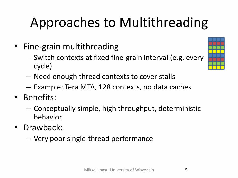
Approaches to Multithreading
• Fine-grain multithreading – Switch contexts at fixed fine-grain interval (e.g. every
cycle)
– Need enough thread contexts to cover stalls
– Example: Tera MTA, 128 contexts, no data caches
• Benefits: – Conceptually simple, high throughput, deterministic
behavior
• Drawback: – Very poor single-thread performance
5 Mikko Lipasti-University of Wisconsin

Approaches to Multithreading
• Coarse-grain multithreading
– Switch contexts on long-latency events (e.g. cache misses)
– Need a handful of contexts (2-4) for most benefit
• Example: IBM RS64-IV (Northstar), 2 contexts
• Benefits:
– Simple, improved throughput (~30%), low cost
– Thread priorities mostly avoid single-thread slowdown
• Drawback:
– Nondeterministic, conflicts in shared caches
6 Mikko Lipasti-University of Wisconsin
Approaches to Multithreading • Simultaneous multithreading
– Multiple concurrent active threads (no notion of thread switching)
– Need a handful of contexts for most benefit (2-8)
• Examples: Intel P4, Intel Nehalem, IBM Power 5/6/7/8, Alpha EV8/21464, AMD Zen
• Benefits: – Natural fit for OOO superscalar
– Improved throughput
– Low incremental cost
• Drawbacks: – Additional complexity over OOO superscalar
– Cache conflicts
7 Mikko Lipasti-University of Wisconsin
Approaches to Multithreading
• Chip Multithreading (CMT) – Similar to CMP
• Share something in the core: – Expensive resource, e.g. floating-point unit (FPU)
– Also share L2, system interconnect (memory and I/O bus)
• Example: Sun Niagara, 8 cores per die, one FPU • Benefits:
– Same as CMP
– Further: amortize cost of expensive resource over multiple cores
• Drawbacks: – Shared resource may become bottleneck
– 2nd generation (Niagara 2) does not share FPU
8 Mikko Lipasti-University of Wisconsin
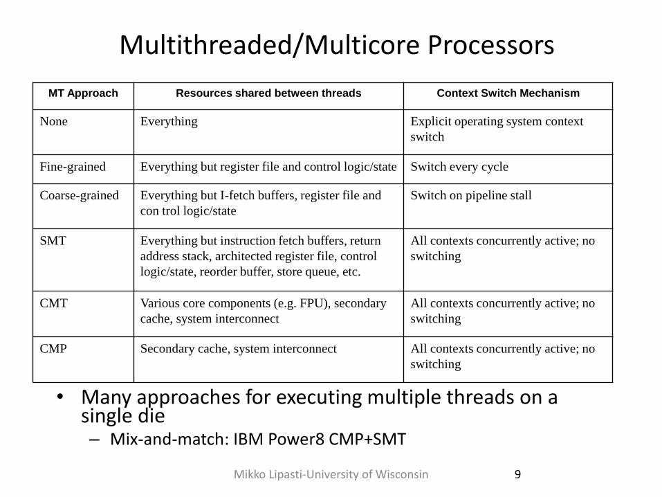
Multithreaded/Multicore Processors
• Many approaches for executing multiple threads on a single die – Mix-and-match: IBM Power8 CMP+SMT
MT Approach Resources shared between threads Context Switch Mechanism
None Everything Explicit operating system context
switch
Fine-grained Everything but register file and control logic/state Switch every cycle
Coarse-grained Everything but I-fetch buffers, register file and
con trol logic/state
Switch on pipeline stall
SMT Everything but instruction fetch buffers, return
address stack, architected register file, control
logic/state, reorder buffer, store queue, etc.
All contexts concurrently active; no
switching
CMT Various core components (e.g. FPU), secondary
cache, system interconnect
All contexts concurrently active; no
switching
CMP Secondary cache, system interconnect All contexts concurrently active; no
switching
9 Mikko Lipasti-University of Wisconsin
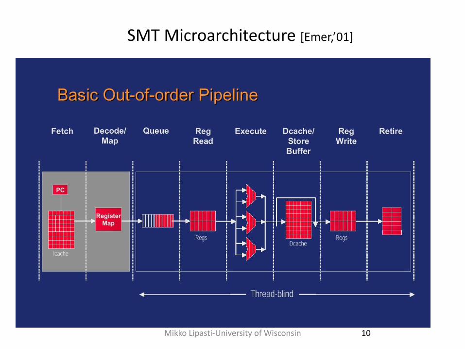
SMT Microarchitecture [Emer,’01]
10 Mikko Lipasti-University of Wisconsin
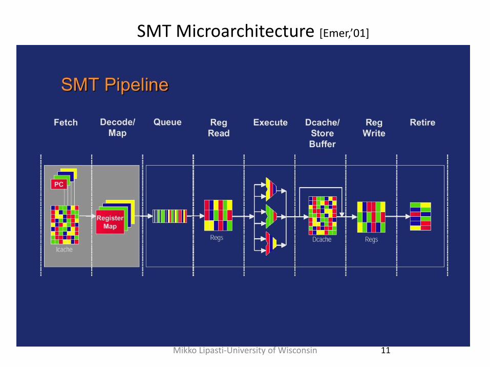
SMT Microarchitecture [Emer,’01]
11 Mikko Lipasti-University of Wisconsin
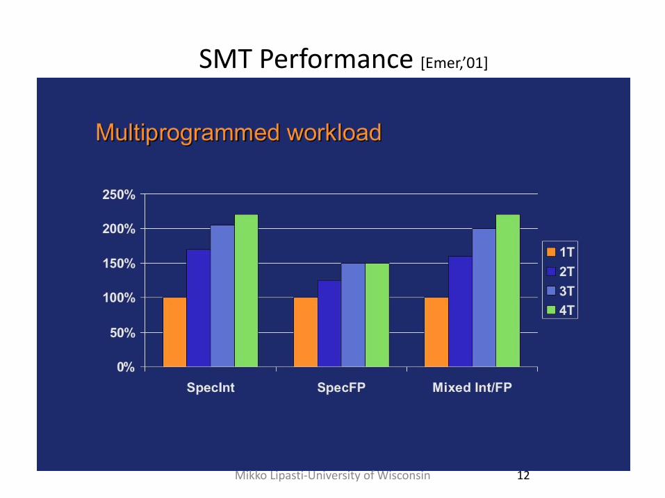
SMT Performance [Emer,’01]
12 Mikko Lipasti-University of Wisconsin
Mikko Lipasti-University of Wisconsin 13
Historical Multithreaded Processors
• CDC6600 PPs
– I/O processing
• Denelcor HEP
– General purpose scientific
Mikko Lipasti-University of Wisconsin 14
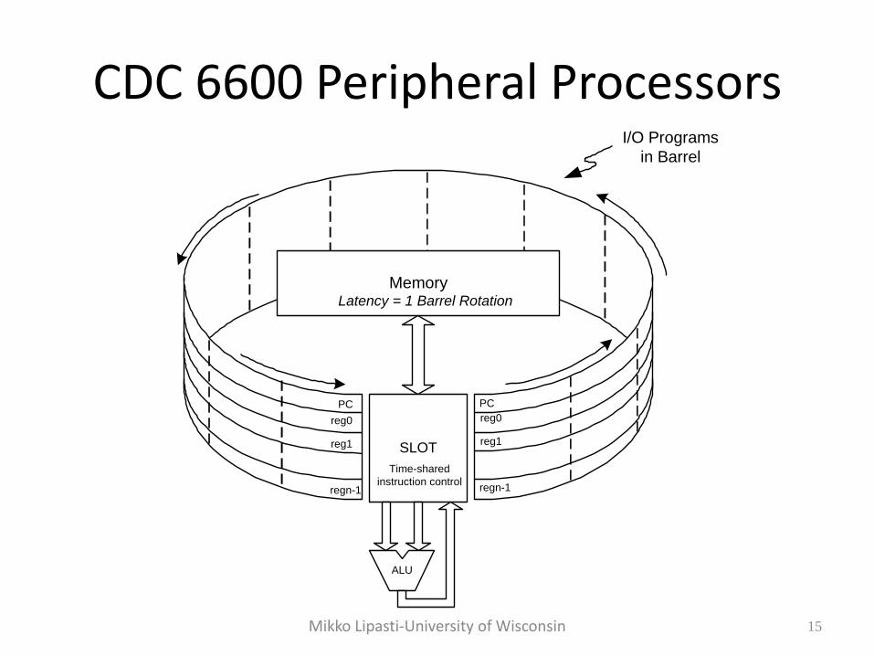
CDC 6600 Peripheral Processors • Intended to perform OS and I/O functions
• Used "barrel and slot"
– register state is arranged around a “barrel”
– one set of ALU and memory hardware accessed through “slot” in barrel
– slot in barrel rotates one position each cycle
• Could be used as stand-alone "MP"
• Similar method later used in IBM Channels
Mikko Lipasti-University of Wisconsin 15
CDC 6600 Peripheral Processors
SLOT
PC
reg0
reg1
regn-1
PC
reg0
reg1
regn-1
Time-shared
instruction control
Memory
ALU
I/O Programs
in Barrel
Latency = 1 Barrel Rotation
Mikko Lipasti-University of Wisconsin 16
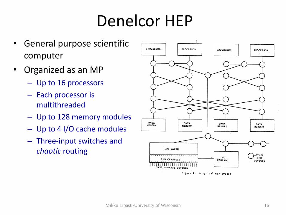
Denelcor HEP • General purpose scientific
computer
• Organized as an MP
– Up to 16 processors
– Each processor is multithreaded
– Up to 128 memory modules
– Up to 4 I/O cache modules
– Three-input switches and chaotic routing
Mikko Lipasti-University of Wisconsin 17
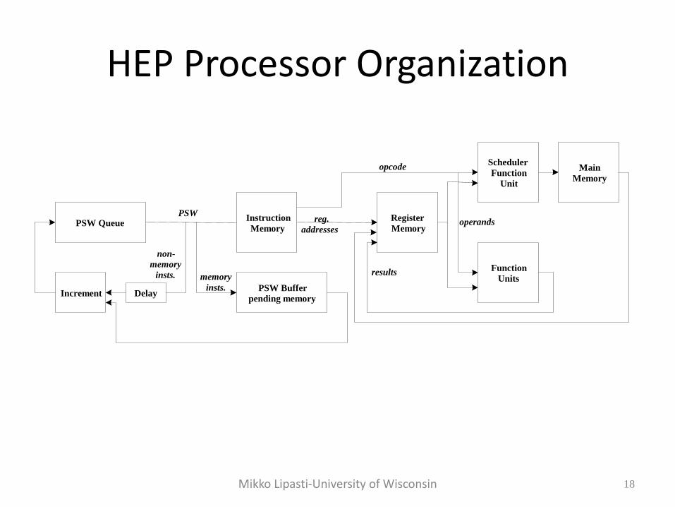
HEP Processor Organization • Multiple contexts (threads) are supported;
– 120 threads
– Each with a PSW (program status word)
• PSWs circulate in a control loop
– control and data loops pipelined 8 deep
– PSW in control loop can circulate no faster than data in data loop
– PSW at queue head fetches and starts execution of next instruction
– No inter-instruction pipeline forwarding or stalls needed
• Clock period: 100 ns
– 8 PSWs in control loop => 10 MIPS
– Maximum perf. per thread => 1.25 MIPS
(They tried to sell this as a supercomputer)
Mikko Lipasti-University of Wisconsin 18
HEP Processor Organization
PSW Queue Instruction
Memory
Register
Memory
Function
Units
Scheduler
Function
Unit
Main
Memory
PSW Buffer
pending memory Increment Delay
PSW
memory
insts.
non-
memory
insts.
opcode
reg.
addresses operands
results
Mikko Lipasti-University of Wisconsin 19
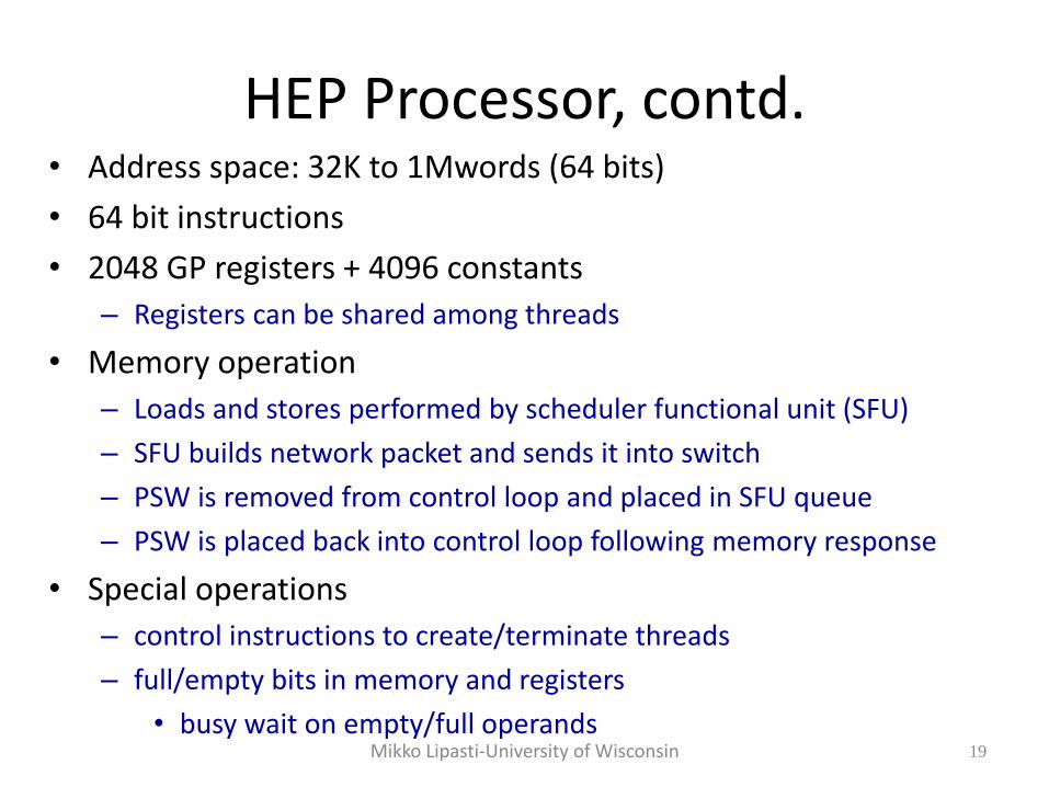
HEP Processor, contd. • Address space: 32K to 1Mwords (64 bits)
• 64 bit instructions
• 2048 GP registers + 4096 constants
– Registers can be shared among threads
• Memory operation
– Loads and stores performed by scheduler functional unit (SFU)
– SFU builds network packet and sends it into switch
– PSW is removed from control loop and placed in SFU queue
– PSW is placed back into control loop following memory response
• Special operations
– control instructions to create/terminate threads
– full/empty bits in memory and registers
• busy wait on empty/full operands
Mikko Lipasti-University of Wisconsin 20
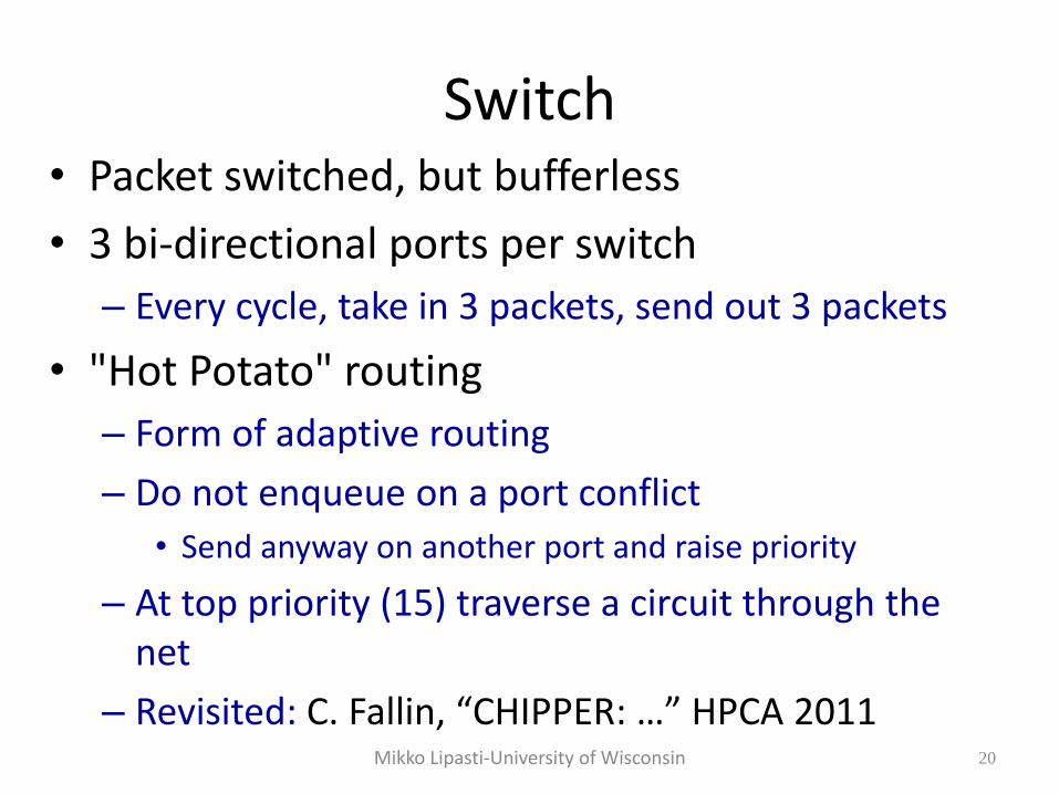
Switch • Packet switched, but bufferless
• 3 bi-directional ports per switch
– Every cycle, take in 3 packets, send out 3 packets
• "Hot Potato" routing
– Form of adaptive routing
– Do not enqueue on a port conflict
• Send anyway on another port and raise priority
– At top priority (15) traverse a circuit through the net
– Revisited: C. Fallin, “CHIPPER: …” HPCA 2011
Mikko Lipasti-University of Wisconsin 21
Modern Day Multi-Threading • Apply to superscalar pipelines
– More resources to share
• Also one-wide in-order processors
– Provide high efficiency for throughput-oriented servers
• Start with case study
– Intel Pentium 4 Hyperthreading D. Marr et al. Hyper-Threading Technology Architecture and Microarchitecture. Intel Technology Journal, Feb. 2002
© J.E. Smith 22
Intel Hyperthreading • Part of Pentium 4 design (Xeon)
• Two threads per processor
• Goals
– Low cost – less than 5% overhead for replicated state
– Assure forward progress of both threads
• Make sure both threads get some buffer resources
• through partitioning or budgeting
– Single thread running alone does not suffer slowdown
© J.E. Smith 23
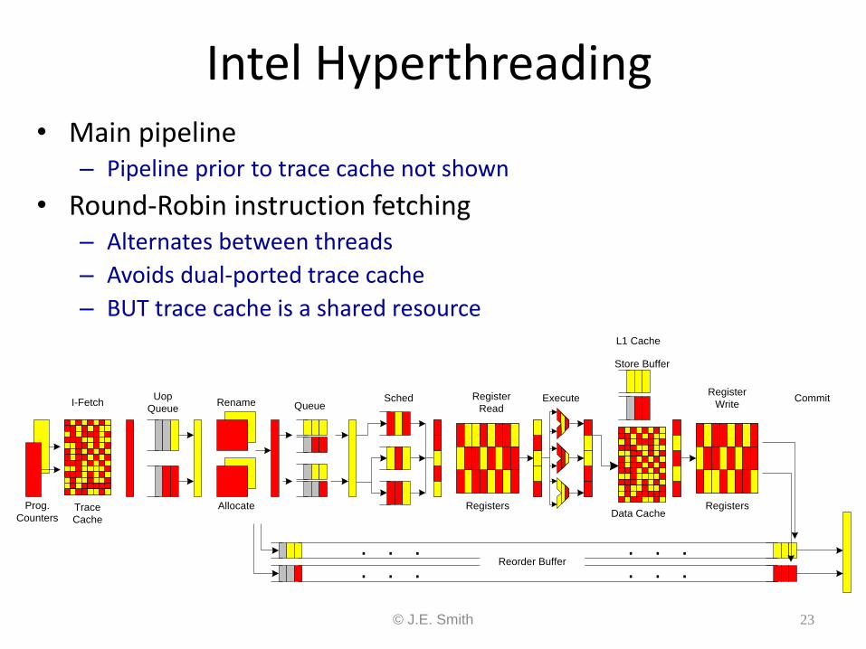
Intel Hyperthreading • Main pipeline
– Pipeline prior to trace cache not shown
• Round-Robin instruction fetching – Alternates between threads
– Avoids dual-ported trace cache
– BUT trace cache is a shared resource
Uop
QueueRename
Allocate
QueueSched Register
Read
Registers
Execute
L1 Cache
Data Cache
Store Buffer
Register
Write
Registers
Commit
. . . . . .
. . . . . .Reorder Buffer
I-Fetch
Trace
Cache
Prog.
Counters
Mikko Lipasti-University of Wisconsin 24
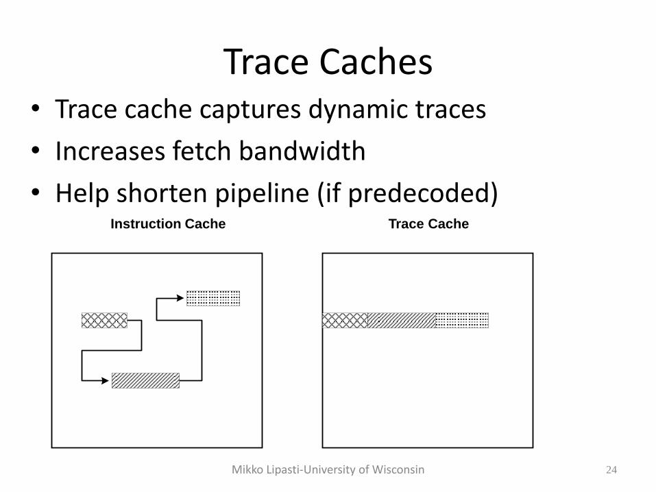
Trace Caches • Trace cache captures dynamic traces
• Increases fetch bandwidth
• Help shorten pipeline (if predecoded) Instruction Cache Trace Cache
© J.E. Smith 25
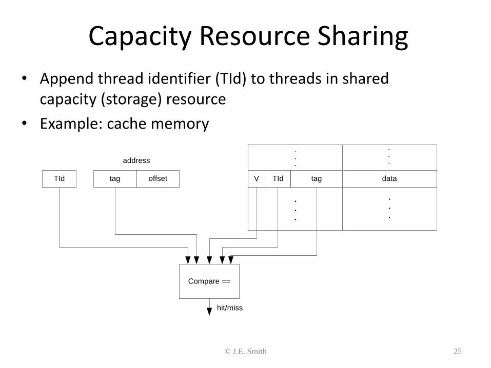
Capacity Resource Sharing
• Append thread identifier (TId) to threads in shared capacity (storage) resource
• Example: cache memory
TId TId tag dataVtag offset
address
Compare ==
.
.
.
.
.
.
.
.
.
.
.
.
hit/miss
© J.E. Smith 26
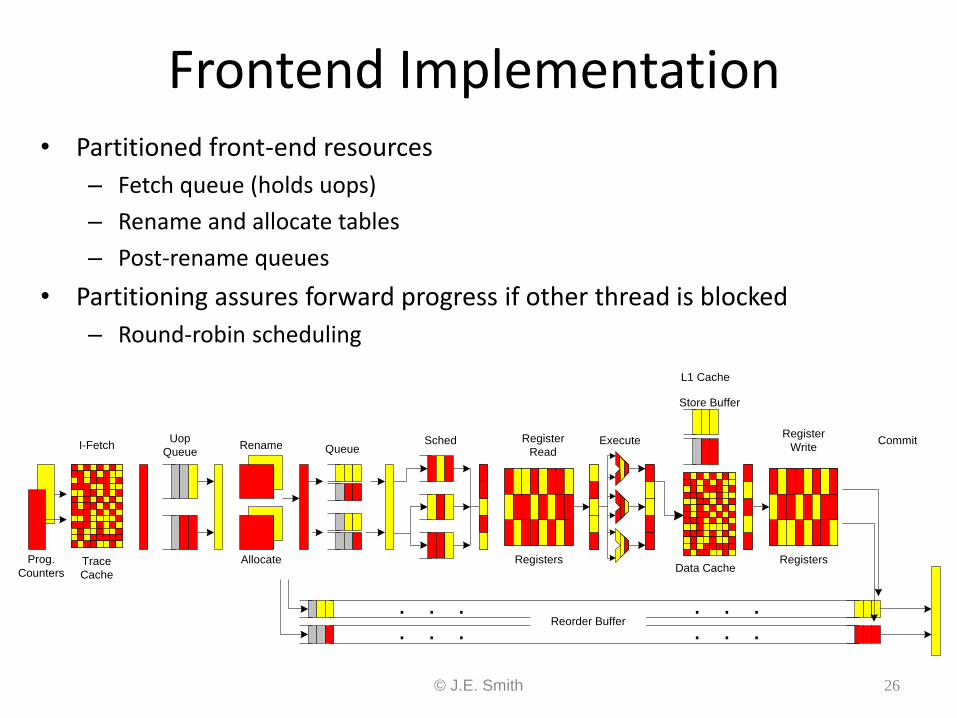
Frontend Implementation • Partitioned front-end resources
– Fetch queue (holds uops)
– Rename and allocate tables
– Post-rename queues
• Partitioning assures forward progress if other thread is blocked
– Round-robin scheduling
Uop
QueueRename
Allocate
QueueSched Register
Read
Registers
Execute
L1 Cache
Data Cache
Store Buffer
Register
Write
Registers
Commit
. . . . . .
. . . . . .Reorder Buffer
I-Fetch
Trace
Cache
Prog.
Counters
© J.E. Smith 27
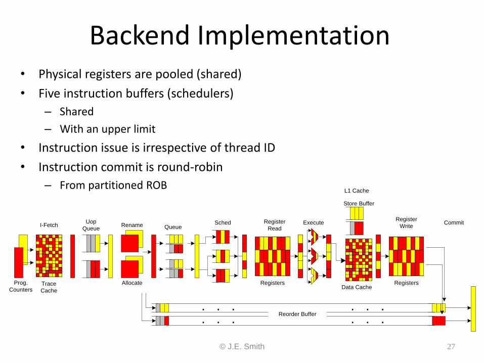
Backend Implementation
Uop
QueueRename
Allocate
QueueSched Register
Read
Registers
Execute
L1 Cache
Data Cache
Store Buffer
Register
Write
Registers
Commit
. . . . . .
. . . . . .Reorder Buffer
I-Fetch
Trace
Cache
Prog.
Counters
• Physical registers are pooled (shared)
• Five instruction buffers (schedulers)
– Shared
– With an upper limit
• Instruction issue is irrespective of thread ID
• Instruction commit is round-robin
– From partitioned ROB
© J.E. Smith 28
Operating Modes and OS Support • MT-mode – two active logical processors; shared/partitioned
resources
• ST-mode (ST0 or ST1) – one logical processor; combined resources
• HALT – privileged instruction => (normally) low power mode – IN MT mode => transition to ST0 or ST1
(depending on the thread that HALTed)
– In ST mode => low power mode
• Interrupt to HALTed thread => transition to MT mode
• OS manages two “processors” – OS code should HALT rather than idle loop
– Schedule threads with priority to ST mode
• (require OS knowledge of hyperthreading)
© J.E. Smith 29
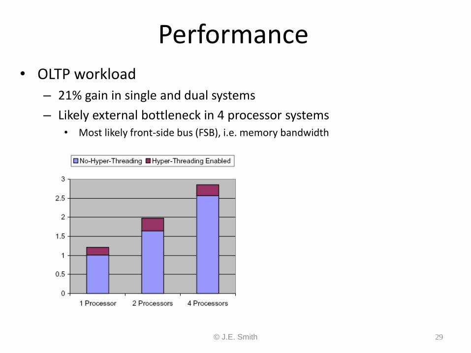
Performance • OLTP workload
– 21% gain in single and dual systems
– Likely external bottleneck in 4 processor systems • Most likely front-side bus (FSB), i.e. memory bandwidth
© J.E. Smith 30
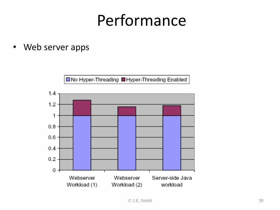
Performance
• Web server apps
© J.E. Smith 31
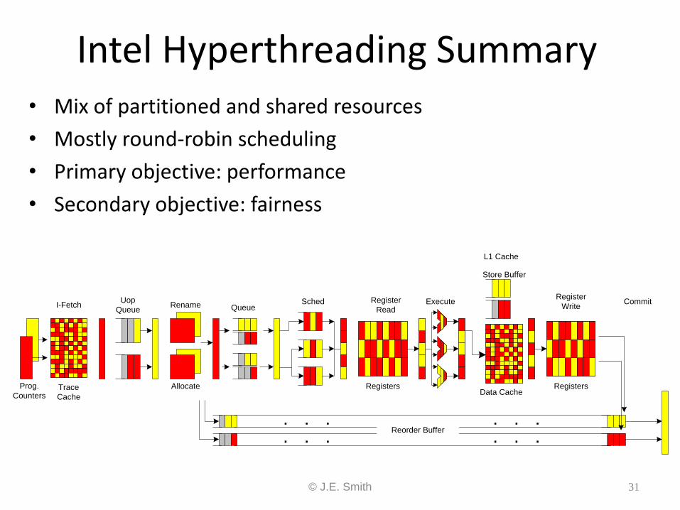
Intel Hyperthreading Summary • Mix of partitioned and shared resources
• Mostly round-robin scheduling
• Primary objective: performance
• Secondary objective: fairness
Uop
QueueRename
Allocate
QueueSched Register
Read
Registers
Execute
L1 Cache
Data Cache
Store Buffer
Register
Write
Registers
Commit
. . . . . .
. . . . . .Reorder Buffer
I-Fetch
Trace
Cache
Prog.
Counters
© J.E. Smith 32
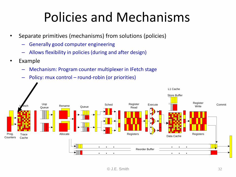
Policies and Mechanisms • Separate primitives (mechanisms) from solutions (policies)
– Generally good computer engineering
– Allows flexibility in policies (during and after design)
• Example
– Mechanism: Program counter multiplexer in IFetch stage
– Policy: mux control – round-robin (or priorities)
Uop
QueueRename
Allocate
QueueSched Register
Read
Registers
Execute
L1 Cache
Data Cache
Store Buffer
Register
Write
Registers
Commit
. . . . . .
. . . . . .Reorder Buffer
I-Fetch
Trace
Cache
Prog.
Counters
© J.E. Smith 33
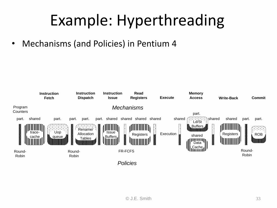
Example: Hyperthreading • Mechanisms (and Policies) in Pentium 4
part. part. part.part. part. shared shared
Registers
shared shared shared
Execution
Data
Cache
part.
shared Registers
sharedshared
Mechanisms
Policies
part.
Round-
Robin
FR-FCFS Round-
Robin
shared
Program
Counters
Instruction
Fetch
Instruction
Dispatch
Instruction
Issue
Read
Registers ExecuteMemory
Access Write-Back Commit
trace-
cache
Uop
queue
Rename/
Allocation
Tables
Ld/St
Buffers
Issue
BuffersRegisters
Data
Cache
Registers ROB
Round-
Robin
part.
© J.E. Smith 34
Dispatch Policy • Primary point for resource management
• Intel design uses software-settable priorities
– Set via software writeable control register
– Application software can control some of the priority settings
– Priority 0 => idle, priority 1 => spinning
– Both threads at level 1 => throttle to save power
• Hardware feedback can adjust priorities
• Reference:
– D.M. Tullsen et al., ”Exploiting choice:…” ISCA 1996.
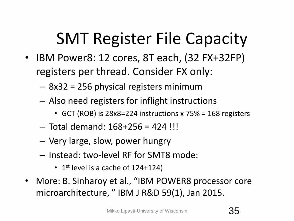
SMT Register File Capacity • IBM Power8: 12 cores, 8T each, (32 FX+32FP)
registers per thread. Consider FX only:
– 8x32 = 256 physical registers minimum
– Also need registers for inflight instructions • GCT (ROB) is 28x8=224 instructions x 75% = 168 registers
– Total demand: 168+256 = 424 !!!
– Very large, slow, power hungry
– Instead: two-level RF for SMT8 mode: • 1st level is a cache of 124+124)
• More: B. Sinharoy et al., “IBM POWER8 processor core microarchitecture, ” IBM J R&D 59(1), Jan 2015.
Mikko Lipasti-University of Wisconsin 35
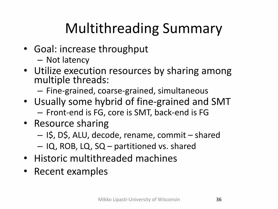
Multithreading Summary • Goal: increase throughput
– Not latency • Utilize execution resources by sharing among
multiple threads: – Fine-grained, coarse-grained, simultaneous
• Usually some hybrid of fine-grained and SMT – Front-end is FG, core is SMT, back-end is FG
• Resource sharing – I$, D$, ALU, decode, rename, commit – shared – IQ, ROB, LQ, SQ – partitioned vs. shared
• Historic multithreaded machines • Recent examples
36 Mikko Lipasti-University of Wisconsin
Lecture 3 Outline
• Multithreaded processors • Multicore processors
37 Mikko Lipasti-University of Wisconsin
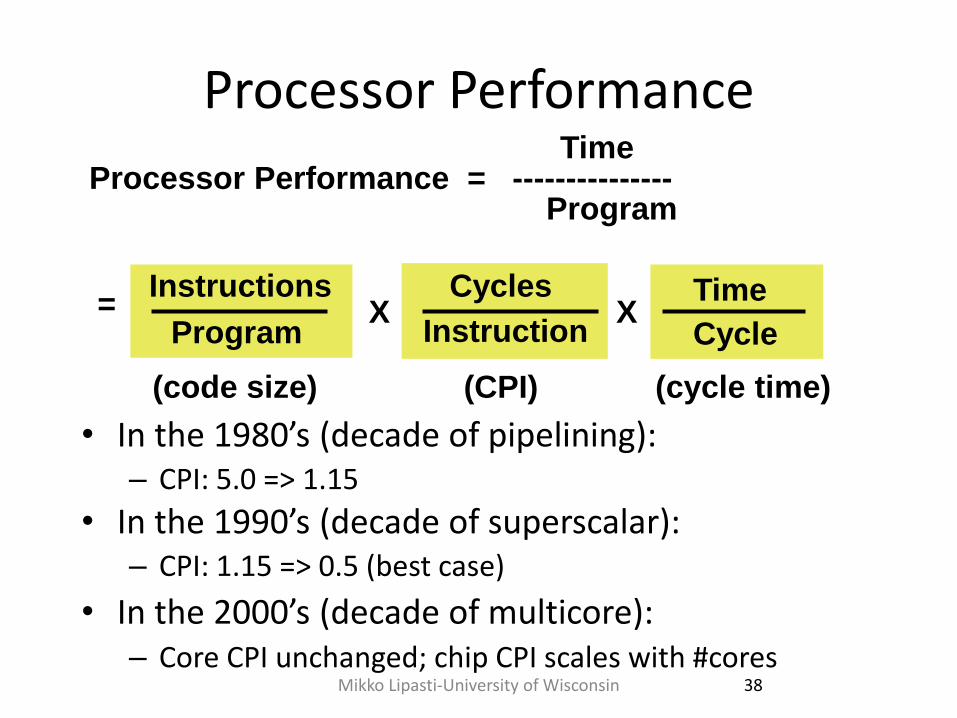
Processor Performance
• In the 1980’s (decade of pipelining): – CPI: 5.0 => 1.15
• In the 1990’s (decade of superscalar): – CPI: 1.15 => 0.5 (best case)
• In the 2000’s (decade of multicore): – Core CPI unchanged; chip CPI scales with #cores
Processor Performance = --------------- Time
Program
Instructions Cycles
Program Instruction
Time
Cycle
(code size)
= X X
(CPI) (cycle time)
38 Mikko Lipasti-University of Wisconsin
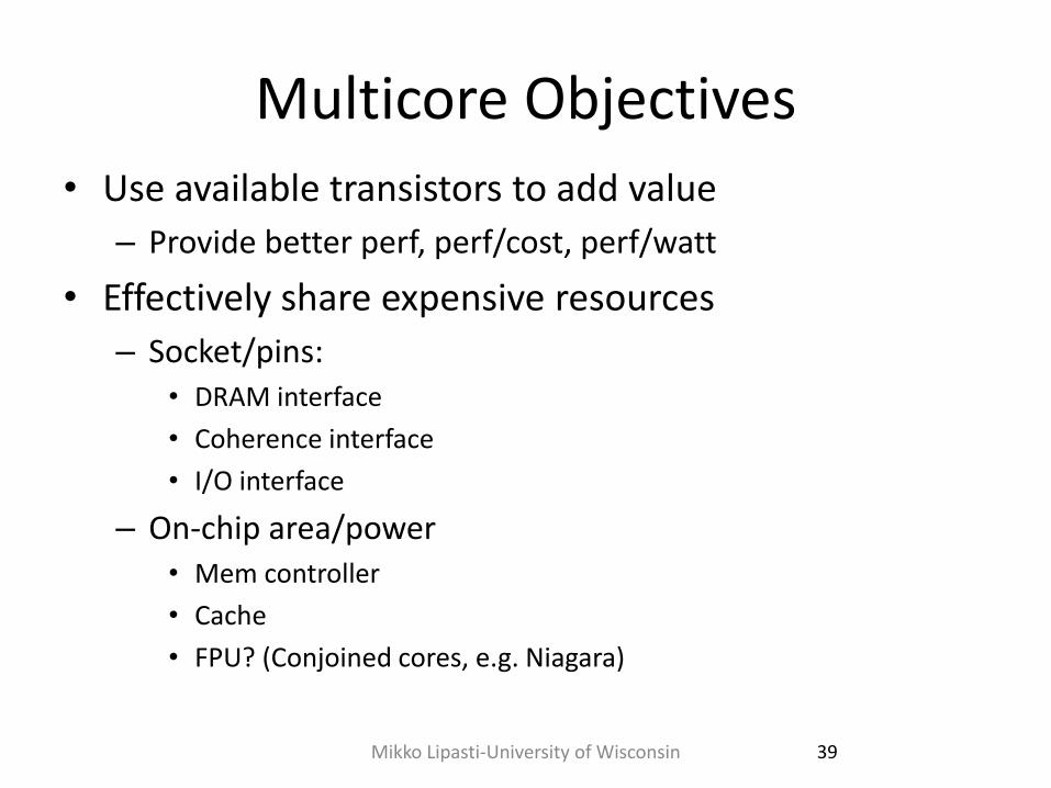
Multicore Objectives
• Use available transistors to add value
– Provide better perf, perf/cost, perf/watt
• Effectively share expensive resources
– Socket/pins: • DRAM interface
• Coherence interface
• I/O interface
– On-chip area/power • Mem controller
• Cache
• FPU? (Conjoined cores, e.g. Niagara)
39 Mikko Lipasti-University of Wisconsin
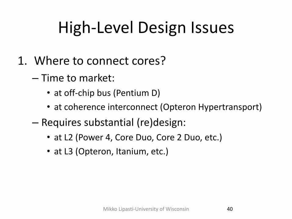
High-Level Design Issues
1. Where to connect cores?
– Time to market:
• at off-chip bus (Pentium D)
• at coherence interconnect (Opteron Hypertransport)
– Requires substantial (re)design:
• at L2 (Power 4, Core Duo, Core 2 Duo, etc.)
• at L3 (Opteron, Itanium, etc.)
40 Mikko Lipasti-University of Wisconsin
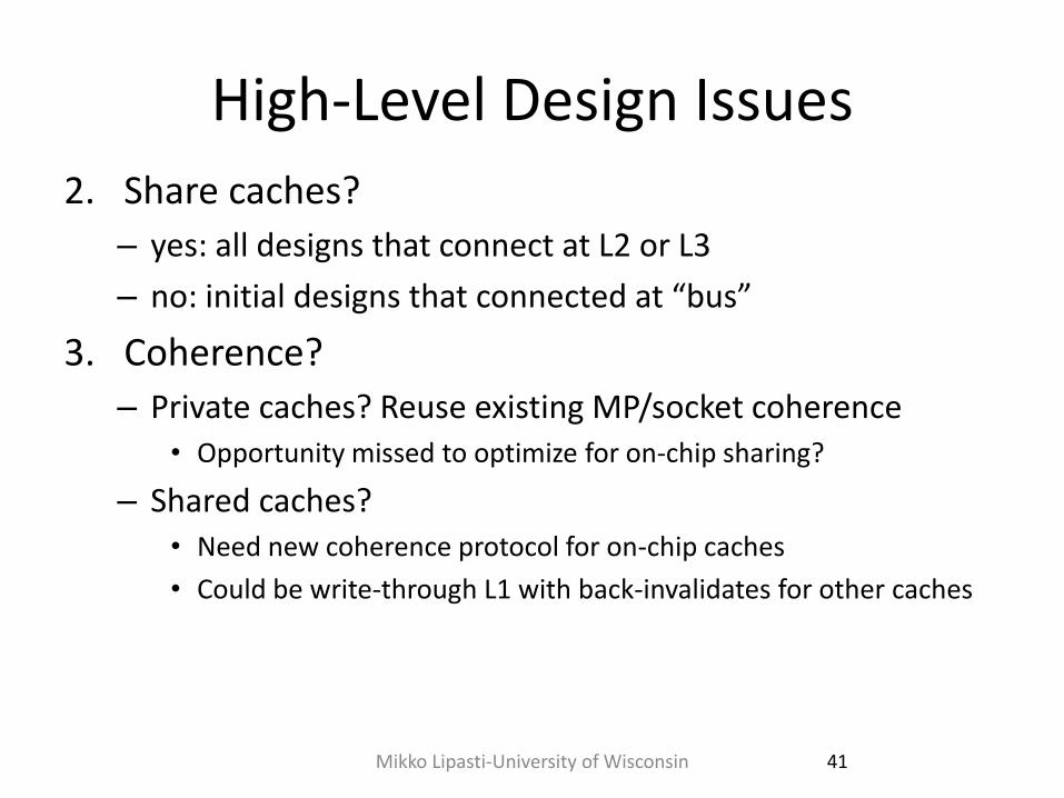
High-Level Design Issues
2. Share caches?
– yes: all designs that connect at L2 or L3
– no: initial designs that connected at “bus”
3. Coherence?
– Private caches? Reuse existing MP/socket coherence • Opportunity missed to optimize for on-chip sharing?
– Shared caches? • Need new coherence protocol for on-chip caches
• Could be write-through L1 with back-invalidates for other caches
41 Mikko Lipasti-University of Wisconsin
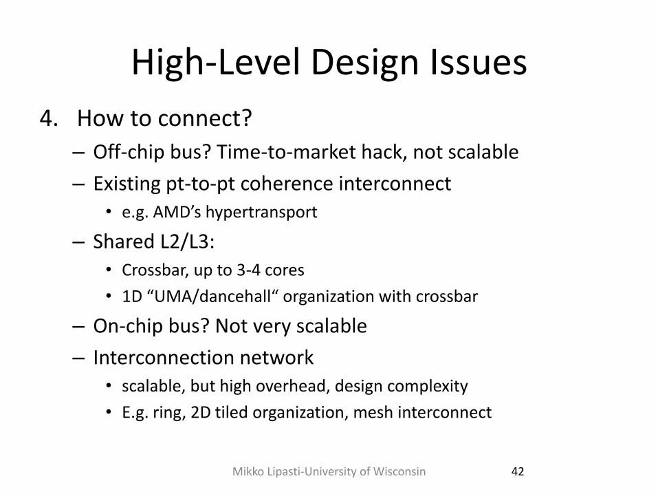
High-Level Design Issues
4. How to connect?
– Off-chip bus? Time-to-market hack, not scalable
– Existing pt-to-pt coherence interconnect • e.g. AMD’s hypertransport
– Shared L2/L3: • Crossbar, up to 3-4 cores
• 1D “UMA/dancehall“ organization with crossbar
– On-chip bus? Not very scalable
– Interconnection network • scalable, but high overhead, design complexity
• E.g. ring, 2D tiled organization, mesh interconnect
42 Mikko Lipasti-University of Wisconsin
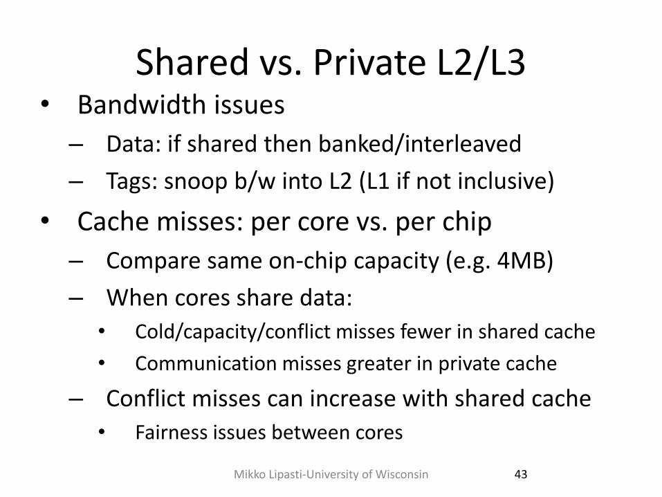
Shared vs. Private L2/L3 • Bandwidth issues
– Data: if shared then banked/interleaved
– Tags: snoop b/w into L2 (L1 if not inclusive)
• Cache misses: per core vs. per chip
– Compare same on-chip capacity (e.g. 4MB)
– When cores share data:
• Cold/capacity/conflict misses fewer in shared cache
• Communication misses greater in private cache
– Conflict misses can increase with shared cache
• Fairness issues between cores
43 Mikko Lipasti-University of Wisconsin
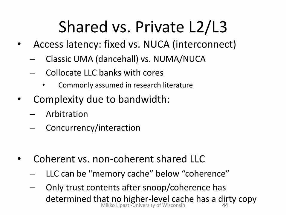
Shared vs. Private L2/L3 • Access latency: fixed vs. NUCA (interconnect)
– Classic UMA (dancehall) vs. NUMA/NUCA
– Collocate LLC banks with cores • Commonly assumed in research literature
• Complexity due to bandwidth:
– Arbitration
– Concurrency/interaction
• Coherent vs. non-coherent shared LLC
– LLC can be "memory cache” below “coherence”
– Only trust contents after snoop/coherence has determined that no higher-level cache has a dirty copy
44 Mikko Lipasti-University of Wisconsin
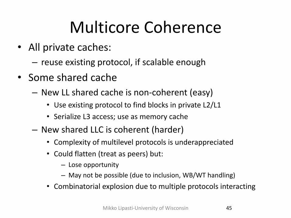
Multicore Coherence • All private caches:
– reuse existing protocol, if scalable enough
• Some shared cache
– New LL shared cache is non-coherent (easy) • Use existing protocol to find blocks in private L2/L1
• Serialize L3 access; use as memory cache
– New shared LLC is coherent (harder) • Complexity of multilevel protocols is underappreciated
• Could flatten (treat as peers) but:
– Lose opportunity
– May not be possible (due to inclusion, WB/WT handling)
• Combinatorial explosion due to multiple protocols interacting
45 Mikko Lipasti-University of Wisconsin
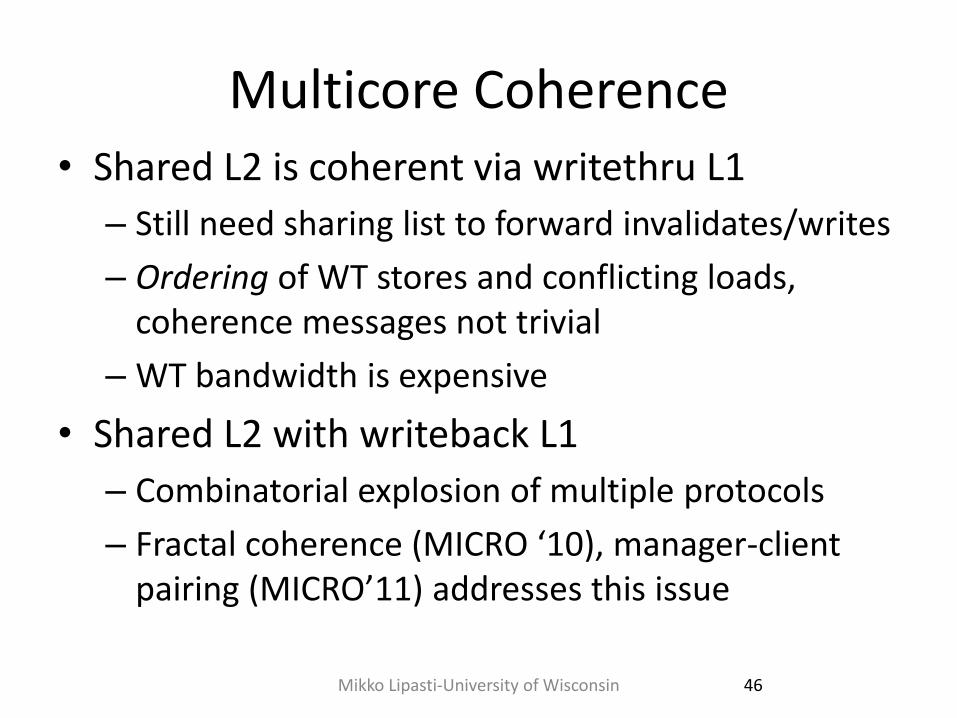
Multicore Coherence • Shared L2 is coherent via writethru L1
– Still need sharing list to forward invalidates/writes
– Ordering of WT stores and conflicting loads, coherence messages not trivial
– WT bandwidth is expensive
• Shared L2 with writeback L1
– Combinatorial explosion of multiple protocols
– Fractal coherence (MICRO ‘10), manager-client pairing (MICRO’11) addresses this issue
46 Mikko Lipasti-University of Wisconsin
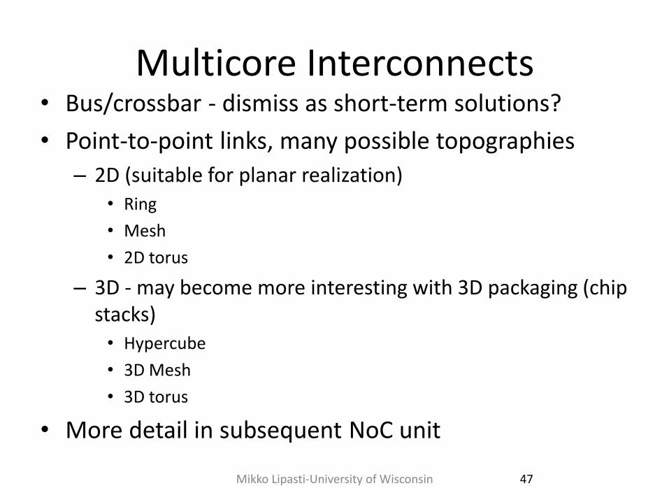
Multicore Interconnects • Bus/crossbar - dismiss as short-term solutions?
• Point-to-point links, many possible topographies
– 2D (suitable for planar realization) • Ring
• Mesh
• 2D torus
– 3D - may become more interesting with 3D packaging (chip stacks) • Hypercube
• 3D Mesh
• 3D torus
• More detail in subsequent NoC unit
47 Mikko Lipasti-University of Wisconsin
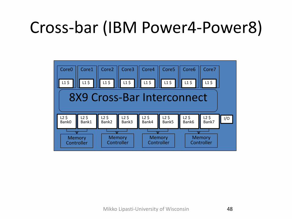
Cross-bar (IBM Power4-Power8)
Mikko Lipasti-University of Wisconsin 48
L1 $
Core0
L1 $
Core1
L1 $
Core2
L1 $
Core3
L1 $
Core4
L1 $
Core5
L1 $
Core6
L1 $
Core7
L2 $ Bank0
L2 $ Bank1
L2 $ Bank2
L2 $ Bank3
L2 $ Bank4
L2 $ Bank5
L2 $ Bank6
L2 $ Bank7
8X9 Cross-Bar Interconnect
Memory Controller
Memory Controller
Memory Controller
Memory Controller
I/O
On-Chip Bus/Crossbar • Used widely (Power4/5/6/7/8, Piranha, Niagara, etc.)
– Assumed not scalable
– Is this really true, given on-chip characteristics?
– Scales "far enough" : watch out for arguments at the limit
– e.g. swizzle-switch makes x-bar scalable enough [UMich]
• Simple, straightforward, nice ordering properties
– Wiring can be a nightmare (for crossbar)
– Bus bandwidth is weak (even multiple busses)
– Compare DEC Piranha 8-lane bus (32GB/s) to Power4 crossbar (100+GB/s)
– Workload BW demands: commercial vs. scientific
49 Mikko Lipasti-University of Wisconsin
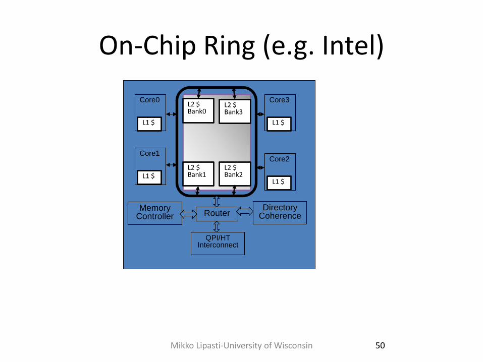
On-Chip Ring (e.g. Intel)
Mikko Lipasti-University of Wisconsin 50
L1 $
Core0
L1 $
Core1
L1 $
Core2
L1 $
Core3 L2 $ Bank0
L2 $ Bank1
L2 $ Bank2
L2 $ Bank3
Router Directory
Coherence
QPI/HT Interconnect
Memory Controller
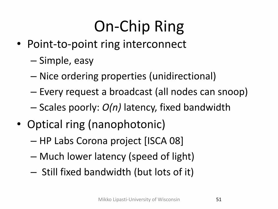
On-Chip Ring • Point-to-point ring interconnect
– Simple, easy
– Nice ordering properties (unidirectional)
– Every request a broadcast (all nodes can snoop)
– Scales poorly: O(n) latency, fixed bandwidth
• Optical ring (nanophotonic)
– HP Labs Corona project [ISCA 08]
– Much lower latency (speed of light)
– Still fixed bandwidth (but lots of it)
51 Mikko Lipasti-University of Wisconsin
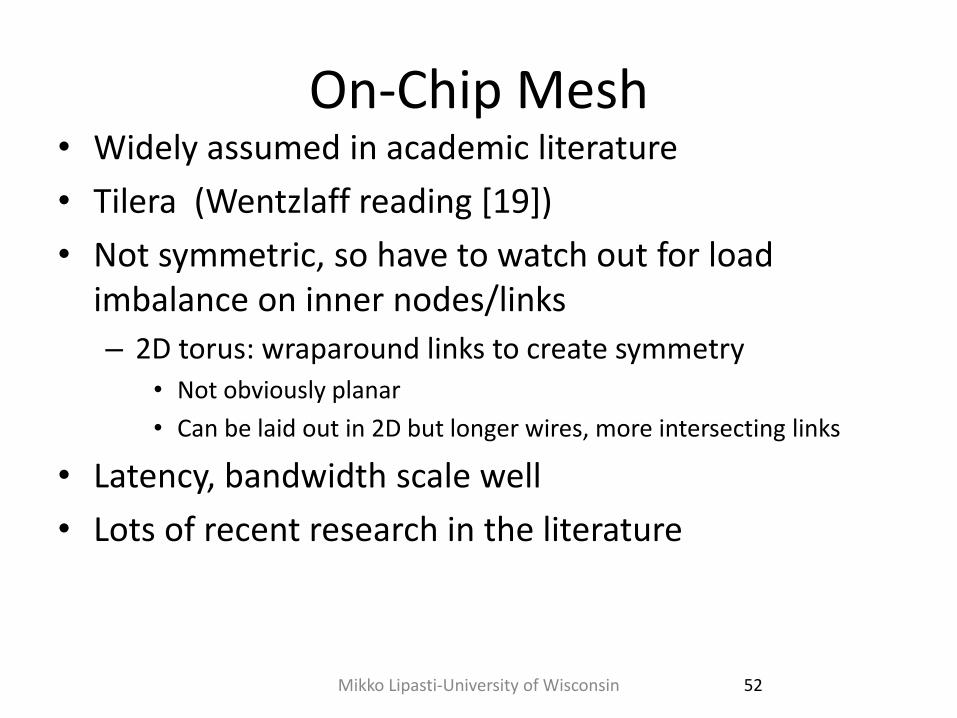
On-Chip Mesh • Widely assumed in academic literature
• Tilera (Wentzlaff reading [19])
• Not symmetric, so have to watch out for load imbalance on inner nodes/links
– 2D torus: wraparound links to create symmetry • Not obviously planar
• Can be laid out in 2D but longer wires, more intersecting links
• Latency, bandwidth scale well
• Lots of recent research in the literature
52 Mikko Lipasti-University of Wisconsin
Mikko Lipasti-University of Wisconsin 53
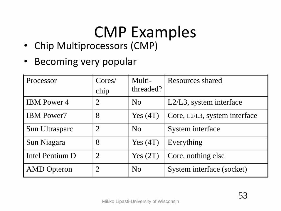
CMP Examples • Chip Multiprocessors (CMP)
• Becoming very popular
Processor Cores/
chip
Multi-threaded?
Resources shared
IBM Power 4 2 No L2/L3, system interface
IBM Power7 8 Yes (4T) Core, L2/L3, system interface
Sun Ultrasparc 2 No System interface
Sun Niagara 8 Yes (4T) Everything
Intel Pentium D 2 Yes (2T) Core, nothing else
AMD Opteron 2 No System interface (socket)
Mikko Lipasti-University of Wisconsin 54
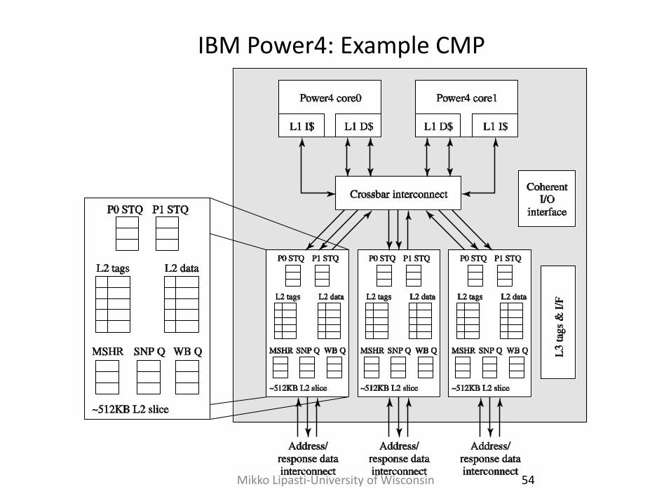
IBM Power4: Example CMP
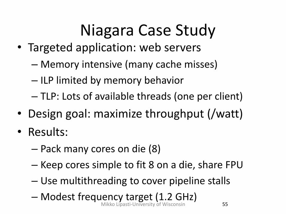
Niagara Case Study • Targeted application: web servers
– Memory intensive (many cache misses)
– ILP limited by memory behavior
– TLP: Lots of available threads (one per client)
• Design goal: maximize throughput (/watt)
• Results:
– Pack many cores on die (8)
– Keep cores simple to fit 8 on a die, share FPU
– Use multithreading to cover pipeline stalls
– Modest frequency target (1.2 GHz) 55 Mikko Lipasti-University of Wisconsin
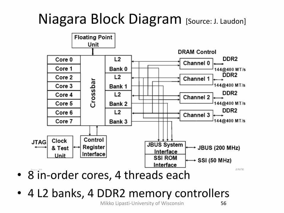
Niagara Block Diagram [Source: J. Laudon]
• 8 in-order cores, 4 threads each
• 4 L2 banks, 4 DDR2 memory controllers 56 Mikko Lipasti-University of Wisconsin
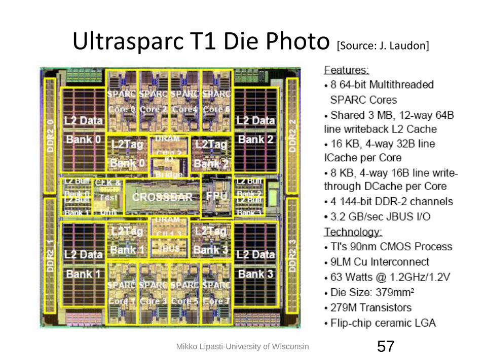
Ultrasparc T1 Die Photo [Source: J. Laudon]
57 Mikko Lipasti-University of Wisconsin
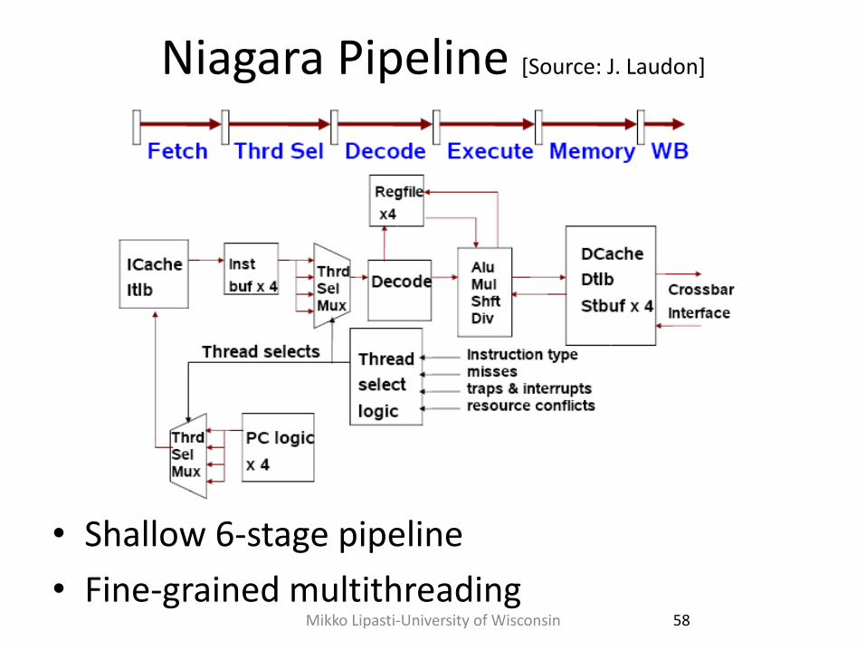
Niagara Pipeline [Source: J. Laudon]
• Shallow 6-stage pipeline
• Fine-grained multithreading 58 Mikko Lipasti-University of Wisconsin
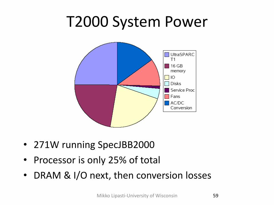
T2000 System Power
• 271W running SpecJBB2000
• Processor is only 25% of total
• DRAM & I/O next, then conversion losses
59 Mikko Lipasti-University of Wisconsin
Niagara Summary • Example of application-specific system
optimization
– Exploit application behavior
• TLP, cache misses, low ILP
– Build very efficient solution
• Downsides
– Loss of general-purpose suitability
– E.g. poorly suited for software development (parallel make, gcc)
– Very poor FP performance (fixed in Niagara 2)
60 Mikko Lipasti-University of Wisconsin
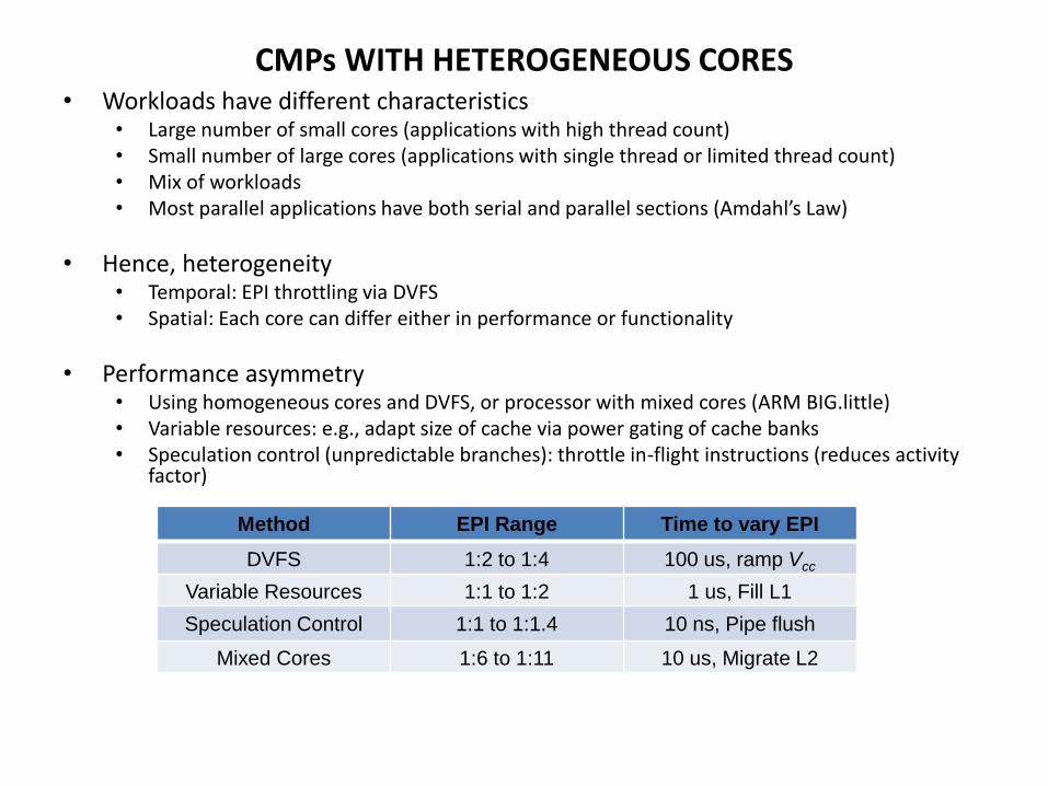
CMPs WITH HETEROGENEOUS CORES • Workloads have different characteristics
• Large number of small cores (applications with high thread count) • Small number of large cores (applications with single thread or limited thread count) • Mix of workloads • Most parallel applications have both serial and parallel sections (Amdahl’s Law)
• Hence, heterogeneity • Temporal: EPI throttling via DVFS • Spatial: Each core can differ either in performance or functionality
• Performance asymmetry • Using homogeneous cores and DVFS, or processor with mixed cores (ARM BIG.little) • Variable resources: e.g., adapt size of cache via power gating of cache banks • Speculation control (unpredictable branches): throttle in-flight instructions (reduces activity
factor)
Method EPI Range Time to vary EPI
DVFS 1:2 to 1:4 100 us, ramp Vcc
Variable Resources 1:1 to 1:2 1 us, Fill L1
Speculation Control 1:1 to 1:1.4 10 ns, Pipe flush
Mixed Cores 1:6 to 1:11 10 us, Migrate L2
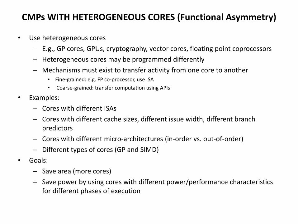
CMPs WITH HETEROGENEOUS CORES (Functional Asymmetry)
• Use heterogeneous cores
– E.g., GP cores, GPUs, cryptography, vector cores, floating point coprocessors
– Heterogeneous cores may be programmed differently
– Mechanisms must exist to transfer activity from one core to another • Fine-grained: e.g. FP co-processor, use ISA
• Coarse-grained: transfer computation using APIs
• Examples:
– Cores with different ISAs
– Cores with different cache sizes, different issue width, different branch predictors
– Cores with different micro-architectures (in-order vs. out-of-order)
– Different types of cores (GP and SIMD)
• Goals:
– Save area (more cores)
– Save power by using cores with different power/performance characteristics for different phases of execution
CMPs WITH HETEROGENEOUS CORES
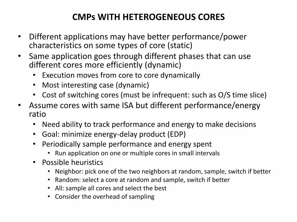
• Different applications may have better performance/power characteristics on some types of core (static)
• Same application goes through different phases that can use different cores more efficiently (dynamic) • Execution moves from core to core dynamically • Most interesting case (dynamic) • Cost of switching cores (must be infrequent: such as O/S time slice)
• Assume cores with same ISA but different performance/energy ratio • Need ability to track performance and energy to make decisions • Goal: minimize energy-delay product (EDP) • Periodically sample performance and energy spent
• Run application on one or multiple cores in small intervals
• Possible heuristics • Neighbor: pick one of the two neighbors at random, sample, switch if better • Random: select a core at random and sample, switch if better • All: sample all cores and select the best • Consider the overhead of sampling
64
Multicore Summary
• Objective: resource sharing, power efficiency – Where to connect
– Cache sharing
– Coherence
– How to connect
• Examples/case studies
• Heterogeneous CMPs
• Readings – [6] K. Olukotun, et al., "The Case for a Single-Chip Multiprocessor,"
ASPLOS-7, October 1996.
– [7] Kumar, R., et al., "Heterogeneous Chip Multiprocessors", IEEE Computer, pp. 32-38, Nov. 2005
Mikko Lipasti-University of Wisconsin
Lecture 3 Summary
• Multithreaded processors • Multicore processors
65 Mikko Lipasti-University of Wisconsin