Embed Size (px)
Citation preview
Connecting Cable 0 3 7 - 3 1 7 6 -
CABLE LENGTH IN FEET500 Ft. (152 m) max.
Example: 10 feet = 037-3176-010
Cable to be Belden Type 8102. Consult factory beforeselecting an alternate.
Electronics 34 - 4 4 2 - 10
FREQUENCY1 - 50 kHz, used with 385 transducer4 - 38 kHz, used with 384 transducerINPUT POWER0 - 120 VAC, 50/60 Hz1 - 240 VAC, 50/60 Hz2 - 24 VDC3 - 120 VAC, with heater & thermostat4 - 240 VAC, with heater & thermostat(4) SPDT 10 AMP RELAYSNEMA 4X NORYL HOUSING16 CHARACTER ALPHANUMERIC DISPLAY4-20 mA isolated and RS-232 OUTPUTSPECIAL OPTIONS0 - None1 - Mechanical totalizer2 - 31 day data logger (RS-232)3 - Mechanical totalizer and 31 day data logger (RS-232)
TABLE OF CONTENTS PAGEModel Identification . . . . . . . . . . . . . . . . . . . . . . . .1-2Measurement Range Calculations . . . . . . . . . . . . .3-4Installation . . . . . . . . . . . . . . . . . . . . . . . . . . . . . . .5-8Electrostatic Discharge Handling Procedure . . . . . . .9Wiring . . . . . . . . . . . . . . . . . . . . . . . . . . . . . . . . .9-12Unit Configuration . . . . . . . . . . . . . . . . . . . . . . .12-28
341/344 Quick Start . . . . . . . . . . . . . . . . . . . . . .13Complete Menu Structure . . . . . . . . . . . . . . . . .14
Troubleshooting . . . . . . . . . . . . . . . . . . . . . . . . .29-32Application Checklist . . . . . . . . . . . . . . . . . . . . . . .29Installation Checklist . . . . . . . . . . . . . . . . . . . . . . . .29Electrical Specifications . . . . . . . . . . . . . . . . . . . . .33Agency Approvals . . . . . . . . . . . . . . . . . . . . . . . . .33Dimensional Specifications . . . . . . . . . . . . . . . . . . .34Replacement Parts . . . . . . . . . . . . . . . . . . . . . . . . .35Product Warranty . . . . . . . . . . . . . . . . . . . . . . . . . .36Quality Assurance . . . . . . . . . . . . . . . . . . . . . . . . . .36Service Policy . . . . . . . . . . . . . . . . . . . . . . . . . . . . .36Return Material Procedure . . . . . . . . . . . . . . . . . . .36
MODEL IDENTIFICATIONEach Model 341/344 Ultrasonic Transmitter has a nameplateon which the model number of the unit is shown. Each modelnumber is coded to identify the options in that specific unit.Listed below and to the right are the definitions of each digitof the model number. By referring to these charts, theinstaller can determine exactly which options the transmittercontains.
Transducer 384- K -
PROCESS CONNECTION2 – 1" NPT5 - 2" NPT ➀KYNAR TRANSDUCER MATERIALTRANSDUCER HOUSING0 - No housing, w/ 35' (10.7 m) of cable1 - NEMA 4X/7/9, aluminum, 3⁄4" NPT *Y - NEMA 4X/7/9, 316 SS, 3⁄4" NPT **Requires connecting cable. (See below) TRANSDUCER MOUNTING BRACKET0 - No transducer mounting bracket3 - Wall mount for 2" NPT4 - Floor mount for 2" NPTTRANSDUCER LENGTH003 - 3" (76 mm) length010 - 10" (254 mm) length
MODEL IDENTIFICATION cont.
Refer to page 2 for Transducer Model 385.
Echotel®
Model 341 & 344 Ultrasonic Non-ContactTransmitters For Level,Volume, or Open Channel FlowSoftware version 2.0
Instruction Manual and Parts List
®
NOTE: If the Model 384 Transducer is to be mounted morethan 35' (10.7 m) away from the Model 344 Electronics, atransducer housing and interconnecting cable are required.➀ Process connection code 2 (1” NPT) cannot be ordered
with transducer housing code 1 or Y.
2
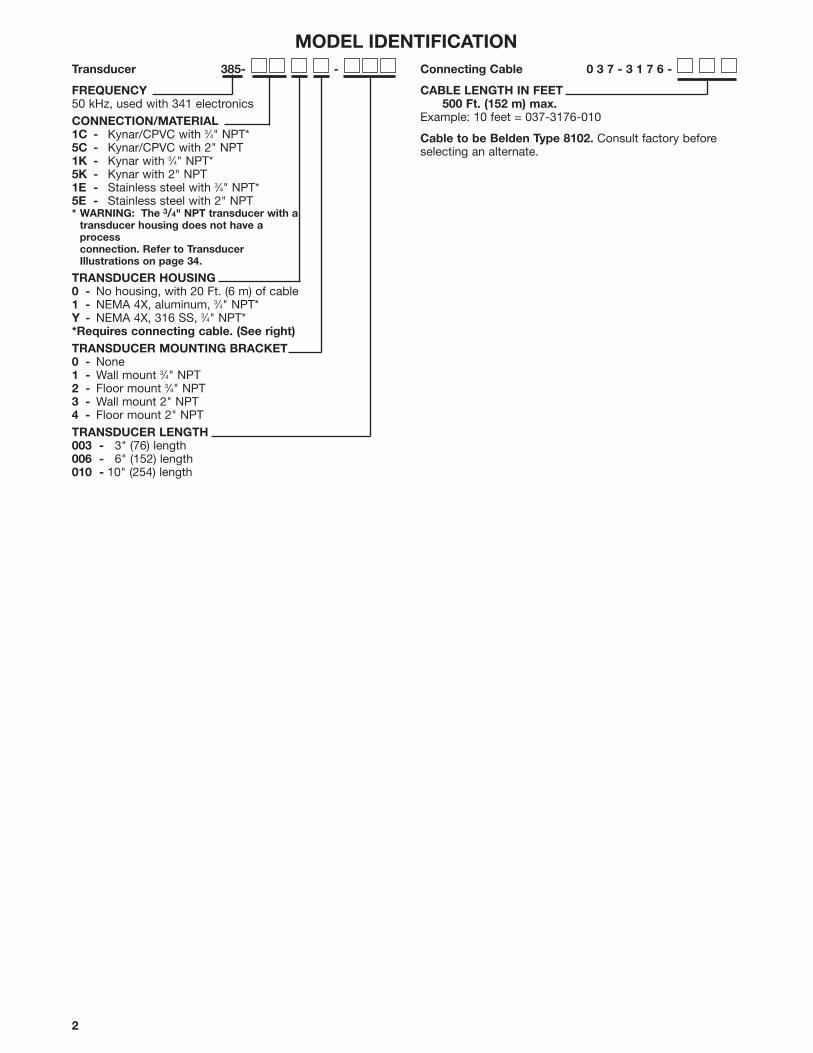
Transducer 385- -
FREQUENCY50 kHz, used with 341 electronicsCONNECTION/MATERIAL1C - Kynar/CPVC with 3⁄4" NPT*5C - Kynar/CPVC with 2" NPT1K - Kynar with 3⁄4" NPT*5K - Kynar with 2" NPT1E - Stainless steel with 3⁄4" NPT*5E - Stainless steel with 2" NPT* WARNING: The 3/4" NPT transducer with a
transducer housing does not have aprocessconnection. Refer to TransducerIllustrations on page 34.
TRANSDUCER HOUSING0 - No housing, with 20 Ft. (6 m) of cable1 - NEMA 4X, aluminum, 3⁄4" NPT*Y - NEMA 4X, 316 SS, 3⁄4" NPT**Requires connecting cable. (See right) TRANSDUCER MOUNTING BRACKET0 - None1 - Wall mount 3⁄4" NPT2 - Floor mount 3⁄4" NPT3 - Wall mount 2" NPT4 - Floor mount 2" NPTTRANSDUCER LENGTH003 - 3" (76) length006 - 6" (152) length010 - 10" (254) length
Connecting Cable 0 3 7 - 3 1 7 6 -
CABLE LENGTH IN FEET500 Ft. (152 m) max.
Example: 10 feet = 037-3176-010
Cable to be Belden Type 8102. Consult factory beforeselecting an alternate.
MODEL IDENTIFICATION
3
MEASUREMENT RANGE CALCULATIONS
Measurement range expectations
Ultrasonic non-contact devices are typically rated for amaximum range in ideal conditions. Experience has shownthat maximum range must be reduced for certain factors.Although the maximum range rating is somewhat conser-vative, each application must be evaluated for specificconditions.The operating parameters listed below can impact the maxi-mum range of measurement:
• Surface agitation• Vapors and steam• Beam spread interference • Transducer alignment• Foam• Dust• Air movement• Ambient temperature• Pressure
How to calculateTo calculate the performance that a particular applicationwill have, using the chart on page 4:
1. Select one condition from each of the operatingparameters that best describes your application.
2. Enter the corresponding performance multiplier valuein the application column.
3. Multiply all values together.
4. Multiply the result from step 3 by the maximumpotential range (35' for the 344 and 25' for the 341);this yields a value that is the maximum allowablemeasurement range for this application.
Example:The vessel is a closed-top tank, uninsulated, 26 feet tall.
Surface agitation: Expect slight agitation from fill line.Performance multiplier 0.9.
Vapor and steam: The maximum process temperature is +110° F; slight vapor is expected.Performance multiplier 0.9.
Beam interference: No interference exists.Performance multiplier 1.0.
Transducer alignment: The transducer will be perpen-dicular to the liquid surface.Performance multiplier 1.0
Foam: None. Performance multiplier 1.0Dust: None. Performance multiplier 1.0Air movement: None. Performance multiplier 1.0Ambient temp.: +30 to +80° F.
Performance multiplier 1.0Pressure: +40 PSIG.
Performance multiplier 1.0Will the Model 344 work for this application?
Calculation:Multiplied values of all application columns:0.9 x 0.9 x 1.0 x 1.0 x 1.0 x 1.0 x 1.0 x 1.0 x 1.0 x 35 feet (maximum) = 28.35 feet
The calculation yields 28.35 feet as the new maximum range.Since the tank is 26 feet tall, this application will give satis-factory results.
NOTE: The performance multipliers provided are conser-vative estimates. Since these factors are subjective, theestimates have been designed to provide a very high con-fidence of system success. Contact the factory if there areany questions concerning the interpretation of any of thesevalues.
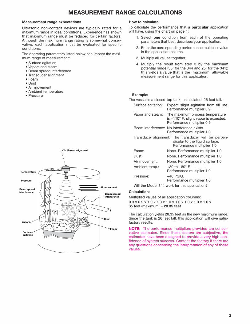
Sensor alignment
Temperature
Pressure
Beam spreadinterference
Beam spreadinterference
Air movement
DustVapors
FoamSurfaceagitation
4
MEASUREMENT RANGE CALCULATIONS
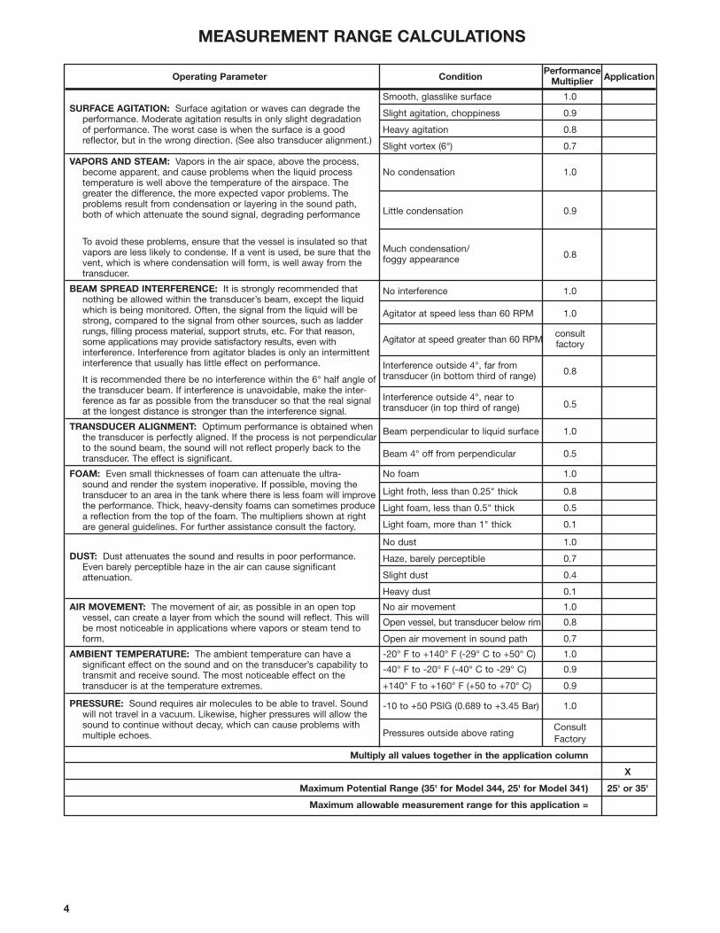
Operating Parameter ConditionPerformance
ApplicationMultiplier
SURFACE AGITATION: Surface agitation or waves can degrade theSmooth, glasslike surface 1.0
performance. Moderate agitation results in only slight degradationSlight agitation, choppiness 0.9
of performance. The worst case is when the surface is a good Heavy agitation 0.8reflector, but in the wrong direction. (See also transducer alignment.)
Slight vortex (6°) 0.7
VAPORS AND STEAM: Vapors in the air space, above the process, become apparent, and cause problems when the liquid process No condensation 1.0temperature is well above the temperature of the airspace. The greater the difference, the more expected vapor problems. Theproblems result from condensation or layering in the sound path,both of which attenuate the sound signal, degrading performance Little condensation 0.9
To avoid these problems, ensure that the vessel is insulated so thatvapors are less likely to condense. If a vent is used, be sure that the Much condensation/
0.8vent, which is where condensation will form, is well away from the foggy appearance
transducer.
BEAM SPREAD INTERFERENCE: It is strongly recommended that No interference 1.0nothing be allowed within the transducer’s beam, except the liquid which is being monitored. Often, the signal from the liquid will be Agitator at speed less than 60 RPM 1.0strong, compared to the signal from other sources, such as ladderrungs, filling process material, support struts, etc. For that reason,
Agitator at speed greater than 60 RPMconsult
some applications may provide satisfactory results, even with factoryinterference. Interference from agitator blades is only an intermittent interference that usually has little effect on performance. Interference outside 4°, far from
0.8It is recommended there be no interference within the 6° half angle of transducer (in bottom third of range)
the transducer beam. If interference is unavoidable, make the inter-ference as far as possible from the transducer so that the real signal Interference outside 4°, near to
0.5at the longest distance is stronger than the interference signal. transducer (in top third of range)
TRANSDUCER ALIGNMENT: Optimum performance is obtained when Beam perpendicular to liquid surface 1.0the transducer is perfectly aligned. If the process is not perpendicular to the sound beam, the sound will not reflect properly back to the transducer. The effect is significant. Beam 4° off from perpendicular 0.5
FOAM: Even small thicknesses of foam can attenuate the ultra- No foam 1.0sound and render the system inoperative. If possible, moving the
Light froth, less than 0.25" thick 0.8transducer to an area in the tank where there is less foam will improvethe performance. Thick, heavy-density foams can sometimes produce Light foam, less than 0.5" thick 0.5a reflection from the top of the foam. The multipliers shown at right
Light foam, more than 1" thick 0.1are general guidelines. For further assistance consult the factory.
DUST: Dust attenuates the sound and results in poor performance.
No dust 1.0
Even barely perceptible haze in the air can cause significantHaze, barely perceptible 0.7
attenuation. Slight dust 0.4
Heavy dust 0.1
AIR MOVEMENT: The movement of air, as possible in an open top No air movement 1.0vessel, can create a layer from which the sound will reflect. This will Open vessel, but transducer below rim 0.8be most noticeable in applications where vapors or steam tend toform. Open air movement in sound path 0.7
AMBIENT TEMPERATURE: The ambient temperature can have a -20° F to +140° F (-29° C to +50° C) 1.0significant effect on the sound and on the transducer’s capability to -40° F to -20° F (-40° C to -29° C) 0.9transmit and receive sound. The most noticeable effect on the transducer is at the temperature extremes. +140° F to +160° F (+50 to +70° C) 0.9
PRESSURE: Sound requires air molecules to be able to travel. Sound -10 to +50 PSIG (0.689 to +3.45 Bar) 1.0will not travel in a vacuum. Likewise, higher pressures will allow thesound to continue without decay, which can cause problems with
Pressures outside above ratingConsult
multiple echoes. Factory
Multiply all values together in the application column
X
Maximum Potential Range (35' for Model 344, 25' for Model 341) 25' or 35'
Maximum allowable measurement range for this application =

5
INSTALLATION
TRANSMITTER MOUNTING LOCATION
The transmitter enclosure should be securely fastened to anappropriate supporting structure, in a location that permitseasy access for maintenance. Avoid locations that areexposed to direct sunlight, flooding, high levels of radiatedelectromagnetic interference, and excessive vibration orshock. If mounted in a location where there is intense,extreme, direct sunlight, a sun shade is recommended.
TRANSDUCER MOUNTING LOCATION
Model 384/385 transducers must be mounted directly overthe material to be measured. This may be accomplished byflange or bracket mounting. Both floor and wall mount trans-ducer brackets are available for use over open tanks orchannels. Flange mounts are available for use with closedvessels.
Proper mounting and wiring of the ultrasonic transducer is ofthe utmost importance. Both the accuracy and the reliabilityof the Model 341/344 can be adversely affected if the trans-ducer is mounted improperly.
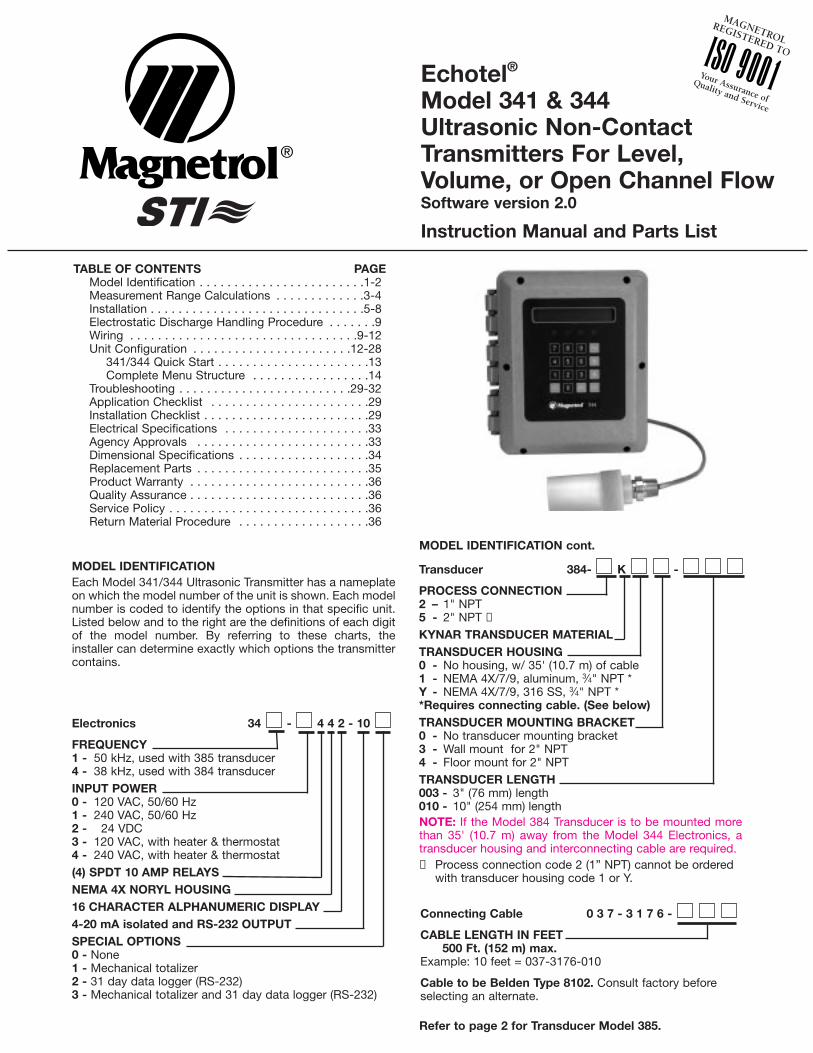
NOTE: The 341/344 requires a “dead band” blankingdistance between the transducer and the maximum level ofmaterial. The minimum dead band is 12 inches (305 mm)for Model 341 and 18 inches (460 mm) for Model 344. Attemperatures above 140° F minimum, dead band is 18" foreither model. Maximum dead band should be limited toapproximately 10 feet (3 m) as this blanking distance isextended at the expense of the useful span over which theinstrument operates.
CAUTION: Please read the entire installation section carefully prior to starting installation.
Sensor
Air
Liquid
Dead Band12" (305 mm) minimum
(Model 341),18" (460 mm) minimum
(Model 344)
Flange
Model 34125 feet (7.6 m)
maximum
Model 34435 feet (10.7 m)
maximum
Model 34124 feet (7.3 m)
maximum
Model 34433.5 feet (10.2 m)
maximum
Range
Span
DESCRIPTION
Model 341/344 non-contact continuous transmitters per-form level, volume, or open channel flow measurements ofliquids and slurries. Non-contacting ultrasonic technology isused, which enables a wide variety of industrial and munici-pal applications to be reliably measured. The ultrasonictransducer may be mounted up to 500 feet (152 m) from thetransmitter.
PRINCIPLE OF OPERATION
Pulses generated by the microprocessor-based electronicsare transmitted through the analog processor to the ultra-sonic transducer. The transducer directs an ultrasonic pulseto the surface level. The returning echo/signal is detected bythe transducer. A microprocessor converts the signal into adigital representation of the level, flow or volume measure-ment. This representation is displayed in the unit of meas-urement selected by the user during the Configuration/Set-up process.
UNPACKING
Unpack the instrument carefully. Make sure all componentshave been removed from the packing material. Inspect allcomponents for damage. Report any concealed damage tothe carrier within 24 hours. Check the contents of the pack-ing slip and report any discrepancies to the factory. Checkthe nameplate model number to be sure it agrees with thepacking slip and purchase order. Check and record the seri-al number for future reference when ordering parts.
Figure 1Transducer Mounting Location

6
INSTALLATION cont.
TRANSMITTER MOUNTING PROCEDURE
There are two predrilled holes in the enclosure forconnecting 1/2" NEMA 4X conduit; one for power and one fortransducer cable wiring. Refer to Figure 2.
GENERAL TRANSDUCER MOUNTING REQUIREMENTS1. Whenever possible, locate the transducer to avoid
obstructions between the transducer face and the sur-face of the level being tracked. Ultrasound radiates fromthe transducer with a beam spread of approximatelytwelve (12) degrees. Objects that extend into the sonicbeam can produce echoes that mask the true level. Thefalse target buffering feature allows for blanking out upto nine obstructions. Refer to page 25.
Sonic Beam DispersionDistance from Beam Minimum OffsetTransducer Face Diameter From Tank Wall
2' . . . . . . . . . . . . .0.42' . . . . . . . . . . . . .2.52"
4' . . . . . . . . . . . . .0.84' . . . . . . . . . . . . .5.04"
6' . . . . . . . . . . . . .1.25' . . . . . . . . . . . . . .7.5"
8' . . . . . . . . . . . . .1.67' . . . . . . . . . . . .10.02"
10' . . . . . . . . . . . . . .2.1' . . . . . . . . . . . . .12.6"
12' . . . . . . . . . . . . . .2.5' . . . . . . . . . . . . . .15"
14' . . . . . . . . . . . . . .2.9' . . . . . . . . . . . . .17.4"
16' . . . . . . . . . . . . . .3.3' . . . . . . . . . . . . .19.8"
18' . . . . . . . . . . . . .3.76' . . . . . . . . . . . . .22.56
20' . . . . . . . . . . . . .4.18' . . . . . . . . . . . .25.08"
22' . . . . . . . . . . . . . .4.6' . . . . . . . . . . . . .27.6"
24' . . . . . . . . . . . . .5.02' . . . . . . . . . . . .30.12"
26' . . . . . . . . . . . . .5.44' . . . . . . . . . . . .32.64"
28' . . . . . . . . . . . . .5.86' . . . . . . . . . . . .35.16"
30' . . . . . . . . . . . . .6.28' . . . . . . . . . . . .37.68"
32' . . . . . . . . . . . . .6.80' . . . . . . . . . . . . .40.8"
35' . . . . . . . . . . . . .7.44' . . . . . . . . . . . .44.64"
2. Position the transducer so that the radiating surface ortransducer face is exactly parallel to the measurementsurface. This will provide the strongest return signalsand enhance the reliability of the Model 341/344.
3. In applications where the material level may come intothe dead band or where the full tank height will be used,the transducer must be mounted in a short, flanged pipestub. The diameter of the stub should be at least 8 inch-es (203 mm) and its length should be limited to 11 inch-es (279 mm) from transducer face. Refer to Figure 4.
NOTE: Transducer face should be mounted as close tothe vessel ceiling as possible.
Figure 3Electronics Mounting Tabs
Figure 2Electronics Mounting Holes
1. Open the door of the unit.2. Drill holes in the enclosure as required for additional
wiring. Be careful not to damage the printed circuitboards. Be sure that the PC boards are not damaged orcontaminated when removing filings and/or debris fromthe housing.
3. Provide watertight seals for all wiring entrances in theenclosure to maintain the NEMA 4X rating.
4. Mount the enclosure to a wall or flat surface using theappropriate screws or bolts. The mounting tabs on theback of the enclosure can be rotated to the sides, or topand bottom to facilitate mounting. Refer to Figure 3.
5. Install conduit for power and control wiring. Be sure allconnections to the enclosure maintain a NEMA 4X rat-ing.
6. Close the transmitter door until it is time to wire thetransmitter. Proceed to mount the transducer.

7
Figure 4Transducer Mounting for Full Tanks
INSTALLATION cont.
4. Avoid installing the transducer in tank top openings thatexhaust heated air or vapors. The boundaries betweenthe vapors and the outside air often represent acousticimpedance gradients that can cause troublesomesound reflections. In those installations, the transducershould be mounted well away from the opening insidethe tank, or in a pipe stub as illustrated here. Refer toFigures 4 and 5.
5. To prevent electromagnetic noise from disrupting thenormal operation of the Model 341/344, it is recom-mended that each transducer cable be run in its ownconduit, separated from other cables and wiring.
6. There are three Mounting Procedures discussed onpages 7 and 8. Locate the mounting procedure from thechart below and proceed to the appropriate instruc-tions.
Figure 5Transducer Mounting for Tanks With Exhaust
GENERAL TRANSDUCER MOUNTING REQUIREMENTS cont.
NPT Mounting Housing Procedure Page3⁄4" or 2" bracket without A 73⁄4" or 2" bracket with B 8
3⁄4", 1", or 2" flange without C 83⁄4" or 2" flange with C 8
CAUTION: Do NOT install transducers in the centerof domed roof tanks. Locate transducers 1' to 3' offcenter to minimize false/multiple echoes being reflect-ed off the domed roof.
2. Secure the bracket to the wall, floor, or vessel as appro-priate with four 3/8" screws. Refer to the mounting hole pattern as shown in the dimensional drawings onpage 34.
3. Pull transducer cable through mounting bracket andscrew transducer into fitting in mounting bracket.
4. Providing conduit from the transducer to the transmitterenclosure, carefully pull the transducer cable throughthe conduit toward the transmitter enclosure. This cablewill be connected in the “Transducer Wiring WithoutTransducer Housing” section on page 10.
5. Tighten the conduit to the nipple on the top of the trans-ducer. Refer to Figure 7.
NOTE: In high humidity applications, it is recommended thatthe transducer wiring be completely immersed in an insulat-ing compound where the conduit connects to the transduc-er. (3M #4441 Gella Re-enterable Encapsulating Compoundor equivalent.)
TRANSDUCER MOUNTING PROCEDURE A3⁄4" NPT or 2" NPT Transducer with Factory SuppliedMounting Bracket, Without Transducer Housing
NOTE: Be sure the transducer location meets the require-ments discussed under “General Transducer MountingRequirements” on pages 6 and 7.
1. Position the bracket such that the transducer mounting hole is positioned over the open tank or channel. Refer to Figure 6.
Figure 6
6. Proceed to the "Wiring" section on page 9.
Figure 7
Transducer
Conduit
Transducer Cable
MountingBracket
Tank Wall
Wall Mount Bracket
Transducer
ThreadedMountingConnection
Conduit
CAUTION: HAND TIGHTEN ONLY. Do NOT use a pipewrench or other tools when tightening the transducer.Use teflon tape on thread for 316 stainless steel trans-ducer. Avoid excessive twisting of the transducer cable.
8" (203) Minimum I.D.
2" NPT
Transducer
This end welded or flanged to tank
Pipe Stub
Maximum 11" (279 mm) or less
8
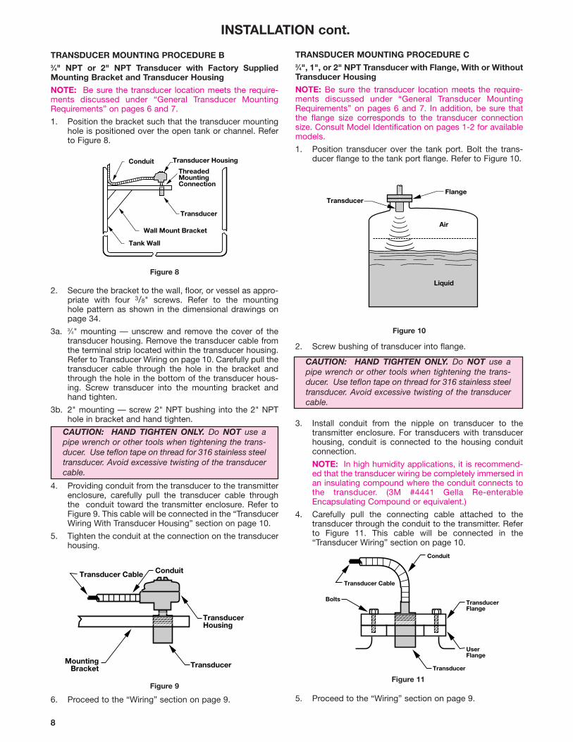
2. Secure the bracket to the wall, floor, or vessel as appro-priate with four 3/8" screws. Refer to the mounting hole pattern as shown in the dimensional drawings onpage 34.
3a. 3⁄4" mounting — unscrew and remove the cover of thetransducer housing. Remove the transducer cable fromthe terminal strip located within the transducer housing.Refer to Transducer Wiring on page 10. Carefully pull thetransducer cable through the hole in the bracket andthrough the hole in the bottom of the transducer hous-ing. Screw transducer into the mounting bracket andhand tighten.
3b. 2" mounting — screw 2" NPT bushing into the 2" NPThole in bracket and hand tighten.
4. Providing conduit from the transducer to the transmitterenclosure, carefully pull the transducer cable throughthe conduit toward the transmitter enclosure. Refer toFigure 9. This cable will be connected in the “TransducerWiring With Transducer Housing” section on page 10.
5. Tighten the conduit at the connection on the transducerhousing.
INSTALLATION cont.
TRANSDUCER MOUNTING PROCEDURE B3⁄4" NPT or 2" NPT Transducer with Factory SuppliedMounting Bracket and Transducer Housing
NOTE: Be sure the transducer location meets the require-ments discussed under “General Transducer MountingRequirements” on pages 6 and 7.
1. Position the bracket such that the transducer mountinghole is positioned over the open tank or channel. Referto Figure 8.
TRANSDUCER MOUNTING PROCEDURE C3⁄4", 1", or 2" NPT Transducer with Flange, With or WithoutTransducer Housing
NOTE: Be sure the transducer location meets the require-ments discussed under “General Transducer MountingRequirements” on pages 6 and 7. In addition, be sure thatthe flange size corresponds to the transducer connectionsize. Consult Model Identification on pages 1-2 for availablemodels.
1. Position transducer over the tank port. Bolt the trans-ducer flange to the tank port flange. Refer to Figure 10.
Figure 8
6. Proceed to the “Wiring” section on page 9. 5. Proceed to the “Wiring” section on page 9.
Figure 9Figure 11
2. Screw bushing of transducer into flange.
3. Install conduit from the nipple on transducer to thetransmitter enclosure. For transducers with transducerhousing, conduit is connected to the housing conduitconnection.
NOTE: In high humidity applications, it is recommend-ed that the transducer wiring be completely immersed inan insulating compound where the conduit connects tothe transducer. (3M #4441 Gella Re-enterableEncapsulating Compound or equivalent.)
4. Carefully pull the connecting cable attached to thetransducer through the conduit to the transmitter. Referto Figure 11. This cable will be connected in the“Transducer Wiring” section on page 10.
Figure 10
Tank Wall
Wall Mount Bracket
Transducer
Transducer HousingConduitThreadedMountingConnection
MountingBracket
TransducerHousing
ConduitTransducer Cable
Transducer
Transducer
Air
Liquid
Flange
Transducer
Transducer Cable
Bolts TransducerFlange
UserFlange
Conduit
CAUTION: HAND TIGHTEN ONLY. Do NOT use apipe wrench or other tools when tightening the trans-ducer. Use teflon tape on thread for 316 stainless steeltransducer. Avoid excessive twisting of the transducercable.
CAUTION: HAND TIGHTEN ONLY. Do NOT use apipe wrench or other tools when tightening the trans-ducer. Use teflon tape on thread for 316 stainless steeltransducer. Avoid excessive twisting of the transducercable.
9
+
+
+
TB5
-
L1 (+)
L2/N (-)GND (+) (-)
LOOP 4-20
TB1
NC CO NO NC CO NORELAY #1 RELAY #2
TB3
RS
485
RS
232
NC
CO
NO
NC
CO
NO
RE
LAY
#3
RE
LAY
#4
TB
4T
B2
Figure 12341/344 Motherboard (shown with daughter board removed)
U.S. Europe U.K.
Line 1 (HI) Black Blue Brown
Line 2 Neutral White Black Blue
Ground Green/Yellow Green/Yellow Green/Yellow
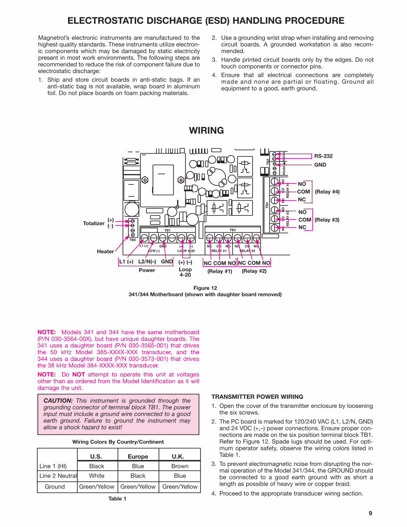
NOTE: Models 341 and 344 have the same motherboard(P/N 030-3564-00X), but have unique daughter boards. The341 uses a daughter board (P/N 030-3565-001) that drivesthe 50 kHz Model 385-XXXX-XXX transducer, and the 344 uses a daughter board (P/N 030-3573-001) that drivesthe 38 kHz Model 384-XXXX-XXX transducer.
NOTE: Do NOT attempt to operate this unit at voltagesother than as ordered from the Model Identification as it willdamage the unit.
CAUTION: This instrument is grounded through thegrounding connector of terminal block TB1. The powerinput must include a ground wire connected to a goodearth ground. Failure to ground the instrument mayallow a shock hazard to exist!
TRANSMITTER POWER WIRING
1. Open the cover of the transmitter enclosure by looseningthe six screws.
2. The PC board is marked for 120/240 VAC (L1, L2/N, GND)and 24 VDC (+,–) power connections. Ensure proper con-nections are made on the six position terminal block TB1.Refer to Figure 12. Spade lugs should be used. For opti-mum operator safety, observe the wiring colors listed inTable 1.
3. To prevent electromagnetic noise from disrupting the nor-mal operation of the Model 341/344, the GROUND shouldbe connected to a good earth ground with as short alength as possible of heavy wire or copper braid.
4. Proceed to the appropriate transducer wiring section.Table 1
WIRING
Wiring Colors By Country/Continent
COM (Relay #4)
NC COM NO
(Relay #2)NC COM NO
(Relay #1)
L1 (+) L2/N(–) GND
Power
Heater
Totalizer
NO
NC
COM (Relay #3)NO
NC(+)(_)
(+) (–)Loop4-20
ELECTROSTATIC DISCHARGE (ESD) HANDLING PROCEDURE
Magnetrol’s electronic instruments are manufactured to thehighest quality standards. These instruments utilize electron-ic components which may be damaged by static electricitypresent in most work environments. The following steps arerecommended to reduce the risk of component failure due toelectrostatic discharge:1. Ship and store circuit boards in anti-static bags. If an
anti-static bag is not available, wrap board in aluminumfoil. Do not place boards on foam packing materials.
2. Use a grounding wrist strap when installing and removingcircuit boards. A grounded workstation is also recom-mended.
3. Handle printed circuit boards only by the edges. Do nottouch components or connector pins.
4. Ensure that all electrical connections are completelymade and none are partial or floating. Ground all equipment to a good, earth ground.
RS-232
GND
344 Daughter Board
TB8
TB
6T
B7
10
WIRING cont.
TRANSDUCER WIRING cont.
With a Transducer Housing
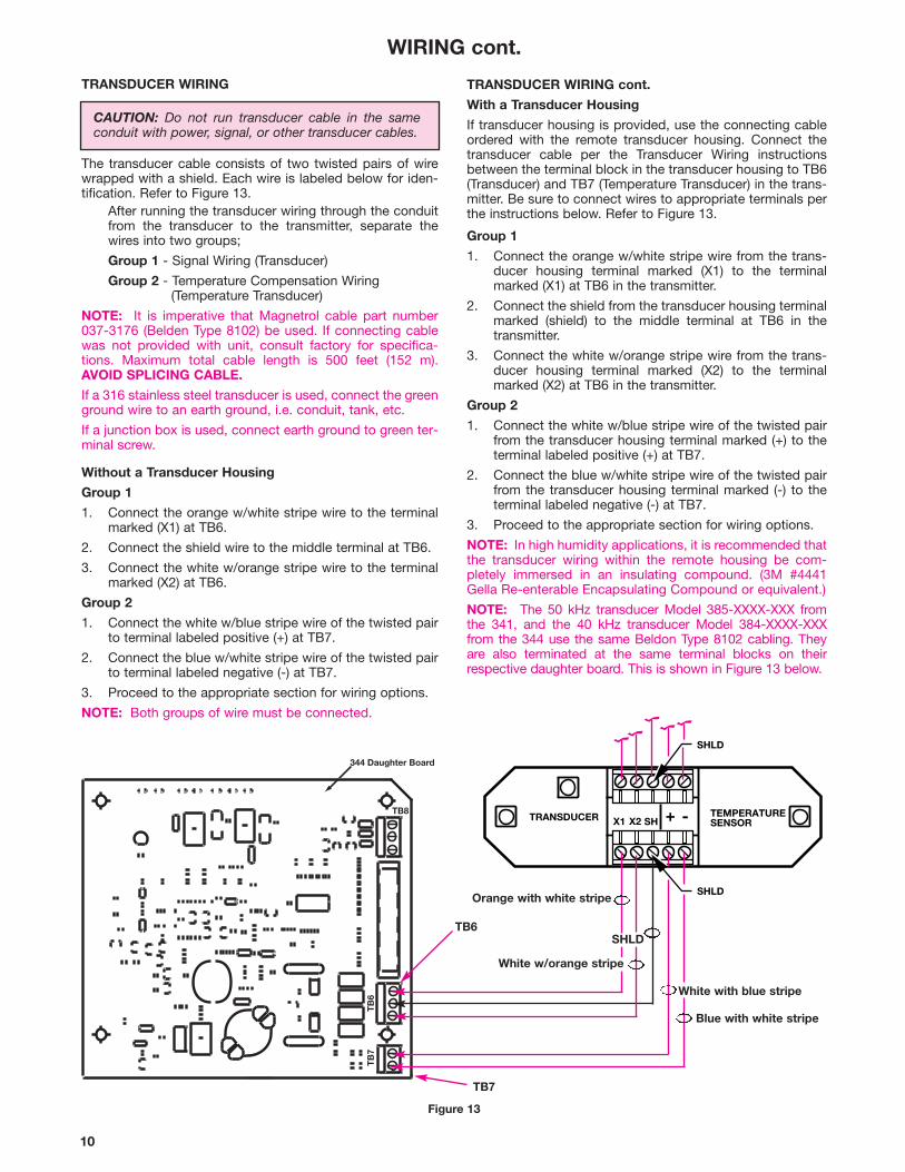
If transducer housing is provided, use the connecting cableordered with the remote transducer housing. Connect thetransducer cable per the Transducer Wiring instructionsbetween the terminal block in the transducer housing to TB6(Transducer) and TB7 (Temperature Transducer) in the trans-mitter. Be sure to connect wires to appropriate terminals perthe instructions below. Refer to Figure 13.
Group 1
1. Connect the orange w/white stripe wire from the trans-ducer housing terminal marked (X1) to the terminalmarked (X1) at TB6 in the transmitter.
2. Connect the shield from the transducer housing terminalmarked (shield) to the middle terminal at TB6 in thetransmitter.
3. Connect the white w/orange stripe wire from the trans-ducer housing terminal marked (X2) to the terminalmarked (X2) at TB6 in the transmitter.
Group 2
1. Connect the white w/blue stripe wire of the twisted pairfrom the transducer housing terminal marked (+) to theterminal labeled positive (+) at TB7.
2. Connect the blue w/white stripe wire of the twisted pairfrom the transducer housing terminal marked (-) to theterminal labeled negative (-) at TB7.
3. Proceed to the appropriate section for wiring options.
NOTE: In high humidity applications, it is recommended thatthe transducer wiring within the remote housing be com-pletely immersed in an insulating compound. (3M #4441Gella Re-enterable Encapsulating Compound or equivalent.)
NOTE: The 50 kHz transducer Model 385-XXXX-XXX fromthe 341, and the 40 kHz transducer Model 384-XXXX-XXXfrom the 344 use the same Beldon Type 8102 cabling. Theyare also terminated at the same terminal blocks on theirrespective daughter board. This is shown in Figure 13 below.
TRANSDUCER WIRING
The transducer cable consists of two twisted pairs of wirewrapped with a shield. Each wire is labeled below for iden-tification. Refer to Figure 13.
After running the transducer wiring through the conduitfrom the transducer to the transmitter, separate thewires into two groups;
Group 1 - Signal Wiring (Transducer)
Group 2 - Temperature Compensation Wiring (Temperature Transducer)
NOTE: It is imperative that Magnetrol cable part number037-3176 (Belden Type 8102) be used. If connecting cablewas not provided with unit, consult factory for specifica-tions. Maximum total cable length is 500 feet (152 m).AVOID SPLICING CABLE.
If a 316 stainless steel transducer is used, connect the greenground wire to an earth ground, i.e. conduit, tank, etc.
If a junction box is used, connect earth ground to green ter-minal screw.
Without a Transducer Housing
Group 1
1. Connect the orange w/white stripe wire to the terminalmarked (X1) at TB6.
2. Connect the shield wire to the middle terminal at TB6.
3. Connect the white w/orange stripe wire to the terminalmarked (X2) at TB6.
Group 2
1. Connect the white w/blue stripe wire of the twisted pairto terminal labeled positive (+) at TB7.
2. Connect the blue w/white stripe wire of the twisted pairto terminal labeled negative (-) at TB7.
3. Proceed to the appropriate section for wiring options.
NOTE: Both groups of wire must be connected.
TRANSDUCER TEMPERATURESENSORX1 X2 + -
SHLD
SHLD
SH
Figure 13
TB6
Blue with white stripe
Orange with white stripe
White w/orange stripe
White with blue stripe
TB7
CAUTION: Do not run transducer cable in the sameconduit with power, signal, or other transducer cables.
SHLD

11
WIRING cont.
1. Connect two-wire leads to the desired relay connection,1 through 4. Connect one wire to the terminal labeled(COM) and the other to the terminal for the desired contact function, (NC) for normally closed or (NO) for normally open. Repeat this step for each relay.
2. Refer to Relay Settings in the Configuration section onpage 23 and 24 for information on configuring the relays.
3. Proceed to wire any remaining options the unit mayhave, as shown in the next two pages.
NOTE: If the device to be operated by the relay has aninductive load a separate power supply should be used forthe electronics.
RELAY OUTPUT WIRING
The 341/344 unit is supplied with 4 relays that can operateas normal independent contact closures or used as dedicat-ed relays as follows:
Relay 1 Normal
Relay 2 Normal/Lead/Lag Pump Alternation (with Relay 1)
Relay 3 Normal/Dedicated Fault
Relay 4 Normal/Sampler Contact
Relay connections are supplied on the motherboard asshown in Figure 12 and 14.
OUTPUT SIGNAL WIRING
4-20 mA DC Output cont.
4-20 mA DC output connections can be made at terminalblock TB1, located inside the transmitter housing. Refer toFigure 15. The loop is optically isolated, has non-groundedoutputs, and can drive a 1000 ohm load.
1. Connect the positive (+) shielded twisted pair wire fromthe load to terminal LOOP (+).
2. Connect the negative (-) shielded twisted pair wire fromthe load to terminal LOOP (-).
Figure 14
3. Proceed to the "Unit Configuration" section onpage 12.
NOTE: The shield should be connected to an earth groundat only one location.
Transducer Synchronization
Transducer synchronization is a feature offered with theModel 344 unit only. It allows you to run the cabling frommultiple Model 384 transducers in the same conduit. Thisprevents the possibility for cross talk to occur from oneModel 344 to another. The synchronization scheme involvesthe use of one 344 unit operating as a master, and one ormore other units operating as slaves.
Multiple Model 344 units should be wired together utilizingTB8 (Figure 16) on the daughter board as shown in Figure 17below. The master unit synchronizes the ultrasonic signalssuch that all units transmit their ultrasonic signals at thesame time. This eliminates the possibility of cross talk occur-ring. No calibration or configuration is necessary other thanthe wiring shown below.
Figure 15
Figure 16(344 Daughter Board)
Synchronization Terminal Block – TB8
SYNC. IN
SYNC. OUT
GR. REF.
SYNC. OUT
GR. REF.
SYNC. IN
GR. REF.
SYNC. IN
GR. REF.
SLAVE UNITMASTER UNIT SLAVE UNIT
NC CO NO NC CO NORELAY #1 RELAY #2
TB3
RS
485
RS
232
NC
CO
NO
NC
CO
NO
RE
LAY
#3
RE
LAY
#4
TB
4T
B2
++
TB5
-TOT.
(TOTALIZER)
HEAT (HEATER)
L1 (+)
L2/N (-)GND (+) (-)
LOOP 4-20
TB1
Figure 17Synchronization Wiring Diagram

12
7
TB2(341/344 Transmitter)
DB 25F Connector(Laptop)
RX
TX3
2
Figure 18
RS-232 Output
NOTE: The RS-232 output is only used for downloadinginformation from the optional 31 day data logger.
RS-232 output connection is located at TB2 and labeled TXand RX. Refer to Figure 18.
This connection for the RS-232 is utilized for the hookup of alaptop computer. In the laptop mode, one can downloadstored data, if unit is equipped with data logging option.
The cable to connect the laptop computer to the Model341/344 must be supplied by the user. Configure this cableas shown in Figure 18 below. Downloading instructions are inthe Laptop Section on page 28.
For numeric entry of parameters.
For decimal numeric entries.
To exit any programming area and return toa measurement mode.
For writing new parameter values intomemory. Also used to exit the parameterentry mode, if pressed prior to enteringnumeric parameter values.
To sequentially access other parameterprocedures. In addition, parameters maybe skipped over without affecting theirstored values. The DOWN arrow will act asa backspace for correcting data entryerrors.
All values for Parameter Entry procedures follow the transac-tion flow below:
GENERAL CONFIGURATION INSTRUCTIONS
The Model 341/344 ultrasonic non-contact continuous trans-mitter contains a microprocessor-based operator interfacewhich allows for easy configuration of level, flow orvolume applications. These features are built into the trans-mitter and are entered via a keypad located on the front ofthe unit.
This operator interface and the instructions for the UnitConfiguration are broken down into six main groups ofmenus, as follows:
MEASURED VALUES To view measured values
SYSTEM CONFIG First time configuration (Essential programming information for mea-surements)
I/O CONFIG Configure input/output functions
ADVANCED CONFIG Additional values that affect the units performance
DIAGNOSTICS Test functions
LAPTOP Download data logging to Laptop computer. (With optional Data Logger only)
PASSWORDS
The Model 341/344 has two types of passwords that can beused to protect configuration parameters. They are as follows:
GENERAL PASSWORD - The General Password is usedfor the System Config and the I/O Config portion of theMenu Structure. Any time a change is made to parameters inthese menus, ie. range, span, 4-20 mA, relays, etc., theModel 341/344 will prompt the operator to enter a password.This password can be any one to six character numeric com-bination that is easy for the operator to remember.
SUPERVISORY PASSWORD - The Supervisory Pass-word is used for the Advanced Config portion of the MenuStructure. This password is used to protect values that canaffect the performance and/or accuracy of the device.
NOTE: Although the Supervisory Password is normally usedin the Advanced Config menu, this password can also beused in any portion of the menu. The Supervisory Passwordoverrides the General Password.
0 - 9
.
DEL
OPERATOR KEYPAD
All Unit Configuration instructions in this manual will showthe local transmitter display exactly as it will appear to theoperator.
The operator interface to the 341/344 is via a keypad con-sisting of the following keys:
WIRING cont.
Password
CAUTION: The Model 341/344 is shipped from thefactory with the password set at 0341. If the passwordis misplaced or forgotten, please consult the factory forassistance.
FIRST LEVEL PROGRAMMING MENUS
Measured Values
System Configuration
I/O Configuration
Advanced Configuration
Diagnostics
Laptop
>>>QUIT<<<
Model 341/344
ENT
Sup Password
UNIT CONFIGURATION cont.PASSWORDS cont.
The Passwords can be changed at any time via theAdvanced Config mode.
If an invalid password is entered, the display will readPassword Invalid. By pressing the DEL key twice, the unitwill continue to operate with the previous programmedparameters.
UNIT CONFIGURATION
13
341/344 QUICK START PROGRAM cont.
For this quick start scheme, we will guide the user throughone relay setup in the level only mode and scaling the 4-20mA output.
With I/O Config displayed, press ENT and the display willread Relay Settings. Press ENT here to display Relay #___.For this quick start scheme, press the #1 key to indicate relay#1. Press ENT at this point and the display will read Relay 1Disabled. The user can toggle with the UP or DOWN arrowkeys to disable or enable the relay. Select Enable and pressthe ENT key. The 341/344 will prompt you to key in the TurnOn Level and next the Turn Off Level, for the relay. The341/344 will prompt you to key in the Turn On Delay andnext the Turn Off Delay. Key in value from 1 - 120 secondsand press ENT. The display will read Fail-safe:OFF.
Fail-safe sets the state of the relay when a measurementerror occurs. Measurement errors are defined as any errorspecific to the transducer (loss of echo, ringdown, ortransducer failure).
For relays with fail-safe set to ON, relay will be energized.OFF, the relay will be de-energized. With fail-safe at HOLD,relay will remain in the state that was prior to the fault.
NOTE: With loss of power, all relays regardless of fail-safesetting, will de-energize.
Use the UP or DOWN arrows to toggle your selection of Off,On or Hold. Press ENT. The display may prompt the user fora password entry. Press ENT and the display will read RelaySettings again.
You are now ready to program the 4-20 mA setting.
Press the DOWN arrow key from Relay Settings and displaywill read 4-20 mA Settings. Press ENT and the display willread 4:_0 in. This is the 4 mA point at which the 341/344 willdrive a 4 mA signal to an external device. This can be anyvalue within the span value area. Key in a value at this pointand press ENT. If the desired 4 mA value is zero (0), then keyin the number zero. The next displayed information will askfor the 20:__in. Key in a value now and press ENT. The dis-play will then read Fail-safe:4 mA.
4-20 fail-safe sets the output current to a defined value whena measurement error occurs. With fail-safe set to 4 mA, thecurrent will drive to 4 mA. The other settings are the samefrom that point.
Use the UP or DOWN arrows to toggle the selection of4 mA, 20 mA, 22 mA, or Hold. Press ENT for yourselection, key in the password, and then press ENT again.
The basic configuration is now complete. The other menusfor additional configuration can be performed by goingthrough the menu prompt format. The instruction manualalso provides excellent information to get the user throughthe entire configuration.
UNIT CONFIGURATION cont.
341/344 QUICK START PROGRAM
This quick start up program will guide the user through thebasic setup of the 341/344 and get the device performing avalid measurement. The basics covered in this section willbe for a Level Only measurement and will guide the userthrough selecting the units of measure, range, span, 1 relaysetting, and a 4-20 mA scaling.
After removing the 341/344 from the packing material, thefront cover should be opened and wiring of the power,relays, 4-20 mA, and the transducer should be made at thispoint. Once wiring is finished, close the front cover and fas-ten the six screws to keep the NEMA 4X rating intact.
Apply power to the unit. The 341/344 has a default rangesetting of 144 inches programmed into the software. If thetransducer is installed in the application and the distancefrom the transducer face is further away than 144 inches, thedisplay will read “Loss of Echo”. The range setting will haveto be adjusted at this point in order to clear the loss of echoerror.
You are now ready to begin configuring the unit.
After applying power, press the ENT key and the display willread Measured Values. Press the DOWN arrow key once toread System Config and press ENT. Level units will displayon the screen. Press ENT at this point and then use UP orDOWN arrow keys to make your Units Of Measure selec-tion. Once a selection has been made, press ENT and thedisplay will indicate the next segment in the setup, ModeSetup. Remember that if your selection is different from theprevious selection, the display will ask for a password. Atany point in the Quick Start, if PASSWORD? is displayed keyin 0341, press enter. With Mode Setup on the display, pressENT to display Level Only. For this quick start program, aguided setup through Level only will be discussed. If volumeand level or flow and level are desired, use the UP or DOWNarrow keys to make the selection and then press ENT. Thedisplay will then read Range Setting. Press ENT and thenuse the UP or DOWN arrow keys to toggle between manualor auto set. Range setting is the measured distance from thetransducer face to the lowest point of measurement or zero.The user has the option of selecting the auto ranging modewhich will automatically provide the user with a range dis-tance. The level or zero point should be absolutely at thelowest point in the application for this auto set mode. Thepreferred method for range setting is the manual setscheme. The user will key in the display using the numberedkeys the measured distance from the transducer face to thezero point. Once this value is keyed in, press ENT and theSpan Setting will be displayed. The Span Setting is the dis-tance from the lowest point or zero to the maximum antici-pated distance that the level will rise in the tank, withoutentering the dead band of the transducer. Typically, span isthe difference between the Range (low level or zero) and thedesired maximum level usually with the 12 or 18 inch deadband. With Span Setting displayed, press ENT and ManualSet will display. The user can toggle between manual andauto like the range setting scheme. In the auto mode, be cer-tain that the level is at its absolute maximum in the tank oth-erwise loss of echo may occur. Once the selection has beenmade for the span value, press ENT. The display will readPrevious Menu, press ENT to display System Config andthen proceed to the next menu by pressing the DOWN arrowkey once to display I/O Config. This is the menu that allowsthe user to program the relays, scaling the 4-20 mA output,and the communications port setup.
14
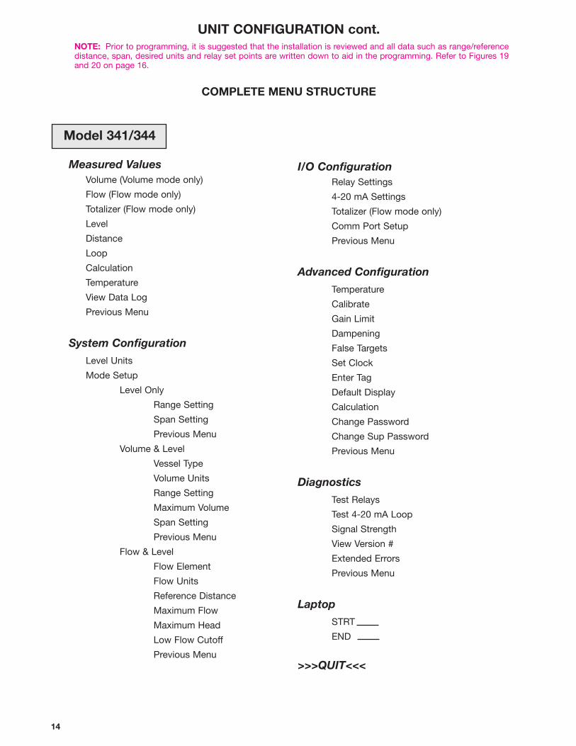
UNIT CONFIGURATION cont.NOTE: Prior to programming, it is suggested that the installation is reviewed and all data such as range/reference distance, span, desired units and relay set points are written down to aid in the programming. Refer to Figures 19and 20 on page 16.
Measured ValuesVolume (Volume mode only)
Flow (Flow mode only)
Totalizer (Flow mode only)
Level
Distance
Loop
Calculation
Temperature
View Data Log
Previous Menu
System Configuration
Level Units
Mode Setup
Level Only
Range Setting
Span Setting
Previous Menu
Volume & Level
Vessel Type
Volume Units
Range Setting
Maximum Volume
Span Setting
Previous Menu
Flow & Level
Flow Element
Flow Units
Reference Distance
Maximum Flow
Maximum Head
Low Flow Cutoff
Previous Menu
Model 341/344
I/O ConfigurationRelay Settings
4-20 mA Settings
Totalizer (Flow mode only)
Comm Port Setup
Previous Menu
Advanced Configuration
Temperature
Calibrate
Gain Limit
Dampening
False Targets
Set Clock
Enter Tag
Default Display
Calculation
Change Password
Change Sup Password
Previous Menu
Diagnostics
Test Relays
Test 4-20 mA Loop
Signal Strength
View Version #
Extended Errors
Previous Menu
Laptop
STRT
END
>>>QUIT<<<
COMPLETE MENU STRUCTURE
15
Level UnitsInchesFeetCentimetersMeters
System Config Menu - Level MeasurementThis menu is used to configure the main control parametersof the Model 341/344. This is also used for first time configu-ration of the unit. It is important to note that once in the System Config menu,you may scroll through the selections by using the UP orDOWN arrow. Once the desired selection is displayed, pressENT. The unit is capable of being configured in three differentmodes of operation.• Level Only
• Volume & Level
• Flow & Level
The menu layout for Level Measurement is shown below.
System Config - Level MeasurementLevel UnitsMode SetupRange SettingSpan SettingPrevious Menu
Measured Values
From the Default Display, press ENT to display MeasuredValues. Press the DOWN arrow to display System Config. Press ENT once again to enter System Config and to displayLevel Units. Press ENT to display the present units of meas-ure. Use the UP or DOWN arrow to scroll through units ofmeasurement. When the desired selection is displayed,press ENT to lock in value. Password? will be displayed ifthe selection has been changed and your chosen passwordmust be entered at this time. Press ENT to acknowledge anaccepted password and the unit will display the next menuitem - Mode Setup. Refer to page 12 on selection of a General or SupervisoryPassword. The factory default password is 0341. To changethis password use the Advanced Config menu. Refer to page27 for instruction.
Please refer to the above menu layout for the configura-tion instructions below.
Mode Set UpLevel OnlyVolume & LevelFlow & Level
With Mode Set Up on the display, press ENT to display thepresent mode. Scroll using the UP or DOWN arrows until thedesired mode is displayed. Press ENT when Level Only isdisplayed. If the mode selection has changed, a warning willappear: *** WARNING*** This mode change WILL erase ALL set-tings! Confirm change by pressing <9>.If the change is acknowledged after pressing <9>Password? will then be displayed. The password must beentered at this time. Press ENT to acknowledge the accept-ed password and the unit will display the next menu item -Range Setting.
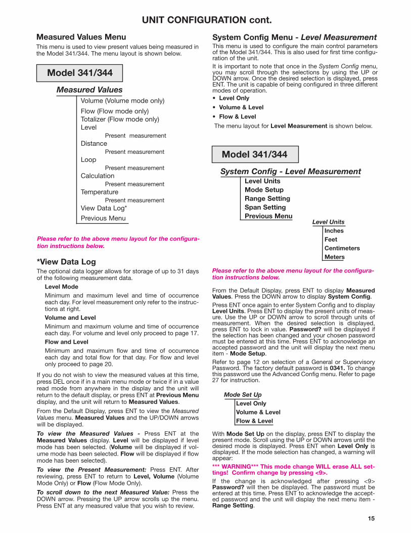
*View Data LogThe optional data logger allows for storage of up to 31 daysof the following measurement data.
Level ModeMinimum and maximum level and time of occurrence each day. For level measurement only refer to the instruc-tions at right.Volume and LevelMinimum and maximum volume and time of occurrence each day. For volume and level only proceed to page 17.Flow and LevelMinimum and maximum flow and time of occurrenceeach day and total flow for that day. For flow and levelonly proceed to page 20.
If you do not wish to view the measured values at this time,press DEL once if in a main menu mode or twice if in a valueread mode from anywhere in the display and the unit willreturn to the default display, or press ENT at Previous Menudisplay, and the unit will return to Measured Values.
From the Default Display, press ENT to view the MeasuredValues menu. Measured Values and the UP/DOWN arrowswill be displayed.
To view the Measured Values - Press ENT at theMeasured Values display. Level will be displayed if levelmode has been selected. (Volume will be displayed if vol-ume mode has been selected. Flow will be displayed if flowmode has been selected).
To view the Present Measurement: Press ENT. Afterreviewing, press ENT to return to Level, Volume (VolumeMode Only) or Flow (Flow Mode Only).
To scroll down to the next Measured Value: Press theDOWN arrow. Pressing the UP arrow scrolls up the menu.Press ENT at any measured value that you wish to review.
UNIT CONFIGURATION cont.
Measured ValuesVolume (Volume mode only)
Flow (Flow mode only)Totalizer (Flow mode only)Level
Present measurementDistance
Present measurementLoop
Present measurementCalculation
Present measurementTemperature
Present measurementView Data Log*
Previous Menu
Model 341/344
Please refer to the above menu layout for the configura-tion instructions below.
Measured Values MenuThis menu is used to view present values being measured inthe Model 341/344. The menu layout is shown below.
Model 341/344
16
Level Only
Span Setting
Manual Set
Auto Set
With Span Setting on the display, press ENT to displayManual Set. Use the UP or DOWN arrow to toggle betweenManual Set and Auto Set.
The Span Setting is the difference between the Range (lowlevel or zero) and the desired maximum level. Refer to Figure19. Maximum Span is the range value less the dead band,12" or 18" (305 or 460 mm). The operator is given the choiceof Manual Set or Auto Set.
Manual Set: The maximum level in the vessel must bemeasured or anticipated and entered at this time.
Auto Set: The 341/344 will actually measure the dis-tance between the transducer face and maximum level anticipated.
NOTE: The Manual Set mode for the Span Setting is the pre-ferred method of specifying this parameter.
When the desired span setting is displayed, press ENT toenable entry or display of the span values.
Enter or display the span values and press ENT. Password?will be displayed if the selection has been changed and yourchosen password must be entered at this time. Press ENTto acknowledge the accepted password and the unit will dis-play Previous Menu. Press ENT to return to the SystemConfiguration menu.
System Config Menu cont.
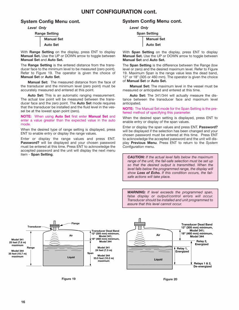
CAUTION: If the actual level falls below the maximumrange of the unit, the fail-safe selection must be set upso that the desired output is transmitted. When thelevel falls below the programmed range, the display willshow Loss of Echo. If this condition occurs, the fail-safe actions will take place.
Level Only
Range Setting
Manual Set
Auto Set
With Range Setting on the display, press ENT to displayManual Set. Use the UP or DOWN arrow to toggle betweenManual Set and Auto Set.
The Range Setting is the entered distance from the trans-ducer face to the minimum level to be measured (zero point).Refer to Figure 19. The operator is given the choice ofManual Set or Auto Set.
Manual Set: The measured distance from the face ofthe transducer and the minimum level (zero point) must beaccurately measured and entered at this point.
Auto Set: This is an automatic ranging measurement.The actual low point will be measured between the trans-ducer face and the zero point. The Auto Set mode requiresthat the transducer be installed and the fluid level in the ves-sel be at the lowest span point (zero).
NOTE: When using Auto Set first enter Manual Set andenter a value greater than the expected value in the automode.
When the desired type of range setting is displayed, pressENT to enable entry or display the range values.
Enter or display the range values and press ENT.Password? will be displayed and your chosen passwordmust be entered at this time. Press ENT to acknowledge theaccepted password and the unit will display the next menuitem - Span Setting.
Transducer
Air
Liquid
Transducer Dead Band12" (305 mm) minimum,
Model 341;18" (460 mm) minimum,
Model 344
Flange
Model 34125 feet (7.6 m)
maximum
Model 34435 feet (10.7 m)
maximum
Model 34124 feet (7.3 m)
Model 34433.5 feet (10.2 m)
maximum
Range
Span
UNIT CONFIGURATION cont.
System Config Menu cont.
Air
Liquid
Transducer Dead Band12" (305 mm) minimum,
Model 341;18" (460 mm) minimum,
Model 344
Relay 1,Energized
Relay 2,Energized
Relays 1 & 2,De-energized
Figure 19 Figure 20
WARNING: If level exceeds the programmed span,false display or output/control errors will occur.Transducer should be installed and unit programmed toassure that this level cannot occur.
17
System Config - Volume and Level Measurement
Level Units
Mode Setup
Vessel Type
Volume Units
Range Setting
Maximum Volume
Span Setting
Previous Menu
UNIT CONFIGURATION cont.
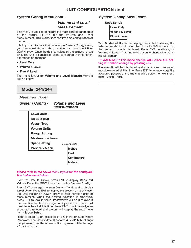
Measured Values
System Config Menu cont.
Volume and Level Measurement
This menu is used to configure the main control parametersof the Model 341/344 for the Volume and LevelMeasurement. This is also used for first time configuration ofthe unit.
It is important to note that once in the System Config menu,you may scroll through the selections by using the UP orDOWN arrow. Once the desired selection is displayed, pressENT. The unit is capable of being configured in three differ-ent modes of operation.
• Level Only
• Volume & Level
• Flow & Level
The menu layout for Volume and Level Measurement isshown below.
From the Default Display, press ENT to display MeasuredValues. Press the DOWN arrow to display System Config.
Press ENT once again to enter System Config and to displayLevel Units. Press ENT to display the present units of meas-ure. Use the UP or DOWN arrow to scroll through units ofmeasurement. When the desired selection is displayed,press ENT to lock in value. Password? will be displayed ifthe selection has been changed and your chosen passwordmust be entered at this time. Press ENT to acknowledge anaccepted password and the unit will display the next menuitem - Mode Setup.
Refer to page 12 on selection of a General or SupervisoryPassword. The factory default password is 0341. To changethis password use the Advanced Config menu. Refer to page27 for instruction.
Please refer to the above menu layout for the configura-tion instructions below.
Level Units
Inches
Feet
Centimeters
Meters
With Mode Set Up on the display, press ENT to display theselected mode. Scroll using the UP or DOWN arrows untilthe desired mode is displayed. Press ENT on display ofVolume & Level. If the mode selection is changed, a warn-ing will appear:
*** WARNING*** This mode change WILL erase ALL set-tings! Confirm change by pressing <9>.
Password? will be displayed and your chosen passwordmust be entered at this time. Press ENT to acknowledge theaccepted password and the unit will display the next menuitem - Vessel Type.
System Config Menu cont.Mode Set Up
Level Only
Volume & Level
Flow & Level
Model 341/344

18
With Vessel Type displayed, press ENT to display the pres-ent selection. Use the UP or DOWN arrow to scroll throughthe Vessel Type selections. When the desired vessel is dis-played, press ENT.
Enter the values needed to define the vessel parameters (ie.length, height, radius, end radius, cone, etc.), and press ENT.Refer to detailed vessel drawings.
NOTE: For Horiz/Elip tanks, when END is displayed, enterthe value for one end of vessel only.
Password? will be displayed and your chosen passwordmust be entered at this time. Press ENT to acknowledge theaccepted password and the unit will display the next menuitem - Volume Units refer to page 19.
System Config Menu cont.
UNIT CONFIGURATION cont.
Spherical
Rad
Ht
Volume and Level
Vessel Type
Horiz/Flat
Horiz/Elip
Horiz/Sphere
Verti/Flat
Verti/Conical
Spherical
Custom Table — Refer to pages 18 and 20
Len
Rad
Rad
Side View
Len
Horizontal/Spherical
Rad
Top View
Ht
Vertical/Flat
Vertical/Conical
Con
Rad
Top ViewSide View
Horizontal/Flat
Vessel Drawings
Len End
Rad
Side ViewHorizontal/Elliptical
19
UNIT CONFIGURATION cont.
System Config Menu cont.
Volume and Level
Span Setting
Manual Set
Auto Set
With Span Setting displayed, press ENT to display ManualSet. Use the UP or DOWN arrow to toggle between ManualSet and Auto Set. Refer to page 16 for explanation of Spanas well as Manual Set and Auto Set modes. When thedesired type of span setting is displayed, press ENT toenable entry of the span values.
Enter the span values and press ENT. Password? will bedisplayed and your chosen password must be entered atthis time. Press ENT to acknowledge the accepted pass-word and the unit will display the next menu item - PreviousMenu.
Press ENT to return to the System Configuration menu.
Volume and Level
Range Setting
Manual Set
Auto Set
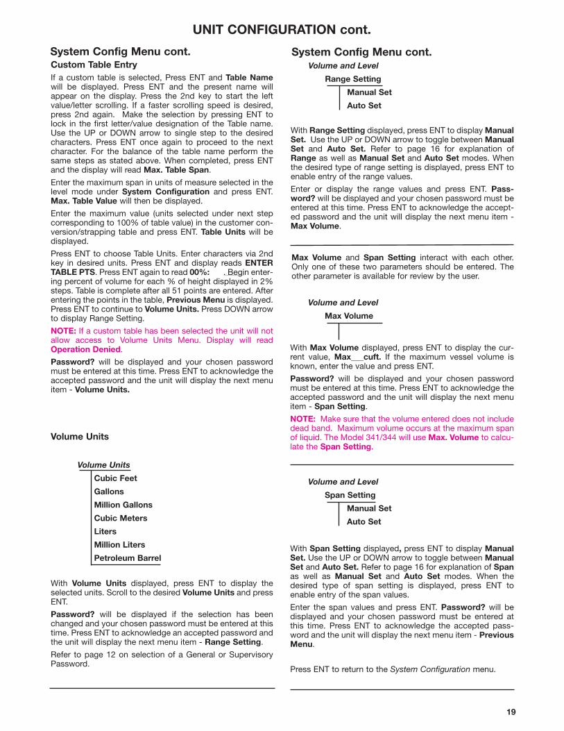
With Volume Units displayed, press ENT to display theselected units. Scroll to the desired Volume Units and pressENT.
Password? will be displayed if the selection has beenchanged and your chosen password must be entered at thistime. Press ENT to acknowledge an accepted password andthe unit will display the next menu item - Range Setting.
Refer to page 12 on selection of a General or SupervisoryPassword.
Volume Units
Cubic Feet
Gallons
Million Gallons
Cubic Meters
Liters
Million Liters
Petroleum Barrel
With Range Setting displayed, press ENT to display ManualSet. Use the UP or DOWN arrow to toggle between ManualSet and Auto Set. Refer to page 16 for explanation ofRange as well as Manual Set and Auto Set modes. Whenthe desired type of range setting is displayed, press ENT toenable entry of the range values.
Enter or display the range values and press ENT. Pass-word? will be displayed and your chosen password must beentered at this time. Press ENT to acknowledge the accept-ed password and the unit will display the next menu item -Max Volume.
Max Volume and Span Setting interact with each other.Only one of these two parameters should be entered. Theother parameter is available for review by the user.
Volume and Level
Max Volume
System Config Menu cont.Custom Table EntryIf a custom table is selected, Press ENT and Table Namewill be displayed. Press ENT and the present name willappear on the display. Press the 2nd key to start the leftvalue/letter scrolling. If a faster scrolling speed is desired,press 2nd again. Make the selection by pressing ENT tolock in the first letter/value designation of the Table name.Use the UP or DOWN arrow to single step to the desiredcharacters. Press ENT once again to proceed to the nextcharacter. For the balance of the table name perform thesame steps as stated above. When completed, press ENTand the display will read Max. Table Span.
Enter the maximum span in units of measure selected in thelevel mode under System Configuration and press ENT.Max. Table Value will then be displayed.
Enter the maximum value (units selected under next stepcorresponding to 100% of table value) in the customer con-version/strapping table and press ENT. Table Units will bedisplayed.
Press ENT to choose Table Units. Enter characters via 2ndkey in desired units. Press ENT and display reads ENTERTABLE PTS. Press ENT again to read 00%: . Begin enter-ing percent of volume for each % of height displayed in 2%steps. Table is complete after all 51 points are entered. Afterentering the points in the table, Previous Menu is displayed.Press ENT to continue to Volume Units. Press DOWN arrowto display Range Setting.
NOTE: If a custom table has been selected the unit will notallow access to Volume Units Menu. Display will readOperation Denied.
Password? will be displayed and your chosen passwordmust be entered at this time. Press ENT to acknowledge theaccepted password and the unit will display the next menuitem - Volume Units.
Volume Units
With Max Volume displayed, press ENT to display the cur-rent value, Max___cuft. If the maximum vessel volume isknown, enter the value and press ENT.
Password? will be displayed and your chosen passwordmust be entered at this time. Press ENT to acknowledge theaccepted password and the unit will display the next menuitem - Span Setting.
NOTE: Make sure that the volume entered does not includedead band. Maximum volume occurs at the maximum spanof liquid. The Model 341/344 will use Max. Volume to calcu-late the Span Setting.
20
Flow and Level
Flow Element
V-notch 22.5°
30°
45°
60°
90°
120°
Parshall 1"
2"
3"
6"
9"
12"
18"
24"
36"
48"
60"
72"
96"
120"
144"
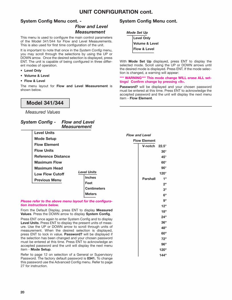
System Config - Flow and Level Measurement
Level Units
Mode Setup
Flow Element
Flow Units
Reference Distance
Maximum Flow
Maximum Head
Low Flow Cutoff
Previous Menu
With Mode Set Up displayed, press ENT to display theselected mode. Scroll using the UP or DOWN arrows untilthe desired mode is displayed. Press ENT. If the mode selec-tion is changed, a warning will appear:
*** WARNING*** This mode change WILL erase ALL set-tings! Confirm change by pressing <9>.
Password? will be displayed and your chosen passwordmust be entered at this time. Press ENT to acknowledge theaccepted password and the unit will display the next menuitem - Flow Element.
UNIT CONFIGURATION cont.
System Config Menu cont. -Flow and Level Measurement
This menu is used to configure the main control parametersof the Model 341/344 for Flow and Level Measurements.This is also used for first time configuration of the unit.
It is important to note that once in the System Config menu,you may scroll through the selections by using the UP orDOWN arrow. Once the desired selection is displayed, pressENT. The unit is capable of being configured in three differ-ent modes of operation.
• Level Only
• Volume & Level
• Flow & Level
The menu layout for Flow and Level Measurement isshown below.
Measured Values
Mode Set Up
Level Only
Volume & Level
Flow & Level
System Config Menu cont.
Level Units
Inches
Feet
Centimeters
Meters
Please refer to the above menu layout for the configura-tion instructions below.
From the Default Display, press ENT to display MeasuredValues. Press the DOWN arrow to display System Config.
Press ENT once again to enter System Config and to displayLevel Units. Press ENT to display the present units of meas-ure. Use the UP or DOWN arrow to scroll through units ofmeasurement. When the desired selection is displayed,press ENT to lock in value. Password? will be displayed ifthe selection has been changed and your chosen passwordmust be entered at this time. Press ENT to acknowledge anaccepted password and the unit will display the next menuitem - Mode Setup.
Refer to page 12 on selection of a General or SupervisoryPassword. The factory default password is 0341. To changethis password use the Advanced Config menu. Refer to page27 for instruction.
Model 341/344
21
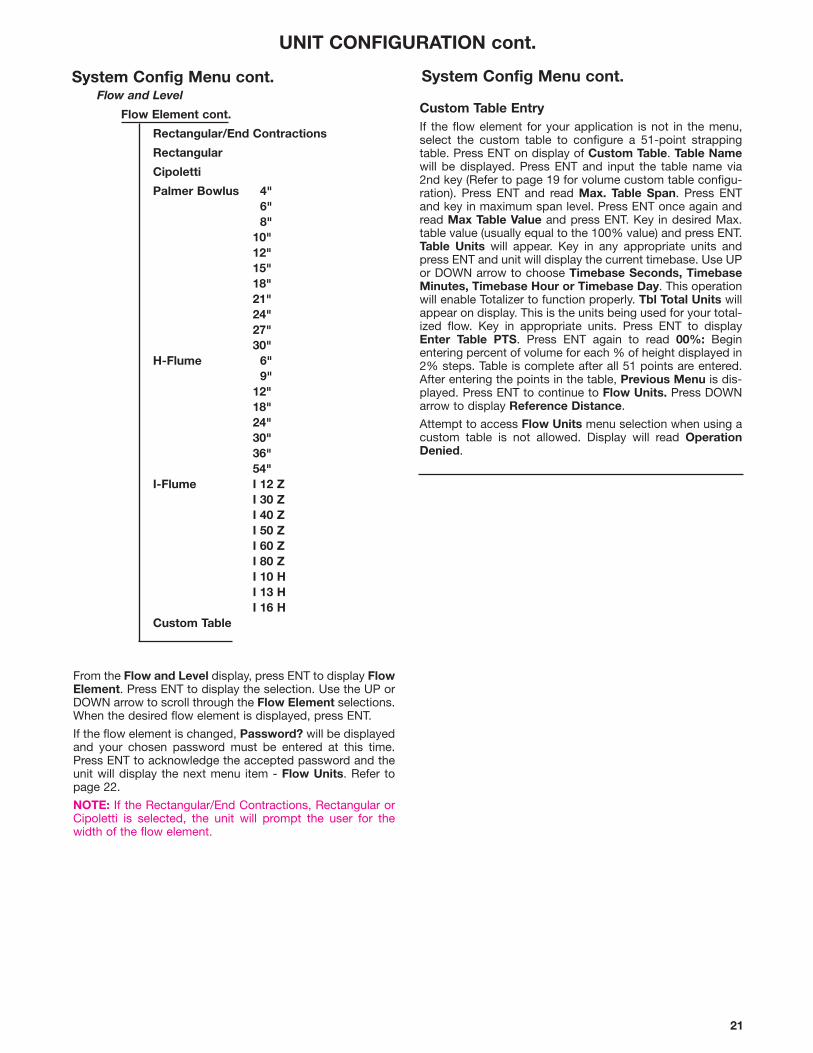
Flow and Level
Flow Element cont.
Rectangular/End Contractions
Rectangular
Cipoletti
Palmer Bowlus 4"6"8"
10"12"15"18"21"24"27"30"
H-Flume 6"9"
12"18"24"30"36"54"
I-Flume I 12 ZI 30 ZI 40 ZI 50 ZI 60 ZI 80 ZI 10 HI 13 HI 16 H
Custom Table
UNIT CONFIGURATION cont.
From the Flow and Level display, press ENT to display FlowElement. Press ENT to display the selection. Use the UP orDOWN arrow to scroll through the Flow Element selections.When the desired flow element is displayed, press ENT.
If the flow element is changed, Password? will be displayedand your chosen password must be entered at this time.Press ENT to acknowledge the accepted password and theunit will display the next menu item - Flow Units. Refer topage 22.
NOTE: If the Rectangular/End Contractions, Rectangular orCipoletti is selected, the unit will prompt the user for thewidth of the flow element.
Custom Table EntryIf the flow element for your application is not in the menu,select the custom table to configure a 51-point strappingtable. Press ENT on display of Custom Table. Table Namewill be displayed. Press ENT and input the table name via2nd key (Refer to page 19 for volume custom table configu-ration). Press ENT and read Max. Table Span. Press ENTand key in maximum span level. Press ENT once again andread Max Table Value and press ENT. Key in desired Max.table value (usually equal to the 100% value) and press ENT.Table Units will appear. Key in any appropriate units andpress ENT and unit will display the current timebase. Use UPor DOWN arrow to choose Timebase Seconds, TimebaseMinutes, Timebase Hour or Timebase Day. This operationwill enable Totalizer to function properly. Tbl Total Units willappear on display. This is the units being used for your total-ized flow. Key in appropriate units. Press ENT to displayEnter Table PTS. Press ENT again to read 00%: Beginentering percent of volume for each % of height displayed in2% steps. Table is complete after all 51 points are entered.After entering the points in the table, Previous Menu is dis-played. Press ENT to continue to Flow Units. Press DOWNarrow to display Reference Distance.
Attempt to access Flow Units menu selection when using acustom table is not allowed. Display will read OperationDenied.
System Config Menu cont. System Config Menu cont.
22
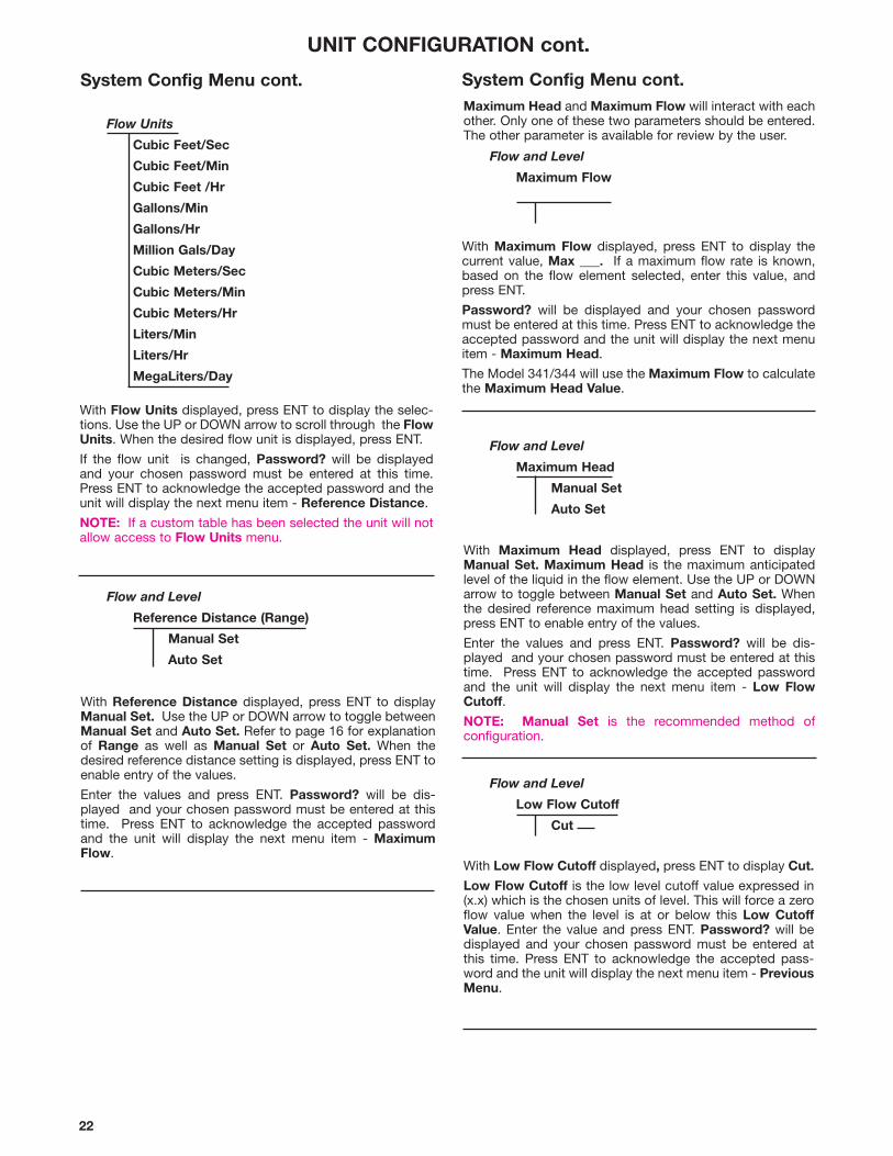
With Low Flow Cutoff displayed, press ENT to display Cut.
Low Flow Cutoff is the low level cutoff value expressed in(x.x) which is the chosen units of level. This will force a zeroflow value when the level is at or below this Low CutoffValue. Enter the value and press ENT. Password? will bedisplayed and your chosen password must be entered atthis time. Press ENT to acknowledge the accepted pass-word and the unit will display the next menu item - PreviousMenu.
Maximum Head and Maximum Flow will interact with eachother. Only one of these two parameters should be entered.The other parameter is available for review by the user.
Flow and Level
Maximum Flow
With Maximum Flow displayed, press ENT to display thecurrent value, Max ___. If a maximum flow rate is known,based on the flow element selected, enter this value, andpress ENT.
Password? will be displayed and your chosen passwordmust be entered at this time. Press ENT to acknowledge theaccepted password and the unit will display the next menuitem - Maximum Head.
The Model 341/344 will use the Maximum Flow to calculatethe Maximum Head Value.
Flow and Level
Maximum Head
Manual Set
Auto Set
With Maximum Head displayed, press ENT to displayManual Set. Maximum Head is the maximum anticipatedlevel of the liquid in the flow element. Use the UP or DOWNarrow to toggle between Manual Set and Auto Set. Whenthe desired reference maximum head setting is displayed,press ENT to enable entry of the values.
Enter the values and press ENT. Password? will be dis-played and your chosen password must be entered at thistime. Press ENT to acknowledge the accepted passwordand the unit will display the next menu item - Low FlowCutoff.
NOTE: Manual Set is the recommended method of configuration.
Flow and Level
Low Flow Cutoff
Cut
System Config Menu cont.
UNIT CONFIGURATION cont.
Flow Units
Cubic Feet/Sec
Cubic Feet/Min
Cubic Feet /Hr
Gallons/Min
Gallons/Hr
Million Gals/Day
Cubic Meters/Sec
Cubic Meters/Min
Cubic Meters/Hr
Liters/Min
Liters/Hr
MegaLiters/Day
Flow and Level
Reference Distance (Range)
Manual Set
Auto Set
With Flow Units displayed, press ENT to display the selec-tions. Use the UP or DOWN arrow to scroll through the FlowUnits. When the desired flow unit is displayed, press ENT.
If the flow unit is changed, Password? will be displayedand your chosen password must be entered at this time.Press ENT to acknowledge the accepted password and theunit will display the next menu item - Reference Distance.
NOTE: If a custom table has been selected the unit will notallow access to Flow Units menu.
With Reference Distance displayed, press ENT to displayManual Set. Use the UP or DOWN arrow to toggle betweenManual Set and Auto Set. Refer to page 16 for explanationof Range as well as Manual Set or Auto Set. When thedesired reference distance setting is displayed, press ENT toenable entry of the values.
Enter the values and press ENT. Password? will be dis-played and your chosen password must be entered at thistime. Press ENT to acknowledge the accepted passwordand the unit will display the next menu item - MaximumFlow.
System Config Menu cont.
23
UNIT CONFIGURATION cont.
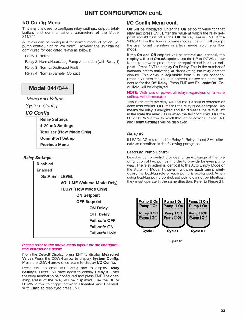
I/O Config MenuThis menu is used to configure relay settings, output, total-ization, and communications parameters of the Model341/344.
All relays can be configured for normal mode of action. (ie.pump control, high or low alarm). However the unit can beconfigured for dedicated relays as follows:
Relay 1 Normal
Relay 2 Normal/Lead/Lag Pump Alternation (with Relay 1)
Relay 3 Normal/Dedicated Fault
Relay 4 Normal/Sampler Contact
Measured Values
System Config
I/O ConfigRelay Settings
4-20 mA Settings
Totalizer (Flow Mode Only)
CommPort Set up
Previous Menu
Relay Settings
Disabled
Enabled
SetPoint LEVEL
VOLUME (Volume Mode Only)
FLOW (Flow Mode Only)
ON Setpoint
OFF Setpoint
ON Delay
OFF Delay
Fail-safe OFF
Fail-safe ON
Fail-safe Hold
Please refer to the above menu layout for the configura-tion instructions below.
From the Default Display, press ENT to display MeasuredValues.Press the DOWN arrow to display System Config.Press the DOWN arrow once again to display I/O Config.
Press ENT to enter I/O Config and to display RelaySettings. Press ENT once again to display Relay #. Enterthe relay number to be configured and press ENT. The oper-ating status of the relay will be displayed. Use the UP orDOWN arrow to toggle between Disabled and Enabled.With Enabled displayed press ENT.
Pump II OnPump I On
Pump II OffPump I Off
Pump I OnPump II On
Pump I OffPump II Off
Pump II OnPump I On
Pump II OffPump I Off
Cycle I Cycle II Cycle III
On will be displayed. Enter the On setpoint value for thatrelay and press ENT. Enter the value at which the relay set-point should turn off at the Off display. Press ENT. If the341/344 is in the flow or volume modes, the unit will promptthe user to set the relays in a level mode, volume or flowmode.
If the On and Off setpoint values entered are identical, thedisplay will read On>=Setpoint. Use the UP or DOWN arrowto toggle between greater than or equal to and less than set-point. Press ENT to display On Delay. This is the number ofseconds before activating or deactivating the relay contactclosure. This delay is adjustable from 1 to 120 seconds.Press ENT after the value is entered. Follow the same pro-cedure for the Off Delay. Press ENT and Fail-safe:Off, On,or Hold will be displayed.
NOTE: With loss of power, all relays regardless of fail-safesetting, will de-energize.
This is the state the relay will assume if a fault is detected orecho loss occurs. OFF means the relay is de-energized. Onmeans the relay is energized and Hold means the relay is leftin the state the relay was in when the fault occurred. Use theUP or DOWN arrow to scroll through selections. Press ENTand Relay Settings will be displayed.
Relay #2If LEAD/LAG is selected for Relay 2, Relays 1 and 2 will alter-nate as described in the following paragraph.
Lead/Lag Pump ControlLead/lag pump control provides for an exchange of the roleor function of two pumps in order to provide for even pumpwear. The relay action is identical to the Auto Empty Mode orthe Auto Fill Mode; however, following each pump shut-down, the lead/lag role of each pump is exchanged. Whenusing lead/lag pump control, set points cannot be identical;they must operate in the same direction. Refer to Figure 21.
I/O Config Menu cont.
Figure 21
Model 341/344
24
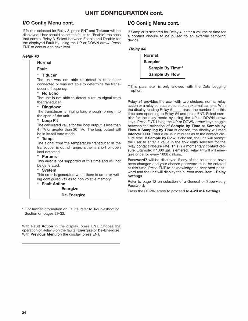
If Sampler is selected for Relay 4, enter a volume or time fora contact closure to be pulsed to an external samplingdevice.
**This parameter is only allowed with the Data Loggingoption.
Relay #4 provides the user with two choices, normal relayaction or a relay contact closure to an external sampler. Withthe display reading Relay # ____, press the number 4 at thistime corresponding to Relay #4 and press ENT. Select sam-pler for the relay mode by using the UP or DOWN arrowkeys. Press ENT. Using the UP or DOWN arrow keys, togglebetween the selection of Sample by Time or Sample byFlow. If Sampling by Time is chosen, the display will readInterval 0000. Enter a value in minutes as to the contact clo-sure time. If Sample by Flow is chosen, the unit will promptthe user to enter a value in the flow units selected for therelay contact closure rate. This is a momentary contact clo-sure. Example: If 1000 gal. is entered, Relay #4 will will ener-gize once for every 1000 gallons.
Password? will be displayed if any of the selections havebeen changed and your chosen password must be enteredat this time. Press ENT to acknowledge an accepted pass-word and the unit will display the current menu item - RelaySettings.
Refer to page 12 on selection of a General or SupervisoryPassword.
Press the DOWN arrow to proceed to 4-20 mA Settings.
UNIT CONFIGURATION cont.
I/O Config Menu cont.
Relay #3
Normal
Fault
* T'ducerThe unit was not able to detect a transducer connected or was not able to determine the trans-ducer's frequency.* No EchoThe unit is not able to detect a return signal fromthe transducer.* RingdownThe transducer is ringing long enough to ring intothe span of the unit.* Loop FltThe calculated value for the loop output is less than4 mA or greater than 20 mA. The loop output willbe in its fail-safe mode.* Temp.The signal from the temperature transducer in thetransducer is out of range. Either a short or openlead detected. * ParamsThis error is not supported at this time and will notbe generated. * SystemThis error is generated when there is an error writ-ing configured values to non volatile memory.* Fault Action
Energize
De-Energize
Relay #4
Normal
Sampler
Sample By Time**
Sample By Flow
I/O Config Menu cont.
With Fault Action in the display, press ENT. Choose theoperation of Relay 3 on the faults; Energize or De-Energize.With Previous Menu on the display, press ENT.
* For further information on Faults, refer to TroubleshootingSection on pages 29-32.
If fault is selected for Relay 3, press ENT and T'ducer will bedisplayed. User should select the faults to "Enable" the onesthat control Relay 3. Select between Enable and Disable forthe displayed Fault by using the UP or DOWN arrow. PressENT to continue to next item.

25
Comm Port Set Up
Laptop Rate
MagNet Rate
MagNet Addr
Previous Menu
4-20 mA Settings
4:
20:
Fail-safe: 4 mA
20 mA
22 mA
Hold
With Comm Port Set Up displayed, press ENT to displayLaptop Rate. Use the UP/DOWN arrow to scroll to thedesired rate for RS-232 communications and press ENT.
NOTE: The baud rate selected must match the baud ratesetting from the communications program of the laptopbeing used in the downloading scheme..
The unit will display MagNet Rate 300. Use the UP/DOWNarrow to scroll to the desired rate for RS-485 communica-tions. Press ENT at the desired rate and MagNet Addresswill be displayed. Enter the number assigned to the unit inthe field at which the MagNet software is to use as theaddress location and press ENT.
Password? will be displayed and your chosen passwordmust be entered at this time. Press ENT to acknowledge theaccepted password and the unit will display Comm Port SetUp. Use the DOWN arrow to scroll to Previous Menu andpress ENT. Press the DOWN arrow to scroll to the next menusection - Advanced Config.
With 4-20 mA Settings displayed, press ENT to displaySetpoint Level, Setpoint Flow or Setpoint Volume,depending on the mode that the unit is in. If level only isselected as the mode of operation, the display will read 4:___and 20: ___. In addition, if the Volume or Flow modes areselected, the 4 and 20 points can be entered as volume orflow units. Press ENT and 4: 0 is displayed. Enter the valuedesired for 4 mA and press ENT. 20:0 will be displayed. Enterthe value desired for the 20 mA and press ENT.
Loop Fail-Safe Settings
The Echotel 341/344 has a unique ability to calibrate its ana-log output anywhere inside its “system span” (refer to page16 for Span Setting). The analog (4-20 mA) signal can coverthe entire “system span” or just a small portion of it. If theactual level should move beyond the limits of the 4-20 mAspan, the analog output will hold the last value being gener-ated at the moment the unit went out of range.
NOTE: Relay fail-safe settings are totally independent of theanalog 4-20 mA fail-safe settings.
The analog output will assume predetermined values undercertain conditions. The conditions or events that will causethe unit to go into the fail-safe mode include echo loss, trans-ducer failure or ringdown error. The fail-safe output valuesmay be set as: 4 mA, 20 mA, 22 mA, or HOLD (last value).The 22 mA value is provided for use as an unmistakable indi-cation of a fault condition. The factory default setting for thisfeature will be HOLD.
To change the fail-safe setting, press the UP/DOWN arrowsand scroll through the four possible values. When the desiredvalue is displayed press ENT to select it. The unit will promptyou for a password before accepting the change. Enter theappropriate password (factory default is 0341) and pressENT. The display will then return to the menu selection 4-20mA Settings.
UNIT CONFIGURATION cont.
Totalizer (Flow Mode Only)
Hardware
Tot
Software
Tot
The selected display units will determine the totalizer units,i.e. if chosen units are gallons and multiplier is 100, every 100gallons the totalizer will advance once. Hardware totalizer isseven digits; software totalizer is six digits.
This is the weight of each count of flow increment shown onthe mechanical totalizer. With Totalizer displayed, press ENTto display Hardware. Press ENT and Tot 0 is displayed.Enter the value at which each digit changes based on thechosen units of flow and press ENT. The unit will displaySoftware. Press ENT and Tot 0 will be displayed. Enter thevalue desired at which the software totalizer changes eachincrement and press ENT.
Password? will be displayed and your chosen passwordmust be entered at this time. Press ENT to acknowledge theaccepted password and the unit will display Totalizer. Usethe DOWN arrow to scroll to display Comm Port Set Up.
NOTE: The hardware/software totalizing multiplier should bechosen so that at maximum value, the advance rate shouldnot exceed once per minute.
NOTE: If power to the unit is removed, Software Totalizer willreset to zero.
I/O Config Menu cont. I/O Config Menu cont.
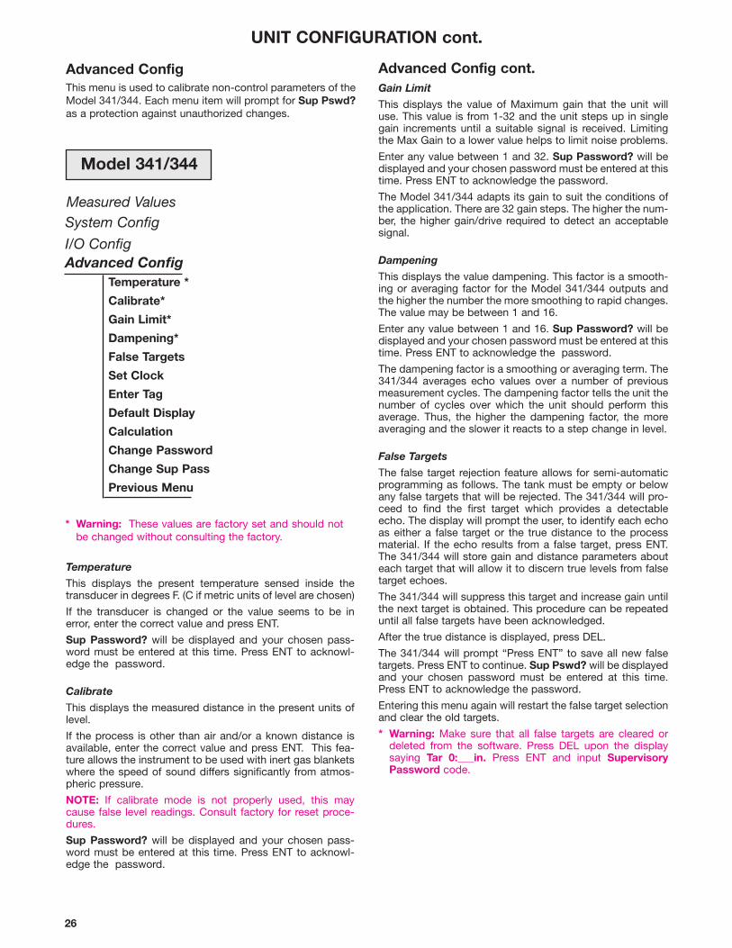
26
System Config
I/O ConfigAdvanced Config
Temperature *
Calibrate*
Gain Limit*
Dampening*
False Targets
Set Clock
Enter Tag
Default Display
Calculation
Change Password
Change Sup Pass
Previous Menu
* Warning: These values are factory set and should notbe changed without consulting the factory.
Measured Values
Advanced Config cont.Gain Limit
This displays the value of Maximum gain that the unit willuse. This value is from 1-32 and the unit steps up in singlegain increments until a suitable signal is received. Limitingthe Max Gain to a lower value helps to limit noise problems.
Enter any value between 1 and 32. Sup Password? will bedisplayed and your chosen password must be entered at thistime. Press ENT to acknowledge the password.
The Model 341/344 adapts its gain to suit the conditions ofthe application. There are 32 gain steps. The higher the num-ber, the higher gain/drive required to detect an acceptablesignal.
Dampening
This displays the value dampening. This factor is a smooth-ing or averaging factor for the Model 341/344 outputs andthe higher the number the more smoothing to rapid changes.The value may be between 1 and 16.
Enter any value between 1 and 16. Sup Password? will bedisplayed and your chosen password must be entered at thistime. Press ENT to acknowledge the password.
The dampening factor is a smoothing or averaging term. The341/344 averages echo values over a number of previousmeasurement cycles. The dampening factor tells the unit thenumber of cycles over which the unit should perform thisaverage. Thus, the higher the dampening factor, the moreaveraging and the slower it reacts to a step change in level.
False Targets
The false target rejection feature allows for semi-automaticprogramming as follows. The tank must be empty or belowany false targets that will be rejected. The 341/344 will pro-ceed to find the first target which provides a detectableecho. The display will prompt the user, to identify each echoas either a false target or the true distance to the processmaterial. If the echo results from a false target, press ENT.The 341/344 will store gain and distance parameters abouteach target that will allow it to discern true levels from falsetarget echoes.
The 341/344 will suppress this target and increase gain untilthe next target is obtained. This procedure can be repeateduntil all false targets have been acknowledged.
After the true distance is displayed, press DEL.
The 341/344 will prompt “Press ENT” to save all new falsetargets. Press ENT to continue. Sup Pswd? will be displayedand your chosen password must be entered at this time.Press ENT to acknowledge the password.
Entering this menu again will restart the false target selectionand clear the old targets.
* Warning: Make sure that all false targets are cleared ordeleted from the software. Press DEL upon the displaysaying Tar 0:___in. Press ENT and input SupervisoryPassword code.
Advanced ConfigThis menu is used to calibrate non-control parameters of theModel 341/344. Each menu item will prompt for Sup Pswd?as a protection against unauthorized changes.
UNIT CONFIGURATION cont.
Temperature
This displays the present temperature sensed inside thetransducer in degrees F. (C if metric units of level are chosen)
If the transducer is changed or the value seems to be inerror, enter the correct value and press ENT.
Sup Password? will be displayed and your chosen pass-word must be entered at this time. Press ENT to acknowl-edge the password.
Calibrate
This displays the measured distance in the present units oflevel.
If the process is other than air and/or a known distance isavailable, enter the correct value and press ENT. This fea-ture allows the instrument to be used with inert gas blanketswhere the speed of sound differs significantly from atmos-pheric pressure.
NOTE: If calibrate mode is not properly used, this maycause false level readings. Consult factory for reset proce-dures.
Sup Password? will be displayed and your chosen pass-word must be entered at this time. Press ENT to acknowl-edge the password.
Model 341/344

27
UNIT CONFIGURATION cont.
Advanced Config cont.Set Clock
This allows for setting or changing of the date and time. Thisis only available with the Data Logging option. Unit promptsfor:
Month? Date?Year?Hour? (24 hour format)Minute?
After entering these values, the unit prompts ENT to set andthen asks for the password.
Enter Tag
This menu shows the present Tag - Magnetrol.
If desired, this tag can be changed by using the UP orDOWN arrows to scan through characters and press ENT touse the character at that location in the Tag. Pressing the2nd key will start scrolling of the available characters. Whenclose to the desired character, press ENT and use arrows toreach desired character.
Default Display
This menu allows the operator to select the items to be dis-played during normal operation.The following items may betoggled Enabled/Disabled using the UP and DOWN arrow:
Level
Vol/Flow (Only when Volume or Flow mode is chosen)
Loop
Tag (Magnetrol)
Clock
Calc.
Totl.
The last menu item is Previous Menu. If any change wasmade in the default display, ENT at this point will cause theunit to prompt for the Sup Pswd.
Advanced Config cont.Calculation
Press ENT to display Existing Text Is. Press ENT again todisplay Text: ___ . Enter Text by using UP or DOWN arrowkeys and press ENT at each entry. Display will then readMult:. This is the multiplier used to show up in calculation.This value is multiplied by your level, flow or volume reading.
NOTE: The calculation is only for display purposes. Itdoes not affect the control relays or loop current output.
Change Password
Allows for a change of password. Requires the Sup Pswd.
Change Sup Password
Allows for a change of Sup Pswd. Requires the Sup Pswd.
Previous Menu
Returns to the previous menu, Advanced Config.
Press DOWN arrow to proceed to Diagnostics.
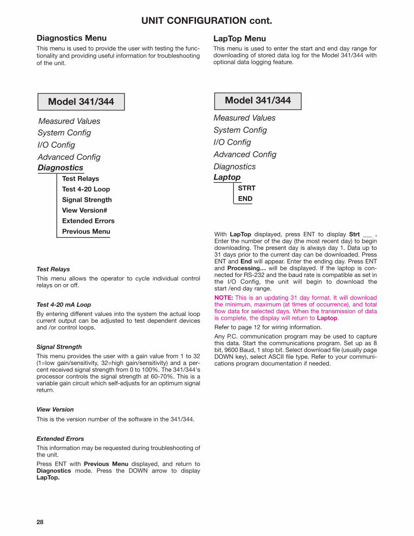
28
System Config
I/O Config
Advanced ConfigDiagnostics
Test Relays
Test 4-20 Loop
Signal Strength
View Version#
Extended Errors
Previous Menu
Measured Values
Test Relays
This menu allows the operator to cycle individual controlrelays on or off.
Test 4-20 mA Loop
By entering different values into the system the actual loopcurrent output can be adjusted to test dependent devicesand /or control loops.
Signal Strength
This menu provides the user with a gain value from 1 to 32(1=low gain/sensitivity, 32=high gain/sensitivity) and a per-cent received signal strength from 0 to 100%. The 341/344'sprocessor controls the signal strength at 60-70%. This is avariable gain circuit which self-adjusts for an optimum signalreturn.
View Version
This is the version number of the software in the 341/344.
Extended Errors
This information may be requested during troubleshooting ofthe unit.
Press ENT with Previous Menu displayed, and return toDiagnostics mode. Press the DOWN arrow to displayLapTop.
Diagnostics MenuThis menu is used to provide the user with testing the func-tionality and providing useful information for troubleshootingof the unit.
LapTop MenuThis menu is used to enter the start and end day range fordownloading of stored data log for the Model 341/344 withoptional data logging feature.
Measured Values
System Config
I/O Config
Advanced Config
DiagnosticsLaptop
STRT
END
With LapTop displayed, press ENT to display Strt ___ .Enter the number of the day (the most recent day) to begindownloading. The present day is always day 1. Data up to31 days prior to the current day can be downloaded. PressENT and End will appear. Enter the ending day. Press ENTand Processing… will be displayed. If the laptop is con-nected for RS-232 and the baud rate is compatible as set inthe I/O Config, the unit will begin to download thestart /end day range.
NOTE: This is an updating 31 day format. It will downloadthe minimum, maximum (at times of occurrence), and totalflow data for selected days. When the transmission of datais complete, the display will return to Laptop.
Refer to page 12 for wiring information.
Any P.C. communication program may be used to capturethis data. Start the communications program. Set up as 8bit, 9600 Baud, 1 stop bit. Select download file (usually pageDOWN key), select ASCII file type. Refer to your communi-cations program documentation if needed.
UNIT CONFIGURATION cont.
Model 341/344 Model 341/344
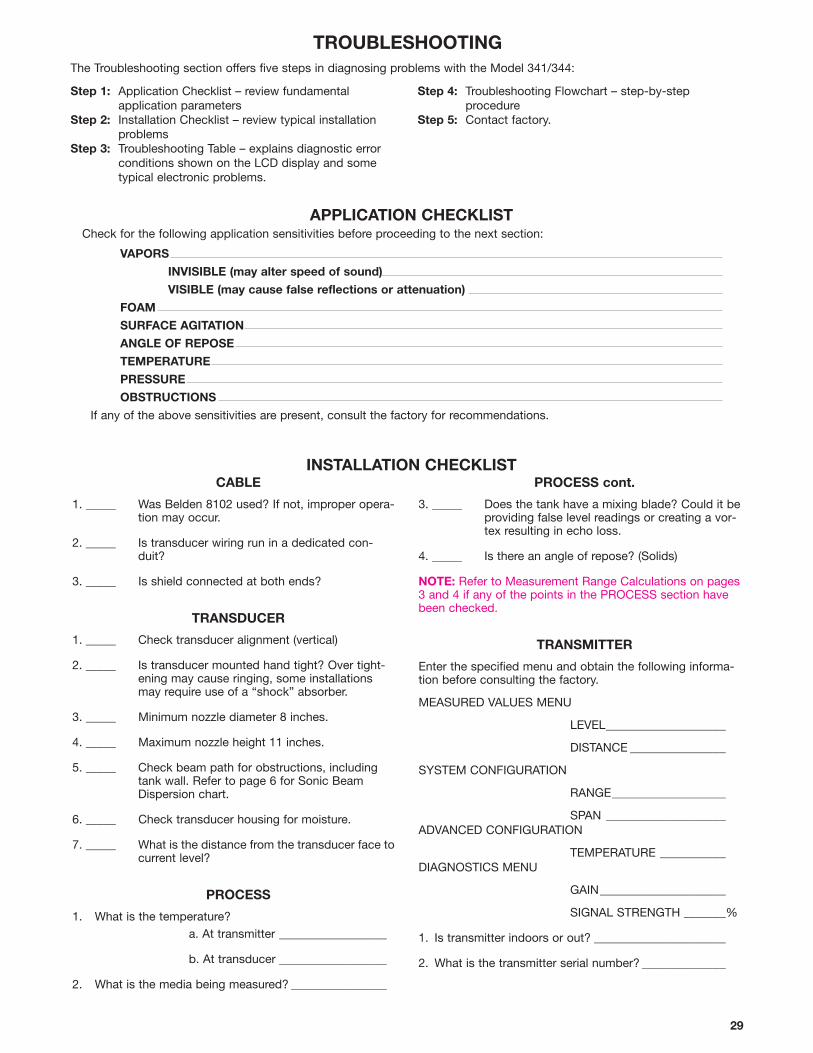
29
APPLICATION CHECKLISTCheck for the following application sensitivities before proceeding to the next section:
VAPORS
INVISIBLE (may alter speed of sound)
VISIBLE (may cause false reflections or attenuation)
FOAM
SURFACE AGITATION
ANGLE OF REPOSE
TEMPERATURE
PRESSURE
OBSTRUCTIONS
If any of the above sensitivities are present, consult the factory for recommendations.
TROUBLESHOOTING
CABLE
1. _____ Was Belden 8102 used? If not, improper opera-tion may occur.
2. _____ Is transducer wiring run in a dedicated con-duit?
3. _____ Is shield connected at both ends?
TRANSDUCER
1. _____ Check transducer alignment (vertical)
2. _____ Is transducer mounted hand tight? Over tight-ening may cause ringing, some installationsmay require use of a “shock” absorber.
3. _____ Minimum nozzle diameter 8 inches.
4. _____ Maximum nozzle height 11 inches.
5. _____ Check beam path for obstructions, including tank wall. Refer to page 6 for Sonic BeamDispersion chart.
6. _____ Check transducer housing for moisture.
7. _____ What is the distance from the transducer face tocurrent level?
PROCESS
1. What is the temperature?a. At transmitter __________________
b. At transducer __________________
2. What is the media being measured? ________________
PROCESS cont.
3. _____ Does the tank have a mixing blade? Could it beproviding false level readings or creating a vor-tex resulting in echo loss.
4. _____ Is there an angle of repose? (Solids)
NOTE: Refer to Measurement Range Calculations on pages3 and 4 if any of the points in the PROCESS section havebeen checked.
TRANSMITTER
Enter the specified menu and obtain the following informa-tion before consulting the factory.
MEASURED VALUES MENU
LEVEL____________________
DISTANCE ________________
SYSTEM CONFIGURATION
RANGE___________________
SPAN ____________________ADVANCED CONFIGURATION
TEMPERATURE ___________DIAGNOSTICS MENU
GAIN_____________________
SIGNAL STRENGTH _______%
1. Is transmitter indoors or out? ______________________
2. What is the transmitter serial number? ______________
INSTALLATION CHECKLIST
The Troubleshooting section offers five steps in diagnosing problems with the Model 341/344:
Step 1: Application Checklist – review fundamental application parameters
Step 2: Installation Checklist – review typical installationproblems
Step 3: Troubleshooting Table – explains diagnostic errorconditions shown on the LCD display and sometypical electronic problems.
Step 4: Troubleshooting Flowchart – step-by-step procedure
Step 5: Contact factory.
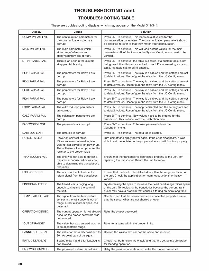
30
TROUBLESHOOTING cont.
These are troubleshooting displays which may appear on the Model 341/344.
Display Cause Solution
COMM PARAM FAIL The configuration parameters for Press ENT to continue. This loads default values for the the communications port are communication parameters. The communication parameters should corrupt. be checked to refer to that they match your configuration.
MAIN PARAM FAIL The main parameters which Press ENT to continue. This will load default values for the mainstore range/reference and parameters. All of the items in the System Config menu need to be span/headroom are corrupt. verified.
STRAP TABLE FAIL There is an error in the custom Press ENT to continue; the table is cleared. If a custom table is notstrapping table entry. being used, then this error can be ignored. If you are using a custom
table, the table has to be re-entered.
RLY1 PARAM FAIL The parameters for Relay 1 are Press ENT to continue. The relay is disabled and the settings are setcorrupt. to default values. Reconfigure the relay from the I/O Config menu.
RLY2 PARAM FAIL The parameters for Relay 2 are Press ENT to continue. The relay is disabled and the settings are setcorrupt. to default values. Reconfigure the relay from the I/O Config menu.
RLY3 PARAM FAIL The parameters for Relay 3 are Press ENT to continue. The relay is disabled and the settings are setcorrupt. to default values. Reconfigure the relay from the I/O Config menu.
RLY4 PARAM FAIL The parameters for Relay 4 are Press ENT to continue. The relay is disabled and the settings are setcorrupt. to default values. Reconfigure the relay from the I/O Config menu.
LOOP PARAM FAIL The 4–20 mA loop parameters Press ENT to continue. The loop is disabled and the settings are setare corrupt. to default values. Reconfigure the relay from the I/O Config menu.
CALC PARAM FAIL The calculation parameters are Press ENT to continue. New values need to be entered for thecorrupt. calculation. This is done from the Calibration menu.
PASSWORD LOST The passwords are corrupt. Press ENT to continue. Enter new passwords from theCalibration menu.
DATA LOG LOST The data log is corrupt. Press ENT to continue. The data log is cleared.
P.O.S.T. FAILED Power on self test failed. Turn unit off and apply power again. If the error disappears, it wasMicroprocessor internal register able to set the register to the proper value and will function properly.was not set correctly on power up.The software will attempt to set theregister to the proper value
TRANSDUCER FAIL The unit was not able to detect a Ensure that the transducer is connected properly to the unit. Try transducer connected or was not replacing the transducer. Return the unit for repair.able to determine the transducer'sfrequency.
LOSS OF ECHO The unit is not able to detect a Ensure that the level to be detected is within the range and span ofreturn signal from the transducer. the unit. Check the application for foam, obstructions, or heavy
vapors.
RINGDOWN ERROR The transducer is ringing long Try decreasing the span to increase the dead band (range minus span)enough to ring into the span of of the unit. Try replacing the transducer because the current trans-the unit. ducer may have a problem that causes it to ring an extra long time.
TEMPERATURE FAULT The signal from the temperature Check to see that the sensor wires are connected properly. Ensure sensor in the transducer is out of that the sensor wires are not shorted or open.range. Either a short or open leaddetected.
OPERATION DENIED The current operation is not allowed Retry the proper password.because the proper password wasnot entered.
“OUT OF RANGE” The value that was entered was not Re-enter a value within the proper limits.in an acceptable range.
CANNOT BE EQUAL The value for the 4 mA point and the Choose the values that are not the same and re-enter.20 mA point cannot be equal.
INVALID LEAD/LAG Setting relay 1 and 2 for lead/lag is Check that both relays are enable and that the set points are propernot allowed. for lead/lag operation.
PASSWORD INVALID The password entered is not valid. Retry the previous operation and enter the proper password.
TROUBLESHOOTING TABLE
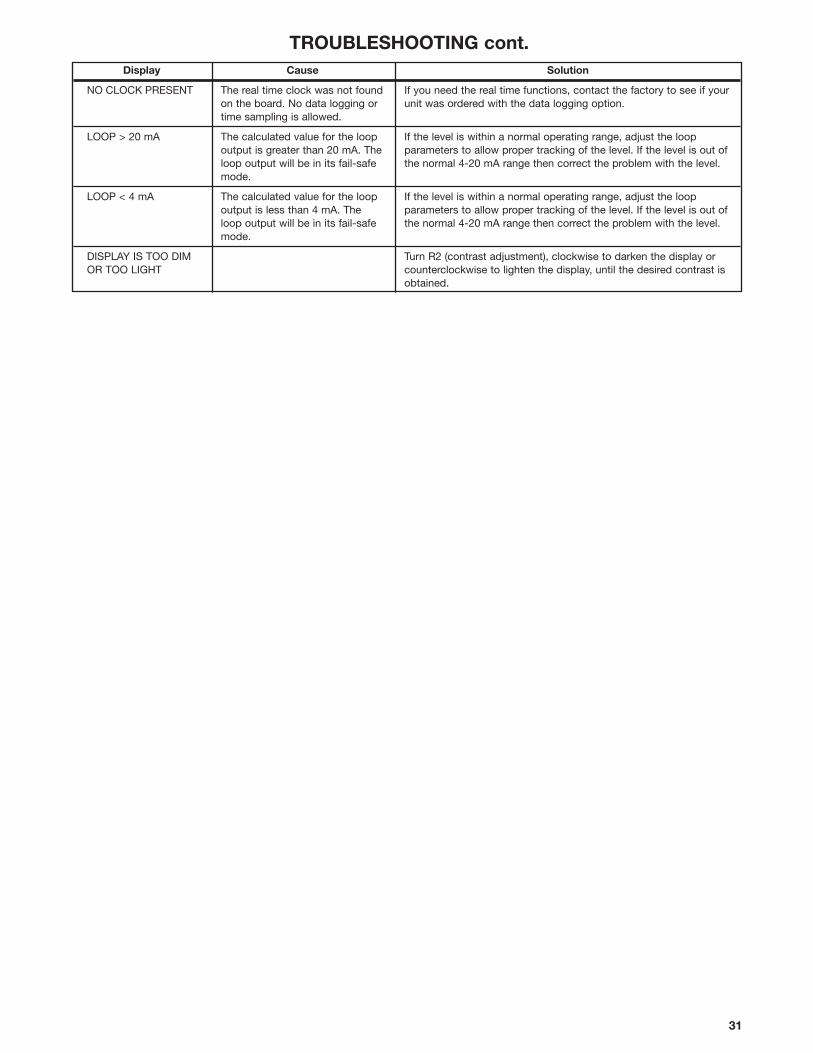
31
TROUBLESHOOTING cont. Display Cause Solution
NO CLOCK PRESENT The real time clock was not found If you need the real time functions, contact the factory to see if youron the board. No data logging or unit was ordered with the data logging option.time sampling is allowed.
LOOP > 20 mA The calculated value for the loop If the level is within a normal operating range, adjust the loop output is greater than 20 mA. The parameters to allow proper tracking of the level. If the level is out of loop output will be in its fail-safe the normal 4-20 mA range then correct the problem with the level.mode.
LOOP < 4 mA The calculated value for the loop If the level is within a normal operating range, adjust the loop output is less than 4 mA. The parameters to allow proper tracking of the level. If the level is out of loop output will be in its fail-safe the normal 4-20 mA range then correct the problem with the level.mode.
DISPLAY IS TOO DIM Turn R2 (contrast adjustment), clockwise to darken the display orOR TOO LIGHT counterclockwise to lighten the display, until the desired contrast is
obtained.
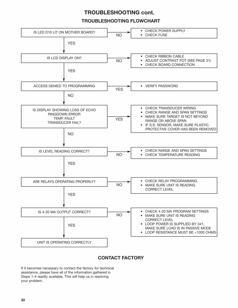
32
TROUBLESHOOTING cont.
TROUBLESHOOTING FLOWCHART
IS LED D10 LIT ON MOTHER BOARD? • CHECK POWER SUPPLY• CHECK FUSE
IS LCD DISPLAY ON? • CHECK RIBBON CABLE• ADJUST CONTRAST POT (SEE PAGE 31)• CHECK BOARD CONNECTION
ACCESS DENIED TO PROGRAMMING • VERIFY PASSWORD
IS DISPLAY SHOWING LOSS OF ECHORINGDOWN ERROR
TEMP. FAULTTRANSDUCER FAIL?
• CHECK TRANSDUCER WIRING• CHECK RANGE AND SPAN SETTINGS• MAKE SURE TARGET IS NOT BEYOND
RANGE OR ABOVE SPAN• IF S.S. SENSOR, MAKE SURE PLASTIC
PROTECTIVE COVER HAS BEEN REMOVED
IS LEVEL READING CORRECT? • CHECK RANGE AND SPAN SETTINGS• CHECK TEMPERATURE READING
ARE RELAYS OPERATING PROPERLY? • CHECK RELAY PROGRAMMING• MAKE SURE UNIT IS READING
CORRECT LEVEL
IS 4-20 MA OUTPUT CORRECT? • CHECK 4-20 MA PROGRAM SETTINGS• MAKE SURE UNIT IS READING
CORRECT LEVEL• LOOP POWER IS SUPPLIED BY 341,
MAKE SURE LOAD IS IN PASSIVE MODE• LOOP RESISTANCE MUST BE <1000 OHMS
UNIT IS OPERATING CORRECTLY
CONTACT FACTORY
If it becomes necessary to contact the factory for technicalassistance, please have all of the information gathered inSteps 1-4 readily available. This will help us in resolving your problem.
YES
YES
NO
NO
YES
YES
YES
NO
NO
NO
NO
NO
YES
YES
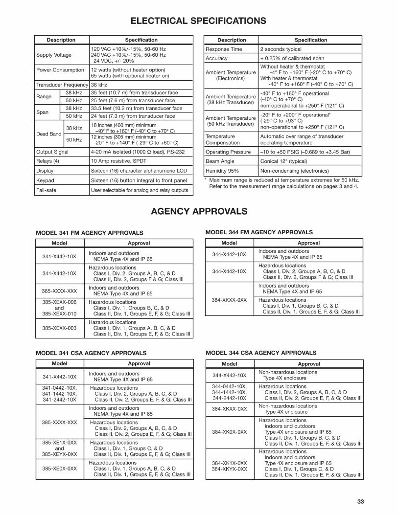
33
AGENCY APPROVALS
Description Specification
120 VAC +10%/-15%, 50-60 HzSupply Voltage 240 VAC +10%/-15%, 50-60 Hz
24 VDC, +/- 20%
Power Consumption 12 watts (without heater option)65 watts (with optional heater on)
Transducer Frequency 38 kHz
Range38 kHz 35 feet (10.7 m) from transducer face
50 kHz 25 feet (7.6 m) from transducer face
Span38 kHz 33.5 feet (10.2 m) from transducer face
50 kHz 24 feet (7.3 m) from transducer face
38 kHz 18 inches (460 mm) minimum
Dead Band -40° F to +160° F (-40° C to +70° C)
50 kHz 12 inches (305 mm) minimum-20° F to +140° F (-29° C to +60° C)
Output Signal 4-20 mA isolated (1000 Ω load), RS-232
Relays (4) 10 Amp resistive, SPDT
Display Sixteen (16) character alphanumeric LCD
Keypad Sixteen (16) button integral to front panel
Fail-safe User selectable for analog and relay outputs
Description Specification
Response Time 2 seconds typical
Accuracy ± 0.25% of calibrated span
Without heater & thermostatAmbient Temperature -4° F to +160° F (-20° C to +70° C)
(Electronics) With heater & thermostat-40° F to +160° F (-40° C to +70° C)
Ambient Temperature-40° F to +160° F operational(-40° C to +70° C)
(38 kHz Transducer)non-operational to +250° F (121° C)
Ambient Temperature-20° F to +200° F operational*(-29° C to +93° C)
(50 kHz Transducer)non-operational to +250° F (121° C)
Temperature Automatic over range of transducerCompensation operating temperature
Operating Pressure –10 to +50 PSIG (–0.689 to +3.45 Bar)
Beam Angle Conical 12° (typical)
Humidity 95% Non-condensing (electronics)
ELECTRICAL SPECIFICATIONS
MODEL 344 FM AGENCY APPROVALS
MODEL 344 CSA AGENCY APPROVALS
Model Approval
341-X442-10XIndoors and outdoors
NEMA Type 4X and IP 65
Hazardous locations341-X442-10X Class I, Div. 2, Groups A, B, C, & D
Class II, Div. 2, Groups F & G; Class III
385-XXXX-XXXIndoors and outdoors
NEMA Type 4X and IP 65
385-XEXX-006 Hazardous locationsand Class I, Div. 1, Groups B, C, & D
385-XEXX-010 Class II, Div. 1, Groups E, F, & G; Class III
Hazardous locations385-XEXX-003 Class I, Div. 1, Groups A, B, C, & D
Class II, Div. 1, Groups E, F, & G; Class III
MODEL 341 FM AGENCY APPROVALS
MODEL 341 CSA AGENCY APPROVALS
* Maximum range is reduced at temperature extremes for 50 kHz.Refer to the measurement range calculations on pages 3 and 4.
Model Approval
341-X442-10XIndoors and outdoors
NEMA Type 4X and IP 65
341-0442-10X, Hazardous locations341-1442-10X, Class I, Div. 2, Groups A, B, C, & D341-2442-10X Class II, Div. 2, Groups E, F, & G; Class III
Indoors and outdoorsNEMA Type 4X and IP 65
385-XXXX-XXX Hazardous locationsClass I, Div. 2, Groups A, B, C, & DClass II, Div. 2, Groups E, F, & G; Class III
385-XE1X-0XX Hazardous locationsand Class I, Div. 1, Groups C, & D
385-XEYX-0XX Class II, Div. 1, Groups E, F, & G; Class III
Hazardous locations385-XE0X-0XX Class I, Div. 1, Groups A, B, C, & D
Class II, Div. 1, Groups E, F, & G; Class III
Model Approval
344-X442-10XIndoors and outdoors
NEMA Type 4X and IP 65
Hazardous locations344-X442-10X Class I, Div. 2, Groups A, B, C, & D
Class II, Div. 2, Groups F & G; Class III
Indoors and outdoorsNEMA Type 4X and IP 65
384-XKXX-0XX Hazardous locationsClass I, Div. 1, Groups B, C, & DClass II, Div. 1, Groups E, F, & G; Class III
Model Approval
344-X442-10XNon-hazardous locations
Type 4X enclosure
344-0442-10X, Hazardous locations344-1442-10X, Class I, Div. 2, Groups A, B, C, & D344-2442-10X Class II, Div. 2, Groups E, F, & G; Class III
384-XKXX-0XX Non-hazardous locationsType 4X enclosure
Hazardous locationsIndoors and outdoors
384-XK0X-0XX Type 4X enclosure and IP 65Class I, Div. 1, Groups B, C, & DClass II, Div. 1, Groups E, F, & G; Class III
Hazardous locationsIndoors and outdoors
384-XK1X-0XX Type 4X enclosure and IP 65384-XKYX-0XX Class I, Div. 1, Groups C, & D
Class II, Div. 1, Groups E, F, & G; Class III
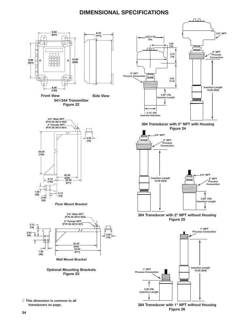
34
DIMENSIONAL SPECIFICATIONS
3.00(76)
29.00(736)
1.50(38) 3.12
(79)
6.12(155)
20.50(520)22.50(571)
2.00(50)
2" Female NPT(P/N 36-3813-001)
3/4" Male NPT(P/N 36-3813-002)
3/4" Male NPT(P/N 36-3812-002)
20.50(520)22.50(571)
3.00(76)
1.50(38)
2.00(50)
3.12(79)
2" Female NPT(P/N 36-3812-001)
Floor Mount Bracket
Wall Mount Bracket
9.50(241)
9.50(241)
13.00(330)
6.00(152)
6.75(171)
1" NPTProcess Connection
3.00 (76)Insertion Length
Front View
384 Transducer with 1" NPT without HousingFigure 26
2" NPTProcess Connection
3.00" (76)Insertion Length
4.63 (118)Dia.
3.00(76)
2.75(70)
4.50(114)
➀ 2.12" (54)Insertion Diameter
2" NPTProcess
Connection
3/4" NPT
Insertion Length10.00 (254)
Insertion Length10.00 (254)
1" NPTProcess Connection
2" NPTProcess
Connection
Insertion Length10.00 (254)
3/4" NPT
2" NPTProcess
Connection
3.00" (76)Insertion Length
3/4" NPT
384 Transducer with 2" NPT without HousingFigure 25
Side View341/344 Transmitter
Figure 22
Optional Mounting BracketsFigure 23
384 Transducer with 2" NPT with HousingFigure 24
➀ This dimension is common to alltransducers on page.
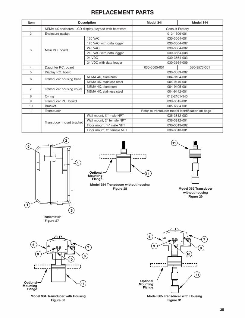
Model 384 Transducer without housingFigure 28
Model 384 Transducer with HousingFigure 30
TransmitterFigure 27
OptionalMounting
Flange
11
OptionalMounting
Flange
108
7
9
6
11
1
5
3
4
2
11
OptionalMounting
Flange
10
8
7
9
6
11
Model 385 Transducer with HousingFigure 31
Model 385 Transducer without housing
Figure 29
REPLACEMENT PARTS
35
Item Description Model 341 Model 344
1 NEMA 4X enclosure, LCD display, keypad with hardware Consult Factory
2 Enclosure gasket 012-1606-001
120 VAC 030-3564-001
120 VAC with data logger 030-3564-007
3 Main P.C. board240 VAC 030-3564-002
240 VAC with data logger 030-3564-008
24 VDC 030-3564-003
24 VDC with data logger 030-3564-009
4 Daughter P.C. board 030-3565-001 030-3573-001
5 Display P.C. board 030-3539-002
6 Transducer housing baseNEMA 4X, aluminum 004-9104-001
NEMA 4X, stainless steel 004-9140-001
7 Transducer housing coverNEMA 4X, aluminum 004-9105-001
NEMA 4X, stainless steel 004-9142-001
8 O-ring 012-2101-345
9 Transducer P.C. board 030-3515-001
10 Bracket 005-6634-001
11 Transducer Refer to transducer model identification on page 1
Wall mount, 3⁄4" male NPT 036-3812-002
Transducer mount bracketWall mount, 2" female NPT 036-3812-001
Floor mount, 3⁄4" male NPT 036-3813-002
Floor mount, 2" female NPT 036-3813-001
IMPORTANT
5300 Belmont Road • Downers Grove, Illinois 60515-4499 • 630-969-4000 • Fax 630-969-9489 • www.magnetrol.com6291 Dorman Road • Mississauga, Ontario L4V-1H2 • 905-678-2720 • Fax 905-678-7407Heikenstraat 6 • B 9240 Zele, Belgium • 052 45.11.11 • Telex 25944 • Fax 052 45.09.93Regent Business Ctr., Jubilee Rd. • Burgess Hill, Sussex RH15 9TL U.K. • 01444-871313 • Fax 01444-871317
5300 Belmont Road • Downers Grove, Illinois 60515-4499 • 630-969-4028 • Fax 630-969-9489 • www.sticontrols.com
©2000 Magnetrol International, Incorporated. All rights reserved. Printed in the USA.Magnetrol and Magnetrol logotype are registered trademarks of Magnetrol International.STI and STI logotype are registered trademarks of Magnetrol International.
Performance specifications are effective with date of issue and are subject to change without notice.The brand and product names contained within this document are trademarks or registered trademarks of their respective holders.
SERVICE POLICY
Owners of Magnetrol/STI controls may request the return ofa control or any part of a control for complete rebuilding orreplacement. They will be rebuilt or replaced promptly.Controls returned under our service policy must be returnedby Prepaid transportation. Magnetrol/STI will repair orreplace the control at no cost to the purchaser (or owner)other than transportation if:
1. Returned within the warranty period; and2. The factory inspection finds the cause of the claim to
be covered under the warranty.
If the trouble is the result of conditions beyond our control;or, is NOT covered by the warranty, there will be charges forlabor and the parts required to rebuild or replace the equip-ment.
In some cases it may be expedient to ship replacementparts; or, in extreme cases a complete new control, toreplace the original equipment before it is returned. If this isdesired, notify the factory of both the model and serial num-bers of the control to be replaced. In such cases, credit forthe materials returned will be determined on the basis of theapplicability of our warranty.
No claims for misapplication, labor, direct or consequentialdamage will be allowed.
RETURN MATERIAL PROCEDURE
So that we may efficiently process any materials that arereturned, it is essential that a “Return Material Authorization”(RMA) number be obtained from the factory, prior to thematerial's return. This is available through Magnetrol/STI'slocal representative or by contacting the factory. Pleasesupply the following information:
1. Company Name2. Description of Material3. Serial Number4. Reason for Return5. Application
Any unit that was used in a process must be properlycleaned in accordance with OSHA standards, before it isreturned to the factory.
A Material Safety Data Sheet (MSDS) must accompanymaterial that was used in any media.
All shipments returned to the factory must be by prepaidtransportation.
All replacements will be shipped F.O.B. factory.
NOTE: See Electrostatic Discharge Handling Procedure onpage 9.
ASSURED QUALITY & SERVICE COST LESS
PRODUCT WARRANTY
All Magnetrol/STI electronic level and flow controls are war-ranted free of defects in materials or workmanship for onefull year from the date of original factory shipment.
If returned within the warranty period; and, upon factoryinspection of the control, the cause of the claim isdetermined to be covered under the warranty; then,Magnetrol/STI will repair or replace the control at no cost tothe purchaser (or owner) other than transportation.
Magnetrol/STI shall not be liable for misapplication, laborclaims, direct or consequential damage or expense arisingfrom the installation or use of equipment. There are no otherwarranties expressed or implied, except special writtenwarranties covering some Magnetrol/STI products.
QUALITY ASSURANCE
The quality assurance system in place atMagnetrol/STI guarantees the highestlevel of quality throughout the company.Magnetrol/STI is committed to providingfull customer satisfaction both in qualityproducts and quality service.
Magnetrol’s quality assurance system is registered to ISO9001 affirming its commitment to known internationalquality standards providing the strongest assurance ofproduct/service quality available.
LOW VOLTAGE DIRECTIVE
For use in Category II installations. If equipment is used in amanner not specified by manufacturer, protection providedby equipment may be impaired.
BULLETIN: 51-629.4(Software version 2.0)EFFECTIVE: January 2000SUPERSEDES: November 1998


![EIN Point1Aenderung - Startseite...L eon h crd-Hegwe' '__þ6_C MD au. Die . Anderun« b-Getzet Für das Re und re neue soda O entstehen. F] 341, 3" 72, 341/3, 34: '5, 344/1, 344/3,](https://img.pdfslide.net/doc/110x75/60e4e97b532ad673c425bcf5/ein-point1aenderung-startseite-l-eon-h-crd-hegwe-6c-md-au-die-anderun.jpg)