Embed Size (px)
Citation preview

Read through the safety information andoperating instructions carefully beforeusing your Waterous Fire Pump.
Illustrations1. Component Location 2. . . . . . . . . . . . . . . . . . . . . . . . . 2. Electric Auto Sync Control Panel 3. . . . . . . . . . . . . . . 3. Oil Cooler Drain Locations 8. . . . . . . . . . . . . . . . . . . . 4. Pneumatic Clutch 8. . . . . . . . . . . . . . . . . . . . . . . . . . . . 5. Air Control Circuit / Air Inlet Trim Valve / Balance
Trim Valve 9. . . . . . . . . . . . . . . . . . . . . . . . . . . . . . . . . .
Table of ContentsSafety Information 1. . . . . . . . . . . . . . . . . . . . . . . . . . . . . . General Description 2. . . . . . . . . . . . . . . . . . . . . . . . . . . . General Information 3. . . . . . . . . . . . . . . . . . . . . . . . . . . . Electric Auto Sync Control Panel 3. . . . . . . . . . . . . . . . . . .
Unload / Fixed / Auto Control Switch 3. . . . . . . . . . . . . . Unload Control Valve 3. . . . . . . . . . . . . . . . . . . . . . . . . . .
CAFS Nozzle / Flow Rate / Hose Combinations 3. . . . . . Nozzles 3. . . . . . . . . . . . . . . . . . . . . . . . . . . . . . . . . . . . . . Foam Concentrate Ratios 3. . . . . . . . . . . . . . . . . . . . . . . Hose 3. . . . . . . . . . . . . . . . . . . . . . . . . . . . . . . . . . . . . . . . .
Operation 4. . . . . . . . . . . . . . . . . . . . . . . . . . . . . . . . . . . . . . Water Pumping Operations 4. . . . . . . . . . . . . . . . . . . . . . . Foam Solution Operations 4. . . . . . . . . . . . . . . . . . . . . . . . Compressed Air Foam Operations 5. . . . . . . . . . . . . . . . . Compressed Air Only 5. . . . . . . . . . . . . . . . . . . . . . . . . . . . Shut Down Procedure 6. . . . . . . . . . . . . . . . . . . . . . . . . . Compressed Air Foam Operations 6. . . . . . . . . . . . . . . . . Compressed Auto Shut Down (Overheat) 6. . . . . . . . . Service and Maintenance 7. . . . . . . . . . . . . . . . . . . . . . . Calibration − Control Air Circuit 8. . . . . . . . . . . . . . . . . CAFS Customer’s Troubleshooting Guide 10. . . . . . .
Eclipse CAFSystem with Electric Auto−Sync Operation
Waterous Company 125 Hardman Avenue South, South St. Paul, Minnesota 55075 USA (651) 450−5000Instructions subject to change without notice.
Visit us at www.waterousco.com
Section
2121Form No.
F−1031Issue Date
02/01/05Rev. Date
09/23/05
Eclipse � CAFSystemwith Electric Auto−Sync
Operation and Maintenance

F−1031, Section 2121 Page 1 of 12REV: 09/23/05
Safety Information
Read through the safety information and operating instructions before using your Waterous Fire Pump.
WARNING!
Death or serious personal injury might occur if properoperating procedures are not followed. The pump op-erator, as well as individuals connecting supply or dis-charge hoses to the apparatus must be familiar withthese pump operating instructions as well as otheroperating instructions and manuals for the apparatus,water hydraulics and component limitation.
WARNING!
Pressure Hazard. May result in personal injury.
Prior to connection or removal of hoses, caps or otherclosures with pump intake or pump discharge connec-tions, relieve pressure by opening drains or bleedervalves. Bleeder valves should also be used while fillinga hose connected to an intake with water.
WARNING!
Scalding Water Hazard. May result in serious burns.
When operating the pump, be sure to open at leastone discharge valve slightly to prevent the pump fromoverheating. If the pump runs for a few minutes com-pletely closed, it may heat the water enough to scaldsomeone when the valve is opened. Overheating candamage the packing, seals and other pump parts. Ifthe apparatus builder has installed a by−pass systemor other provision designed to prevent overheating,opening a discharge valve may be unnecessary.
WARNING!
Hose Pressure Hazard.May cause serious personal injury.
Use only fire hose that is rated at 200 PSI or higherworking pressure.
WARNING!
Air Source Hazard. May cause serious personal injury or death.Do not use the compressed air foam unit as an airsource for any self−contained breathing apparatus(SCBA) or any breathing air supply.
WARNING!
“ Slug Flow” Hazard. May cause personal injury to the hose operator.
Foam concentrate must be present before the presenceof compressed air to prevent the condition known as“slug flow.” If foam concentrate is not present, unmixedwater and air will be discharged through the nozzle in anerratic matter.
WARNING!
Pressure Hazard. May cause serious personal injury.Discharge outlets that are capped, hose lines that arevalved and charged and the air compressor sump maycontain compressed air. Relieve all pressure beforeattempting to remove any caps, fittings, nozzles or toperform maintenance to prevent serious injury.
WARNING!
Nozzle Reaction Force Hazard. May cause personal injury to the hose operator.Nozzle reaction force is significantly increased at thetime the nozzle is opened in compressed air foamoperation. Open CAFS nozzles slowly.
WARNING!
Air Discharge Hose and Nozzle Heat Hazard.May cause severe burns.
Hose and nozzle used for air discharge will becomehot due to the hot air flowing through it. Wear protec-tive gloves. Also be prepared for nozzle reaction whenair discharge and nozzle are opened.

F−1031, Section 2121 Page 2 of 11REV: 09/23/05
General DescriptionNOTE: Read and understand the operating instruc-tions for the Eclipse� compressed air foam unit andindividual components prior to operating. (Refer toFigure 1 for component location.)
The air compressor system used by the WaterousEclipse� is a Pneumax / GHH Rand model CF75ED, oilflooded rotary screw type. Rotary screw air compressorsare very common in industrial applications. This type ofcompressor injects oil into itself, where it lubricates, seals,cools and silences the compressor. The oil is then en-trained into the air discharge from the compressor. Thisair/oil mixture is discharged into the sump tank wheremost of the oil separates from the air. The oil is then sentvia hydraulic hose to a combination filter/cooler unit. It isfiltered and cooled to remove compression and frictionheat, and sent to the oil injection port on the compressor.The cycle is then repeated.
The oil mist that remains in the airstream is recovered byan air/oil separator system. This system recovers the oilmist in a spin−on cartridge that has a siphon tube thatpicks−up the recovered oil for return to the air compressor.
Table 1. Component Descriptions
Ref. No. Description1 Rotary Screw Compressor (Air End)
2 Encapsulating Sump Tank
3 Cooler Oil / Water
4 Oil Temperature Sensor
5 Oil Filter
6 Water Strainer
7 Oil Drain
8 Water Drain
9 Air / Oil Separator Cartridge
10 Siphon Tube / Return
11 Modulating Inlet Valve
12 Electric Auto Sync Control Panel (see Figure 2)
13 Polychain�
14 Pneumatic Clutch
15 Air Distribution Manifold with Electric Solenoids
16 FoamPro� Proportioner
17 Air Flow Meter
18 Electric Relay Panel
19 Oil Fill and Level Sight Glass
21 Polychain� Tension Adjustment − Locking Bolt and Adjusting Bolt
22 Foam Manifold Built−In Check Valve
23 (500 GPM only) CAFS in−Line Check Valves
24 Piloted Balance Valve
Figure 1. Component Location
12
14
5
687
3
13
21
4 (Hidden from view)
1
2
1618
19 (Hidden from view)1191024
221517
23

F−1031, Section 2121 Page 3 of 11REV: 09/23/05
The compressor’s air output is controlled by a modulatinginlet valve. The inlet valve is opened and closed by theAuto Sync pressure control system.
The compressor cooling system circulates water from thefire pump through the compressor oil cooler and back tothe pump inlet to remove heat from the compressor oilsystem. The compressor oil temperature is typically in the200 − 225�F range. Under maximum running condition,the compressor oil temperature may reach 235�F. If theoil temperature exceeds 235�F, check the water supply,
water strainer, pump prime, restrictions in the cooling wa-ter system and for low oil level in the sump.
The air compressor (air end) is driven via a PolyChain�and pneumatic clutch through the pump transmission uti-lizing an extended impeller shaft. It is important to en-sure that there is a water supply from the fire pumpwhenever the compressor is running. Pump and/orcompressor damage may result from running thepump without adequate water flow.
General Information
Electric Auto Sync Control PanelFigure 2. Electric AutoSync Control Panel
IL2556
Unload / Fixed / Auto Control SwitchThe Unload/ Fixed / Auto control switch allows the opera-tor to select between three air compressor pressuremodes:
1. Unload (Standby) − The air compressor essentiallyidles, producing a minimal pressure (40 PSI) to main-tain compressor oil flow. The compressor’s clutch shallonly be engaged when the Unload / Fixed / Autoswitch is in the “Unload” position and master air pres-sure gauge reads “0” PSI.
2. Fixed − air pressure is maintained at a preset pres-sure setting (150 PSI).
3. Auto − air pressure matches water discharge pres-sure.
CAFS Nozzle/Flow Rate/Hose Combinations
NozzlesCompressed air foam can be discharged through varioustypes and sizes of nozzles. Fog nozzles break−down thebubble structure of the foam, resulting in a “wetter” or re-duced expansion foam. Similarly, when utilizing smoothbore nozzles with a given hose diameter, smaller tips willdischarge “wetter” foam.
Foam Concentrate RatiosProportioner settings of 0.2% and 0.3% are typically ade-quate to produce compressed air foam that is formed in ahoseline and used on Class A combustibles. Higher set-tings will result in a “drier” appearing foam. Lower settingsmay result in “slug flow” or discharge pulsation caused byinsufficient foam concentrate in the solution to form foamin the hoseline.
For Class B or other type foam ratio settings, follow in-structions provided by the foam concentrate manufacturer.
HoseUtilize fire hose that is rated by the hose manufacturer foruse with CAFS. Since the foam is formed during its transi-tion through the hoseline, it is important to utilize the mini-mum recommended hose lengths, unless a static mixer isused. There is significantly less friction and head loss withcompressed air foam as compared to water or foam solu-tion; therefore, effective fire streams can be achieved withlonger hose lays. Refer to the Suggested Guidelines for theProduction of Mid−Range Compressed Air Foam (Tables 2and 3).
WARNING!
Hose Pressure Hazard.May cause serious personal injury.
Use only fire hose that is rated at 200 PSI or higherworking pressure.
NOTE: CAFS has the ability to produce a foam ofshaving cream consistency. While this type of foam ishighly stable and possesses a long drain time, it isessential to ensure that the foam will release suffi-cient water to extinguish a fire in a direct attack situa-tion. This type of foam is typically suited for defensiveoperations such as exposure protection, barriers orfuels pretreatment.

F−1031, Section 2121 Page 4 of 11REV: 09/23/05
Table 2. Suggested Guidelines for the Production of Mid−Range Compressed Air Foam
Hose Diameter Tip Size Water Flow Air Flow Discharge PressureMinimum Hose
Length
1” 1/2” 15 GPM 15 CFM 125−150 PSI 35’
1” 3/4” 20 GPM 20 CFM 125−150 PSI 35’
1−1/2” 1” 30−40 GPM 30−40 CFM 110−150 PSI 100’
1−1/2” 1−3/8” 50−60 GPM 50−60 CFM 110−150 PSI 100’
1−3/4” 1” 30−40 GPM 30−40 CFM 110−150 PSI 100’
1−3/4” 1−3/8” 50−90 GPM 50−80 CFM 110−150 PSI 100’
NOTE: With 1−3/4” hose lengths of 100’ to 250’, up to 90 GPM of water and 80 CFM of air may be utilized as a highly effectiveinitial attack flow.
Table 3. Suggested Guidelines for the Production of Mid−Range Compressed Air Foam − Master Stream
Tip Size Water Flow Air Flow Discharge Pressure
1” 90−120 GPM 60−80 CFM 125−150 PSI
1−3/8” 100−150 GPM 70−100 CFM 125−150 PSI
1−1/2” 120−200 GPM 80−120 CFM 120−150 PSI
1−3/4” 180−250 GPM 120−150 CFM 120−150 PSI
2” 250−450 GPM 200 CFM 120−150 PSI
NOTE: Typical master stream operations utilize lower foam expansion ratios (“ wetter” foam) for increased foam density andlonger stream reach.
OperationA pumper equipped with an Eclipse� compressed airfoam unit can be operated in several pumping modes; wa-ter only, foam solution without compressed air, com-pressed air foam and compressed air only for support op-eration such as operating air tools, filling rescue air bags,etc. It is possible to pump water from one discharge, foam
solution from another discharge while pumping com-pressed air foam from yet another, or varying foam consis-tencies (expansion ratios) from different discharges simul-taneously.
NOTE: Monitor compressor instruments during all op-erations.
Water Pumping OperationsAll unit operations begin with pumping water. See the fol-lowing instruction for details on how to operate and pumpwater from your Waterous fire pump:
• F−1031, Section 2114, Operation and MaintenanceInstructions for Waterous CMU Series Centrifugal FirePumps
or
• F−1031, Section 2115, Operation and Maintenance
Instructions for Waterous CS and CSU Series Centrif-ugal Fire Pumps
For water only operations, the compressor switch shouldbe in the “OFF” position which disengages the air com-pressor.
CAUTION
Overheating hazard. May cause damage to the pump and/or compressor.
Running the unit without adequate water flow cancause damage to the pump and/or the air compressorsystem.
Foam Solution OperationsTo begin using a foam solution, follow the instructionsabove for Water Pumping Operations.
After the pump is operating, turn on the foam proportionerto inject foam concentrate into the water stream. Refer toFoamPro� Systems 2001 and 2002 Installation and Op-eration Manual, P/N L−0825, for instructions on how toproperly operate the installed proportioning system.

F−1031, Section 2121 Page 5 of 11REV: 09/23/05
Compressed Air Foam OperationsThe Eclipse� CAFS design provides a minimum air flowof 80−90 SCFM @ 125 PSI whether the pump operatesfrom draft, tank or hydrant. At a typical engine idle speed(600−700 RPM) and a pump transmission ratio of 2.27,the air compressor is capable of delivering 80−90 SCFMof 125 PSI air.
CAUTION
Operating Speed Limit.May cause damage to the pump and/or air com-pressor.
The Eclipse� compressor has a maximum operatingspeed of 8950 RPM. Do not allow the compressor torun beyond 8950 RPM.
Compressor speed can be calculated by (EngineSpeed) x (Pump Transmission Ratio) x 2.5 .
CAUTION
Compressor Starting Hazard.Starting compressor under pressure may causedamage to the clutch and/or kill the engine.
Allow ample time for the compressor to bleed downbefore engaging the compressor.
WARNING!
“ Slug Flow” Hazard. May cause personally injury to the hose operator.Foam concentrate must be present before the pres-ence of compressed air to prevent the conditionknown as “slug flow.” If foam concentrate is notpresent, unmixed water and air will be dischargedthrough the nozzle in an erratic matter.
To begin compressed air foam operations, follow the in-structions above for Foam Solution Operations.
NOTE: Discharge pressure for compressed air foamoperations typically range between 80 and 120 PSI ina flow state. Set the water discharge pressure at thedesired level.
NOTE: Compressed air foam does not have the hy-draulic characteristics of plain water or foam solution;therefore, standard pump hydraulics practices do notapply to CAFS operations.
WARNING!
Nozzle Reaction Force Hazard. May cause personally injury to the hose operator.Nozzle reaction force is significantly increased at thetime the nozzle is opened in compressed air foamoperation. Open CAFS nozzles slowly.
After the pump and foam proportioner are operating, per-form the following:
1. Place the Auto Sync control in the “UNLOAD” positionand check master air pressure gauge reads “0” PSI.
2. Engage the air compressor by moving the compressorswitch to the “ON” position.
3. Move the Auto Sync control to the “AUTO” position.The air pressure should rise to within plus or minus5% of the water discharge pressure. The Auto Syncsystem will balance the air and water pressures plusor minus 5% throughout a range of 40 PSI and up to150 PSI .
4. Set proportioner at 0.2% − 0.4% for normal Class Acombustibles. Proportioning rates are dictated by thetype and brand of foam concentrate used and the tac-tical objective.
5. Open desired discharge valve(s) to a half−open posi-tion. The foam expansion ratio is set by controlling theamount of foam solution entering the dischargestream. High solution flows (discharge valve fullyopen) restrict the amount of air admitted and result inlower expansion or “wet” foam. To produce higher ex-pansion or “drier” foam, simply reduce the amount ofsolution admitted by gating back the discharge valve.
6. Open the air valve(s) to the desired discharge(s). Ad-just the solution flow (discharge valve setting) to pro-duce the desired foam consistency.
Compressed Air OnlyFor compressed air only operation, the fire pump must beequipped with a discharge bypass system designed tore−circulate booster tank water through the fire pump forcooling. The bypass system must be in operation beforerunning compressed air only.
Air compressor cooling is via water from the booster tankthat is circulated by the fire pump through the compressorcooler and returned back to the pump inlet. Compressedair only operation time is limited by the amount of avail-able cooling water. The water in the booster tank willeventually become heat saturated and ineffective at cool-ing the air compressor.
CAUTION
Overheating Hazard. May cause damage to the pump and/or compressor.
Pump water may overheat when using the Eclipse�as an air compressor for an extended period of time.Limit the amount of time the Eclipse� is used as anair compressor to prevent damage to the pump or aircompressor. Monitor the compressor temperaturegauge closely. Compressor system overheat is alsoindicated by the panel mounted warning light system.

F−1031, Section 2121 Page 6 of 11REV: 09/23/05
NOTE: Extended compressed air only operations ne-cessitate connection of an external water source tothe pump inlet and closing of the tank to pump valvefor proper compressor cooling.
After engaging the fire pump, ensure that the water pres-sure rises on the panel mounted master pressure gauge.
1. Place the Auto Sync control in the “UNLOAD” positionand check master air pressure gauge reads “0” PSI.
2. Engage the air compressor by moving the compressorswitch to the “ON” position.
3. Move the Auto Sync control to the “FIXED” position.Air pressure will rise to the preset pressure setting onthe air compressor, approximately 150 PSI (10 bar)with the engine throttled−up.
WARNING!
Air Source Hazard. May cause serious personally injury or death.Do not use the compressed air foam unit as an airsource for any self−contained breathing apparatus(SCBA) or any breathing air supply.
4. For lower operating pressures: Move the Auto Synccontrols to the AUTO position and use the enginethrottle to control the air pressure.
5. Connect the air discharge hose to the fitting on thepump operator’s panel and open the air supply valve.
Shut Down Procedure
Compressed Air Foam OperationsTo shut down compressed air foam operations, follow theinstructions below:
1. Close air valve(s) to the discharge(s).
2. Turn off foam proportioner.
3. Flow clear water through discharge hose(s) until nobubbles are present.
4. Close discharge valve(s).
5. Place the Electric Auto/Sync control in the “UNLOAD”position.
6. Move the air compressor switch to the “OFF” position.
After the compressor is disengaged, the system will ventitself, creating an audible hiss as compressed air is evacu-ated from the pressure vessel/sump.
Compressor Auto Shut Down (Overheat)The Eclipse� air compressor is equipped with a compres-sor overheat auto shut down. This auto shut down ispresent to protect the compressor system from severedamage if such an event should occur.
Compressor Overheat
If high oil temperature (250� and above) is detected in thecompressor, the compressor clutch will disengage, thecompressor will stop and the Compressor Overheat lightwill illuminate. The water pump and foam proportioningsystems will continue to operate and are not affected bythe compressor shut down. To re−start perform the follow-ing:
1. Correct the fault, check oil level, cooling lines, recir-culation line (if operating from tank), etc.
2. Reset auto shut down circuit by:
a. Placing the Electric Auto Sync Control to “Unload”.
b. Move the compressor engage switch to the “OFF”position.
The compressor can now be restarted by following thestandard instruction found in the “Operation” section. If forany reason the fault has not been corrected when turningthe compressor engage switch “ON”, the auto shut downwill activate immediately and the Compressor Overheatlight will illuminate.

F−1031, Section 2121 Page 7 of 11REV: 09/23/05
Service and Maintenance(Refer to Figures 1 and 3)
WARNING!
Pressure Hazard. May cause serious personally injury.Discharge outlets that are capped, hose lines that arevalved and charged and the air compressor sumpmay contain compressed air. Relieve all pressurebefore attempting to remove any caps, fittings,nozzles or to perform maintenance to prevent seriousinjury.
Excessive heat build−up and oil system contamination arethe most common causes of compressor system problemsand premature wear. With proper operation and mainte-nance, the compressor system should far outlast the ve-hicle it is mounted on. Adherence to the following guide-lines will prevent potentially costly damage.
1. There is a sight gauge provided on the oil reservoir/sump tank. The oil level should be at approximatelyhalf−way up the window. Check the oil on levelground, prior to system start up (system holds approx-imately 2 to 3 gallons of oil). If the system has recentlybeen run, wait 10 minutes after shut−down for the oilto stabilize before checking the oil level. The compres-sor uses a non−foaming hydraulic oil. This oil is classi-fied by an ISO standard as ISO 68 viscosity and issold under various trade names. Many are sold as an“anti−wear” hydraulic oil and are available from autoparts or lubricating oil suppliers.
2. The compressor needs to be cycled on a regular ba-sis. Run the compressor with air flowing, weekly for15−20 minutes. This will insure the compressor rotorsare coated with lubricant and eliminate any moisturethat may be present in the compressor.
3. The oil should be changed after the first 30 hours ofsystem operation. After that, the oil should bechanged annually. There is a drain plug located at thebottom of the oil cooler (see Figure 3). The oil fill capis located on top of the sight gauge.
4. Change the compressor system spin−on oil filter at thesame time as the oil is changed.
5. Run the compressor for two minutes after changingthe oil, then re−check the oil level and add oil as nec-essary. Do not overfill.
6. Visually inspect the compressor oil system weekly forsigns of leaks.
7. A water strainer is installed on the oil/water cooler inlet(see Figure 3). The water strainer should be checkedand cleaned weekly. A plugged strainer will restrictcooling water and cause overheating of the compres-sor system.
8. Check the air compressor PolyChain� drive for propertension and signs of wear semi−annually or more fre-quently as dictated by the amount of use. Belt tensionmay be checked by applying a 10 lb. load to the belt,mid−span between drive and driven sprocket. The beltshould deflect .250 to .313”.
CAUTION
Belt Tightening Hazard.May cause excessive wear or breakage.
Overtightening the belt on the Eclipse� may result inexcessive wear or breakage.
9. Whenever checking the air compressor PolyChain�also inspect the pneumatic clutch. Check that the setscrews are tight and secure (See Figure 4). Thesescrews locate and hold the clutch to the stub shaft. Ifany set screw is loose, remove the screw, clean andapply Loctite 243 blue thread lock. Reinstall screw andtighten. The set screw must engage the shaft groovefor proper location.
10. Inspect the compressor air intake filter and replace asnecessary. The environment in which the unit oper-ates will determine the frequency of air filter replace-ment. In any situation, replace at least annually.
11. Replace the air/oil separator cartridge every 24months or if the unit’s oil consumption suddenly in-creases. A sudden increase may be caused by a holein the internal media of the cartridge allowing oil tocarry through and discharge with the compressed air.
12. Completely drain the water from the compressor oil/water cooler in cold weather to prevent freeze damage(see Figure 3).
Table 4. Maintenance Schedule
Check OilLevel/Oil Leaks
Change *Compressor Oil & Filter
Check PolyChain� &Clutch
Change Air/OilSeparatorCartridge
Check AirIntake Filter
Check &CleanWater
Strainer
Daily or After Each Use Annually Semi−Annually Every 24 Months Monthly Weekly
* Use ISO 68 Hydraulic Oil

F−1031, Section 2121 Page 8 of 11REV: 09/23/05
Figure 3. Oil Cooler Drain Locations Figure 4. Pneumatic Clutch
Sump Tank Only Oil Drain
Water Strainer
Ball Valve
Water Drain(1/2 in. Isolated Drain Recommended)Oil Drain (Total System Drain)
Set Screws(3 Places)
PneumaticClutch
Calibration − Control Air CircuitThe Eclipse� Air Control circuit is preset and adjusted atthe factory prior to shipment. In most cases, the factorysettings will provide satisfactory performance for typicalCAFS and auxiliary air applications. The FIXED air opera-tion is factory set at 145−150 P.S.I.G. The AUTO air op-eration is set (or trimmed) to match the fire pump dis-charge pressure (+/− 5%).
If the air control circuit requires changing or the circuit haslost its factory setting, the following procedure can beused to “fine tune” the system.
Refer to Figure 4 for component locations.
1. Preset the Air Inlet Trim Valve (AITV) by closing thevalve, then opening the valve three turns.
2. Preset the Balance Trim Valve (BTV) to full open.
3. Start the fire pump, remaining at idle speed, and es-tablish water flow either through a discharge or tankrecirculation.
4. Set the Electric Auto Sync Control Panel to UNLOADmode and close all discharges.
5. Start the air compressor by placing the compressorengage switch to “ON”.
6. Read the main air pressure gauge (should read 40−50P.S.I.G.). In the UNLOAD mode, this minimum pres-sure is always present to provide compressor oil cir-culation.
Final Adjustments for the FIXED and AUTO ModesFIXED Air Mode
1. Locate the Fixed Pressure Regulator. Note that theregulator has an adjustment screw with a lock nut.
2. Loosen the regulator’s lock nut.
3. Place the controls to FIXED position on the ElectricAuto Sync Panel. The compressor will build pressureto some value and hold (regulate).
4. Adjust the screw on the Fixed Pressure Regulator,while monitoring the air pressure gauge, until the de-sired pressure is reached. Turning the screw in willINCREASE the pressure. Turning the screw out willDECREASE the pressure.
5. Tighten down the locknut once the desired regulatedpressure is achieved.
6. Verify the fixed regulator is performing by varying thecompressor speed and monitoring the air pressuregauge. The pressure should remain steady at thefixed pressure setting.
With the final adjustments to the FIXED air mode com-plete, proceed with setting the AUTO air mode.
AUTO Air Mode
1. Place the Electric Auto Sync controls to the AUTOposition with the fire pump operating at 100 P.S.I.G.main discharge and minimal flow.
2. Monitor main water discharge pressure gauge and theair pressure gauge. The pressure readings should bethe same. If not, go to Step 3.
Air Inlet Trim Valve (AITV)
3. Close the trim valve in half turn increments if the airpressure is too high. Monitor both water and air pres-sure gauges until the pressures match. Once the pres-sures match, no further adjustments are needed andgo to Step 5. If the air pressure is too low, open thetrim valve a half turn then check water and air pres-sure gauges. If the air pressure is still too low, openthe trim valve a half turn. If the air pressures match,no further adjustments are needed and go to Step 5.However, if air pressure is still too low, go to Step 4.

F−1031, Section 2121 Page 9 of 11REV: 09/23/05
Note that the Air Inlet Trim Valve is now four turns openfrom fully closed. It is not desirable to have the trim valveopen more than four turns. To extend the trim valve’srange, use the Balance Trim Valve (BTV).
4. Close the BTV one turn from the fully open position.Check the water and air pressure gauges. If the air isstill too low, again close the BTV one turn and checkthe gauges. Keep repeating the process until the air
pressure matches or is slightly higher than the waterpressure. The final adjustment can be done using theAITV and Step 3.
5. Verify the piloted balance valve is performing by vary-ing the fire pump discharge pressure and monitoringthe water and air pressure gauges. The air pressureshould follow and match the water pressure. If not,repeat the final adjustment procedure.
Figure 5. Air Control Circuit / Air Inlet Trim Valve / Balance Trim Valvet
IL2554
Air Inlet Trim Valve (AITV)
Balance Trim Valve (BTV)
Fixed Air Regulator
(Hidden from view)
F−1031, Section 2121 Page 10 of 12REV: 09/23/05
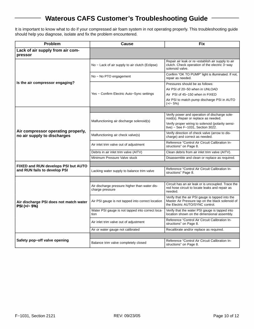
Waterous CAFS Customer’s Troubleshooting Guide
It is important to know what to do if your compressed air foam system in not operating properly. This troubleshooting guideshould help you diagnose, isolate and fix the problem encountered.
Problem Cause Fix
Lack of air supply from air com-pressor
No − Lack of air supply to air clutch (Eclipse)Repair air leak or re−establish air supply to airclutch. Check operation of the electric 3−waysolenoid valve.
No − No PTO engagementConfirm “OK TO PUMP” light is illuminated. If not,repair as needed.
Is the air compressor engaging?
Yes − Confirm Electric Auto−Sync settings
Pressures should be as follows:
Air PSI of 20−50 when in UNLOAD
Air PSI of 45−150 when in FIXED
Air PSI to match pump discharge PSI in AUTO(+/− 5%)
Malfunctioning air discharge solenoid(s)
Verify power and operation of discharge sole-noid(s). Repair or replace as needed.
Verify proper wiring to solenoid (polarity sensi-tive) − See F−1031, Section 3022.
Air compressor operating properly,no air supply to discharges Malfunctioning air check valve(s)
Verify direction of check valve (arrow to dis-charge) and correct as needed.
Air inlet trim valve out of adjustmentReference “Control Air Circuit Calibration In-structions” on Page 8.
Debris in air inlet trim valve (AITV) Clean debris from air inlet trim valve (AITV).
Minimum Pressure Valve stuck Disassemble and clean or replace as required.
FIXED and RUN develops PSI but AUTOand RUN fails to develop PSI Lacking water supply to balance trim valve
Reference “Control Air Circuit Calibration In-structions” Page 8.
Air discharge pressure higher than water dis-charge pressure
Circuit has an air leak or is uncoupled. Trace thered hose circuit to locate leaks and repair asneeded.
Air discharge PSI does not match waterPSI (+/− 5%)
Air PSI gauge is not tapped into correct locationVerify that the air PSI gauge is tapped into theMaster Air Pressure tap on the black solenoid ofthe Electric AUTO/SYNC control.PSI (+/− 5%)
Water PSI gauge is not tapped into correct loca-tion
Verify that the water PSI gauge is tapped intolocation shown on the dimensional assembly.
Air inlet trim valve out of adjustmentReference “Control Air Circuit Calibration In-structions” on Page 8.
Air or water gauge not calibrated Recalibrate and/or replace as required.
Safety pop−off valve openingBalance trim valve completely closed
Reference “Control Air Circuit Calibration In-structions” on Page 8.

F−1031, Section 2121 Page 11 of 12REV: 09/23/05
Problem Cause Fix
Oil level in the air compressor is lowCheck for oil leaks and repair as needed. UseISO 68 viscosity hydraulic oil, filling to the middleof the sight glass.
Plugged water strainer at oil cooler Remove strainer and clean screen.
System overheatingInadequate water supply
Verify that water is being circulated within thepump (TANK TO PUMP valve completely openwith the TANK FILL valve 1/4 open).
Overheated water supplySupply the pump with fresh cool water and opena discharge valve or TANK FILL valve, allowingthe heated water to be dumped to atmosphere.
Compressor overspeeding in UNLOAD mode
Do not run compressor in excess of 8950 RPM.Compressor speed can be calculated as follows:drive line (engine) speed x 2.5 x gear ratio in thepump transmission.
Temperature gauge inoperativeWires unconnected
Check wire connections at the gauge, sendingunit and power supply.
Temperature gauge inoperative
Wires improperly connectedCheck wiring for proper sequence (green tolarge terminal; yellow to small terminal) − SeeF−1031, Section 3022.
Reservoirs overfilled with oilCheck oil level while on a level surface. Reducelevel to middle of the sight glass.
Excessive oil consumptionFlowing in excess of 200 CFM
Reduce RPM and flow CAFS and recheck oillevel.
Excessive oil consumption
Oil/Air filter torn or damagedResult of flowing air in excess of 200 CFM. Re-place air filter, flow CAFS, shut down the pumpfor 15 minutes and check oil level.
Oil siphon line and check valveCheck oil siphon line for obstruction and inspectcheck valve for operation.
Excessive compressor bleed down time Inlet air trim valve closed too farReference “Control Air Circuit Calibration In-structions” on Page 8.
(time may vary)Debris in inlet air trim valve
Clean valve and reference “Control Air Circuit Cal-ibration Instructions” on Page 8.
Electric Auto−Sync in FIXED or AUTOPlace the Electric Auto−Sync in the UNLOADsetting.
Engine stalls upon compressor engage-ment Engaging compressor when under load
Operating under this condition causes the com-pressor oil to accumulate in the compressorcreating a condition similar to a hydraulic pump.To correct, allow air to bleed off, restart the com-pressor and immediately begin flowing airthrough a discharge.
Air compressor locked upDue to a lack of compressor oil/lubrication. Re-pair or replace the compressor.
Air flow digital display stuck at “ 0” CFM Digital display cable defective/or disconnectedCheck cable connections at the meter and digitaldisplay.
or inoperativeAir flow meter not powered
Check for damaged connectors in the meter orcable. Check pin connections for tightness andproper fit.

F−1031, Section 2121 Page 12 of 12REV: 09/23/05
Problem Cause Fix
Using wetting agent in place of foam Flush system and install Class “A” foam.
Poor foam solution (wet or dry) Lack of foam
Check if the Foam Pro system in on. Check if thereis foam in the reservoir. Make sure the foam supplyvalve is on and the Y strainer clean. Reference theFoam Pro instruction manual.
Incorrect size air lines to dischargesRefer to “Air Distribution Hose Size Guidelines”in F−1031, Section 3022.
Foam dumped into the water tank Flush water tank and pump until foam is cleared.
Foam cell is leaking into water tank
Condition applies to tanks utilizing a commonwall(s) between the foam tank and the watertank. If a leak is confirmed, repair the foam tankand flush the water tank and pump until foam iscleared.
Foam in water system
Foam proportioning manifold check valve mal-function
If the above conditions have been corrected, thefinal cause for foam in the water tank may be theresult of a malfunctioning foam manifold checkvalve. To troubleshoot, cap off one foam dis-charge that is plumbed to the foam manifold,open that discharge valve and increase thepump discharge to 30−40 PSI. Disengage thepump and monitor the corresponding dischargePSI gauge, looking for a drop in discharge pres-sure. If the PSI drops, it indicates the foam man-ifold check valve is leaking and requires repair.
Water in compressors oil/airLeaking oil cooler
Isolate the heat exchanger and check for leaks.Replace if necessary. (Typical cause is freez-ing.)
Discharge air check valve(s) malfunctioningConfirm direction (arrow towards dischargevalve). Replace if necessary.
Engaging compressor with the Electric Auto−Sync in the Fixed or Auto Mode
Disengage compressor and place Electric Auto−Sync setting to UNLOAD, allow compressor tobleed off, then engage the compressor.
High RPM engagementReduce engine RPM and engage in the UN-LOAD position with the Master Air Pressuregauge reading “0”.
Clutch smoking Not allowing for compressor to bleed down priorto re−engaging
Allow ample time for compressor to bleed down.Re−engage the compressor in the UNLOADposition.
Contaminated clutch disc or plateInspect the clutch disc and plate for contami-nants (oil, dirt, foam, etc.). Clean or replace asnecessary.
Low air pressure or supply leak to clutchCheck pressure at supply side. Check supplyline for leaks.
Compressor locked up Check entire system and repair as needed.
Safety pop−off valve opening at lowpressure Sump fire damaged pop−off valve
Check the system and oil level. Replace thepop−off valve. Once repaired, operate the com-pressor watching for air or oil being dischargedfrom the pop−off valve. One indication of a pop−off valve failure is oil present throughout thepump compartment. Check for signs of sumpfire.
Compressor locked upDebris in the compressor Check entire system and repair as needed.