Embed Size (px)
Citation preview

The City of Winnipeg Appendix „G‟Bid Opportunity No. 473-2016
Template Version: C120150806- C BCivil
APPENDIX „G‟
CRASH ATTENUATION BARRELS PRODUCT INFORMATION

Energite® IIIFitch® UniversalModule systems
Assembly and Maintenance Manual
Revision E August 2012Part No. 619488B

www.enewww.hig
This Maat all timor down
The instrinformatiIII/Fitch® time of pAbsorptio
ergyabsorptihwayguardra
FM
Ass
ImpoassemSysteappromainteparambeen nationAbsor
nual must mes. For ad
load from w
ructions conon, illustratiUniversal M
printing. Weon Systems
on.com ail.com
EFitcModsembly
ortant: Thembly, maintems. These
opriate highwenance, or
meters, contaaccepted fo
nal highway rption System
be availableditional cop
websites be
ntained in thons, and sp
Module Systee reserve thto confirm th
Enerch® Uduley and M
2525 SteDallas
ese instructenance, and
instructionway authority
repair wouact the approor use by th
system unms represen
e to the wopies, contacelow.
is Manual specificationsems informae right to mhat you are r
1
rgiteUniv
e Sy
Mainte
emmons Frees, Texas 7520
tions are tod repair of thns are for y only. In thuld require opriate highwhe Federal nder strict cntatives are a
orker oversct Energy A
supersede as in this Maation availabmake changreferring to t
A
e® IIIvers
ystemnance
eway 07
o be used ohe Energite®
standard ahe event the
a deviatioway authoritHighway Ad
criteria utilizavailable for
eeing and/oAbsorption
ll previous inual are ba
ble to Energes at any tthe most cur
PRevisio
All rights in co
I sal ms Manu
only in conj® III/Fitch® Uassembly s specified sn from staty engineer. dministration
zed by that r consultatio
or assemblSystems at
nformation aased on they Absorptionime. Pleaserrent instruct
Part No. 619on E Augustopyright rese
al
junction withUniversal Mospecified byystem asse
andard asseThis system
n for use onagency. En
n if required
ling the prot (888) 323-
and Manuale latest Enern Systems ae contact Entions.
488B 2012 erved
h the odule y the mbly, embly m has n the nergy
d.
oduct -6374
ls. All rgite® at the nergy
www.energyabsorption.com Revision E August 2012 www.highwayguardrail.com 2 All rights in copyright reserved
Table of Contents Customer Service Contacts .......................................................................................................... 3 Important Introductory Notes ........................................................................................................ 3 Recommended Safety Rules for Assembly .................................................................................. 4 Safety Symbols ............................................................................................................................. 5 Warnings and Cautions ................................................................................................................. 5 Limitations and Warnings .............................................................................................................. 6 Important Introductory Notes ........................................................................................................ 7 System Overview .......................................................................................................................... 8 Recommended Tools .................................................................................................................... 9 Site Preparation/Foundation ....................................................................................................... 10 Inspect Shipment ........................................................................................................................ 10 Assembly .................................................................................................................................... 11 Alternate Assembly Option ......................................................................................................... 15 Checking the Assembled System ............................................................................................... 16 Maintenance Checklist ................................................................................................................ 16
Visual Drive-By Inspection Checklist ..................................................................................... 16 Walk-Up Inspections Checklist .............................................................................................. 17
Refurbishment Procedures ......................................................................................................... 18 Alternate Refurbishment Option ............................................................................................ 19 Maintenance Log................................................................................................................... 20

www.energyabsorption.com Revision E August 2012 www.highwayguardrail.com 3 All rights in copyright reserved
Customer Service Contacts Energy Absorption Systems (a Trinity Highway Products company) is committed to the highest level of customer service. Feedback regarding the Energite® III/Fitch® Universal Module Systems, its assembly procedures, supporting documentation, and performance is always welcome. Additional information can be obtained from the contact information below: Energy Absorption Systems:
Telephone: (888) 323-6374 (USA Only) (214) 589-8140 (USA or International)
E-mail: [email protected]
Internet: Energy Absorption Systems Trinity Highway Products, LLC Trinity Industries, Inc.
http://www.energyabsorption.com http://www.highwayguardrail.com http://www.trin.net
Important Introductory Notes Proper assembly of the Energite® III/Fitch® Universal Module Systems is essential to achieve performance of the system under appropriate federal and state criteria. These instructions should be read in their entirety and understood before assembling the Energite® III/Fitch® Universal Module Systems. These instructions are to be used only in conjunction with the assembly of the Energite® III/Fitch® Universal Module Systems and are for standard assemblies only as specified by the applicable highway authority. In the event your system assembly requires or involves deviation from standard parameters or, during the assembly process a question arises, please contact the appropriate highway authority that specified this system at this particular location for guidance. Energy Absorption Systems is available for consultation with that agency. These instructions are intended for an individual who is qualified to both read and accurately interpret them as written. They are intended for the individual who is experienced and skilled in the assembly of highway products which are specified and selected by the highway authority.
A set of product and project shop drawings will be supplied by Energy Absorption Systems. The shop drawings will be for each section of the assembly. These drawings should be reviewed and studied thoroughly by a qualified individual who is skilled in interpreting them before the start of any assembly.
www.enewww.hig
Recom* ImportaThis Manand expeModule Systems This Macontact EManual o
Always uand whecompone
Safety mused to p
ergyabsorptihwayguardra
Impodirectrepairwarninfurthethese
WarnWarniUnivewarnin
mmendeant Safety Inual must beerienced in Systems. Aby calling
nual may aEnergy Absoor about the
use approprien moving ents. Gloves
measures incprovide safet
on.com ail.com
ortant: Reaions and sring the Eneng can resu
er compromisinstructions
ning: Ensurings, Cautiorsal Moduleng could res
ed Safetnstructionse kept in a the assemb
Additional co(888) 323-6
also be doworption SysteEnergite® II
ate safety pheavy equip
s, safety gog
corporating trty for person
4
ad safety iuggested srgite® III/Fitcult in seriouses the acc
s for later use
re that all ofons, and Ime Systems Msult in seriou
ty Ruless * location whe
bly, maintenaopies of th6374 or by wnloaded diems if you hI/Fitch® Univ
recautions wpment or thgles, steel to
raffic contronnel while at
4
nstructions safe practicech® Universas injury or eptance of te.
f the Energitmportant staManual are c
s injury or d
s for Ass
ere it is readance, or repis Manual email at cu
irectly from ave any queversal Modu
when operathe Energiteoe boots, an
l devices spt the assemb
A
thoroughly es before aal Module Sydeath to wothis system
te® III/Fitch®
atements wicompletely foeath.
sembly
dily availablepair of the Eare availabustomerservthe websit
estions concle Systems.
ting power ee® III/Fitch®
nd back prot
ecified by thbly, mainten
RevisioAll rights in co
and followassembling, ystems. Faiorkers and/by the FHW
® Universal thin the En
ollowed. Fai
e to personsEnergite® IIIble from Envice@energytes indicatedcerning the in
equipment, mUniversal M
ection shall
he highway aance, or rep
on E Augustopyright rese
w the assemaintainin
lure to followor bystande
WA. Please
Module Sysnergite® III/Flure to follow
s who are s/Fitch® Univ
nergy Absoryabsorption.d below. Pnformation i
mixing chemModule Sysbe used.
authority mupair site.
2012 erved
embly g, or w this ers. It keep
stems Fitch® w this
skilled versal rption .com. lease n this
micals, stems
ust be
www.enewww.hig
SafetyThis secModule maintena
Symbo
WarniRead alUniversa
ergyabsorptihwayguardra
y Symboction describ
Systems Mance, repair,
ol Mean
Safetand foseriou
ings andl instruction
al Module Sy
Warnread Warnifollowunderseriou
Warnspecifthe asresult
Warnfor thmaintanot utare ohave mainteprohibthe ev
Warnwarnin
Warnstate, could
WarnTrafficwarnin
on.com ail.com
ols bes the safeManual. Re and service
ing
ty Alert Syollow the Dus injury or d
d Cautions before aystems.
ning: Do nothis Manuaings, Cautio
wed. Please crstand theseus injury or d
ning: Safetyfied by the hssembly, main serious in
ning: Use ohe Energiteaining, or retilize or othether Energynot been
enance, or bited. Failurevent of a veh
ning: Do NOng could res
ning: Ensurspecifying result in ser
ning: Ensurc Control Dng could res
5
ety symbolsad the Ma
e information
ymbol: IndicDanger, Wardeath to the w
ons assembling,
t assemble, al thoroughlns, and Impcall Energy Ae instructiondeath.
y measureshighway authaintenance,njury or deat
only Energy e® III/Fitchepairing the erwise cominy Absorptiontested, norrepairs us
e to follow thhicle impact
OT modify tsult in seriou
e that the baagency, andrious injury o
e that your Devices (MUsult in seriou
5
s that appeaanual for cn.
cates Dangerning, Safetyworkers and
maintaining
maintain, ory and com
portant StateAbsorption Sns. Failure
s incorporathority must bor repair s
th.
Absorption ® UniversaEnergite® I
ngle parts fron Systems or have theysing unspechis warning with an UNA
he barrier ss injury or d
arrier systemd local specor death in th
assembly mUTCD) and s injury or d
A
ar in this Ecomplete sa
er, Warningy, or Cautiod/or bystand
g, or repair
r repair the bmpletely undements withiSystems at to follow th
ting appropbe used to pite. Failure
Systems paal Module II/Fitch® Unom other sysor Trinity syy been acccified partscould result
ACCEPTED
system in aneath in the e
m and delinecifications. Fhe event of a
meets all applocal standeath in the e
RevisioAll rights in co
Energite® III/afety, asse
, or Cautionon indicatorsers.
ring the En
barrier systederstand it. n the Manua(888) 323-6his warning
priate traffic protect all peto follow th
arts that areSystems
iversal Modstems even ystems. Succepted for
s or accesst in serious system.
ny way. Failevent of a co
eation used Failure to foa collision.
propriate Madards. Failuevent of a co
on E Augustopyright rese
/Fitch® Univmbly, opera
n. Failure to s could res
nergite® III/F
em until you Ensure tha
al are comp374 if you d
g could resu
control deersonnel whis warning c
e specified hfor assemule Systemsif those sys
ch configurause. Asse
sories is sinjury or dea
ure to followollision.
meet all fedllow this wa
anual on Unre to followollision.
2012 erved
versal ating,
read ult in
Fitch®
have at all letely
do not ult in
evices hile at could
herein bling, s. Do stems ations mbly, trictly ath in
w this
deral, arning
niform w this
www.energyabsorption.com Revision E August 2012 www.highwayguardrail.com 6 All rights in copyright reserved
Limitations and Warnings The Energite® III/Fitch® Universal Module systems have been tested and evaluated per recommendations of the National Cooperative Highway Research Program (NCHRP) Report 350* for Test Level 3, gating, and non-redirective impact conditions. The Energite® III/Fitch® Universal Module systems, as currently designed with the proper array, have been shown in federally approved crash testing to be capable of decelerating and stopping light and heavy weight vehicles (820 to 2000 kg, 1810 to 4410 lbs.) when impacted head-on or at angles from 0 degrees to 15 degrees and at 100 km/h (62 mph). Tests were conducted on slopes less than 5% and without curbs.
The Energite® III/Fitch® Universal Module Systems are non-redirective crash cushions and should be used appropriately.
Curbs may create a vehicle ramping condition which could cause an untested effect on the impacting vehicle. Therefore, do not assemble this product on or near curbs.
Energy Absorption Systems, in compliance with the National Cooperative Research Highway Program 350 (NCHRP Report 350) “Recommended Procedures for the Safety Performance of Highway Safety Features”, contracts with FHWA approved testing facilities to perform crash tests, evaluation of tests, and submittal of results to the Federal Highway Administration for review.
The Energite® III/Fitch® Universal Module Systems was tested to meet the impact criteria, requirements, and guidelines of NCHRP Report 350. These tests, specifically set forth by FHWA, evaluate product performance by simulating those impacts outlined by NCHRP Report 350 involving a typical range of vehicles on our roadways, from lightweight cars (approx. 820kg [1800 lb.]) to full size pickup trucks (approx. 2000 kg [4400 lb.]) as specified by the FHWA. A product can be certified for multiple Test Levels. The Energite® III/Fitch® Universal Module Systems is certified to the Test Level(s) as shown below:
Test Level 3: 100 km/h [62 mph]
These FHWA directed tests are not intended to represent the performance of systems when impacted by every vehicle type or every impact condition existing on the roadway. This system is tested only to the test matrix criteria of NCHRP 350 as approved by FHWA. Energy Absorption Systems does not represent nor warrant that the results of these controlled tests show that vehicle impacts with the products in other conditions would necessarily avoid injury to person(s) or property. Impacts that exceed the specifications of the system may not result in acceptable crash performance as outlined in NCHRP Report 350, relative to structural adequacy, occupant risk, and vehicle trajectory. Energy Absorption Systems expressly disclaims any warrant or liability for injury or damage to persons or property resulting from any impact, collision, or harmful contact with products, other vehicles, or nearby hazards or objects by any vehicle, object or person, whether or not the products were assembled by or under the direction of Energy Absorption Systems or by third parties.

www.energyabsorption.com Revision E August 2012 www.highwayguardrail.com 7 All rights in copyright reserved
Important Introductory Notes Proper deployment and maintenance of the Energite® III/Fitch® Universal Module Systems is critical to achieve performance under appropriate state and federal guidelines. Take the time to thoroughly review this Manual, including the Limitations and Warnings section, before performing the necessary work. Do not attempt to assemble any Energite® III/Fitch® Universal Module Systems without the proper plans and assembly Manual from the manufacturer. If you require additional information, or have questions about the Energite® III/Fitch® Universal Module Systems, please contact Energy Absorption Systems Customer Service Department. See Customer Service Contacts on Page 3 of this Manual.

www.energyabsorption.com Revision E August 2012 www.highwayguardrail.com 8 All rights in copyright reserved
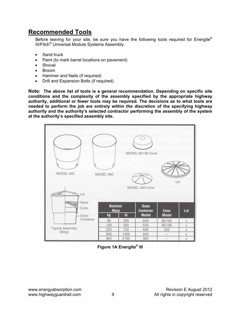
System Overview The Energite® III/Fitch® Universal Module systems are gating, non-redirective, and easy-to-assemble crash cushions consisting of a number of sand-filled modules that are assembled in a specific geometric array in front of a hazard.
Each module of the Energite® III consists of a one-piece barrel, a lid, and in some cases a cone insert. The cone insert is used to adjust the sand height or center-of-mass and the overall weight of the barrel. The barrel’s weight requirement is determined by its place within the array.
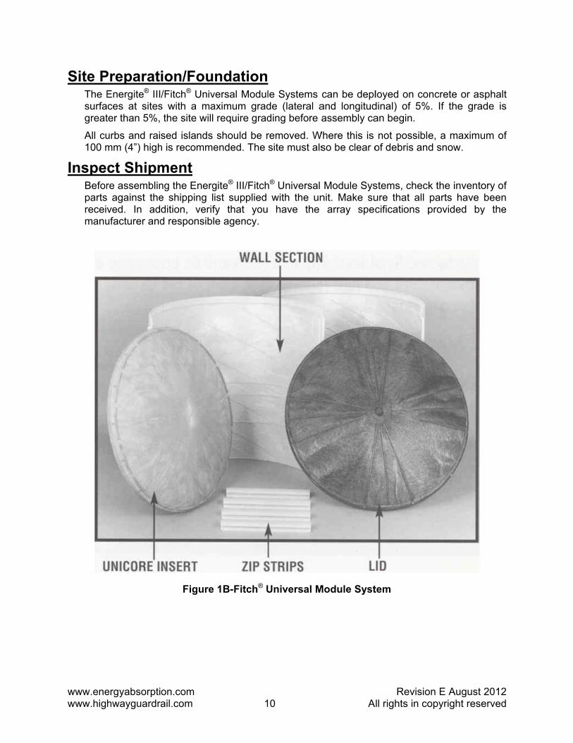
Each module of the Fitch® Universal Module consists of one set of walls, one core, one lid and four zip strips. These components will make any weight module 90k 180, 320, 640, 960 kg (200, 400, 700, 1400 and 2,100 lb.) required.
The Energite® III/Fitch® Universal Module Systems modules are available in 90, 180, 320, 640 and 960 kg (200, 400, 700, 1400 and 2,100 lb.) sizes. Refer to Figures 1A/B and 2A/B.
www.enewww.hig
RecomBeforIII/Fit
• S• P• S• B• H• D
Note: Tconditioauthorityneeded authorityat the au
ergyabsorptihwayguardra
mmendere leaving fotch® Univers
Sand truck Paint (to marShovel Broom Hammer andDrill and Expa
The above lons and they, additionato performy and the authority’s sp
on.com ail.com
ed Toolsor your siteal Module S
k barrel loca
Nails (if reqansion Bolts
list of toolse complexital or fewer the job ar
authority’s specified ass
9
s , be sure y
Systems Ass
ations on pav
quired) s (if required
s is a generty of the atools may
re entirely wselected cosembly site
Figure 1
9
you have theembly.
vement)
)
ral recommassembly sbe requiredwithin the d
ontractor pe.
1A Energite
A
e following
mendation. Dpecified byd. The decidiscretion
erforming th
e® III
RevisioAll rights in co
tools requir
Depending y the approsions as toof the speche assembl
on E Augustopyright rese
red for Ener
on specificopriate higho what toolscifying highly of the sy
2012 erved
rgite®
c site hway s are hway
ystem
www.enewww.hig
Site PThe Esurfagreat
All cu100 m
InspeBeforpartsreceivmanu
ergyabsorptihwayguardra
PreparatEnergite® IIIces at sitester than 5%,
urbs and raimm (4”) high
ct Shipmre assemblin against theved. In adufacturer and
on.com ail.com
ion/Fou/Fitch® Univ
s with a mathe site will
sed islands h is recomme
ment ng the Energe shipping ldition, verifd responsibl
Figure
1
ndationversal Modulaximum grad
require grad
should be rended. The
gite® III/Fitchist supplied fy that youe agency.
1B-Fitch® U
0
le Systems de (lateral ading before a
removed. Wsite must als
h® Universal with the un
have the
Universal M
A
can be depland longitudassembly ca
Where this is so be clear o
Module Sysnit. Make su
array spec
Module Syst
RevisioAll rights in co
loyed on codinal) of 5%an begin.
not possibleof debris and
stems, checkure that all cifications p
tem
on E Augustopyright rese
ncrete or as%. If the gra
e, a maximud snow.
k the inventoparts have provided by
2012 erved
sphalt de is
um of
ory of been
y the

www.enewww.hig
Assem
Tst
1) PP
2) RC
3) TTaah
4) PPa
ergyabsorptihwayguardra
mbly
Cautidesignapprolevels
The Energiteteps to follow
Place traffic Place traffic c
Review arrayCarefully revi
Take measuTake measur
ccording to t least 762 azard (See
Position the Position the b
t the top of t
on.com ail.com
ion: The Ened and sp
opriate highws for errant ve
® III/Fitch® Uw.
control devcontrol devic
y specificatew the array
rements rements to pthe specificamm (30”) aFigure 2).
barrels barrels with the barrel) a
1
Energite® III/pecified by way authorityehicles and
Universal Mo
vices ces to protec
tions y specificatio
properly posations. Thesand be posit
F
approximateccording to t
1
/Fitch® Univa qualified
y. Improper possible inju
odule System
ct your crew
on provided
sition the firsse barrels mutioned a mi
Figure 2
ely 152 mm the array sp
A
versal Modud engineerplacement curies to occu
ms should b
and motoris
by a qualifie
st row of baust be lateranimum of 3
(6”) of spacecifications
RevisioAll rights in co
le Systems assigned t
could result upants.
be assemble
sts.
ed engineer.
arrels (closeally offset fro305 mm (12
ce between (See Figure
on E Augustopyright rese
array shouhis task byin excessiv
ed in order o
.
st to the haom the haza2”) in front o
them (mease 3).
2012 erved
ld be y the
ve “G”
of the
azard) ard by of the
sured
www.enewww.hig
5) TAp
6) MMpto
7) MAthe
Wvi
•
•
ergyabsorptihwayguardra
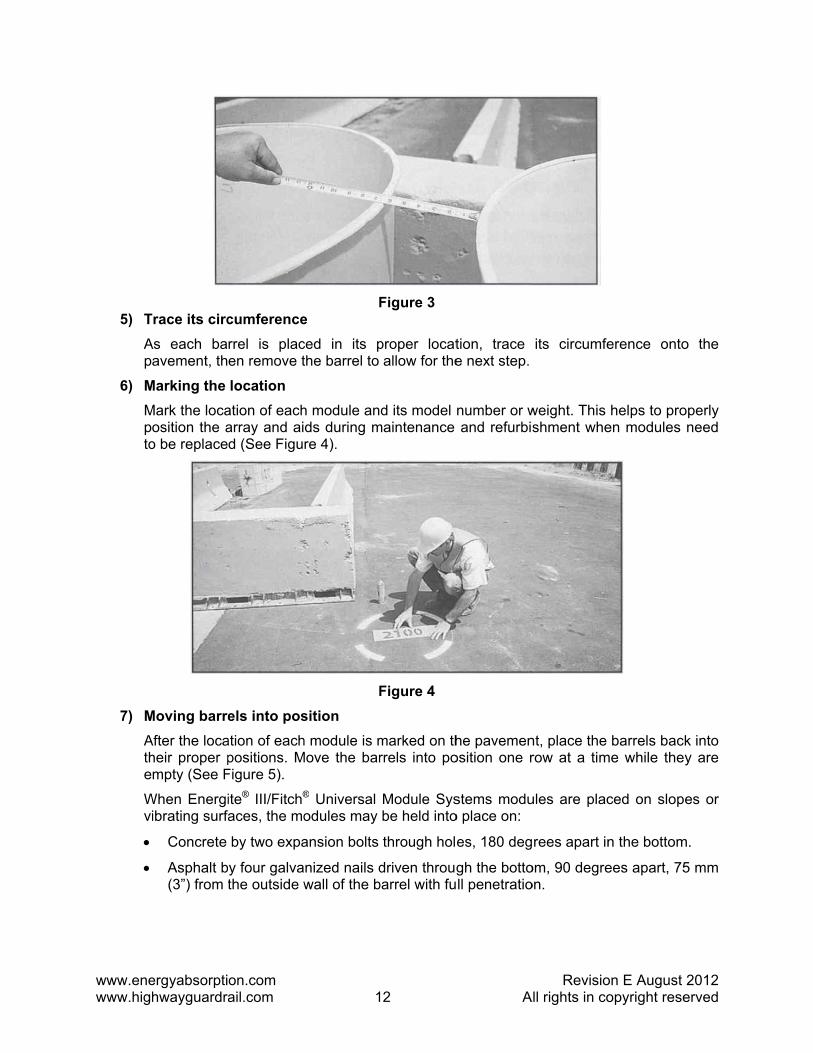
Trace its circAs each ba
avement, th
Marking the Mark the loca
osition the ao be replace
Moving barreAfter the locaheir proper pmpty (See F
When Energiibrating surfa
Concrete
Asphalt b(3”) from t
on.com ail.com
cumferencerrel is placen remove t
location ation of eacharray and aid (See Figu
els into posation of eachpositions. MFigure 5).
ite® III/Fitch®
aces, the mo
by two expa
y four galvathe outside w
1
Fe ced in its pthe barrel to
h module ands during mre 4).
Fsition h module is mMove the bar
® Universal odules may
ansion bolts
nized nails dwall of the b
2
Figure 3
proper locatallow for the
d its model maintenance
Figure 4
marked on thrrels into po
Module Sysbe held into
through hol
driven througbarrel with fu
A
tion, trace e next step.
number or wand refurbis
he pavemenosition one r
stems moduo place on:
es, 180 deg
gh the bottoll penetratio
RevisioAll rights in co
its circumfe
weight. This shment whe
nt, place the row at a tim
ules are plac
rees apart in
om, 90 degreon.
on E Augustopyright rese
erence onto
helps to proen modules
barrels bacme while the
ced on slop
n the bottom
ees apart, 75
2012 erved
o the
operly need
k into y are
es or
m.
5 mm
www.enewww.hig
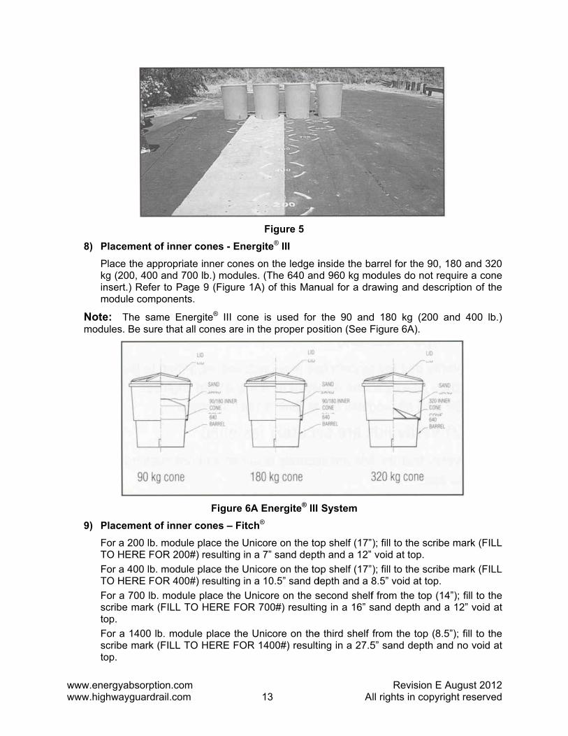
8) PPkginm
Notemodu
9) PFTFTFsctoFscto
ergyabsorptihwayguardra
Placement oPlace the appg (200, 400
nsert.) Refermodule comp
e: The samules. Be sure
Placement oor a 200 lb.
TO HERE FOor a 400 lb.
TO HERE FOor a 700 lb. cribe mark (op. or a 1400 lbcribe mark (op.
on.com ail.com
of inner conpropriate innand 700 lb.
r to Page 9 ponents.
me Energitee that all con
Fof inner con
module placOR 200#) res
module placOR 400#) res
module pla(FILL TO HE
b. module pl(FILL TO HE
1
Fes - Energit
ner cones on) modules. ((Figure 1A)
e® III cone ines are in th
Figure 6A Ees – Fitch®
ce the Unicosulting in a 7ce the Unicosulting in a 1ce the Unico
ERE FOR 70
lace the UniERE FOR 14
3
Figure 5 te® III n the ledge i(The 640 anof this Man
is used for e proper pos
Energite® III
ore on the to7” sand deptore on the to10.5” sand dore on the s00#) resultin
icore on the400#) resulti
A
inside the bad 960 kg mo
nual for a dra
the 90 andsition (See F
System
op shelf (17”th and a 12” op shelf (17”depth and a 8second shelfng in a 16” s
e third shelf ing in a 27.5
RevisioAll rights in co
arrel for the odules do noawing and d
d 180 kg (2Figure 6A).
); fill to the svoid at top. ); fill to the s8.5” void at tf from the tosand depth a
from the top5” sand dept
on E Augustopyright rese
90, 180 andot require a description o
200 and 400
scribe mark
scribe mark top.
op (14”); fill tand a 12” vo
p (8.5”); fill tth and no vo
2012 erved
d 320 cone
of the
0 lb.)
(FILL
(FILL
to the oid at
to the oid at
www.enewww.hig
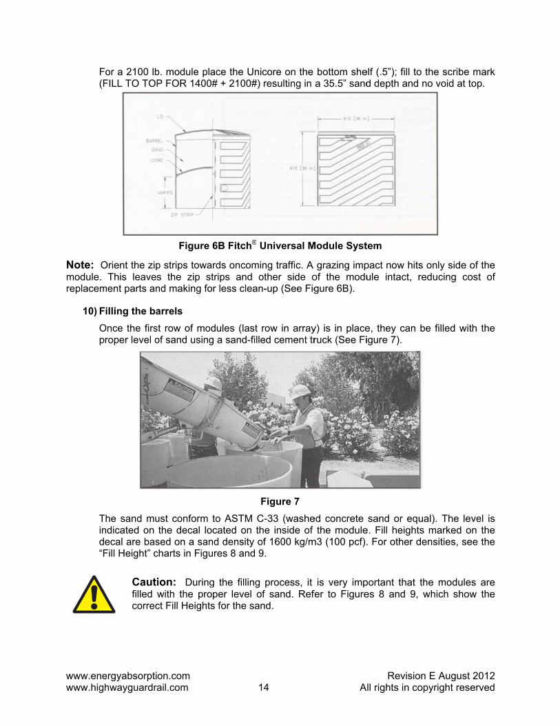
F(F
Note: Omodule. replacem
10) FOp
Tind“F
ergyabsorptihwayguardra
or a 2100 lbFILL TO TOP
Orient the zipThis leaves
ment parts an
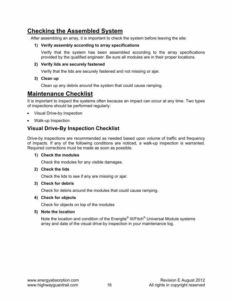
illing the baOnce the firs
roper level o
The sand mundicated on ecal are basFill Height” c
Cautifilled correc
on.com ail.com
b. module plP FOR 1400
p strips towas the zip snd making fo
arrels st row of moof sand using
ust conform the decal lo
sed on a sancharts in Figu
ion: Duringwith the proct Fill Height
Figure
1
ace the Uni0# + 2100#)
ards oncomistrips and oor less clean
odules (last g a sand-fille
Fto ASTM C
ocated on thnd density oures 8 and 9
g the filling oper level ots for the san
6B Fitch® U
4
core on the resulting in
ng traffic. A other side on-up (See Fig
row in arrayed cement tr
Figure 7 C-33 (washehe inside of of 1600 kg/m9.
process, it f sand. Refnd.
Universal M
A
bottom shea 35.5” sand
grazing impof the modugure 6B).
y) is in placeruck (See Fi
ed concrete the module
m3 (100 pcf).
is very impfer to Figure
Module Syst
RevisioAll rights in co
elf (.5”); fill tod depth and
pact now hitsule intact, r
e, they can igure 7).
sand or eque. Fill height. For other d
portant that es 8 and 9,
tem
on E Augustopyright rese
o the scribe no void at to
s only side oreducing co
be filled wit
ual). The levts marked odensities, se
the moduleswhich show
2012 erved
mark op.
of the ost of
th the
vel is n the
ee the
s are w the

www.enewww.hig
11) LTmcofr
Altern1) T
atou
2) B
ergyabsorptihwayguardra
FITCH® U
ENER
Cautimix thsure t
Lid PlacemeThe lids can modules canompleted. Brom entering
nate AssThe Energite
llows the moo the deploysing a crane
Barrels may b
on.com ail.com
NIVERSAL
200
400
700
1400
2100
Fi
RGITE® MOD
200
400
700
1400
2100
ion: If the he sand withhe salt is ev
ent be snapped
n be positioBe sure the g the barrels,
sembly Oe® Barrels feodules to beyment site. Te and lifting d
be placed on
1
MODULE (l
igure 8-Fitc
DULE (lbs)
Figure 9
modules areh 5% rock svenly dispers
d firmly into oned, filled, lids are sna, which can
Optioneature a cone fully assemThe fully-assdevice.
n 100 mm (4
Prope
Proper Sa
5
lbs) FILL H
h® Universa
FILL HEIG
9 - Energite
e located whalt by weigh
sed in the sa
place. After and the lid
apped firmlyadversely af
nvenient onembled and fillsembled mo
4”) maximum
r Sand Leve
and Levels
A
HEIGHT FR
1
8
6
To
To
al Module
GHT FROM T
8.5
5
4
3
0
e® III
here freezinht to prevenand.
r the first rowds snapped
y into place ffect the sys
e-piece desied at a remo
odules can b
m height palle
els
RevisioAll rights in co
ROM TOP (in
12
8.5
6
op
op
TOP (inche
ng temperatut the sand f
w is finishedd on until ato prevent w
stem’s perfor
gn with a sote site and be lifted on
ets for temp
on E Augustopyright rese
nches)
es)
ures might ofrom freezing
d, the next roall the rowswater and drmance.
olid bottom.then transpand off the
porary assem
2012 erved
occur, g. Be
ow of s are debris
This ported
truck
mbly.
www.energyabsorption.com Revision E August 2012 www.highwayguardrail.com 16 All rights in copyright reserved
Checking the Assembled System After assembling an array, it is important to check the system before leaving the site:
1) Verify assembly according to array specifications Verify that the system has been assembled according to the array specifications provided by the qualified engineer. Be sure all modules are in their proper locations.
2) Verify lids are securely fastened Verify that the lids are securely fastened and not missing or ajar.
3) Clean up Clean up any debris around the system that could cause ramping.
Maintenance Checklist It is important to inspect the systems often because an impact can occur at any time. Two types of inspections should be performed regularly:
• Visual Drive-by Inspection
• Walk-up Inspection
Visual Drive-By Inspection Checklist
Drive-by inspections are recommended as needed based upon volume of traffic and frequency of impacts. If any of the following conditions are noticed, a walk-up inspection is warranted. Required corrections must be made as soon as possible.
1) Check the modules Check the modules for any visible damages.
2) Check the lids Check the lids to see if any are missing or ajar.
3) Check for debris Check for debris around the modules that could cause ramping.
4) Check for objects Check for objects on top of the modules
5) Note the location Note the location and condition of the Energite® III/Fitch® Universal Module systems array and date of the visual drive-by inspection in your maintenance log.
www.enewww.hig
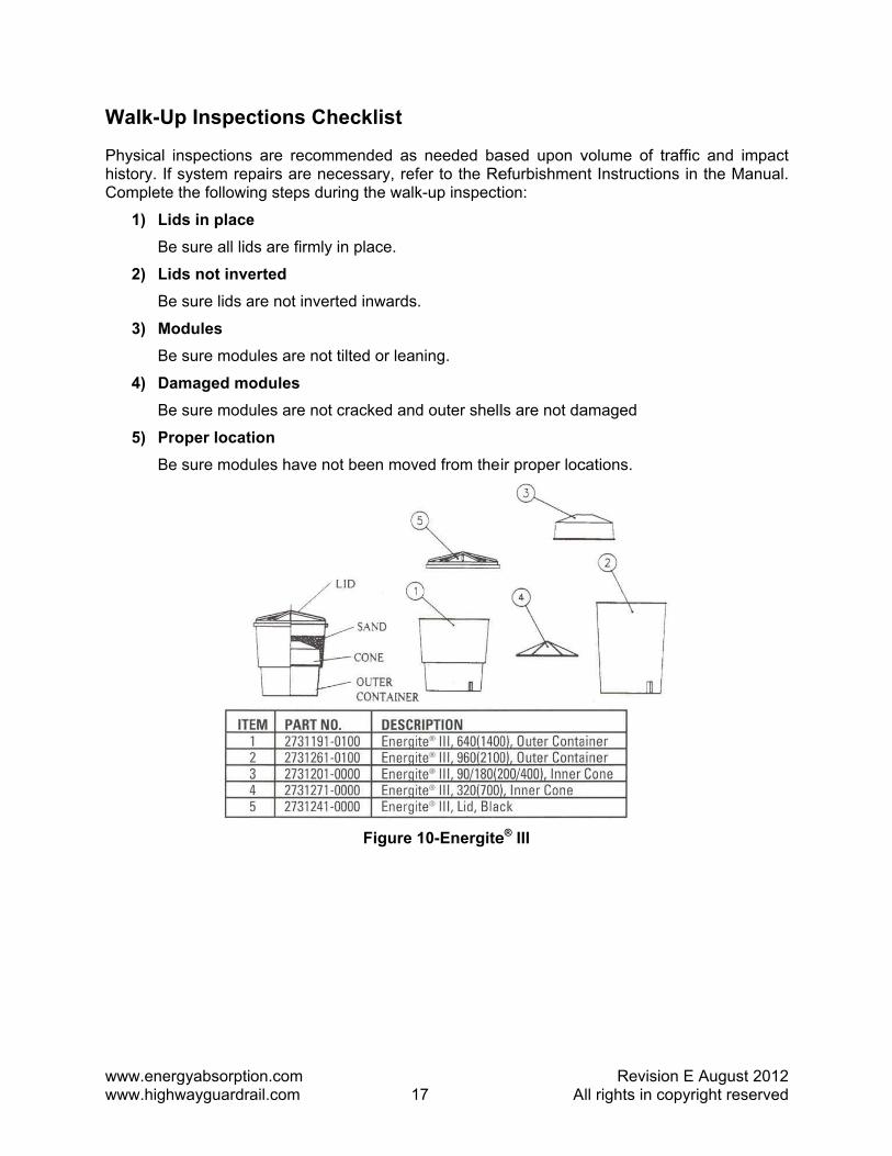
Walk-U
Physical history. IComplete
1) LB
2) LB
3) MB
4) DB
5) PB
ergyabsorptihwayguardra
Up Inspec
inspectionsf system repe the followi
Lids in placeBe sure all lid
Lids not inveBe sure lids a
Modules Be sure modu
Damaged moBe sure modu
Proper locatBe sure modu
on.com ail.com
ctions Ch
s are recompairs are neng steps dur
e ds are firmly
erted are not inver
ules are not
odules ules are not
tion ules have no
1
hecklist
mended as ecessary, refring the walk
in place.
rted inwards
tilted or lean
cracked and
ot been mov
Figure
7
needed bafer to the Rek-up inspect
.
ning.
d outer shell
ved from the
10-Energite
A
ased upon vefurbishmention:
ls are not da
ir proper loc
e® III
RevisioAll rights in co
volume of trnt Instruction
amaged
cations.
on E Augustopyright rese
raffic and imns in the Ma
2012 erved
mpact anual.
www.enewww.hig
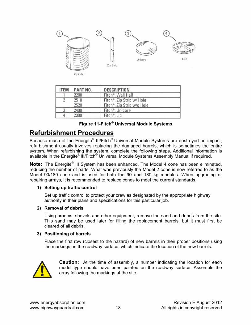
RefurBecauserefurbishsystem. available
Note: Treducing Model 90repairing
1) SSa
2) RUTcl
3) PPth
ergyabsorptihwayguardra
bishmene much of th
ment usuallWhen refurb
e in the Ener
The Energitethe number
0/180 cone arrays, it is
Setting up trSet up traffic
uthority in th
Removal of dUsing broomsThis sand mleared of all
Positioning oPlace the firshe markings
Cautimodearray
on.com ail.com
Figure
nt Procehe Energite®
ly involves rbishing the rgite® III/Fitch
e® III Systemr of parts. Wand is userecommend
raffic controcontrol to pr
heir plans an
debris s, shovels a
may be useddebris.
of barrels st row (close
on the road
ion: At thel type shoufollowing the
1
11-Fitch® U
edures® III/Fitch® Ureplacing thsystem, comh® Universal
m has been What was preed for both ded to replac
ol rotect your cnd specificat
and other eqd later for f
est to the haway surface
e time of asld have beee markings a
8
Universal Mo
niversal Moe damaged
mplete the fo Module Sys
enhanced. Teviously thethe 90 and
ce cones to
crew as desiions for this
quipment, refilling the re
azard) of newe, which indic
ssembly, a nen painted oat the site.
A
odule Syste
odule Systembarrels, wh
following stestems Assem
The Model 4e Model 2 cod 180 kg mmeet the cu
gnated by thparticular jo
move the saeplacement
w barrels incate the loca
number indion the road
RevisioAll rights in co
ems
ms are destrhich is someeps. Additionmbly Manua
4 cone has one is now rodules. Wh
urrent standa
he appropriaob.
and and debbarrels, but
n their propeation of the
icating the ldway surfac
on E Augustopyright rese
royed on imetimes the enal informatial if required.
been eliminreferred to ahen upgradinards.
ate highway
bris from thet it must firs
er positions new barrels
location for e. Assemble
2012 erved
mpact, entire ion is .
nated, as the ng or
e site. st be
using .
each e the

www.enewww.hig
4) OWm
•
•
5) PP1re
Note: Tcones ar
6) FO(Am
Tind
7) SSsa
8) CC
Alterna
The Enallows transpotruck u
The Firequire
ergyabsorptihwayguardra
Other surfacWhen replacmay be held
Concrete by
Asphalt by (3”) from th
Placement oPlace the app
80 and 320 equire a con
The same core in the prop
illing of sanOnce the firstAn efficient
modules is to
The sand mundicated on ecal are bas
Cautimix throck s
Snap the lidsSnap the lidsame proced
Clean up Clean up any
ate Refur
nergite® III bthe replace
orted to the sing a crane
tch® Universe one-half of
on.com ail.com
ces ement modinto place on
y two bolts t
four galvane outside wa
of inner conpropriate innkg (200, 400e insert.)
one is used fper position
nd t row of modmethod of q
o use a sand
ust conform the decal lo
sed on a san
ion: If the he sand withsalt should b
s s firmly into ure until all r
y final debris
rbishmen
barrels featuement modu
damaged se and lifting d
sal Module the modules
1
ules are plan:
hrough hole
ized nails drall of the bar
es ner cones on0 and 700 lb
for the 90 anand the mod
dules is in plquickly filling filled cemen
to ASTM Cocated on thnd density of
modules areh 5% rock sabe evenly dis
place and brows are com
at the site.
nt Option
ure a conveles to be fu
site. The fuldevice.
design allows to be repla
9
aced on slo
es, 180 degre
riven througrrel with full
n the ledge inb.) modules.
nd 180 kg (20dule is filled
lace, they cag the Energint mixer.)
C-33 (washehe inside of f 1600 kg/m3
e located whalt by weighspersed thro
begin workinmpleted.
enient, one–ully assemblly-assemble
ws quick reaced.
A
opes or vibra
ees apart in
gh the bottompenetration.
nside the rep(The 640 an
00 and 400 to the prope
an be filled wte® III/Fitch®
ed concrete the module
3 (100 pcf).
here freezint to prevent ughout the s
ng on the ne
–piece desiged and filled
ed modules
efurbishment
RevisioAll rights in co
ating surfac
the bottom.
m, 90 degre
placement bnd 960 kg m
lb.) moduleser sand leve
with the prop® Universal
sand or eque. Fill height
ng temperatuthe sand fro
sand.
ext row of m
gn with a sod at a remocan be lifte
t on nuisan
on E Augustopyright rese
ces, the mod
ees apart, 75
barrels for thmodules do n
s. Be sure thl (See Page
per level of sModule Sys
ual). The levts marked o
ures might oom freezing
modules usin
olid bottom. ote site and d on and of
ce hits and
2012 erved
dules
5 mm
e 90, not
hat all e 13).
sand. stems
vel is n the
occur, . The
g the
This then
ff the
may

www.energyabsorption.com Revision E August 2012 www.highwayguardrail.com 20 All rights in copyright reserved
Maintenance Log
Type of Inspection Date System Location Drive-By Walk-Up Comments

www.energyabsorption.com Revision E August 2012 www.highwayguardrail.com 22 All rights in copyright reserved
Notes:

www.energyabsorption.com Revision E August 2012 www.highwayguardrail.com 21 All rights in copyright reserved
Notes:

2525 Stemmons FreewayDallas, Texas 75207
888-323-6374 (USA only)214-589-8140 (Outside USA)
www.energyabsorption.comwww.highwayguardrail.com