Embed Size (px)
Citation preview
V
Research and Development Technical Report
.ECOM-4542
LOW PROFILE ANTENNA PERFORMANCE STUDY PART I1:
BROADBAND ANTENNA TECHNIQUES SURVEY
C. M. DeSantisCommu nications/ADP Laboratory
October 1977 : ' i '
Approed for p~ublic release:
distribution unlimited.
ECOM
US ARMY ELECTRONICS COMMAND FORT MONMOUTH, NEW JERSEY 07703
NOTICES
Disclaimers
The findings in this report are not to be construed as anofficial Department of the Army position, unless so desig-nated by other authorized documents.
The citation of trade names and names of manufacturers inthis report is not to be construed as official Governmentindorsement or approval of commercial products or servicesreferenced herein.
Disposition
Destroy this report when it is no longer needed. Do notreturn it to the originator.
UNCLASSIFIEDSECURITY CLASSIFICATION 0F THIS PAGE (When De Entered)
EFORE COPETN FOR
7. AU- Re --- s- 2.GV C. RC PNTC O RNTN ER8
Coomi cAtnnaDPeaborary AREd IF Ma* R7
FortMonmoh,_ndJetey_070 Techniques_____Surveys
9t CEROROLING OGAICEIO NAME AND ADDRESS 0PR;E WNS
Communications/ADP Laboratory 1/ OcErW?USArEl ect-ronics, ConiAanAFort Monmouth, New Jersey 07703 3
$4 MONITORING AGENCY NAME & ADDRESS(if different froo, Contrallint Office) is. SECURITY CLASS. (of this report)
UNCLASSIFIEDI~.DECL ASSIFICATION/ DOWNGRADING
SCHEDULE
16. DISTRIBUTION STATEMENT (of this Report)
Distribution Statement A: Approved for public release; distribution unlimited.
17. DISTRIBUTION STATEMENT (of the abstract entered in Block 20, If different from, Report)
1S. SUPPLEMENTARY NOTES
19. KEY WORDS (Continu~e ort reverse side it nece-eerY and identify by block nuinber)
Small antenna, low-profile antenna, broadband matching, folded antennas, multi-element antennas, antenna loading.
90. ABSTRACT (Conlinu en revere, side If nececemy and Identify by block numbew)
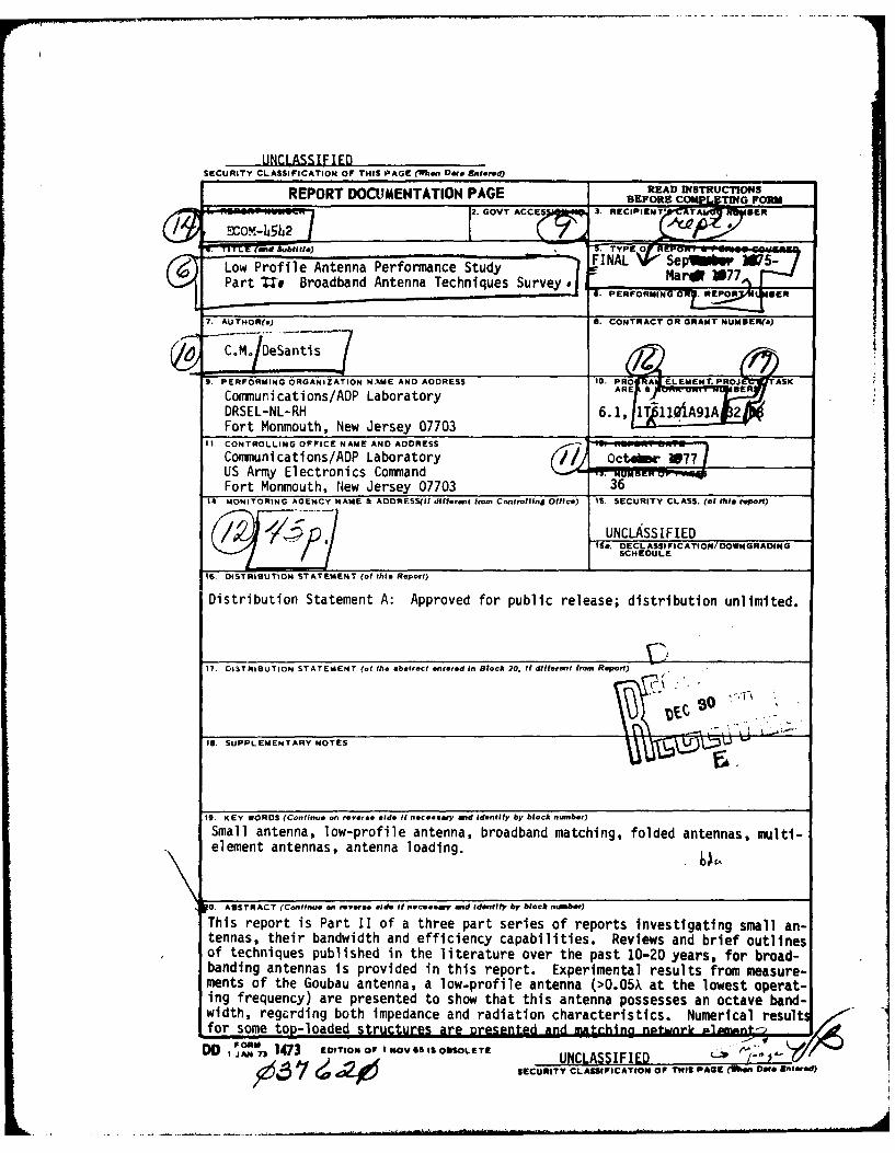
This report is Part 11 of a three part series of reports investigating small an-tennas, their bandwidth and efficiency capabilities. Reviews and brief outlinesof techniques published in the literature over the past 10-20 years, for broad-banding antennas is provided in this report. Experimental results from measure-ments of the Goubau antenna, a low-profile antenna (>0.05X at the lowest operat-ing frequency) are presented to show that this antenna possesses an octave band-width, regcrdlng both impedance and radiation characteristics. Numerical resultfor some top-loaded srcuear eendadmtchino nptwnrk i~mmnt-
DOM 1473 EDI'iOM01N ov as Bis OSSOLETIE UNCLASSIFIED ' ( 4.V'
SECURITY CLASSIFICATION OF THIS3 PAGE (When Date 11111-00
~UNCLASSIFIED
arations aredetermined in order to
estimate the bandwidth.
It is shown
that u2:1 and x4:1 increases in bandwidth are
achieved when top-loading
is
applied to the stub and the
loop antenna, respectively,
and an L-network is
used for tuning and matching. It is concluded that there may be severalsmall but broadband antenna configurations possible from a clever (but asyet unknown) combination of the ideas and techniques presented in thisreport.
UNCLASSIFIEDSECURITY CLASSIPICATION OF THIS PAGE fen Dta Enterod)
CONTENTS
Page1. INTRODUCTION 1
2. DISCUSSION 1
A. Overview 1
B. Passive Loading Using Parasite Elements 1
C. Top-Loaded Antennas 2D. Electrically Thick Antennas 5
E. Folded Antennas 7
F. Conjugate Reactance Loading 12
G. Unusual Designs 13
3. EXPERIMENTAL RESULTS 15
A. Stubs and Loops 15
B. Top-Loaded Loop Antenna 17
C. The Goubau Antenna 19D. Hallen" Antenna 25
4. NUMERICAL MODELING OF TOP-LOADED ANTENNAS 26
A. Top-Loaded Stub and Loop Antennas 26
B. Parasite-Loaded Dipole 32
5. CONCLUSION 32
FIGURES
la. Partial-sleeve or parasite-loaded monopole 3
lb. Sleeve-loaded monopole 3
2a. Four-element, top-loaded antenna 4
2b. Umbrella, top-loaded antenna 4
2c. Spiral, top-loaded antenna 4
3a. Bulb dipole geometry for a broadband antenna 5
3b. Wide-band antenna of unusual shape (In cross-section) 6
3c. Tapered, dielectric lens antenna 6
CONTENTS (CONT'D)
Page
4a. A folded dipole evolved from a simple dipole 7
4b. Adjustable length folded monopole 8
4c. Top-loaded, folded monopole 9
4d. Multiple, folded antenna with mutual coupling 10
4e. Broadband slotted-cone antenna 11
4f. Spiral, top-loaded, folded antenna 11
5a. Hallen' antenna 12
5b. Complementary-pair monopole antenna 13
6a. Monopole-slot antenna 14
6b. Multi-element dipole antenna 14
7 . Impedance variations of several types of small antennas 16
8 . Effect of varying diameter ratio of vertical elements 18in a folded, top-loaded antenna
9 . Goubau antenna - side view 20
10 . Goubau antenna - schematic 20
11 . Radiation pattern - azimuth plane - 500 MHz 21
12 . Radiation pattern - azimuth plane - 900 MHz 22
13 . Relative gain - Goubau antenna vs. X/4 monopole 23
14 Input impedance of Goubau antenna 24
15a. Model of top-loaded monopole for numerical analysis 27
15b. Model of top-loaded, folded, monopole for numerical 27analysis
16 . Required admittance range of shunt inductor in an 28L-network to achieve broadband match
17 . Required impedance range of series inductor to achieve 29broadband match
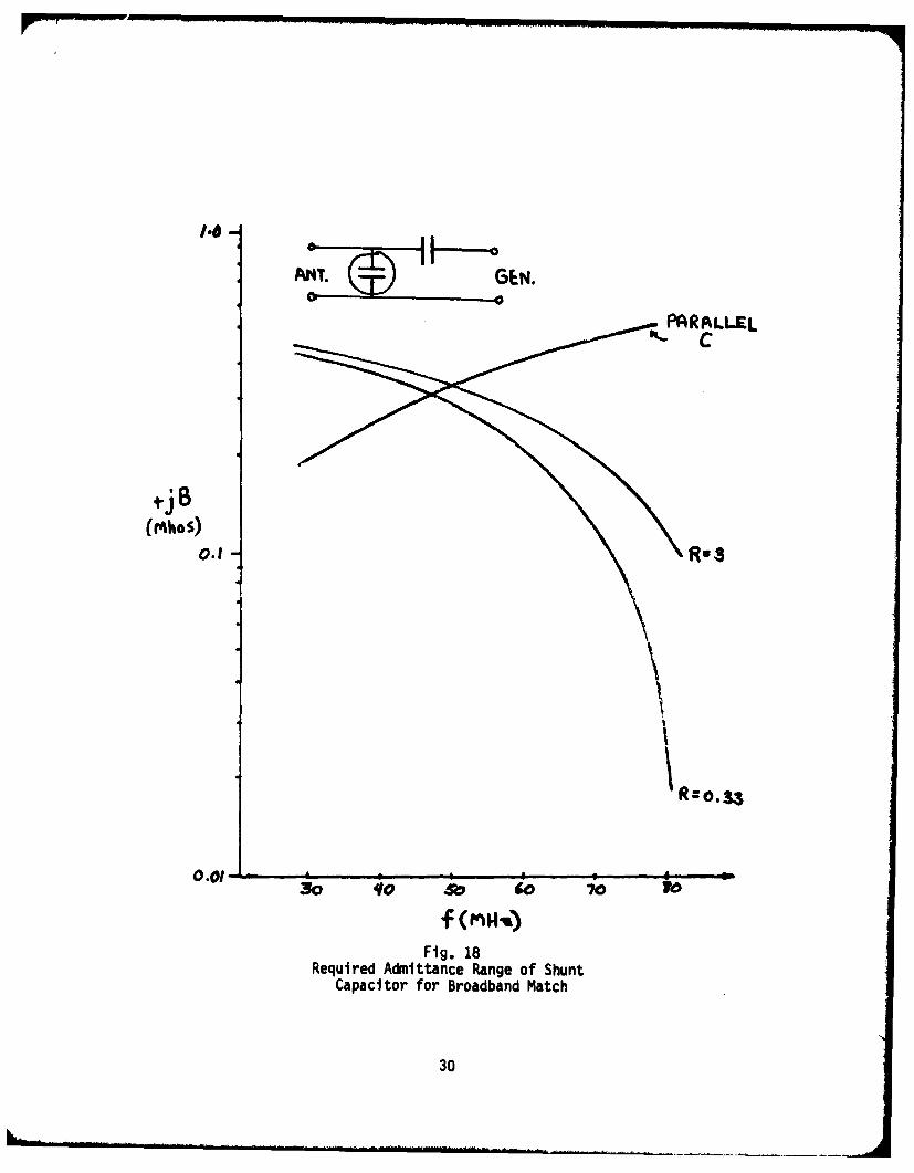
18 . Required admittance range of shunt capacitor for broad- 30band match
i
CONTENTS (CONT'D)
Page
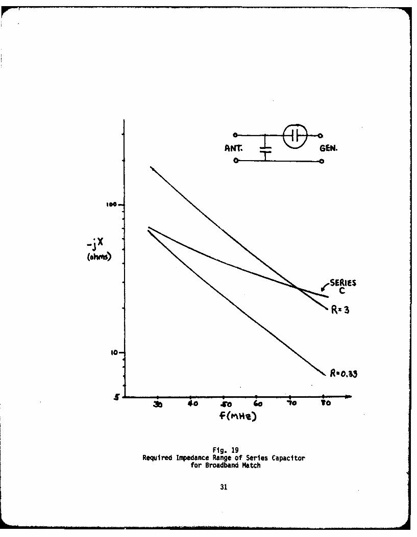
19. Required impedance range of series capacitor 31for broadband match
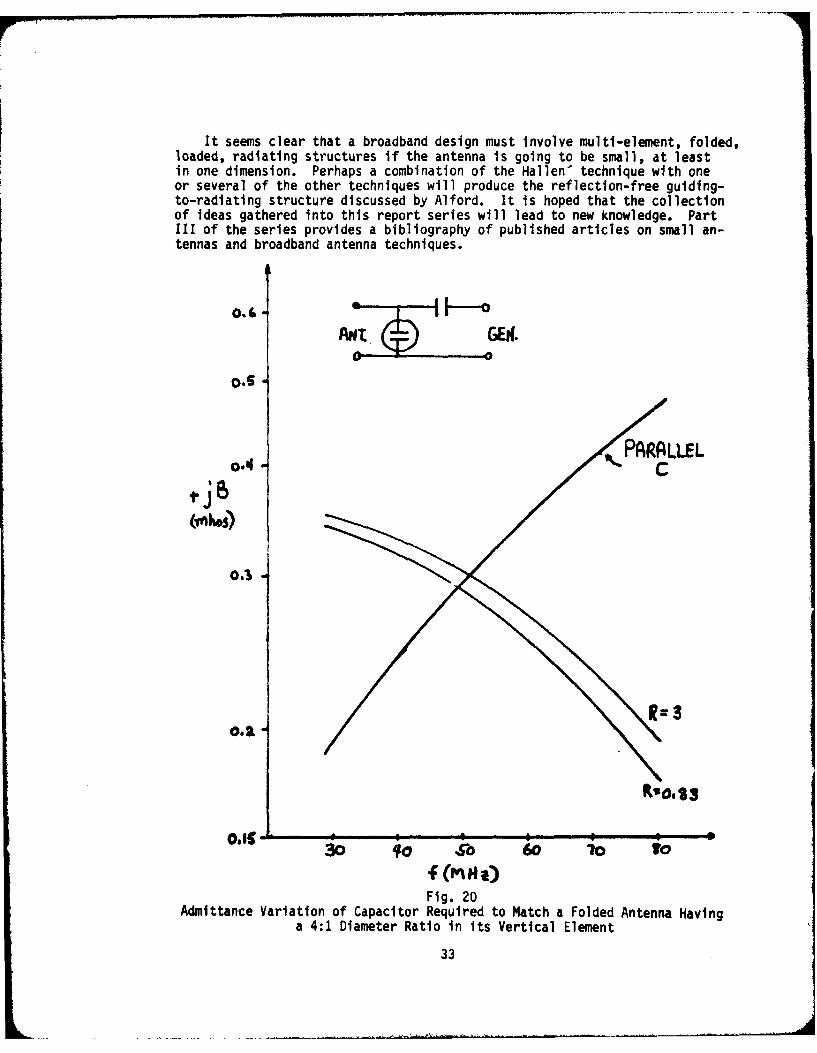
20. Admittance variation of capacitor required to 33match a folded antenna having a 4:1 diameterratio in its vertical element
21. Numerical model used for parasite loaded dipole 34
22. Calculated impedance variation of parasite-loaded dipole 35
LIST OF TABLES
1. Calculated Input Impedance 36
iii
LOW-PROFILE ANTENNA PERFORMANCE STUDY
PART II: BROADBAND ANTENNA TECHNIQUES SURVEY
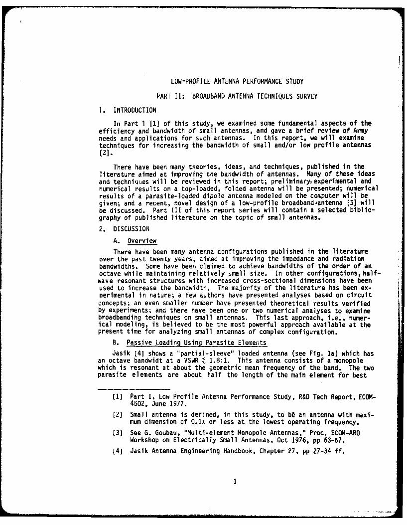
1. INTRODUCTION
In Part 1 [1] of this study, we examined some fundamental aspects of theefficiency and bandwidth of small antennas, and gave a brief review of Armyneeds and applications for such antennas. In this report, we will examinetechniques for increasing the bandwidth of small and/or low profile antennas[2].
There have been many theories, ideas, and techniques, published in theliterature aimed at improving the bandwidth of antennas. Many of these ideasand techniques will be reviewed in this report; preliminary, experimental andnumerical results on a top-loaded, folded antenna will be presented; numericalresults of a parasite-loaded dipole antenna modeled on the conputer will begiven; and a recent, novel design of a low-profile broadband4antenna [3] willbe discussed. Part III of this report series will contain a selected biblio-graphy of published literature on the topic of small antennas.
2. DISCUSSION
A. Overview
There have been many antenna configurations published in the literatureover the past twenty years, aimed at improving the impedance and radiationbandwidths. Some have been claimed to achieve bandwidths of the order of anoctave while maintaining relatively bmall size. In other configurations, half-wave resonant structures with increased cross-sectional dimensions have beenused to increase the bandwidth. The majority of the literature has been ex-oerimental in nature; a few authors have presented analyses based on circuitconcepts; an even smaller number have presented theoretical results verifiedby experiments; and there have been one or two numerical analyses to examinebroadbanding techniques on small antennas. This last approach, i.e., numer-ical modeling, is believed to be the most powerful approach available at thepresent time for analyzing small antennas of complex configuration.
B. Passive Loading Using Parasite Elements
Jasik (4] shows a "partial-sleeve" loaded antenna (see Fig. la) which hasan octave bandwidt at a VSWR ^ 1.8:1. This antenna consists of a monopolewhich is resonant at about the geometric mean frequency of the band. The twoparasite elements are about half the length of the main element for best
[1] Part I, Low Profile Antenna Performance Study, R&D Tech Report, ECOM-4502, June 1977.
[2] Small antenna is defined, in this study, to bb an antenna with maxi-mum dimension of 0.1X or less at the lowest operating frequency.
[3] See G. Goubau, "Multi-element Monopole Antennas," Proc. ECOM-AROWorkshop on Electrically Small Antennas, Oct 1976, pp 63-67.
[4] Jasik Antenna Engineering Handbook, Chapter 27, pp 27-34 ff.
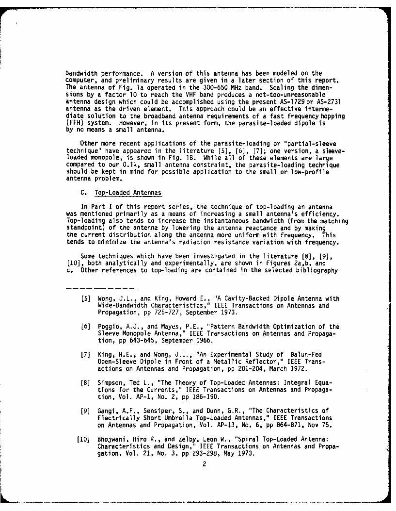
bandwidth performance. A version of this antenna has been modeled on thecomputer, and preliminary results are given in a later section of this report.The antenna of Fig. la operated in the 300-650 MHz band. Scaling the dimen-sions by a factor 10 to reach the VHF band produces a not-too-unreasonableantenna design which could be accomplished using the present AS-1729or AS-2731antenna as the driven element. This approach could be an effective interme-diate solution to the broadband antenna requirements of a fast frequency hopping(FFH) system. However, in its present form, the parasite-loaded dipole isby no means a small antenna.
Other more recent applications of the parasite-loading or "partial-sleevetechnique" have appeared in the literature [5], [6], [7]; one version, a sleeve-loaded monopole, is shown in Fig. lB. While all of these elements are largecompared to our O.lX, small antenna constraint, the parasite-loading techniqueshould be kept in mind for possible application to the small or low-profileantenna problem.
C. Top-Loaded Antennas
In Part I of this report series, the technique of top-loading an antennawas mentioned primarily as a means of increasing a small antenna's efficiency.Top-loading also tends to increase the instantaneous bandwidth (from the matchingstandpoint) of the antenna by lowering the antenna reactance and by makingthe current distribution along the antenna more uniform with frequency. Thistends to minimize the antenna's radiation resistance variation with frequency.
Some techniques which have been investigated in the literature [8], [9],[10], both analytically and experimentally, are shown in Figures 2a,b, andc. Other references to top-loading are contained in the selected bibliography
[5] Wong, J.L., and King, Howard E., "A Cavity-Backed Dipole Antenna withWide-Bandwidth Characteristics," IEEE Transactions on Antennas andPropagation, pp 725-727, September 1973.
[6] Poggio, A.J., and Mayes, P.E., "Pattern Bandwidth Optimization of theSleeve Monopole Antenna," IEEE Trarsactions on Antennas and Propaga-tion, pp 643-645, September 1966.
[7] King, H.E., and Wong, J.L., "An Experimental Study of Balun-FedOpen-Sleeve Dipole in Front of a Metallic Reflector," IEEE Trans-actions on Antennas and Propagation, pp 201-204, March 1972.
[8] Simpson, Ted L., "The Theory of Top-Loaded Antennas: Integral Equa-tions for the Currents," IEEE Transactions on Antennas and Propaga-tion, Vol. AP-1, No. 2, pp 186-190.
[9] Gangi, A.F., Sensiper, S., and Dunn, G.R., "The Characteristics ofElectrically Short Umbrella Top-Loaded Antennas," IEEE Transactionson Antennas and Propagation, Vol. AP-13, No. 6, pp 864-871, Nov 75.
[10] Bhojwani, Hiro R., and Zelby, Leon W., "Spiral Top-Loaded Antenna:Characteristics and Design," IEEE Transactions on Antennas and Propa-gation, Vol. 21, No. 3, pp 293-298, May 1973.
2
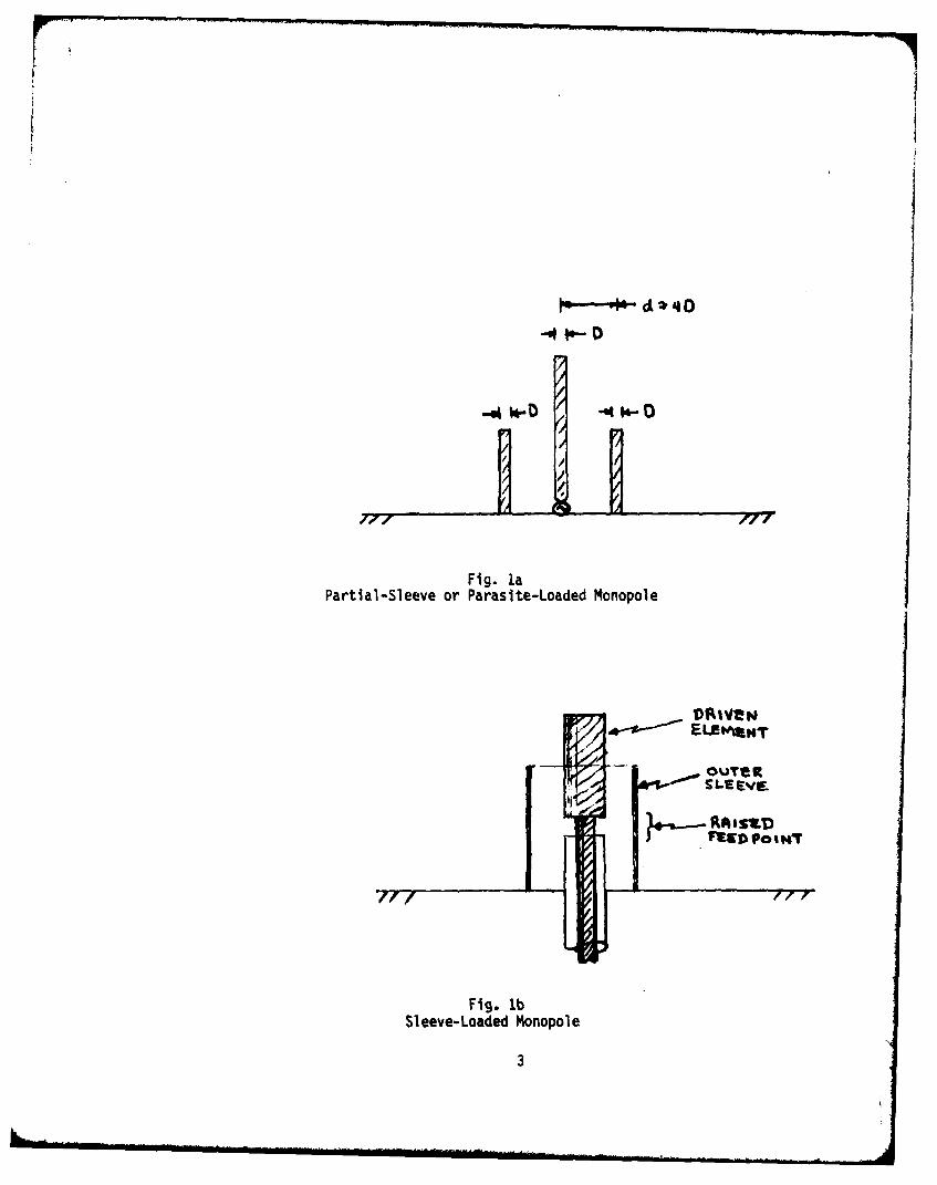
Fig. laPartial-Sleeve or Parasite-Loaded Monopole
Fig. lbSileeve-Loadedt Monopol e
3
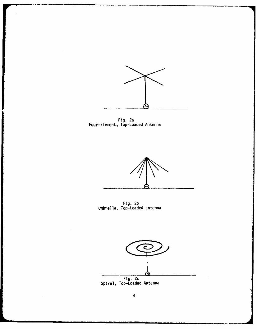
Fig. 2aFour-Element, Top-Loaded Antenna
Fig. 2bUmbrella, Top-Loaded antenna
Fig. 2cSpiral, Top-Loaded Antenna
4
given in Part 3 of this study. In the cited analytical studies, approximatenumerical techniques are employed to solve the integral equations for the cur-rents. The top-loading techniques of Figures 2b and c were originally inves-tigated to improve LF and VLF antennas where, because of the large wavelengthsinvolved, the O.l size criterion is easily adhered to. However, these tech-niques have been applied at higher frequencies to make small or lowzprofileantennas and so, should be kept in mind as useful techniques for VHF applica-tions. The zechnique of Fig. 2c, in particular, can be used to achieve reso-nance in a small structure, a desirable condition for good efficiency.
D. Electrically Thick Antennas
It is well known that increasing the thickness or diameter of a wire an-tenna tends to lower the Q which is an indication of an improvement in band-width. Quantitatively, thickening tends to lower the inductance of the an-tenna, thereby increasing the stored magnetic energy in the system. Thus,thedifference between electric and magnetic energy is minimized. At the sametime, the input resistance variation with frequency is minimized, which isan indication that the current distribution on the antenna tenas to be moreuniform.
The theory of the electrically thick monopole is available in the litera-ture [11], [12]. Numerical methods have also been applied to the solutionof the electrically thick antenna problem; in one case, in particular [13],the problem of the optimum shape for maximum bandwidth has been addressed.Fig. 3a shows a resulting broadband configuration which, however, tends to be
Fig. 3aBulb-Dipole Geometry for a Broadband Antenna
[11] Chang, David C., "On the Electrically Thick Monopole Part I-Theo-retical Solution," IEEE Transactions on Antennas and PropagationVol. AP-16, No. 1, pp 58-64, January 1968.
[12] Chang, David C., "On the Electrically Thick Monopole," Part II, Ex-perimental Study, IEEE Transactions on Antennas and Propagation,Vol. AP-16, No. 1, pp 64-71, January 1968.
[13] Kalafus, Rudolph M., "Broad-Band Dipole Design Using the Method ofMoments," IEEE Transactions on Antennas and Propagation, pp 771-773,November 1971.
5
7--
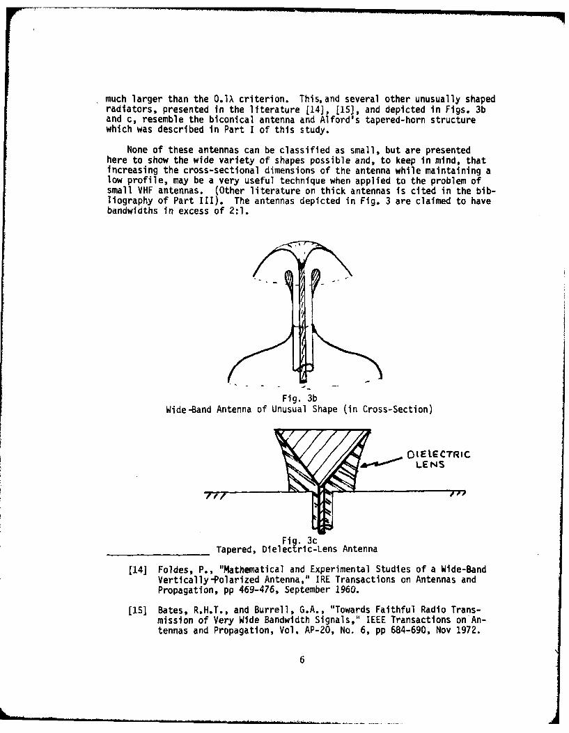
much larger than the O.I criterion. This,and several other unusually shapedradiators, presented in the literature [141, [15], and depicted in Figs. 3band c, resemble the biconical antenna and Alford's tapered-horn structurewhich was described in Part I of this study.
None of these antennas can be classified as small, but are presentedhere to show the wide variety of shapes possible and, to keep in mind, thatincreasing the cross-sectional dimensions of the antenna while maintaining alow profile, may be a very useful technique when applied to the problem ofsmall VHF antennas. (Other literature on thick antennas is cited in the bib-liography of Part III). The antennas depicted in Fig. 3 are claimed to havebandwiaths in excess of 2:1.
Fig. 3bWide-Band Antenna of Unusual Shape (in Cross-Section)
01 EIECTRiCLE NS
Fig. 3cTapered, Dielectric-Lens Antenna
[14] Foldes, P., "Mathematical and Experimental Studies of a Wide-BandVertically-Polarized Antenna," IRE Transactions on Antennas andPropagation, pp 469-476, September 1960.
[15] Bates, R.H.T., and Burrell, G.A., "Towards Faithful Radio Trans-mission of Very Wide Bandwidth Signals," IEEE Transactions onAn-tennas and Propagation, Vol. AP-20, No. 6, pp 684-690, Nov 1972.
6
E. Folded Antennas
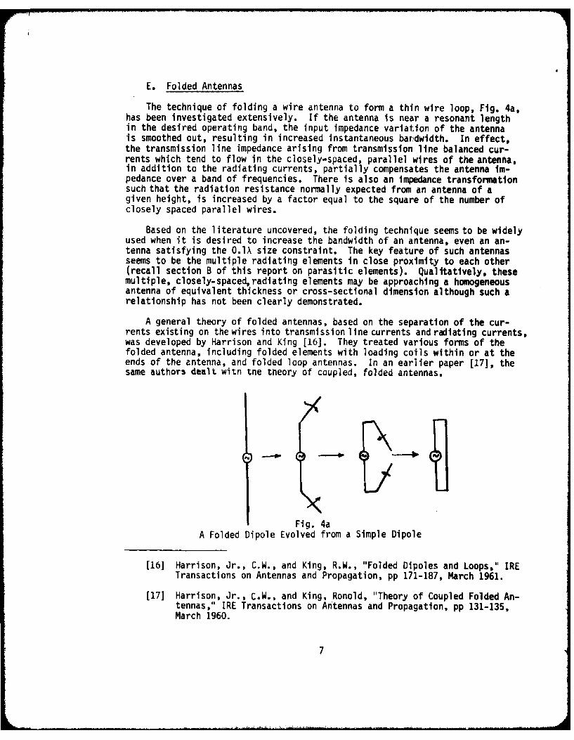
The technique of folding a wire antenna to form a thin wire loop, Fig. 4a,has been investigated extensively. If the antenna is near a resonant lengthin the desired operating band, the input impedance variation of the antennais smoothed out, resulting in increased instantaneous bardwidth. In effect,the transmission line impedance arising from transmission line balanced cur-rents which tend to flow in the closely-spaced, parallel wires of the antenna,in addition to the radiating currents, partially compensates the antenna im-pedance over a band of frequencies. There is also an impedance transformationsuch that the radiation resistance normally expected from an antenna of agiven height, is increased by a factor equal to the square of the number ofclosely spaced parallel wires.
Based on the literature uncovered, the folding technique seems to be widelyused when it is desired to increase the bandwidth of an antenna, even an an-tenna satisfying the O.lX size constraint. The key feature of such antennasseems to be the multiple radiating elements in close proximity to each other(recall section B of this report on parasitic elements). Qualitatively, thesemultiple, closely-spaced, radiating elements may be approaching a homogeneousantenna of equivalent thickness or cross-sectional dimension although such arelationship has not been clearly demonstrated.
A general theory of folded antennas, based on the separation of the cur-rents existing on thewires into transmission line currents and raiating currents,was developed by Harrison and King [16]. They treated various forms of thefolded antenna, including folded elements with loading coils within or at theends of the antenna, and folded loop antennas. In an earlier paper (17], thesame authors dealt witn tne theory of coupled, folded antennas.
pg(
Fig. 4aA Folded Dipole Evolved from a Simple Dipole
[16] Harrison, Jr., C.W., and King, R.W., "Folded Dipoles and Loops," IRETransactions on Antennas and Propagation, pp 171-187, March 1961.
[17] Harrison, Jr., C.W., and King, Ronold, "Theory of Coupled Folded An-tennas," IRE Transactions on Antennas and Propagation, pp 131-135,March 1960.
7
Two other papers [18], [19], deal with changes in the electrical charac-teristics caused by varying the physical parameters of the folded antenna,such as element length, diameter, and spacing. It is interesting to notethat one of the articles [18] discusses the use of the folding principle forsmall antennas, notes the importance of designing some of the tuning andmatching network elements into the radiating structure, and uses the shuntinput L-network, discussed in Part I of this study, to achieve better band-width characteristics.
The other paper [19] discusses the bandwidth possibilities of the foldeddipole and lists some general conclusions regarding parameter variations;i.e., increased spacing between the conductors and increased conductor sizeimprove the bandwidth, in general. Note, however, that only X/4 elementlengths were considered in this paper.
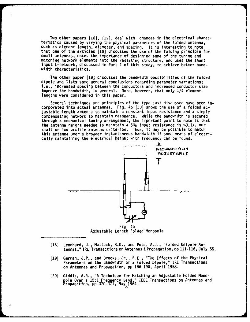
Several techniques and principles of the type just discussed have been in-corporated into actual antennas. Fig. 4b [20] shows the use of a folded ad-justable-length antenna to maintain a constant input resistance and a simplecompensating network to maintain resonance. While the bandwidth is securedthrough a mechanical tuning arrangement, the important point to note is thatthe antenna height needed to maintain a 50Q input resistance is O ).Il, oursmall or low profile antenna criterion. Thus, it may be possible to matchthis antenna over a broader instantaneous bandwidth if some means of electri-cally maintaining the electrical height with frequency can be found.
T
Fig. 4bAdjustable Length Folded Monopole
[18] Leonhard, J., Mattuck, R.D., and Pote, A.J., "Folded Unipole An-tennas," IRE Transactions on Antennas & Propagation, pp 111-116, July 55.
[19] German, J.P., and Brooks, Jr., F.E., "The Effects of the PhysicalParameters on the Bandwidth of a Folded Dipole," IRE Transactionson Antennas and Propagation, pp 186-190, April 1958.
[201 Giddis, A.R., "A Technique for Matching an Adjustable Folded Mono-pole Over a 15:1 Frequency Band," IEEE Transactions on Antennas andropagation, pp 370- 71, May8 1964.
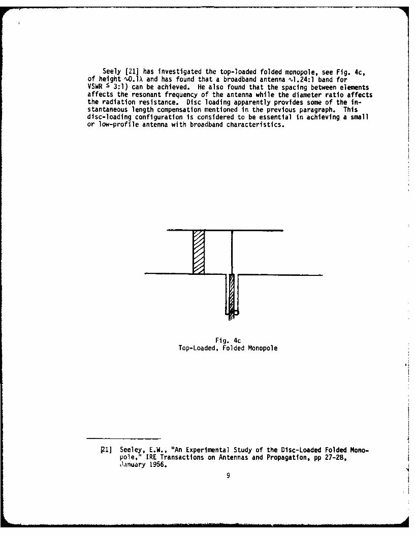
Seely [21] has investigated the top-loaded folded monopole, see Fig. 4c,of height ,.O.lX and has found that a broadband antenna "1.24:1 band forVSWR S 3:1) can be achieved. He also found that the spacing between elementsaffects the resonant frequency of the antenna while the diameter ratio affectsthe radiation resistance. Disc loading apparently provides some of the in-stantaneous length compensation mentioned in the previous paragraph. Thisdisc-loading configuration is considered to be essential in achieving a smallor low-profile antenna with broadband characteristics.
Fig. 4cTop-Loaded, Folded Monopole
J1] Seeley, E.W., "An Experimental Study of the Disc-Loaded Folded Mono-pole," IRE Transactions on Antennas and Propagation, pp 27-28,Jainuary 1956.
9
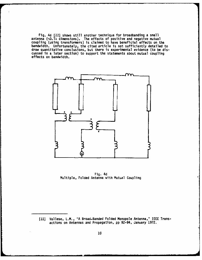
Fig. 4d [22] shows still another technique for broadbandlng a smallantenna (O.IX dimensions). The effects of positive and negative mutualcoupling (using transformers) is claimed to have beneficial effects on thebandwidth. Unfortunately, the cited article is not sufficiently detailed todraw quantitative conclusions, but there is experimental evidence (to be dis-cussed in a later section) to support the statements about mutual couplingeffects on bandwidth.
Fig. 4dMultiple, Folded Antenna with Mutual Coupling
[22) Vallese, L.M., "A Broad-Banded Folded Monopole Antenna," IEEE Trans-actions on Antennas and Propagation, pp 92-94, January 1972.
10
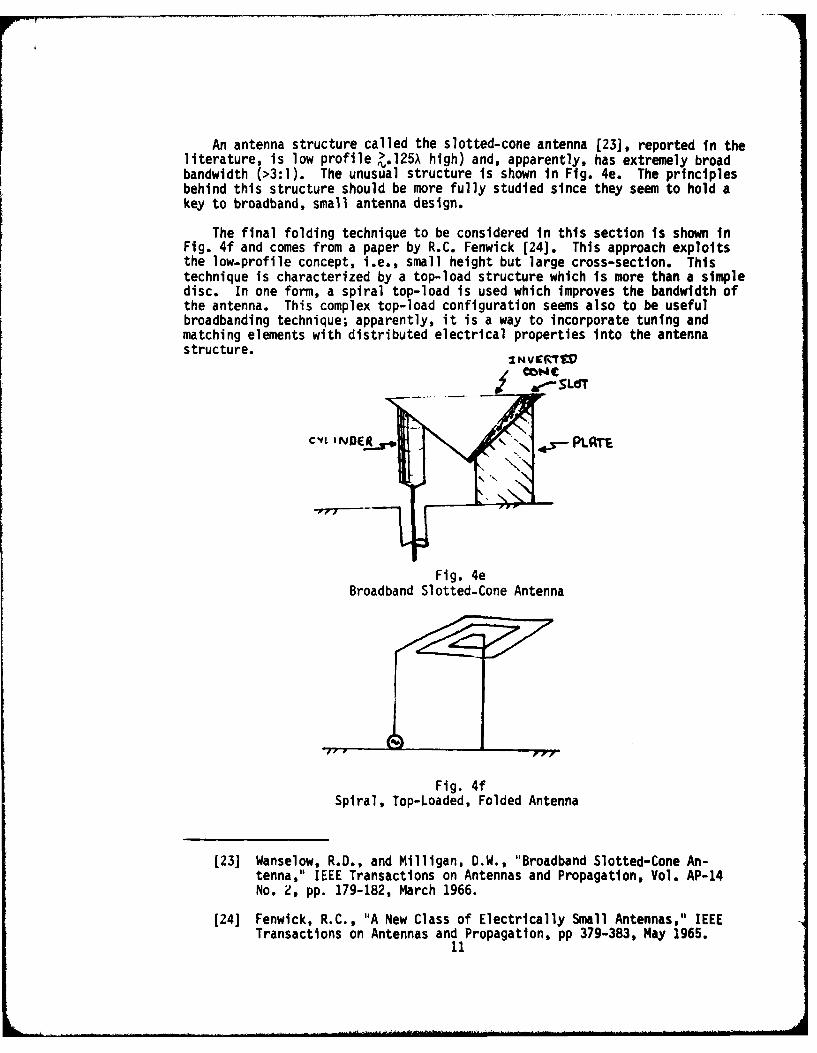
An antenna structure called the slotted-cone antenna [23), reported in theliterature, is low profile ".125A high) and, apparently, has extremely broadbandwidth (>3:1). The unusual structure is shown in Fig. 4e. The principlesbehind this structure should be more fully studied since they seem to hold akey to broadband, small antenna design.
The final folding technique to be considered in this section is shown inFig. 4f and comes from a paper by R.C. Fenwick [24]. This approach exploitsthe low-profile concept, i.e., small height but large cross-section. Thistechnique is characterized by a top-load structure which is more than a simpledisc. In one form, a spiral top-load is used which improves the bandwidth ofthe antenna. This complex top-load configuration seems also to be usefulbroadbanding technique; apparently, it is a way to incorporate tuning andmatching elements with distributed electrical properties Into the antennastructure. I4VertItvy ONC
C*4L~ I "_R%*N PLR
Fig. 4eBroadband Slotted-Cone Antenna
Fig. 4fSpiral, Top-Loaded, Folded Antenna
[23] Wanselow, R.D., and Milligan, D.W., "Broadband Slotted-Cone An-tenna," IEEE Transactions on Antennas and Propagation, Vol. AP-14No. 2, pp. 179-182, March 1966.
[24] Fenwick, R.C., "A New Class of Electrically Small Antennas," IEEETransactions on Antennas and Propagation, pp 379-383, May 1965.
11
F. Conjugate Reactance Loading
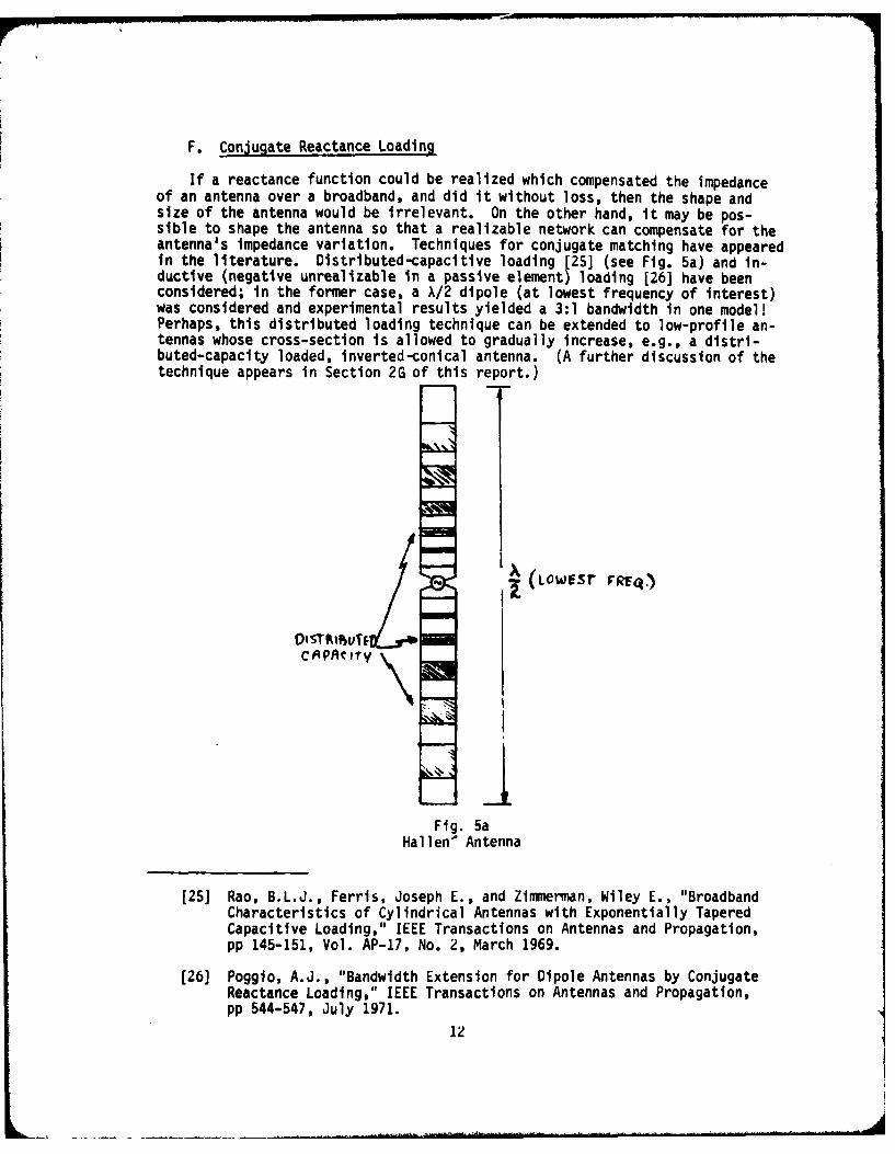
If a reactance function could be realized which compensated the impedanceof an antenna over a broadband, and did it without loss, then the shape andsize of the antenna would be irrelevant. On the other hand, it may be pos-sible to shape the antenna so that a realizable network can compensate for theantenna's impedance variation. Techniques for conjugate matching have appearedin the literature. Distributed-capacitive loading [25] (see Fig. 5a) and in-ductive (negative unrealizable in a passive element) loading [26] have beenconsidered; in the former case, a A/2 dipole (at lowest frequency of interest)was considered and experimental results yielded a 3:1 bandwidth in one model!Perhaps, this distributed loading technique can be extended to low-profile an-tennas whose cross-section is allowed to gradually increase, e.g., a distri-buted-capacity loaded, inverted-conical antenna. (A further discussion of thetechnique appears in Section 2G of this report.)
- Low~sr FREQ)
Fig. 5aHallen' Antenna
[25] Rao, B.L.J., Ferris, Joseph E., and Zimmerman, Wiley E., "BroadbandCharacteristics of Cylindrical Antennas with Exponentially TaperedCapacitive Loading," IEEE Transactions on Antennas and Propagation,pp 145-151, Vol. AP-17, No. 2, March 1969.
[26] Poggio, A.J., "Bandwidth Extension for Dipole Antennas by ConjugateReactance Loading," IEEE Transactions on Antennas and Propagation,pp 544-547, July 1971.
12
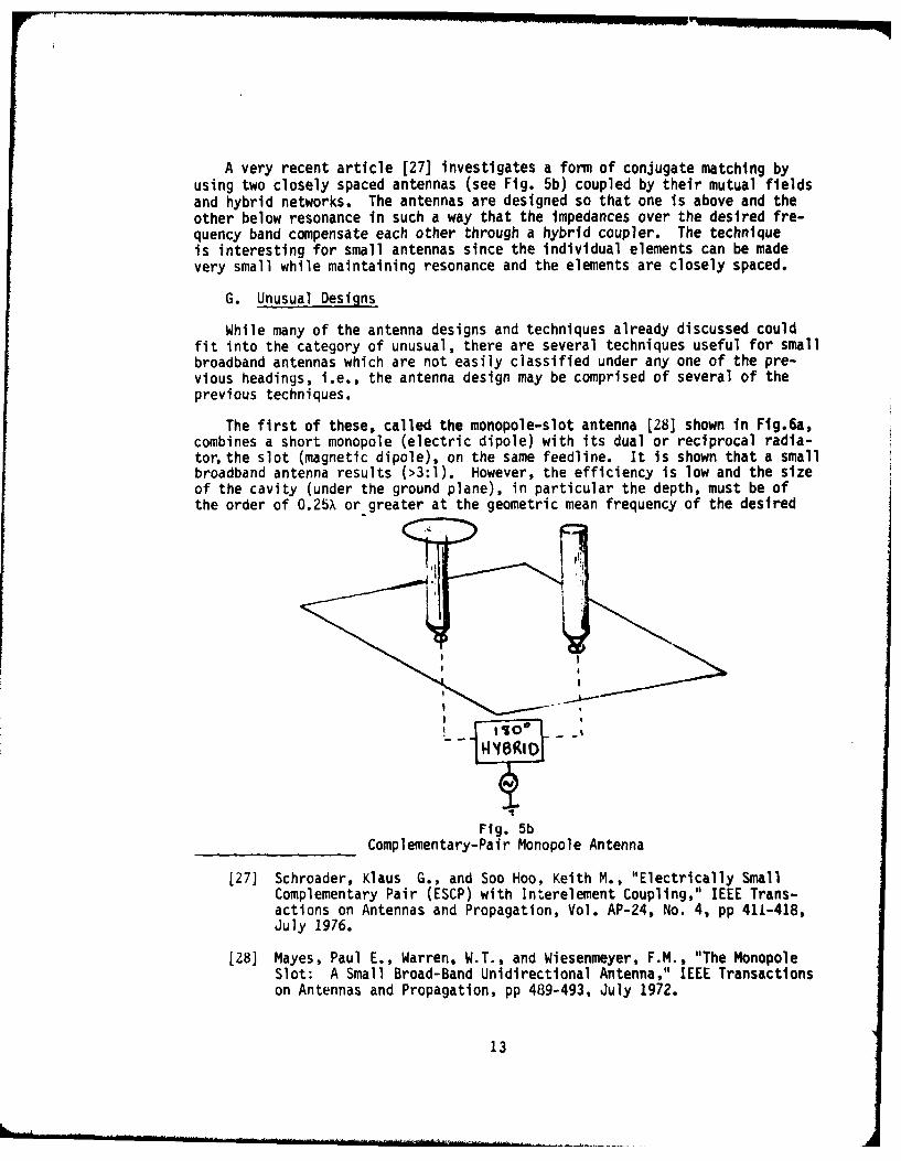
A very recent article [27] investigates a form of conjugate matching byusing two closely spaced antennas (see Fig. 5b) coupled by their mutual fieldsand hybrid networks. The antennas are designed so that one is above and theother below resonance in such a way that the impedances over the desired fre-quency band compensate each other through a hybrid coupler. The techniqueis interesting for small antennas since the individual elements can be madevery small while maintaining resonance and the elements are closely spaced.
G. Unusual Designs
While many of the antenna designs and techniques already discussed couldfit into the category of unusual, there are several techniques useful for smallbroadband antennas which are not easily classified under any one of the pre-vious headings, i.e., the antenna design may be comprised of several of theprevious techniques.
The first of these, called the monopole-slot antenna [28] shown in Fig.6a,combines a short monopole (electric dipole) with its dual or reciprocal radia-tor, the slot (magnetic dipole), on the same feedline. It is shown that a smallbroadband antenna results (>3:1). However, the efficiency is low and the sizeof the cavity (under the ground plane), in particular the depth, must be ofthe order of 0.25X or greater at the geometric mean frequency of the desired
I-o
Fig. 5bComplementary-Pair Monopole Antenna
[27] Schroader, Klaus G., and Soo Hoo, Keith M., "Electrically SmallComplementary Pair (ESCP) with Interelement Coupling," IEEE Trans-actions on Antennas and Propagation, Vol. AP-24, No. 4, pp 411-418,July 1976.
[28] Mayes, Paul E., Warren, W.T., and Wiesenmeyer, F.M., "The MonopoleSlot: A Small Broad-Band Unidirectional Antenna," IEEE Transactionson Antennas and Propagation, pp 489-493, July 1972.
13
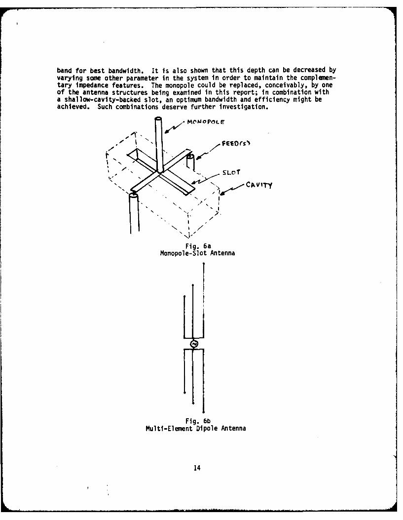
band for best bandwidth. It is also shown that this depth can be decreased byvarying some other parameter in the system in order to maintain the complemen-tary impedance features. The monopole could be replaced, conceivably, by oneof the antenna structures being examined in this report; in combination witha shallow-cavity-backed slot, an optimum bandwidth and efficiency might beachieved. Such combinations deserve further investigation.
'j7 MOMOPOL E
sFESU"
. " SLoT
".C ., CvTy". t
Fig. 6aMonopole-Slot Antenna
Fig. 6bMulti-Element Dipole Antenna
14
- iO
The final technique to be considered is the multi-element dipole antenna[29] shown in Fig. 6b. Several closely spaced elements of different lengthsdriven by the same generator are shown to produce an antenna with a broadbandinput impedance characteristic. The multi-element feature has appeared in ourprevious reviews, but here all of the elements are driven. The lengths of theelements are such that they resonate somewhere in the desired band; using thecoupling between these resonant antennas, a change in bandwidth can be affected.It is expected that the elements can be loaded to shorten their overall length,thus fitting into the O.lA criterion; and perhaps this combination of loaded,driven elements at different resonant frequencies, closely spaced to take ad-vantage of mutual coupling effects could lead to a broadband antenna of smallsize. It should also be determined whether this multi-element technique isor is not equivalent to a thick antenna of comparable dimensions.
3. EXPERIMENTAL RESULTS
The folded-antenna configuration appears to have potentially broadbandcharacteristics. We have seen in the previous sections of this report thattheory and experiments support this observation. In the following sections,we will present some experimental data to further strengthen this support.While much of the information to be presented is not new, it will be inform-ative to review it from the standpoint of antenna bandwidth.
A. Stubs and Loops
We will start with measurements of:
(1) A small stub;
(2) a small loop (folded antenna);
(3) a stub with a top-load; and,
(4) a folded, top-loaded antenna.
Measurements of the input impedance of these different types of antennasover the 200-400 MHz frequency range are shown in Fig. 7. These measurementswere made with a swept frequency network analyser. The antennas were mountedon a four-foot square metal ground plane and the measured impedances were ref-erenced to the base of the antenna just under the ground plane. Errors intro-duced by the measurement system were estimated by making a swept-frequency im-pedance measurement of a short circuit placed at the point where the antennawould ordinarily be connected. A perfect measurement would result in a singledot occurring at the 0 impedance point on the Smith Chart. The measured shortcircuit Lmpedance over the 200-400 MHz range is shown in Fig. 7 as the curvemarked CO. It can be seen that there were residual errors in the system, butthe magnitude of these errors was considered small enough for our intendedpurpose, i.e., to predict bandwidth trends. Further compensation of the meas-urement system would be necessary to obtain more accurate impedance data.
[29] Chowdhury, S.K., "Impedance of Mlti-element Dipoles," IEEE Trans-
actions on Antennas and Propagation, pp 682-684, September 1971.
15
.J
" \ i Stub..... .I L 2. Loop
3. Top-Loaded Stub4. Top-Loaded Loop5. Short-Ckt Trace
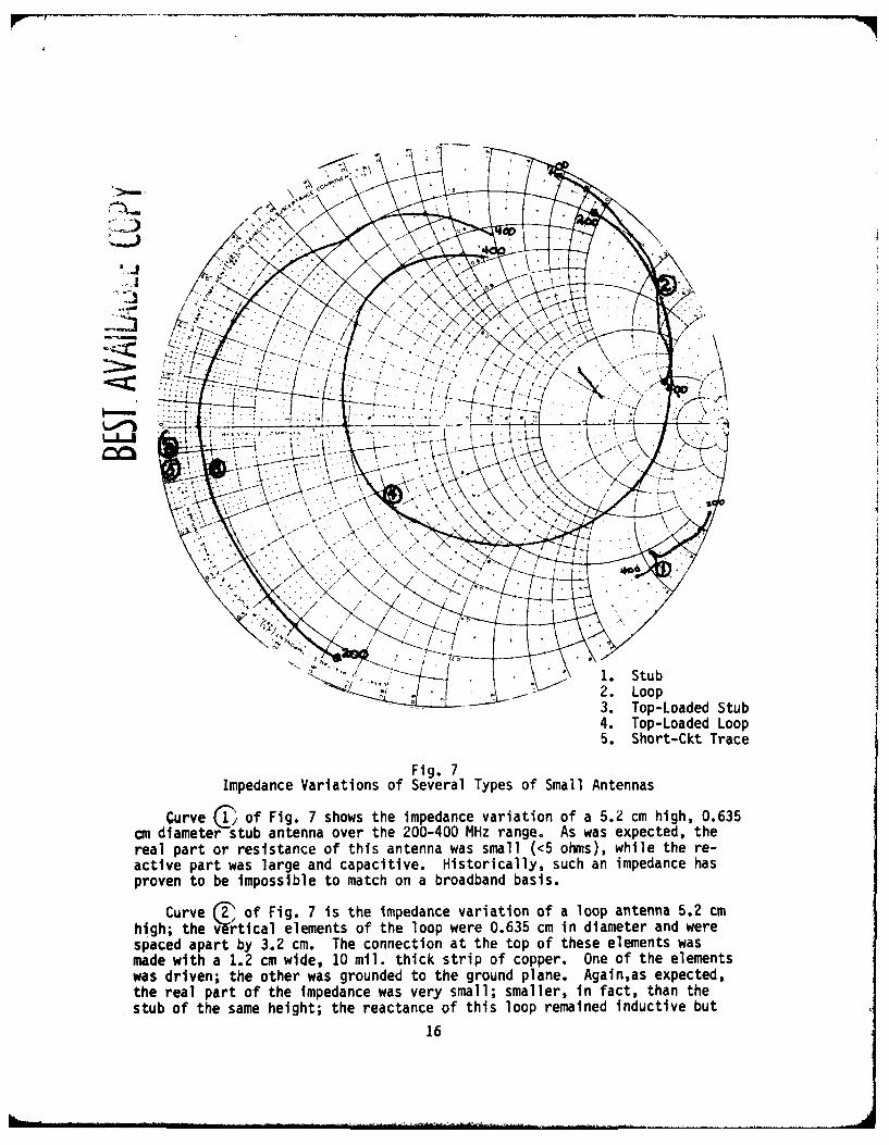
Fig. 7Impedance Variations of Several Types of Small Antennas
Curve T of Fig. 7 shows the impedance variation of a 5.2 cm high, 0.635cm diameter stub antenna over the 200-400 MHz range. As was expected, thereal part or resistance of this antenna was small (<5 ohms), while the re-active part was large and capacitive. Historically, such an impedance hasproven to be impossible to match on a broadband basis.
Curve ( of Fig. 7 is the impedance variation of a loop antenna 5.2 cmhigh; the v-rtical elements of the loop were 0.635 cm in diameter and werespaced apart by 3.2 cm. The connection at the top of these elements wasmade with a 1.2 cm wide, 10 mil. thick strip of copper. One of the elementswas driven; the other was grounded to the ground plane. Again,as expected,the real part of the impedance was very small; smaller, in fact, than thestub of the same height; the reactance of this loop remained inductive but
16
. . . .. . . ......... . . . . ...... . . ... I ..
varied over a wider range than the reactance variation of the stub. Ingeneral, this impedance variation would be impossible to compensate over abroadband using non-varying circuit elements.
Curve I of Fig. 7 shows the 5 cm high stub with a 14 x 14 cm copper plateas a capacitive top load. Several features of this curve are notable: 1)a resonance occurs in the structure at mid-band; 2) the resistance of thetop-loaded stub has not changed very much from that of the simple stub; and3) the reactance valueAnd variation has been reduced from that cf the plainstub. Although curve (3) appears to have a greater variation, it occurs onthe section of the Smit? chart where the reactance varies more slowly.
If we use the reactance variation as an indication of the potential band-width, i.e., large reactance variation - small bandwidth, small reactancevariation - large bandwidth, then the top-loaded stub has a greater instan-taneous bandwidth than the plain stub. The bandwidth criterion just estab-lished is justified on the basis that matching with fixed value circuit ele-ments can be accomplished over a band of frequencies when the reactive compo-nent of the impedance is a slowly varying function.
Curve (4) shows the impedance variation of a top-loaded, folded-monopoleantenna. I is a combination of the loop discussed previously and the 14cm square copperplate. There are several interesting features in this curve:1) two resonant points occurred; 2) at the higher frequencies, above 300 MHz,the real part increased substantially; and 3) the reactance variation in the300-400 MHz was markedly reduced. Based on the bandwidth criterion discussedabove, the top-loaded loop has a higher instantaneous bandwidth than the sim-ple loop.
A comparison of the bandwidth capabilities of the top-loaded stub andthe top-loaded loop indicates that the top-loaded loop has a higher instan-taneous bandwidth than the top-loaded stub at frequencies above 300 MHz.Below this frequency, the stub may have a slight advantage. The height ofthese small antennas at 300 MHz is 1/20X, half of our small antenna criterion.Thus, an increase in height of either antenna would improve the bandwidth.However, it appears that the configuration of a loop with a top-load is abasic step in the direction of a small antenna with a wide instantaneous band-width.
B. Top-Loaded Loop Antenna
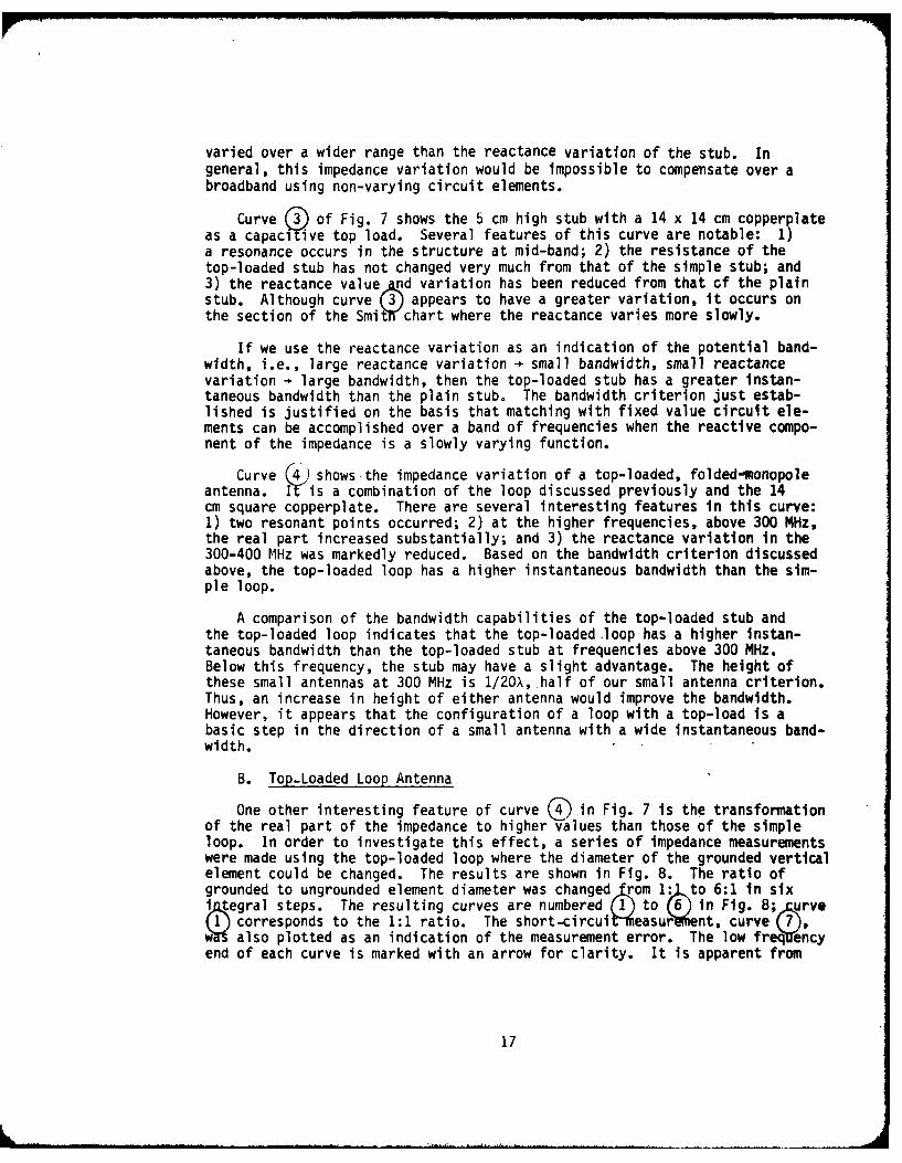
One other interesting feature of curve ( ) in Fig. 7 is the transformationof the real part of the impedance to higher values than those of the simpleloop. In order to investigate this effect, a series of impedance measurementswere made using the top-loaded loop where the diameter of the grounded verticalelement could be changed. The results are shown in Fig. 8. The ratio ofgrounded to ungrounded element diameter was changed krom 1:vXto 6:1 in sixijp~egral steps. The resulting curves are numbered (1) to (6) in Flg. 8; .urve(1)corresponds to the 1:1 ratio. The short-circultieasur Vient, curve (7),w also plotted as an indication of the measurement error. The low freq Uncyend of each curve is marked with an arrow for clarity. It is apparent from
17
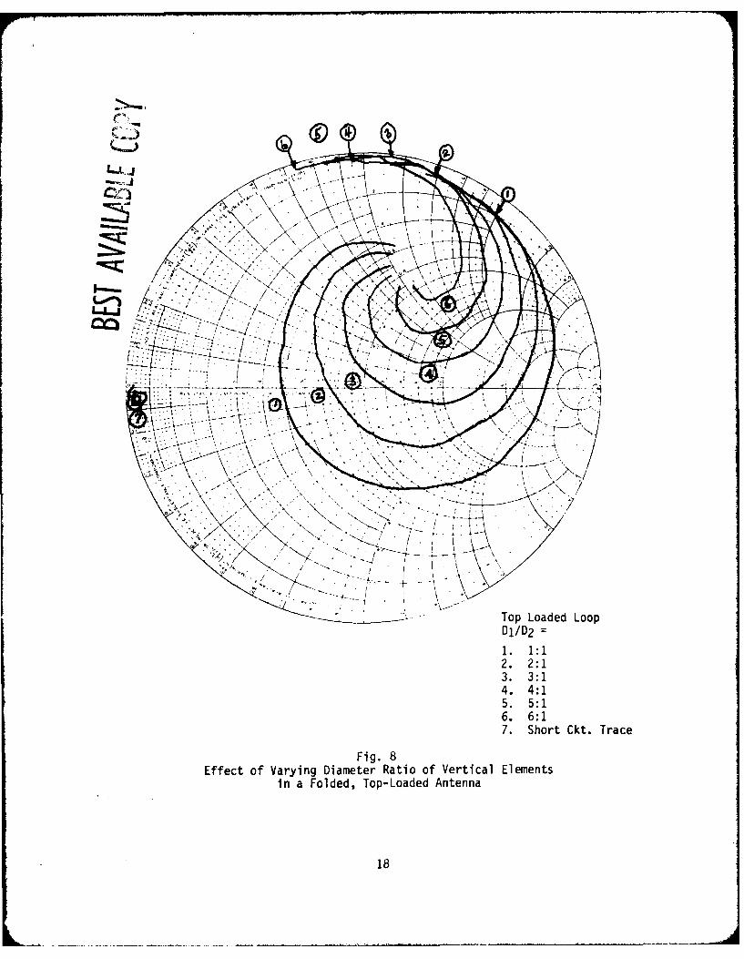
Top Loaded LoopDj/D 21. 1:12. 2:13. 3:14. 4:15. 5:16. 6:17. Short Ckt. Trace
Fig. 8Effect of Varying Diameter Ratio of Vertical Elements
in a Folded, Top-Loaded Antenna
18
the variations that an impedance transformation occurs, but it does not seemto be the N2:1 transformation which occurs in the half-wave, folded-dipoleantenna configuration (see Ref. 30). In fact, at the band edges, 200 and400 MHz, the transformation is less than a 1:1 transformation.
At 200 MHz, the resistance varies inversely with diameter ratio. It ap-pears, therefore, that the variation of the diameter in such a small struc-ture has a small transformation effect on the antenna input impedance andthe major effect of increasing the diameter is a reduction in the inductanceof the antenna.
However, it can be seen that a substantial transformatio 0has occurredwhen a comparison between the siiple loop impedance, curve (2) of Fig. 7,and the top-loaded loop, curve (4) of Fig. 7 is made. At th low frequencyend, the transformation is aboutm:1. At 400 MHz, there is n10:1 transform-ation for the real part of the impedance. The changes In the imaginary partof the impedance follow different transformation ratios.
C. The Goubau Antenna31
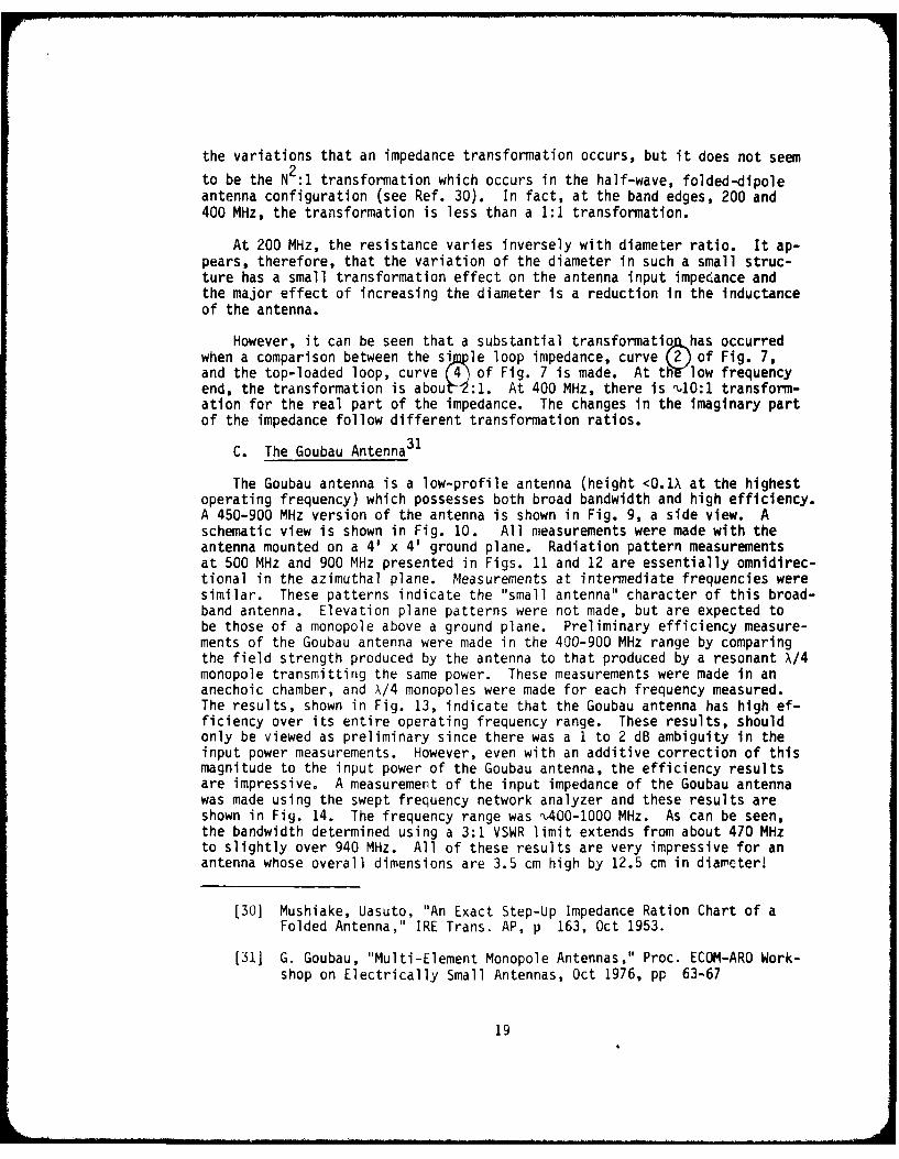
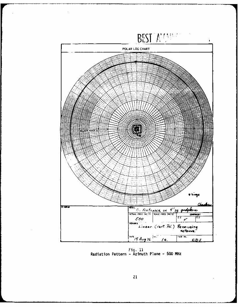
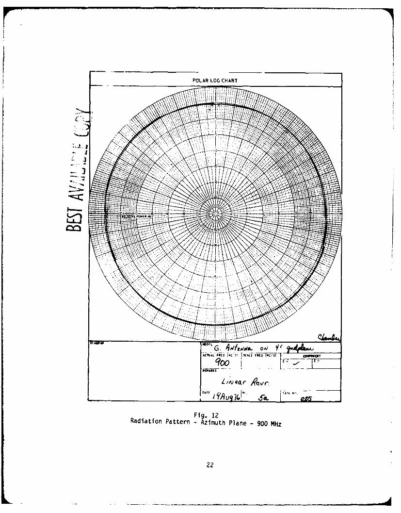
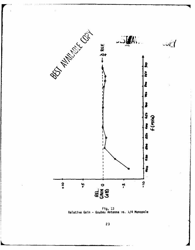
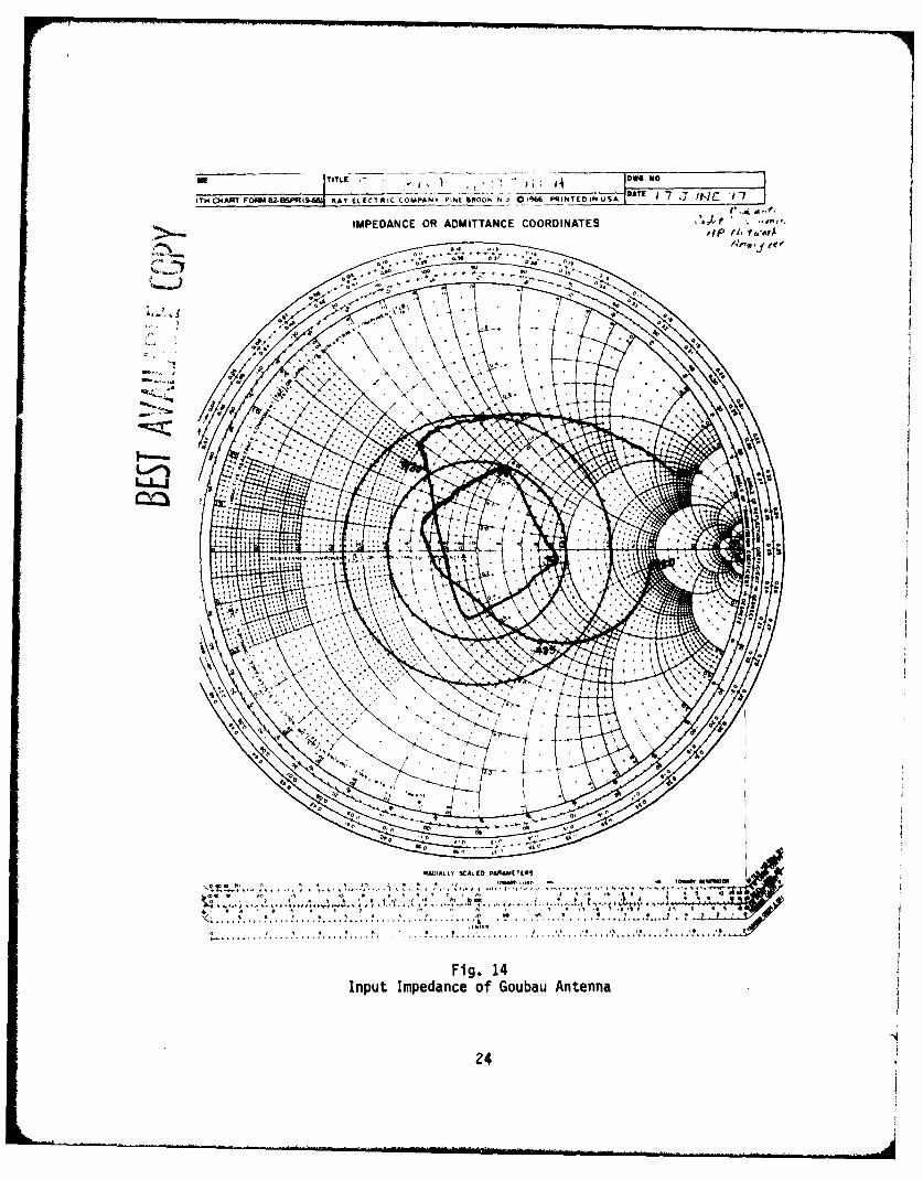
The Goubau antenna is a low-profile antenna (height <O.IX at the highestoperating frequency) which possesses both broad bandwidth and high efficiency.A 450-900 MHz version of the antenna is shown in Fig. 9, a side view. Aschematic view is shown in Fig. 10. All measurements were made with theantenna mounted on a 4' x 4' ground plane. Radiation pattern measurementsat 500 MHz and 900 MHz presented in Figs. 11 and 12 are essentially omnidirec-tional in the azimuthal plane. Measurements at intermediate frequencies weresimilar. These patterns indicate the "small antenna" character of this broad-band antenna. Elevation plane patterns were not made, but are expected tobe those of a monopole above a ground plane. Preliminary efficiency measure-ments of the Goubau antenna were made in the 400-900 MHz range by comparingthe field strength produced by the antenna to that produced by a resonant X/4monopole transmitting the same power. These measurements were made in ananechoic chamber, and X/4 monopoles were made for each frequency measured.The results, shown in Fig. 13, indicate that the Goubau antenna has high ef-ficiency over its entire operating frequency range. These results, shouldonly be viewed as preliminary since there was a 1 to 2 dB ambiguity in theinput power measurements. However, even with an additive correction of thismagnitude to the input power of the Goubau antenna, the efficiency resultsare impressive. A measurement of the input impedance of the Goubau antennawas made using the swept frequency network analyzer and these results areshown in Fig. 14. The frequency range was nu400-1000 MHz. As can be seen,the bandwidth determined using a 3:1 VSWR limit extends from about 470 MHzto slightly over 940 MHz. All of these results are very impressive for anantenna whose overall dimensions are 3.5 cm high by 12.5 cm in diarmeter!
[30] Mushiake, Uasuto, "An Exact Step-Up Impedance Ration Chart of aFolded Antenna," IRE Trans. AP, p 163, Oct 1953.
[311 G. Goubau, "Multi-Element Monopole Antennas," Proc. ECOM-ARO Work-shop on Electrically Small Antennas, Oct 1976, pp 63-67
19
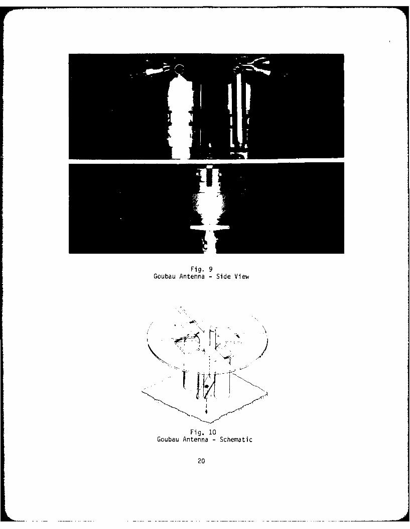
Fig. 9Goubau Antenna - Side View
Fig. 10Goubau Antenna - Schematic
20
____ ____ ___ BELST t
POLAR LOG CHART
ACTUJAL FIcO (Mc ( rCI F(O NC/S)
Fig. 11Radiation Pattern - Azimuth Plane - 500 MHz
21
POLAR LOG CHART
L-
AwwcihLiEQTM-(C-5 %CAL( FTO FMC/S N133
Fig. 12Radiation Pattern - Azimuth Plane - 900 MHz
22
k i
4.LLI
2
!r
I
I A
B 0.
!: 0
4I
Fig. 13
Relative Gain - loubau Antenna vss. X/4 Monopole
23
ITNQ4AWT FORM 62-OSPlI54G)l K.AY ELECTRIC COMPANY PIN( WtOOI' N J 19%6DT 7WJ
IMPEDANCE OR ADMITTANCE COORDINATES4r,*, t.eri~
2%
RADIALLV SCALED PARAMETERS
Fig. 14Input Impedance of Goubau Antenna
24
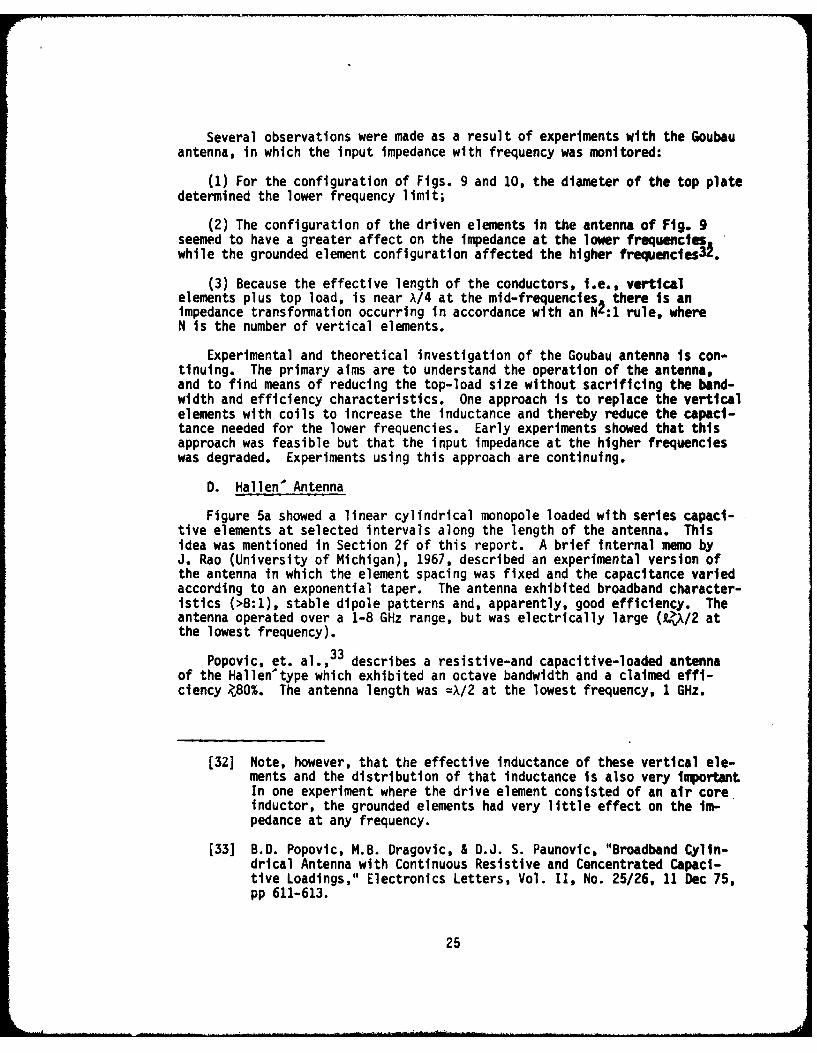
Several observations were made as a result of experiments with the Goubauantenna, in which the input impedance with frequency was monitored:
(1) For the configuration of Figs. 9 and 10, the diameter of the top platedetermined the lower frequency limit;
(2) The configuration of the driven elements in the antenna of Fig. 9seemed to have a greater affect on the impedance at the lower frequencieswhile the grounded element configuration affected the higher frequencies3l.
(3) Because the effective length of the conductors, i.e., verticalelements plus top load, is near A/4 at the mid-frequencies there is animpedance transformation occurring in accordance with an N2:1 rule, whereN is the number of vertical elements.
Experimental and theoretical investigation of the Goubau antenna is con-tinuing. The primary alms are to understand the operation of the antenna,and to find means of reducing the top-load size without sacrificing the band-width and efficiency characteristics. One approach is to replace the verticalelements with coils to increase the inductance and thereby reduce the capaci-tance needed for the lower frequencies. Early experiments showed that thisapproach was feasible but that the input impedance at the higher frequencieswas degraded. Experiments using this approach are continuing.
D. Hallen' Antenna
Figure 5a showed a linear cylindrical monopole loaded with series capaci-tive elements at selected intervals along the length of the antenna. Thisidea was mentioned in Section 2f of this report. A brief internal memo byJ. Rao (University of Michigan), 1967, described an experimental version ofthe antenna in which the element spacing was fixed and the capacitance variedaccording to an exponential taper. The antenna exhibited broadband character-istics (>8:1), stable dipole patterns and, apparently, good efficiency. Theantenna operated over a 1-8 GHz range, but was electrically large (* /2 atthe lowest frequency).
Popovic, et. al., 33 describes a resistive-and capacitive-loaded antennaof the Hallen'type which exhibited an octave bandwidth and a claimed effi-ciency 80%. The antenna length was =X/2 at the lowest frequency, 1 GHz.
[32] Note, however, that the effective inductance of these vertical ele-ments and the distribution of that inductance is also very importantIn one experiment where the drive element consisted of an air coreinductor, the grounded elements had very little effect on the im-pedance at any frequency.
[33] B.D. Popovic, M.B. Dragovic, & D.J. S. Paunovic, "Broadband Cylin-drical Antenna with Continuous Resistive and Concentrated Capaci-tive Loadings," Electronics Letters, Vol. II, No. 25/26, 11 Dec 75,pp 611-613.
25
This writer has constructed a version of the antenna with fixed intervalsand a capacitive variation which followed an exponential distribution. Onlythe impedance of this antenna was measured. The measured bandwidth, witha VSWR A3:1 extended from 1 to 2 GHz. The impedance at frequencies above2 GHz was not measured but the antenna appeared to have much broader bandwidthcharacteristics. The radiation efficiency was not measured but seemed tobe high, based on the antenna's sensitivity to objects placed near it. Oneversion of the antenna was %,15 cm in height. A second version was 5 cm inheight with a 12 cm square metal top-load. The latter antenna was only X/6high and still exhibited broadband characteristics.
This data is only preliminary and the findings are offered here only asan independent verification that an antenna with this distributed capacitiveloading does have broadband electrical characteristics. A separate reportof this work will be prepared at a later date. However, this technique ofloading may be useful even in an electrically small antenna and should beseriously considered.
4. NUMERICAL MODELING OF TOP-LOADED ANTENNAS
A. Top-Loaded Stub and Loop Antennas
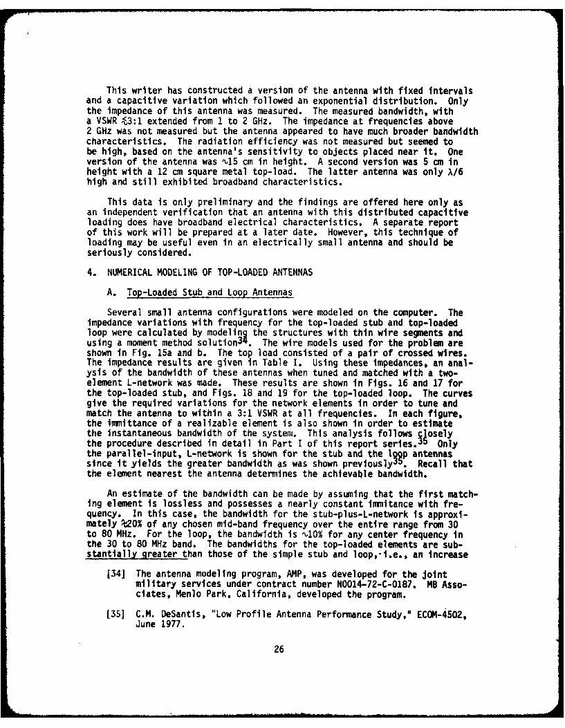
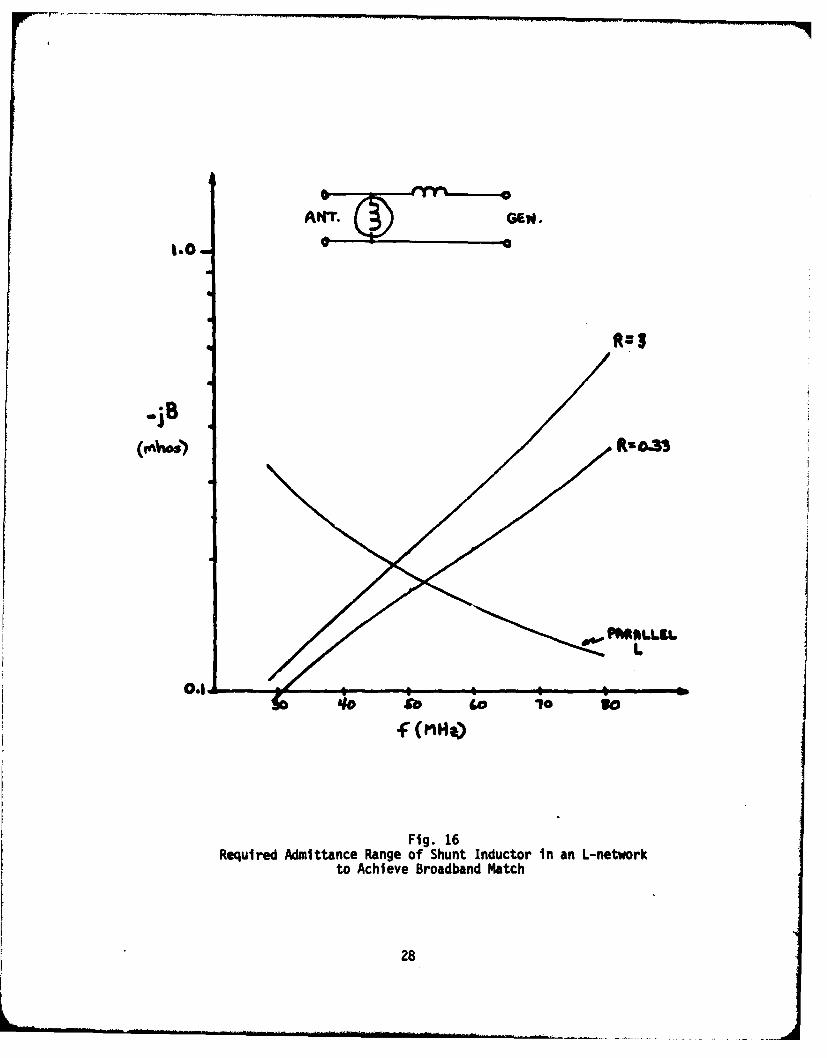
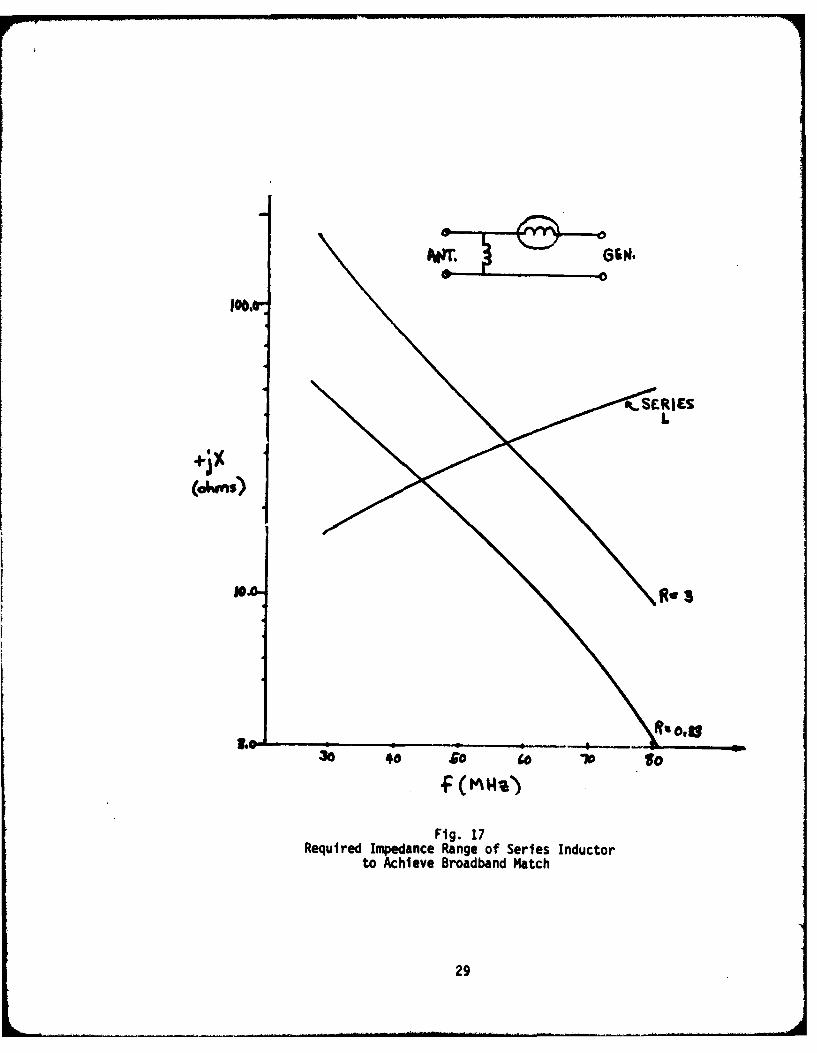
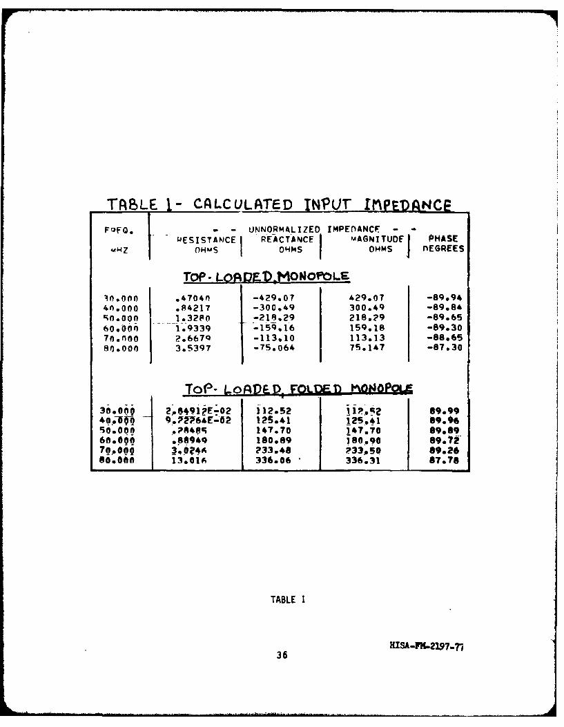
Several small antenna configurations were modeled on the computer. Theimpedance variations with frequency for the top-loaded stub and top-loadedloop were calculated by modeling the structures with thin wire segments andusing a moment method solution3 . The wire models used for the problem areshown in Fig. 15a and b. The top load consisted of a pair of crossed wires.The impedance results are given in Table I. Using these impedances, an anal-ysis of the bandwidth of these antennas when tuned and matched with a two-element L-network was made. These results are shown in Figs. 16 and 17 forthe top-loaded stub, and Figs. 18 and 19 for the top-loaded loop. The curvesgive the required variations for the network elements in order to tune andmatch the antenna to within a 3:1 VSWR at all frequencies. In each figure,the immittance of a realizable element is also shown in order to estimatethe instantaneous bandwidth of the system. This analysis follows qjoselythe procedure described in detail in Part I of this report series.~J Onlythe parallel-input, L-network is shown for the stub and the Iqgp antennassince it yields the greater bandwidth as was shown previously JO. Recall thatthe element nearest the antenna determines the achievable bandwidth.
An estimate of the bandwidth can be made by assuming that the first match-ing element is lossless and possesses a nearly constant immitance with fre-quency. In this case, the bandwidth for the stub-plus-L-network is approxi-mately 2O% of any chosen mid-band frequency over the entire range from 30to 80 MHz. For the loop, the bandwidth is ,10% for any center frequency inthe 30 to 80 MHz band. The bandwidths for the top-loaded elements are sub-stantially greater than those of the simple stub and loop,-i.e., an increase
[34] The antenna modeling program, AMP, was developed for the Jointmilitary services under contract number N0014-72-C-0187. MB Asso-ciates, Menlo Park, California, developed the program.
[35] C.M. DeSantis, "Low Profile Antenna Performance Study," ECOM-4502,June 1977.
26
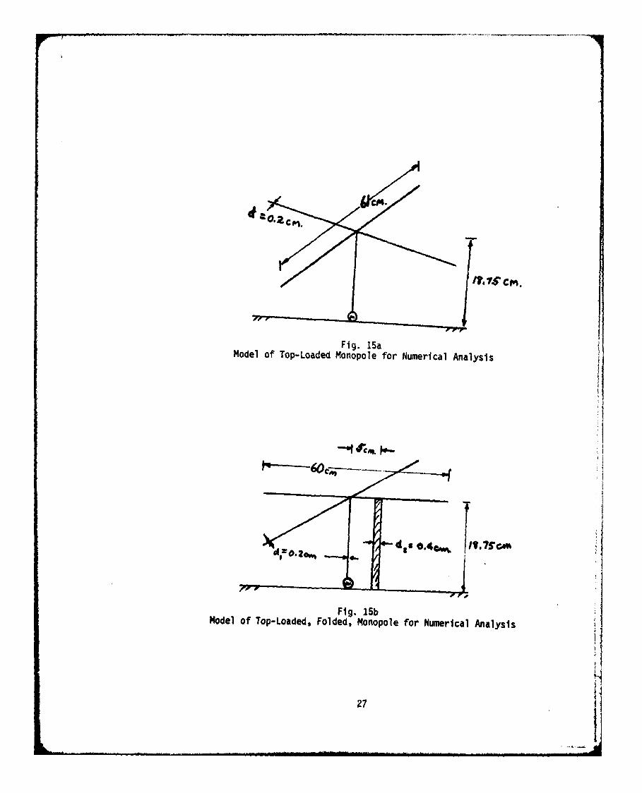
Fig. 15aModel of Top-Loaded Monopole for Numerical Analysis
d. O4@. It.?CV' IwFig. 15b
Model of Top-Loaded, Folded, Monopole for Numerical Analysis
27 i
t(Fig GEN
1.01 Atr.
fa 40 0b t 70 to
(Mma)
Fig. 16Required Admittance Range of Shunt Inductor in an L-network
to Achieve Broadband Match
28
L
Fig. 17Required Impedance Range of Series inductor
to Achieve Broadband Match
29
'II. GEN.
C, C
0.0!-3o '10b 4 70 7
Fig. 18Required Admittance Range of Shunt
Capacitor for Broadband Match
30
too
(ohm)
R-3
10-
30 io to
Fig. 19Required Impedance Range of Series Capacitor
for Broadband Match
31
of ,,2:1% for top-loaded stub, and an increase 4:1% for the top-loaded loop!Recall that these bandwidth figures represent what is achievable with ideal,lossless networks with realizable immittances. Any losses in the system willcause an increase in the bandwidth.
There is one final note about the top-loaded loop. For a fixed heightand top-load area, the ratio of the diameters of the vertical elements canbe changed to effect the shape of the curve shown in Fig. 18 at the lowerfrequencies. It appears that the curves R=3, R=.33 can be made to approacha zero slope at the low end of the band. As an example, consider the parallelelement variation shown in Fig. 20 for a folded, top-loaded structure witha 4:1 diameter ratio of its vertical elements. A comparison with Fig. 18shows a definite flattening of the required element variations for matching,thereby increasing the achievable bandwidth. It is not clear how far thiseffect can be carried, but a more thorough examination will be made as partof the general study of small antennas.
B. Parasite-Loaded Dipole
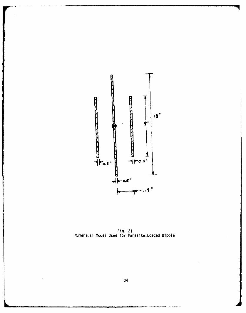
As a final numerical example, consider the parasite-loaded dipole antenna(see Ref. 2), shown in Fig. 21. A pair of parasite elements is placed nextto the antenna; this configuration with the dimensions given was modeled onthe computer and the calculated input impedance is plotted in Fig. 22. Ascan be seen, the antenna has a n2:1 impedance bandwidth without externalmatching in the frequency range from 275 MHz to ,u575 MHz, and from the vari-ation of the impedance, it should be possible to extend the range with a sim-ple external matching circuit. This antenna is not small by any measure.A VHF version would require a 15' long, 5" diameter driven element with para-sites spaced 18" away. However, parasite-loading does produce broadband oper-ation and, perhaps, in combination with one or several of the techniques des-cribed in this report, will lead ultimately to a small, broadband antenna.In this regard, the reader will recall the Goubau antenna which is a combina-tion of driven and undriven elements in a "small" package.
5. CONCLUSION
We have discussed six general types of broadband antennas which haveappeared in the literature. Several experimental antennas have been reportedwhich possess large bandwidths. However, these may be classed into two broadcategories: (a) antennas with bandwidths >50% of an octave; and (b) antennaswith bandwidths <50% but >10% of an octave. The truly small or low-profileantennas have fallen, in general, into the second category while the octaveand multi-octave bandwidth achievements have occurred in X/4- and X/2- dimen-sion antennas. There were several octave-band antenna designs, such as theGoubau antenna and a top-loaded version of the Hallen' antenna, which werelow-profile, but large in cross-section. However, there does not seem tobe a truly small antenna design which possesses large bandwidth. The Goubauantenna comes closest; it is an unusual design which has not appeared before;and yet, in reviewing the literature, the basic ideas for such an antennaseem to have been disclosed. If one had been clever enough, perhaps an antennaof the Goubau type could have been deduced from a combination of several tech-niques which have been reviewed in this report. One wonders how many othernovel designs can be assembled out of that body of literature by "clever"deduction.
32
It seems clear that a broadband design must involve multi-element, folded,
loaded, radiating structures if the antenna is going to be small, at leastin one dimension. Perhaps a combination of the Hallen' technique with oneor several of the other techniques will produce the reflection-free guiding-to-radiating structure discussed by Alford. It is hoped that the collectionof ideas gathered into this report series will lead to new knowledge. PartIII of the series provides a bibliography of published articles on small an-tennas and broadband antenna techniques.
0 .4. 0 "
,.PARALLELC1.jB
0.3
0.19
0.1530 40 42 60 10 o
Fig. 20Admittance Variation of Capacitor Required to Match a Folded Antenna Having
a 4:1 Diameter Ratio in its Vertical Element
33
-1 "1 IAfd1"s
0.5|!
Fig. 21Numerical Model Used for Parasite-Loaded Dipole
34
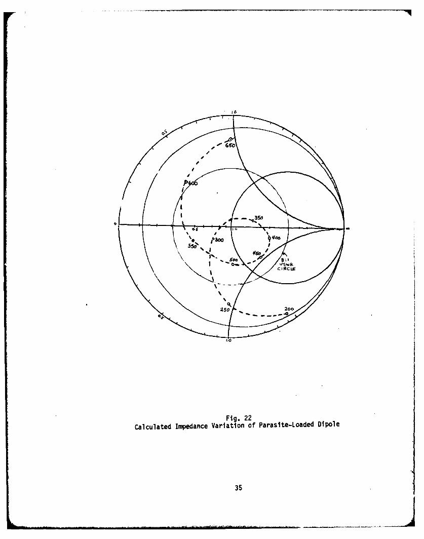
Fig. 22Calculated Impedance Variation of Parasite-Loaded Dipole
35
T I BLE 1- CALCULATED INPUT IMPEDANCE
FoFG. - UNNORMALIZED IMPEDANCF - -
" PESISTANCE REACTANCE MAGNITUDE PHASEeuOHMS OHMS OHMS nEGREES
TOP - LOl DED.tDMONOPOLE
3f.Ofo .4704n -429.07 429.07 -89o94
4n.000 .84217 -300o49 300.49 -89.84
0,6000 1.32P0 -218,29 218.?9 -89.6560,000f * 1.9339 -159.16 159,18 -89.3070o00 2,6670 -113,10 113.13 -88.6580,000 3.5397 -75,064 75.147 -87.30
ToP- L ojDF- rO nE rKONOPoLE30.009 2'1)491?IE'2 I .12*S2 ip 89.99
4o -0- 9.72764E-02 12r.41 12S.41 S9.4650000 ,?848c 147.70 147,70 89.8960.090 .88949 180.89 160.90 89.727,009 3qO 4A 233.48 P33,50 89.26
60.0000 13.016 336.06 336.31 67.78
TABLE I
HISA-K.2197.-36