Embed Size (px)
Citation preview

Economic and field evaluation of modular
cabling techniques in the Belgacom network

1. Introduction
Belgacom’s future network structure
2. Modular cabling systems - Technical evaluation
- introduction
- product description
- competing technologies
- network concept
3. Modular cabling systems - Economical evaluation
- investment analysis
- present value approach
- inv / npv results

1. Introduction
Belgacom’s future network structure

NBservices
I-TMN
IN Server
SDH
SAP SAPLC/LDC
SAP
SDH
DP
A/HDSL
PON
WLL
Clients
SL
SW
TR
SAP
AN
CPECOAX
TV DP DP
(Network Interworking)
DP
TV
ATM
PON
4
BELGACOM’s NETWORKARCHITECTURES EVOLUTIONBELGACOM’s NETWORKARCHITECTURES EVOLUTIONBELGACOM’s NETWORKARCHITECTURES EVOLUTIONBELGACOM’s NETWORKARCHITECTURES EVOLUTION

BELGACOM’s NETWORKARCHITECTURES EVOLUTIONBELGACOM’s NETWORKARCHITECTURES EVOLUTIONBELGACOM’s NETWORKARCHITECTURES EVOLUTIONBELGACOM’s NETWORKARCHITECTURES EVOLUTION
Clients
ON
ON
ONSDHLocalClients SDH
Local
ON
ON
ON
ClientsSDH
Client
OVERVIEW FSANOVERVIEW FSAN
SDHBACKBONE
O & M
ON
ONPFS
Switch
Management System SDH
Node SDH
Optical Node
FH
PFS Pulling Fibre System
Wireless In The Loop
O & M
FH - SDH
SWI V5
PFS
ON
LC
LC
LC
LC
LC
LC
ZC
Clients
PFS
GATEWAYS

BELGACOM’s NETWORKARCHITECTURES EVOLUTIONBELGACOM’s NETWORKARCHITECTURES EVOLUTIONBELGACOM’s NETWORKARCHITECTURES EVOLUTIONBELGACOM’s NETWORKARCHITECTURES EVOLUTION
ARCHITECTURE ON RINGARCHITECTURE ON RING
ADM4 ADM4
O
M
D
F
Backbone
Backbone
36F
36F
ADM4
OMDF
ADM4
OMDF
ADM4
OMDF 4v - 1T8v- 2T8v- 2T8v- 2TReserve 1T
Ring 36 F.O.
ON XXX
ON XXZ
ON XXY

BELGACOM’s NETWORKARCHITECTURES EVOLUTIONBELGACOM’s NETWORKARCHITECTURES EVOLUTIONBELGACOM’s NETWORKARCHITECTURES EVOLUTIONBELGACOM’s NETWORKARCHITECTURES EVOLUTION
ARCHITECTURE DISTRIBUTION RINGARCHITECTURE DISTRIBUTION RING
ADM4
ADM1
2MB - G703 -PRA
ADM1
ATM
client
R-MUX
LLSYRAR ADMØ
POTS ISDN
client
ADM1
POTSISDN
ADMØ
client
client
4 F - T 9 4 F - T 9
4 F - T 9 4 F - T 8
4 F - T 8
ON
4 F - T 7 4 F - T 6 4 F - T 1
4 F - T 1 4 F - T 6 4 F - T 7
Boucle 36 F.O.

BELGACOM’s NETWORKARCHITECTURES EVOLUTIONBELGACOM’s NETWORKARCHITECTURES EVOLUTIONBELGACOM’s NETWORKARCHITECTURES EVOLUTIONBELGACOM’s NETWORKARCHITECTURES EVOLUTION
DISTRIBUTION F.O. : OSPDISTRIBUTION F.O. : OSP
1 Splice hole per 2 clients
O N
DISTRIBUTION RINGTELEZONE
= Splice hole
X Client
2 ducts

BELGACOM’s NETWORKARCHITECTURES EVOLUTIONBELGACOM’s NETWORKARCHITECTURES EVOLUTIONBELGACOM’s NETWORKARCHITECTURES EVOLUTIONBELGACOM’s NETWORKARCHITECTURES EVOLUTION
DISTRIBUTION F.O. : ALTERNATIVEDISTRIBUTION F.O. : ALTERNATIVE
Pulling Fibre System (PFS)
MICROLIGHT - S.A. VULCANMAINETTIE : ductsRAYCHEM : splices, ...OPTICAL FIBRE : fibres
Pilot projects in 1996
Fine tuning of the system : 02/97
Commercial projects : 1Q98
Volume Deployment : 3Q98
! DUCTS * no more splice holes* cheaper splicing technology = copper* installation of the fibres when there is a new customer ==> ROI

2. Modular Cabling Systems
Technical Evaluation

Modular cabling systemsTechnical evaluation
• product description
• manufacturers
• competing technologies
• network concept
• field trial(s)

Modular cabling systemsproduct description
• multi- tube system : 2/4/7/19-way• direct buried version
• direct installed version
• multi-fibre units : 2/4/8 fibre units• installation techniques :
• blown fibre technique
• pulled fibre technique
• mechanical building blocks :• tube branchout and connecting joints
• repair kit
• customer lead in box

Competing technologies• “traditional” fibre optic cabling technology :
– 4 or 8 fibres per tube
– FIST technology for customer independence
– usage of concrete manholes for splicing and/or recoiling ; no direct buried splices
• “inline” fibre optic cabling technology :– idem + direct buried customer connection splice
• “modular cabling” technology– 2,4 or 8 fibre unit per tube
– only one splice at Optical Node
– whole system is direct buried
– handling of the system : similar as copper outside plant

Modular system Network ConceptAdvantages of a modular fibre system :
• low up front investment• modular, adaptable upon demand from outside to inside• rapid fibre deployment• no overkill investments• point to point fibre reduces # of splices• installation of fibre bundles on demand
Disadvantages of a modular fibre system :• installation of individual fibre bundles more time consuming• more complex repair

Modular system Network view
customer customer
traditional FO Cable Modular distribution system
Optical NodeLocal Center
–ideally suited as distribution and drop system for direct connection of customers

Modular system Network view
traditional FO Cable Modular cabling technique
Optical NodeLocal Center
KVD1
KVD4
KVD2
KVD5
KVD3
–optional for FTT/C-KVD (from ON to KVD) in a non-full deployment strategy

Modular system Network Concepttowards implementation
– simplicity of the system assures the retrainability of “copper people” due to similarity in handling with the existing copper technology

FTT BUILDING - PILOT PROJECT IN NIEUWPOORT

FTT FTT BUILDING BUILDING PILOT PILOT PROJECT IN NIEUWPOORTPROJECT IN NIEUWPOORT
Introduction : - connect new buildings in F.O.- connect existing buildings in F.O.
Desaturates KVD’s so that growth of uni-familial
houses and small buildings can be handled by existing KVD’s/cu-network.
Introduction of the site :
• Fundamental plan of the network Nieuwpoort
• Topographical plan of the site

FTTB / FTTFTTB / FTTKVDKVD - NIEUWPOORT - NIEUWPOORT
a : b MDF
ADM ADM0
OMDF
O & M
LC
ADM
BUILDING n
ADM
ADM0
POTS ISDN
CUKVD
+ HDSL
ADM
ADM0
ADM
ADM0
POTS ISDNPOTS ISDN
2MB 2MB
BUILDING 1 BUILDING 2
first road
second road
O.N.
HDSL2MB
ON - CABINET
PROVISIONING CUSTOMER SERVICE
a : b
TEST

Cabling of the local junctionCabling of the local junction
ON 091LDC HOME
LCNIEUWPOORT
O.N. 097
12345
12345678910
Tube 1 : LDC 091 (HOME)Tube 2 : LDC 091 (HOME)Tube 3 : O.N. 097Tube 4 : O.N. 097Tube 5 : SDH loop
Tube 6-10 : (PDH O.N. 097)
20 fibres
40 fibres
20 fibres

CCable plan of O.N. able plan of O.N. (on cable level) (on cable level)
FIST 1 FIST 2
O.N.cabinet
16 fibres
FIST 0
80 fibres
16 fibres
16 fibres
16 fibres
16 fibres
16 fibres
16 fibres
16 fibres
16 fibres
16 fibres
16 fibres
16 fibres
16 fibres
16 fibres
16 fibres
16 fibres
16 fibres
16 fibres
16 fibres
16 fibres
80 fibres
24 fibres
8 fibres 8 fibres
cable 1 : 40 fibres cable 2 : 40 fibres cable 3 : 40 fibres cable 4 : 40 fibres
20 fibres 40 fibres
4011 4012 4013 4014 4015 4021 4022 4023 4024 4025 4031 4032 4033 4034 4035 4041 4042 4043 4044 40454036
LC
LDC 091

CCable plan of O.N. able plan of O.N. (on tube-level) (on tube-level)
FIST 1 FIST 2
O.N.cabinet
FIST 0
ADM
ADM ADM ADM ADM ADM ADMADM ADM ADM ADM ADM ADM ADM ADM ADM ADM ADM ADM ADM ADMADM
4011 4012 4013 4014 4015 4021 4022 4023 4024 4025 4031 4032 4033 4034 4035 4041 4042 4043 4044 40454036
3456
2
789
10
1
345
21
3456
21
:910
34
21
:9
10
34
21
:9
10
34
21
:9
10
34
21
:

CCabling plan distributionabling plan distribution‘fibres per building/KVD’‘fibres per building/KVD’
O
N
tube(s)
1 - 4
5 - 8
37-38
39-40
16 fibres input 16 fibres
33-34 33-34 33-34
35-36 35-36 35-36
ADM1 ADM1ADM1
BUILDING 1 BUILDING 2 BUILDING n
16 f.

3. Modular Cabling System
Economical Evaluation
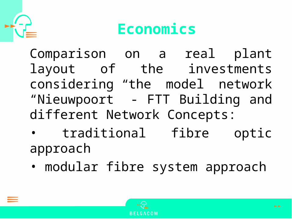
Economics
Comparison on a real plant layout of the investments considering the model network “Nieuwpoort” - FTT Building and different Network Concepts:
• traditional fibre optic approach
• modular fibre system approach

Investment analysis
0
1000000
2000000
3000000
4000000
5000000
6000000
Duct Chamber Cable SpliceBox Measurement TermWork
Classic Modular
Total investment

Present Value (15%)PV Cumulative
1500000
2000000
2500000
3000000
3500000
4000000
4500000
Year1 Year2 Year3 Year4 Year5
Classic
PFS
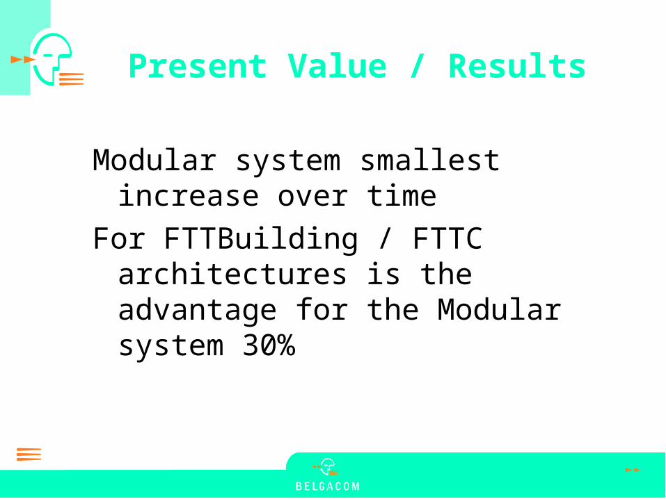
Present Value / Results
Modular system smallest increase over time
For FTTBuilding / FTTC architectures is the advantage for the Modular system 30%