Embed Size (px)
Citation preview
ECE R.13 Page 1
Informal document No. GRRF-56-2 (56th GRRF, 20-22 September 2004, agenda item 1.1.)
ECONOMIC COMMISSION FOR EUROPE INLAND TRANSPORT COMMITTEE World Forum for Harmonization of Vehicle Regulations (WP.29) Working Party on Brakes and Running Gear (GRRF) Fifty-sixth session, 20-22 September 2004,
PROPOSAL FOR DRAFT AMENDMENTS TO REGULATION No. 13
(Braking)
Transmitted by the expert from the United Kingdom
Note: The text reproduced below has been prepared by the expert from the United Kingdom and proposes amendments to the paragraphs in the body of Regulation 13 that need to be amended in order to delete category M1 vehicles.
__________________________ _______________ Note: This document is distributed to the Experts on Brakes and Running Gear only.
ECE R.13 Regulation
Page 2
UNITED NATIONS AGREEMENT CONCERNING THE ADOPTION OF UNIFORM CONDITIONS OF APPROVAL AND RECIPROCAL RECOGNITION OF APPROVAL FOR MOTOR VEHICLE
EQUIPMENT AND PARTS done at Geneva on 20 March 1958 _____________ Addendum 12: Regulation No. 13 Revision 4 Incorporating:
01 series of amendments - Date of entry into force: 29 August 1973 02 series of amendments - Date of entry into force: 11 July 1974 03 series of amendments - Date of entry into force: 4 January 1979 04 series of amendments - Date of entry into force: 11 August 1981 05 series of amendments - Date of entry into force: 26 November 1984 Supplement 1 to the 05 series of amendments: Date of entry into force: 1 April 1987 Supplement 2 to the 05 series of amendments: Date of entry into force: 5 October 1987 Supplement 3 to the 05 series of amendments: Date of entry into force: 29 July 1988 06 series of amendments - Date of entry into force: 22 November 1990 Supplement 1 to the 06 series of amendments: Date of entry into force:15 November 1992 Supplement 2 to the 06 series of amendments: Date of entry into force: 24 August 1993 07 series of amendments - Date of entry into force: 18 September 1994 08 series of amendments - Date of entry into force: 26 March 1995 09 series of amendments - Date of entry into force: 1 October 1996 Supplement 1 to the 09 series of amendments: Date of entry into force: 15 January 1997 Supplement 2 to the 09 series of amendments: Date of entry into force: 22 January 1997 Supplement 3 to the 09 series of amendments: Date of entry into force: 22 April 1998 Supplement 4 to the 09 series of amendments: Date of entry into force: Feb 1999 Supplement 5 to the 09 series of amendments: Date of entry into force: 27 Dec 2000 Supplement 6 to the 09 series of amendments: Date of entry into force: 27 Feb 2002 Supplement 7 to the 09 series of amendments: Date of entry into force: 31 Jan 2003 Supplement 8 to the 09 series of amendments: Date of entry into force: 26 Feb 2004
UNIFORM PROVISIONS CONCERNING THE APPROVAL OF VEHICLES OF CATEGORIES M, N AND O WITH REGARD TO BRAKING __________________
ECE R.13 Page 3
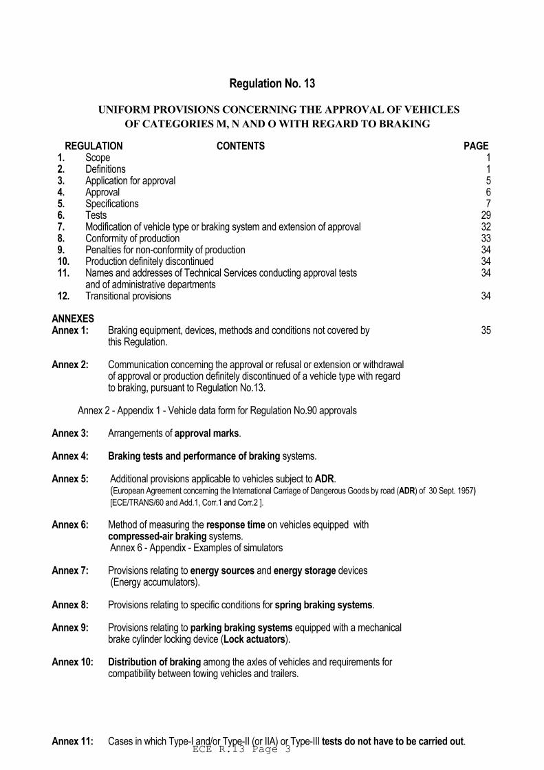
Regulation No. 13 UNIFORM PROVISIONS CONCERNING THE APPROVAL OF VEHICLES OF CATEGORIES M, N AND O WITH REGARD TO BRAKING REGULATION CONTENTS PAGE 1. Scope 1 2. Definitions 1 3. Application for approval 5 4. Approval 6 5. Specifications 7 6. Tests 29 7. Modification of vehicle type or braking system and extension of approval 32 8. Conformity of production 33 9. Penalties for non-conformity of production 34 10. Production definitely discontinued 34 11. Names and addresses of Technical Services conducting approval tests 34 and of administrative departments 12. Transitional provisions 34 ANNEXES Annex 1: Braking equipment, devices, methods and conditions not covered by 35 this Regulation. Annex 2: Communication concerning the approval or refusal or extension or withdrawal of approval or production definitely discontinued of a vehicle type with regard to braking, pursuant to Regulation No.13. Annex 2 - Appendix 1 - Vehicle data form for Regulation No.90 approvals Annex 3: Arrangements of approval marks. Annex 4: Braking tests and performance of braking systems. Annex 5: Additional provisions applicable to vehicles subject to ADR. (European Agreement concerning the International Carriage of Dangerous Goods by road (ADR) of 30 Sept. 1957)
[ECE/TRANS/60 and Add.1, Corr.1 and Corr.2 ]. Annex 6: Method of measuring the response time on vehicles equipped with compressed-air braking systems. Annex 6 - Appendix - Examples of simulators Annex 7: Provisions relating to energy sources and energy storage devices (Energy accumulators). Annex 8: Provisions relating to specific conditions for spring braking systems. Annex 9: Provisions relating to parking braking systems equipped with a mechanical brake cylinder locking device (Lock actuators). Annex 10: Distribution of braking among the axles of vehicles and requirements for compatibility between towing vehicles and trailers. Annex 11: Cases in which Type-I and/or Type-II (or IIA) or Type-III tests do not have to be carried out.
ECE R.13 Regulation
Page 4
Annex 11 - Appendix 1 - Tables I, II and III Annex 11 - Appendix 2 - Alternative procedures for Type-I and Type-III tests for trailer brakes Annex 11 - Appendix 3 - Model test report form (see 3.7.1/2 of Appendix 2 to this Annex) Annex 11 – Appendix 4 – Model test report form for an alternative Brake Adjustment Device. (see 3.7.3. of Appendix 2 to this Annex.) Annex 12: Conditions governing the testing of vehicles equipped with inertia (overrun) braking systems. Annex 12 - Appendix 1 - Figures 1-8 Annex 12 - Appendix 2 - Test report on inertia-braking system control device Annex 12 - Appendix 3 - Brake test report Annex 12 - Appendix 4 - Test report on the compatibility of the inertia brake control device, the transmission and the brakes on the trailer Annex 13: Test requirements for vehicles fitted with anti-lock systems. Annex 13 - Appendix 1 - Symbols and definitions Annex 13 - Appendix 2 - Utilization of adhesion Annex 13 - Appendix 3 - Performance on differing adhesion surfaces Annex 13 - Appendix 4 - Method of selection of the low-adhesion surfaces Annex 14: Test conditions for trailers with electrical braking systems. Annex 14 - Appendix - Compatibility of the braking rate of the trailer and MFDD of the combination. Annex 15: Inertia dynamometer test method for brake linings. Annex 16 Now blank - Reserved. Annex 17 Test procedure to assess functional compatibility of vehicles with an electric control line. Annex 18 Special requirements to be applied to the: Safety Aspects of Complex Electronic vehicle control systems. Annex 19 Performance Testing of Braking Components. Annex 20 Alternative procedure for the Type Approval of Trailers. Codes for countries ratifying the Agreement ( Referenced on Page 6 footnote 3/ ) 1 for Germany, 2 France, 3 Italy, 4 Netherlands, 5 Sweden, 6 Belgium, 7 Hungary, 8 Czech Republic, 9 Spain, 10 Yugoslavia, 11 United
Kingdom, 12 Austria, 13 Luxembourg, 14 Switzerland, 16 Norway, 17 Finland, 18 Denmark, 19 Romania, 20 Poland, 21 Portugal, 22 Russian Federation, 23 Greece, 24 Ireland, 25 Croatia, 26 Slovenia, 27 Slovakia, 28 Belarus, 29 Estonia, 31 Bosnia Herzegovina, 32 Latvia, 34 Bulgaria, 37 Turkey, 40 former Yugoslav Rep. of Macedonia, 42 EC, 43 Japan, 45 Australia, 46 Ukraine, 47 South Africa, 48 New Zealand. Vacant numbers: 15, 30, 32, 33, 35, 36, 38, 39, 41, 44 and 49 onwards. - Subsequent numbers shall be assigned to other countries in the chronological order in which they ratify the Agreement Concerning the Adoption of Uniform Conditions of Approval and Reciprocal Recognition of Approval for Motor Vehicle Equipment and Parts, or in which they accede to that Agreement, and the numbers thus assigned shall be communicated by the Secretary-General of the United Nations to the Contracting Parties to the Agreement.
Regulation No. 13 UNIFORM PROVISIONS CONCERNING THE APPROVAL OF VEHICLES OF CATEGORIES M, N AND O WITH REGARD TO BRAKING 1. SCOPE.
Regulation ECE-R-13
ECE-R-13 Page - 5
1.1. This Regulation applies to the braking of power-driven vehicles individually and of trailers individually of
categories M2, M3, N and O as defined in Annex 7 to the Consolidated Resolution on the Construction of Vehicles (R.E. 3). */
1.2. This Regulation does not cover : 1.2.1. vehicles with a design speed not exceeding 25 km/h; 1.2.2. trailers which may not be coupled to power-driven vehicles with a design speed exceeding 25 km/h; 1.2.3. vehicles fitted for invalid drivers; 1.3. Subject to the applicable provisions of this Regulation, the equipment, devices, methods and
conditions enumerated in Annex 1 are not covered by this Regulation. 2. DEFINITIONS. For the purposes of this Regulation , 2.1. "Approval of a vehicle" means the approval of a vehicle type with regard to braking; 2.2. "Vehicle type" means a category of vehicles which do not differ in such essential respects as : 2.2.1. in the case of power-driven vehicles, 2.2.1.1. the vehicle category, (see paragraph 1.1. above); 2.2.1.2. the maximum mass, as defined in paragraph 2.16. below; 2.2.1.3. the distribution of mass among the axles; 2.2.1.4. the maximum design speed; 2.2.1.5. a different type of braking equipment, with more particular reference to the presence or
otherwise of equipment for braking a trailer, or any presence of an electric regenerative braking system;
2.2.1.6. the number and arrangement of the axles; 2.2.1.7. the engine type; 2.2.1.8. the number and ratios of gears; 2.2.1.9. the final drive ratios; 2.2.1.10. the tyre dimensions; _______
* / Braking requirements for M1 category vehicles are now to be found in the Regulation No. 13-H. 2.2.2. in the case of trailers, 2.2.2.1. the vehicle category (see paragraph 1.1. above); 2.2.2.2. the maximum mass, as defined in paragraph 2.16. below; 2.2.2.3. the distribution of mass among the axles; 2.2.2.4. a different type of braking equipment; 2.2.2.5. the number and arrangement of the axles; 2.2.2.6 the tyre dimensions;
2.3. "Braking system" means the combination of parts whose function is progressively to reduce the speed of
ECE-R-13 Regulation.
ECE-R-13 Page - 6
a moving vehicle or bring it to a halt, or to keep it stationary if it is already halted; these functions are specified in paragraph 5.1.2. of this Regulation. The equipment consists of the control, the transmission, and the brake proper;
2.4. "Control" means the part actuated directly by the driver (or in the case of some trailers, by an assistant) to
furnish to the transmission the energy required for braking or controlling it. This energy may be the muscular energy of the driver, or energy from another source controlled by the driver, or in appropriate cases the kinetic energy of a trailer, or a combination of these various kinds of energy;
2.4.1. "Actuation" means both application and release of the control; 2.5. "Transmission" means the combination of components comprised between the control and the brake and
linking them functionally. The transmission may be mechanical, hydraulic, pneumatic, electric or mixed. Where the braking power is derived from or assisted by a source of energy independent of the driver, the reserve of energy in the system is likewise part of the transmission.
The transmission is divided into two independent functions: the control transmission and the energy
transmission. Whenever the term "transmission" is used alone in this Regulation, it means both the "control transmission" and the "energy transmission". The control and supply lines between towing vehicles and trailers shall not be considered as parts of the transmission:
2.5.1. "Control transmission" means the combination of the components of the transmission which control the
operation of the brakes, including the control function and the necessary reserve(s) of energy; 2.5.2. "Energy transmission" means the combination of components which supply to the brakes, the energy
necessary for their function, including the reserve(s) of energy necessary for the operation of the brakes; 2.6. "Brake" means the part in which the forces opposing the movement of the vehicle develop. It may be a
friction brake (when the forces are generated by friction between two parts of the vehicle moving relatively to one another); an electrical brake (when the forces are generated by electro-magnetic action between two parts of the vehicle moving relatively to but not in contact with one another); a fluid brake (when the forces are generated by the action of a fluid situated between two parts of the vehicle moving relatively to one another); or an engine brake (when the forces are derived from an artificial increase in the braking action, transmitted to the wheels, of the engine);
2.7. "Different types of braking systems" means systems which differs in such essential respects as: 2.7.1. components having different characteristics; 2.7.2. a component made of materials having different characteristics, or a component differing in shape or size;
2.7.3. a different assembly of the components; 2.8. "Component of a braking system" means one of the individual parts which, when assembled, constitute
the braking system; 2.9. "Continuous braking" means the braking of a combination of vehicles through an installation having the
following characteristics: 2.9.1. a single control which the driver actuates progressively, by a single movement, from his driving seat; 2.9.2. the energy used for braking the vehicles constituting the combination, is furnished by the same source
(which may be the muscular energy of the driver); 2.9.3. the braking installation ensures simultaneous or suitably-phased braking of each of the constituent
vehicles of the combination, whatever their relative positions; 2.10. "Semi-continuous braking" means the braking of a combination of vehicles through an installation
having the following characteristics:
Regulation ECE-R-13
ECE-R-13 Page - 7
2.10.1. a single control which the driver actuates progressively, by a single movement, from his driving seat; 2.10.2. the energy used for braking the vehicles constituting the combination is furnished by two different
sources (one of which may be the muscular energy of the driver); 2.10.3. the braking installation ensures simultaneous or suitably-phased braking of each of the constituent
vehicles of the combination, whatever their relative positions; 2.11. "Automatic braking" means braking of the trailer or trailers occurring automatically in the event of
separation of components of the combination of coupled vehicles, including such separation through the breakage of a coupling, the effectiveness of the braking of the remainder of the combination not being thereby destroyed;
2.12. "Inertia (or overrun) braking" means braking by utilizing the forces generated by the trailer's moving
up on the towing vehicle; 2.13. "Progressive and graduated braking" means braking during which, within the normal operating
range of the equipment, and during actuation of the brakes (see paragraph 2.21. below): 2.13.1. the driver can at any moment increase or decrease the braking force by acting on the control; 2.13.2. the braking force varies proportionally as the action on the control (monotonic function); and 2.13.3. the braking force can be easily regulated with sufficient precision; 2.14. “Phased Braking” is a means which may be used where two or more sources of braking are
operated from a common control, whereby one source may be given priority by phasing back the other source(s) so as to make increased control movement necessary before they begin to be brought into operation
2.15. "Endurance Braking System" 1/ (Retarder) means an additional braking system having the
capability to provide and maintain a braking effect over a long period of time without a significant reduction in performance. The term "Endurance Braking System" covers the complete system including the control device,
2.15.1. The endurance braking system may comprise a single device or a combination of several devices.
Each device may have its own control. ______________________ 1/ Until uniform procedures have been agreed to calculate the effects of endurance braking systems on the provisions in
Annex 10 to this Regulation, this definition does not cover vehicles fitted with regenerative braking systems. 2.15.2. Control configurations for endurance braking systems: 2.15.2.1. "Independent endurance braking system" means a endurance braking system whose control
device is separated from that of the service and other braking systems, 2.15.2.2. "Integrated endurance braking system" 2/ means a endurance braking system whose control device
is integrated with that of the service braking system in such a way that both endurance braking system and service braking systems are applied simultaneously or suitably phased by operation of the combined control device,
2.15.2.3. "Combined endurance braking system" means an integrated endurance braking system, which in
ECE-R-13 Regulation.
ECE-R-13 Page - 8
addition has a cut-out device, which allows the combined control to apply the service braking system alone;
2.16. "Laden vehicle" means, except where otherwise stated, a vehicle so laden as to attain its "maximum mass"; 2.17. "Maximum mass" means the maximum mass stated by the vehicle manufacturer to be technically
permissible (this mass may be higher than the "permissible maximum mass" laid down by the national administration);
2.18. "The distribution of mass among the axles" means the distribution of the effect of the gravity on the
mass of the vehicle and/or its contents among the axles; 2.19. "Wheel / axle load" means the vertical static reaction (force) of the road surface in the contact area on the
wheel(s) of the axle; 2.20. "Maximum stationary wheel / axle load" means the stationary wheel / axle load achieved under the
condition of the laden vehicle; 2.21. "Electric regenerative braking system" means a braking system which, during deceleration, provides
for the conversion of vehicle kinetic energy into electric energy ; 2.21.1. "Electric regenerative braking control" means a device which modulates the action of the electric
regenerative braking system; 2.21.2. "Electric regenerative braking system of category A" means an electric regenerative braking
system which is not part of the service braking system; 2.21.3. "Electric regenerative braking system of category B" means an electric regenerative braking
system which is part of the service braking system; 2.21.4. "Electric State of Charge" means the instantaneous ratio of electric quantity of energy stored in the
traction battery relative to the maximum quantity of electric energy which could be stored in this battery;
2.21.5. "Traction battery" means an assembly of accumulators constituting the storage of energy used for
powering the traction motor(s) of the vehicle; _____________________ 2/ Until uniform procedures have been agreed to calculate the effects of endurance braking systems on the provisions in
Annex 10 to this Regulation, vehicles equipped with an integrated endurance braking system must also be equipped with an anti-lock system acting at least on the service brakes of the endurance braking system controlled axle and on the endurance braking system itself, and tested according to the provisions of Annex 13 to this Regulation.
2.22. "Hydraulic braking system with stored energy" means a braking system where energy is supplied by
a hydraulic fluid under pressure, stored in one or more accumulators, fed from one or more pressure pumps each fitted with a means of limiting the pressure to a maximum value. This value shall be specified by the manufacturer.
2.23. "Simultaneous lockup of the front and rear wheels" refers to the condition when the time interval
between the first occurrence of lockup of the last (second) wheel on the rear axle and the first occurrence of lockup on the last (second) wheel on the front axle is less than 0.1 second.
2.24. "Electric control line" means the electrical connection between power-driven vehicle and trailer which
provides the braking control function to the trailer. It comprises the electrical wiring and connector and includes the parts for data communication and the electrical energy supply for the trailer control transmission;
Regulation ECE-R-13
ECE-R-13 Page - 9
2.25. "Data communication" means the transfer of digital data under the rules of a protocol; 2.26. "Point-to-point" means a topology of a communication network with only two units. Each unit has an
integrated termination resistor for the communication line; 2.27. "Coupling force control" means a system/function to balance automatically the braking rate of towing
vehicle and trailer; 2.28. "Nominal value" definitions for braking reference performance are required to put a value on the
transfer function of the braking system, relating output to input for vehicles individually and when used in combination:
2.28.1. "Nominal value" is defined, for a power-driven vehicle, as the characteristic which can be
demonstrated at Type Approval and which relates the braking rate of the vehicle on its own, to the level of the braking input variable;
2.28.2. "Nominal value" is defined, for a trailer, as the characteristic which can be demonstrated at Type
Approval and which relates the braking rate to the coupling head signal; 2.28.3. "Nominal demand value" is defined, for coupling force control, as the characteristic which relates the
coupling head signal to the braking rate and which can be demonstrated at Type Approval, within the limits of the compatibility bands of Annex 10.
2.29. “Automatically Commanded Braking” means a function within a Complex Electronic Control
System where actuation of the braking system(s) or brakes of certain axles is made for the purpose of generating vehicle retardation with or without a direct action of the driver, resulting from the automatic evaluation of on-board initiated information.
2.30. “Selective Braking” means a function within a Complex Electronic Control System where actuation
of individual brakes is made by automatic means in which vehicle retardation is secondary to vehicle behaviour modification
2.31. “Reference braking forces” means the braking forces of one axle generated at the
circumference of the tyre on a roller brake tester, relative to brake actuator pressure and declared at the time of Type Approval.
3. APPLICATION FOR APPROVAL. 3.1. The application for approval of a vehicle type with regard to braking shall be submitted by the vehicle
manufacturer or by his duly accredited representative. 3.2. It shall be accompanied by the under-mentioned documents in triplicate and by the following
particulars:
3.2.1. a description of the vehicle type with regard to the items specified in paragraph 2.2. above. The numbers and/or symbols identifying the vehicle type and, in the case of power-driven vehicles, the engine type shall be specified;
3.2.2. a list of the components, duly identified, constituting the braking system;
3.2.3. a diagram of assembled braking system and an indication of the position of its components on the
vehicle; 3.2.4. detailed drawings of each component to enable it to be easily located and identified. 3.3. A vehicle, representative of the vehicle type to be approved, shall be submitted to the Technical
Service conducting the approval tests.
ECE-R-13 Regulation.
ECE-R-13 Page - 10
3.4. The competent authority shall verify the existence of satisfactory arrangements for ensuring effective
control of the conformity of production before type approval is granted. 4. APPROVAL. 4. 1. If the vehicle type submitted for approval pursuant to this Regulation meets the requirements of
paragraphs 5. and 6. below, approval of that vehicle type shall be granted. 4.2. An approval number shall be assigned to each type approved, its first two digits (at present 09) shall
indicate the series of amendments incorporating the most recent major technical amendments made to the Regulation at the time of issue of the approval. The same Contracting Party shall not assign the same number to the same vehicle type equipped with another type of braking system, or to another vehicle type.
4.3. Notice of approval or of refusal of approval of a vehicle type pursuant to this Regulation shall be
communicated to the Parties to the Agreement applying this Regulation by means of a form conforming to the model in Annex 2 to this Regulation and of a summary of the information contained in the documents referred to in paragraphs 3.2.1. to 3.2.4. above, the drawings supplied by the applicant for approval being in a format not exceeding A4 (210 x 297 mm), or folded to that format, and on an appropriate scale.
4.4. There shall be affixed, conspicuously and in a readily accessible place specified on the approval form,
to every vehicle conforming to a vehicle type approved under this Regulation, an international approval mark consisting of:
4.4.1. a circle surrounding the letter "E" followed by the distinguishing number of the country which has
granted approval, 3/ and of: 4.4.2. the number of this Regulation, followed by the letter "R", a dash and the approval number to the
right of the circle prescribed in paragraph 4.4.1. above. 4.5. However, if a vehicle of category M2 or M3 has been approved pursuant to the provisions of Annex 4
paragraph 1.8. to this Regulation, the number of the Regulation shall be followed by the letter M. 4.6. If the vehicle conforms to a vehicle type approved under one or more other Regulations, annexed to
the Agreement, in the country which has granted approval under this Regulation, the symbol prescribed in paragraph 4.4.1. above need not be repeated; in such a case, the Regulation and approval numbers and the additional symbols of all the Regulations under which approval has been granted in the country which has granted approval under this Regulation shall be placed in vertical columns to the right of the symbol prescribed in paragraph 4.4.1. above.
_____________________ 3/ For number codes of ratifying countries, see the footnote below the List of Contents. 4.7. The approval mark shall be clearly legible and be indelible. 4.8. The approval mark shall be placed close to or on the vehicle data plate. 4.9. Annex 3 to this Regulation gives examples of arrangements of approval marks. 5. SPECIFICATIONS. 5.1. General 5.1.1. Braking system
Regulation ECE-R-13
ECE-R-13 Page - 11
5.1.1.1. The braking system shall be so designed, constructed and fitted as to enable the vehicle in normal use, despite the vibration to which it may be subjected, to comply with the provisions of this Regulation.
5.1.1.2. In particular, the braking system shall be so designed, constructed and fitted as to be able to resist
the corroding and ageing phenomena to which it is exposed. 5.1.1.3. Brake linings shall not contain asbestos. 5.1.1.4. The effectiveness of the braking systems, including the electric control line, shall not be adversely
affected by magnetic or electrical fields. This shall be demonstrated by compliance with Regulation No. 10,/02 series of amendments. 5.1.1.5. A failure detection signal may interrupt momentarily (< 10 ms) the demand signal in the control
transmission, provided that the braking performance is thereby not reduced.
5.1.2. Functions of the braking system:
The braking system defined in paragraph 2.3. of this Regulation must fulfil the following functions: 5.1.2.1. Service braking system The service braking system must make it possible to control the movement of the vehicle and to
halt it safely, speedily and effectively, whatever its speed and load, on any up or down gradient. It must be possible to graduate this braking action. The driver must be able to achieve this braking action from his driving seat without removing his hands from the steering control.
5.1.2.2. Secondary braking system The secondary braking system must make it possible to halt the vehicle within a reasonable
distance in the event of failure of the service braking system. It must be possible to graduate this braking action. The driver must be able to obtain this braking action from his driving seat while keeping at least one hand on the steering control. For the purposes of these provisions it is assumed that not more than one failure of the service braking system can occur at one time.
5.1.2.3. Parking braking system The parking braking system must make it possible to hold the vehicle stationary on an up or down
gradient even in the absence of the driver, the working parts being then held in the locked position by a purely mechanical device. The driver must be able to achieve this braking action from his driving seat, subject, in the case of a trailer, to the provisions of paragraph 5.2.2.10. of this Regulation. The trailer air brake and the parking braking system of the towing vehicle may be operated simultaneously provided that the driver is able to check, at any time, that the parking brake performance of the vehicle combination, obtained by the purely mechanical action of the parking braking system, is sufficient.
5.1.3. Connections, for compressed-air braking systems, between power-driven vehicles and trailers: 5.1.3.1. The connections of the compressed-air braking systems between power-driven vehicles and
trailers shall be provided according to paragraphs 5.1.3.1.1., 5.1.3.1.2. or 5.1.3.1.3. below: 5.1.3.1.1. One pneumatic supply line and one pneumatic control line; 5.1.3.1.2. One pneumatic supply line, one pneumatic control line and one electric control line; 5.1.3.1.3. One pneumatic supply line and one electric control line, this option is subject to footnote. 4/ 5.1.3.2. The electric control line of the power-driven vehicle shall provide information as to whether the
requirements of paragraph 5.2.1.18.2. below can be satisfied by the electric control line, without assistance from the pneumatic control line. It shall also provide information as to whether it is equipped according to paragraph 5.1.3.1.2. above with two control lines or according to paragraph 5.1.3.1.3. above with only an electric control line.
ECE-R-13 Regulation.
ECE-R-13 Page - 12
5.1.3.3. A power-driven vehicle equipped according to paragraph 5.1.3.1.3. above shall recognize that the
coupling of a trailer equipped according to paragraph 5.1.3.1.1. above is not compatible. When such vehicles are electrically connected via the electric control line of the towing vehicle, the driver shall be warned by the red optical warning signal specified in paragraph 5.2.1.29.1.1. below and when the system is energized, the brakes on the towing vehicle shall be automatically applied. This brake application shall provide at least the prescribed parking braking performance required by paragraph 2.3.1. of Annex 4 to this Regulation.
5.1.3.4. In the case of a power-driven vehicle equipped with two control lines as defined in paragraph
5.1.3.1.2., when electrically connected to a trailer which is also equipped with two control lines, the following provisions shall be fulfilled:
5.1.3.4.1. both signals shall be present at the coupling head and the trailer shall use the electric
control signal unless this signal is deemed to have failed. In this case the trailer shall automatically switch to the pneumatic control line;.
5.1.3.4.2. each vehicle shall conform to the relevant provisions of Annex 10 to this Regulation for
both electric and pneumatic control lines; and
5.1.3.4.3. when the electric control signal has exceeded the equivalent of 1 bar for more than 1 second, the trailer shall verify that a pneumatic signal is present; should no pneumatic signal be present, the driver shall be warned
from the trailer by
the separate yellow
warning signal specified in paragraph 5.2.1.29.2. below.” 5.1.3.5. A trailer may be equipped as defined in paragraph 5.1.3.1.3. above, provided that it can only be
operated in conjunction with a power-driven vehicle with an electric control line which satisfies the requirements of paragraph 5.2.1.18.2. below. In any other case, the trailer, when electrically connected, shall automatically apply the brakes or remain braked. The driver shall be warned by the separate yellow warning signal specified in paragraph 5.2.1.29.2. below.
5.1.3.6. The electric control line shall conform to ISO 11992-1 and 11992-2:2003 and be a point-to-
point type using the 7-pin connector according to ISO 7638-1 or 7638-2: (1997). The data contacts of the ISO 7638 connector shall be used to transfer information exclusively for braking (including ABS) and running gear (steering, tyres and suspension) functions as specified in ISO 11992-2:2003. The braking functions have priority and shall be maintained
in the normal and failed modes. The transmission of running gear information shall not delay
braking functions.
_____________________ 4/ Until uniform technical standards have been agreed which ensure compatibility and safety, connections between
power-driven vehicles and trailers conforming to paragraph 5.1.3.1.3. shall not be permitted. The power supply, provided by the ISO 7638 connector, shall be exclusively for braking and running gear functions and that required for the transfer of trailer related information not transmitted by the electric control line. However, in all cases the provisions of paragraph 5.2.2.18. of this Regulation shall apply. The power supply for all other functions shall use other measures.
5.1.3.6.1. The functional compatibility of towing and towed vehicles equipped with electric control
lines as defined above shall be assessed at the time of Type Approval by checking that the relevant provisions of ISO 11992:2003 parts 1, 2 are fulfilled. Annex 17 of this Regulation provides an example of tests that may be used to perform this assessment.
5.1.3.6.2. When a power-driven vehicle is equipped with an electric control line and electrically
connected to a trailer equipped with an electric control line, a continuous failure (>40 ms) within the electric control line shall be detected in the power-driven vehicle and shall be signalled to the driver by the yellow warning signal specified in paragraph 5.2.1.29.1.2. below, when such vehicles are connected via the electric control line.
Regulation ECE-R-13
ECE-R-13 Page - 13
5.1.3.7. If the operation of the parking braking system on the power-driven vehicle also operates a braking
system on the trailer, as permitted by paragraph 5.1.2.3. above, then the following additional requirements shall be met:
5.1.3.7.1. When the power-driven vehicle is equipped according to paragraph 5.1.3.1.1. above, the
actuation of the parking brake system of the power-driven vehicle shall actuate a braking system on the trailer via the pneumatic control line;
5.1.3.7.2. When the power-driven vehicle is equipped according to paragraph 5.1.3.1.2. above, the
actuation of the parking brake system on the power-driven vehicle shall actuate a braking system on the trailer as prescribed in paragraph 5.1.3.7.1. above. In addition, the actuation of the parking brake system may also actuate a braking system on the trailer via the electric control line;
5.1.3.7.3. When the power-driven vehicle is equipped according to paragraph 5.1.3.1.3. above or, if it
satisfies the requirements of paragraph 5.2.1.18.2. below without assistance from the pneumatic control line of paragraph 5.1.3.1.2. above, the actuation of the parking braking system on the power-driven vehicle shall actuate a braking system on the trailer via the electric control line. When the electrical energy for the braking equipment of the power-driven vehicle is switched off, the braking of the trailer shall be effected by evacuation of the supply line (in addition, the pneumatic control line may remain pressurised), the supply line may only remain evacuated until the electrical energy for the braking equipment of the power-driven vehicle is restored and simultaneously the braking of the trailer via the electric control line is restored.
5.1.3.8. Shut-off devices which are not automatically actuated shall not be permitted. In the case of
articulated vehicle combinations, the flexible hoses and cables shall be a part of the power-driven vehicle. In all other cases, the flexible hoses and cables shall be a part of the trailer.
5.1.4. Provisions for the periodic technical inspection of braking systems. 5.1.4.1. It shall be possible to assess the wear condition of the components of the service brake that are
subject to wear eg. friction linings and drums/discs (in the case of drums or discs, wear assessment may not necessarily be carried out at the time of periodic technical inspection). The method by which this may be realized is defined in paragraphs 5.2.1.11.2. and 5.2.2.8.2. of this Regulation.
5.1.4.2. For the purpose of determining the in-use braking forces of each axle of the vehicle, with a
compressed air braking system, air pressure test connections are required: 5.1.4.2.1. In each independent circuit of the braking system, at the closest readily accessible position to the
brake cylinder which is the least favourably placed as far as the response time described in Annex 6 is concerned.
5.1.4.2.2. In a braking system which incorporates a pressure modulation device as referred to in
paragraph 7.2. of Annex 10, located in the pressure line upstream and downstream of this device at the closest accessible position. If this device is pneumatically controlled an additional test connection is required to simulate the laden condition. Where no such device is fitted, a single pressure test connection, equivalent to the downstream connector mentioned above, shall be provided. These test connections shall be so located as to be easily accessible from the ground or within the vehicle.
5.1.4.2.3. At the closest readily accessible position to the least favourably placed energy storage device
within the meaning of paragraph 2.4. of Annex 7, Section A. 5.1.4.2.4. In each independent circuit of the braking system so it is possible to check the input and output
pressure of the complete transmission line. 5.1.4.2.5. The pressure test connections shall comply with clause 4 of ISO Standard 3583: 1984. 5.1.4.3. The accessibility of required pressure test connections shall not be obstructed by modifications and
assembly of accessories or the vehicle body.
ECE-R-13 Regulation.
ECE-R-13 Page - 14
5.1.4.4. It shall be possible to generate maximum braking forces under static conditions on a rolling road or
roller brake tester. 5.1.4.5. Data for braking systems: 5.1.4.5.1. The data of the compressed air braking system for the functional and efficiency test must be
specified at the vehicle in a visible position in indelible form, or made freely available in another way (e.g. handbook, electronic data recorder).
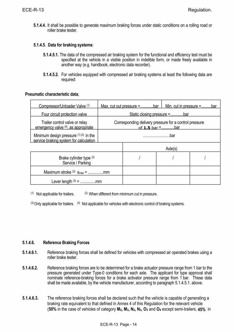
5.1.4.5.2. For vehicles equipped with compressed air braking systems at least the following data are
required:
Pneumatic characteristic data:
Compressor/Unloader Valve (1) Max. cut out pressure =.............bar Min. cut in pressure =..........bar Four circuit protection valve Static closing pressure =.............bar Trailer control valve or relay
emergency valve (4), as appropriate Corresponding delivery pressure for a control pressure
of 1.5 bar =.............bar Minimum design pressure (1) (2) in the service braking system for calculation
…………………bar
Axle(s)
Brake cylinder type (3) Service / Parking
/ / /
Maximum stroke (3) smax = ...............mm
Lever length (3) = ...............mm (1) Not applicable for trailers. (2) When different from minimum cut in pressure. (3) Only applicable for trailers. (4) Not applicable for vehicles with electronic control of braking systems. 5.1.4.6. Reference Braking Forces 5.1.4.6.1. Reference braking forces shall be defined for vehicles with compressed air operated brakes using a
roller brake tester. 5.1.4.6.2. Reference braking forces are to be determined for a brake actuator pressure range from 1 bar to the
pressure generated under Type-0 conditions for each axle. The applicant for type approval shall nominate reference-braking forces for a brake activator pressure range from 1 bar. These data shall be made available, by the vehicle manufacturer, according to paragraph 5.1.4.5.1. above.
5.1.4.6.3. The reference braking forces shall be declared such that the vehicle is capable of generating a
braking rate equivalent to that defined in Annex 4 of this Regulation for the relevant vehicle (50% in the case of vehicles of category M2, M3, N2, N3, O3 and O4 except semi-trailers, 45% in
Regulation ECE-R-13
ECE-R-13 Page - 15
the case of semi-trailers), whenever the measured roller braking force, for each axle irrespective of load, is not less than the reference braking force for a given brake actuator pressure within the declared operating pressure range */.
5.1.4.7. It shall be possible to verify, in a simple way, the correct operational status of those complex
electronic systems which have control over braking. If special information is needed, this shall be made freely available.
5.1.4.7.1. At the time of type approval, the means implemented to protect against simple unauthorized
modification to the operation of the verification means chosen by the manufacturer (e.g. warning signal), shall be confidentially outlined.
Alternatively, this protection requirement is fulfilled when a secondary means of checking the
correct operational status is available. 5.1.5. The requirements of Annex 18 shall be applied to the safety aspects of all Complex Electronic
Vehicle Control Systems which provide or form part of the control transmission of the braking function including those which utilise the braking system(s) for Automatically Commanded Braking or Selective Braking.
However, systems or functions, which use the braking system as the means of achieving a higher
level objective, are subject to Annex 18 only insofar as they have a direct effect on the braking system.
If such systems are provided, they must not be deactivated during Type Approval testing of the braking system
__________________ */ For the purpose of periodic technical inspection, the minimum limit braking rate values defined for the whole
vehicle may need adjustment to reflect National or International in-service requirements.
ECE-R-13 Regulation.
ECE-R-13 Page - 16
5.2. Characteristics of braking systems. 5.2.1. VEHICLES OF CATEGORIES M AND N. 5.2.1.1. The set of braking systems with which a vehicle is equipped shall satisfy the requirements laid down
for service, secondary and parking braking systems. 5.2.1.2. The systems providing service, secondary and parking braking may have common components so
long as they fulfil the following conditions: 5.2.1.2.1. There shall be at least two controls, independent of each other and readily accessible to the
driver from his normal driving position. For all categories of vehicles, except M2 and M3, every brake control (excluding a retarder control) shall be designed such that it returns to the fully-off position when released. This requirement shall not apply to a parking brake control (or that part of a combined control) when it is mechanically locked in an applied position;
5.2.1.2.2. the control of the service braking system shall be independent of the control of the parking braking system;
5.2.1.2.3. if the service braking system and the secondary braking system have the same control, the effectiveness of the linkage between that control and the different components of the transmission systems shall not be liable to diminish after a certain period of use;
5.2.1.2.4. if the service braking system and the secondary braking system have the same control, the
parking braking system must be so designed that it can be actuated when the vehicle is in motion. This requirement shall not apply if the vehicle's service braking system can be actuated, even partially, by means of an auxiliary control;
5.2.1.2.5. Without prejudice to the requirements of paragraph 5.1.2.3. of this Regulation, the service
braking system and the parking braking system may use common components in their transmission(s), provided that in the event of a failure in any part of the transmission(s) the requirements for secondary braking are still ensured;
5.2.1.2.6. in the event of breakage of any component other than the brakes (as defined in paragraph
2.6. of this Regulation) or the components referred to in paragraph 5.2.1.2.8. below, or of any other failure of the service braking system (malfunction, partial or total exhaustion of an energy reserve), the secondary braking system or that part of the service braking system which is not affected by the failure, shall be able to bring the vehicle to a halt in the conditions prescribed for secondary braking;
5.2.1.2.7. in particular, where the secondary braking system and the service braking system have a
common control and a common transmission: 5.2.1.2.7.1. if service braking is ensured by the action of the driver's muscular energy assisted by one
or more energy reserves, secondary braking shall, in the event of failure of that assistance, be capable of being ensured by the driver's muscular energy assisted by the energy reserves, if any, which are unaffected by the failure, the force applied to the control not exceeding the prescribed maxima;
5.2.1.2.7.2. if the service braking force and transmission depend exclusively on the use, controlled by
the driver, of an energy reserve, there must be at least two completely independent energy reserves, each provided with its own transmission likewise independent; each of them may act on the brakes of only two or more wheels so selected as to be capable of ensuring by themselves the prescribed degree of secondary braking without endangering the stability of the vehicle during braking; In addition, each of the aforesaid energy reserves shall be equipped with a warning device as defined in paragraph 5.2.1.13. below.
In each service braking circuit, in at least one of the air reservoirs, a device for draining
and exhausting is required in an adequate and easily accessible position.
Regulation ECE-R-13
ECE-R-13 Page - 17
5.2.1.2.7.3. If the service braking force and transmission depend exclusively on the use of an energy reserve, one energy reserve for the transmission is deemed to be sufficient, provided that the prescribed secondary braking is ensured by the action of the driver’s muscular energy acting on the service brake control and the requirements of paragraph 5.2.1.6. are met.
5.2.1.2.8. certain parts, such as the pedal and its bearing, the master cylinder and its piston or pistons (hydraulic systems), the control valve (hydraulic and/or pneumatic systems), the linkage between the pedal and the master cylinder or the control valve, the brake cylinders and their pistons (hydraulic and/or pneumatic systems), and the lever-and-cam assemblies of brakes, shall not be regarded as liable to breakage if they are amply dimensioned, are readily accessible for maintenance, and exhibit safety features at least equal to those prescribed for other essential components (such as the steering linkage) of the vehicle. Any such part as aforesaid whose failure would make it impossible to brake the vehicle with a degree of effectiveness at least equal to that prescribed for secondary braking shall be made of metal or of a material with equivalent characteristics and shall not undergo notable distortion in normal operation of the braking systems.
5.2.1.3. Where there are separate controls for the service braking system and the secondary braking
system, simultaneous actuation of the two controls shall not render both the service braking system and the secondary braking system inoperative, either when both braking systems are in good working order or when one of them is faulty.
5.2.1.4. The service braking system shall, whether or not it is combined with the secondary braking
system, be such that in the event of failure in a part of its transmission a sufficient number of wheels are still braked by actuation of the service brake control; these wheels must be so selected that the residual performance of the service braking system satisfies the requirements laid down in paragraph 2.4. of Annex 4 to this Regulation.
5.2.1.4.1. However, the foregoing provisions shall not apply to tractor vehicles for semi-trailers when
the transmission of the semi-trailer's service braking system is independent of that of the tractor vehicle's service braking system;
5.2.1.4.2. The failure of a part of a hydraulic transmission system shall be signalled to the driver by a
device comprising a red warning signal, as specified in paragraph 5.2.1.29.1.1. below. Alternatively, the lighting up of this device when the fluid in the reservoir is below a certain level specified by the manufacturer shall be permitted.
5.2.1.5. Where use is made of energy other than the muscular energy of the driver, there need not be more
than one source of such energy (hydraulic pump, air compressor, etc.), but the means by which the device constituting that source is driven shall be as safe as practicable.
5.2.1.5.1. In the event of failure in any part of the transmission of a braking system, the feed to the part
not affected by the failure shall continue to be ensured if required for the purpose of halting the vehicle with the degree of effectiveness prescribed for residual and/or secondary braking. This condition shall be met by means of devices which can be easily actuated when the vehicle is stationary, or by automatic means.
5.2.1.5.2. Furthermore, storage devices located down-circuit of this device shall be such that in the case
of a failure in the energy supply after 4 full-stroke actuations of the service brake control, under the conditions prescribed in paragraph 1.2. of Annex 7 to this Regulation, it is still possible to halt the vehicle at the 5th application, with the degree of effectiveness prescribed for secondary braking.
5.2.1.5.3. However, for hydraulic braking systems with stored energy, these provisions can be considered to be met provided that the requirements of paragraph 1.2.2. of Part C of Annex 7
to this Regulation, are satisfied.
ECE-R-13 Regulation.
ECE-R-13 Page - 18
5.2.1.6. The requirements of paragraphs 5.2.1.2. , 5.2.1.4. and 5.2.1.5. of this Regulation shall be met without the use of any automatic device of a kind such that its ineffectiveness might pass unnoticed through the fact that parts normally in a position of rest come into action only in the event of failure in the braking system.
5.2.1.7. The service braking system shall act on all wheels of the vehicle and shall distribute its action
appropriately among the axles.
5.2.1.7.1. In the case of vehicles with more than two axles, in order to avoid wheel-locking or glazing
of the brake linings, the brake force on certain axles may be reduced to zero automatically when carrying a much reduced load, provided that the vehicle meets all the performance requirements prescribed in Annex 4 to this Regulation.
5.2.1.7.2. In the case of N1 category vehicles with electric regenerative braking systems of category
B, the braking input from other sources of braking, may be suitably phased to allow the electric regenerative braking system alone to be applied, provided that both the following conditions are met:
5.2.1.7.2.1. Intrinsic variations in the torque output of the electrical regenerative braking system
(e.g. as a result of changes in the electric state of charge in the traction batteries) are automatically compensated by appropriate variation in the phasing relationship as long as the requirements 5/ of one of the following Annexes to this Regulation are satisfied: Annex 4, paragraph 1.3.2., or Annex 13 paragraph 5.3. (including the case with the electric motor engaged),
and also
5.2.1.7.2.2. Wherever necessary, to ensure that braking rate 5/ remains related to the driver’s braking demand, having regard to the available tyre/road adhesion, braking shall automatically be caused to act on all wheels of the vehicle.
5.2.1.8. The action of the service braking system shall be distributed between the wheels of one and the
same axle symmetrically in relation to the longitudinal median plane of the vehicle. Compensation and functions, such as anti-lock, which may cause deviations from this symmetrical distribution, shall be declared.
5.2.1.8.1. Compensation by the electric control transmission for deterioration or defect within the
braking system shall be indicated to the driver by means of the yellow warning signal specified in paragraph 5.2.1.29.1.2. below. This requirement shall apply for all conditions of loading when compensation exceeds the following limits:
5.2.1.8.1.1. a difference in transverse braking pressures on any axle: (a) of 25% of the higher value for vehicle decelerations ≥ 2m/sec2, (b) a value corresponding to 25% at 2m/sec2 for decelerations below this rate. _________________ 5/ The Authority, which is to grant approval, shall have the right to check the service braking system by additional
vehicle test procedures. 5.2.1.8.1.2. an individual compensating value on any axle: (a) > 50% of the nominal value for vehicle decelerations ≥ 2m/sec2,
Regulation ECE-R-13
ECE-R-13 Page - 19
(b) a value corresponding to 50% of the nominal value at 2m/sec2 for decelerations below this rate.
5.2.1.8.2. Compensation as defined above, is permitted only when the initial brake application is
made at vehicle speeds greater than 10 km/h. 5.2.1.9. Malfunctions of the electric control transmission shall not apply the brakes contrary to the
driver's intentions. 5.2.1.10. The service braking system and the parking braking system shall act on braking surfaces
permanently connected to the wheels through components of adequate strength.
Where braking torque for a particular axle or axles is provided by both a friction braking system and an electrical regenerative braking system of category B, disconnection of the latter source is permitted, providing that the friction braking source remains permanently connected and able to provide the compensation referred to in paragraph 5.2.1.7.2.1.
However in the case of short disconnection transients, incomplete compensation is accepted, but within 1s, this compensation shall have attained at least 75% of its final value.
Nevertheless, in all cases the permanently connected friction braking source shall ensure that
both the service and secondary braking systems continue to operate with the prescribed degree of effectiveness.
Disconnection of the braking surfaces of the parking braking system shall be permitted only
on condition that the disconnection is controlled exclusively by the driver from his driving seat, by a system incapable of being brought into action by a leak.
5.2.1.11. Wear of the brakes shall be capable of being easily taken up by means of a system of
manual or automatic adjustment. In addition, the control and the components of the transmission and of the brakes shall possess a reserve of travel and, if necessary, suitable means of compensation such that, when the brakes become heated, or the brake linings have reached a certain degree of wear, effective braking is ensured without immediate adjustment being necessary.
5.2.1.11.1. Wear adjustment shall be automatic for the service brakes. However, the fitting of
automatic adjustment devices is optional for off-road vehicles of categories N2 and N3 and for rear brakes of vehicles of categories N1 .
Brakes equipped with automatic wear adjustment devices shall, after heating followed
by cooling, be capable of free running as defined in paragraph 1.5.4. of Annex 4, following the Type - I test also defined in that Annex.
5.2.1.11.2. Checking the wear of the service brake friction components 5.2.1.11.2.1. It shall be possible to easily check this wear on service brake linings from the outside or
underside of the vehicle utilizing only the tools or equipment normally supplied with the vehicle, for instance by the provision of appropriate inspection holes or by some other means. Alternatively, acoustic or optical devices warning the driver at his driving position when lining replacement is necessary are acceptable. The yellow warning signal specified in paragraph 5.2.1.29.1.2. below may be used as the optical warning signal.
5.2.1.11.2.2. Assessment of the wear condition of the friction surfaces of the brake discs or drums may
only be performed by direct measurement of the actual components, which may necessitate some level of disassembly. Therefore, at the time of type approval, the vehicle manufacturer shall define the following: a) The method by which wear of the friction surfaces of drums and discs may be
assessed, including the level of disassembly required and the tools and process required to achieve this.
ECE-R-13 Regulation.
ECE-R-13 Page - 20
b) Information defining the maximum acceptable wear limit at the point at which replacement becomes necessary.
This information shall be made freely available eg. vehicle handbook or electronic data record.
5.2.1.12. In hydraulic-transmission braking systems, the filling ports of the fluid reservoirs shall be
readily accessible; in addition, the receptacles containing the reserve fluid shall be so designed and constructed that the level of the reserve fluid can be easily checked without the receptacles having to be opened. If this latter condition is not fulfilled, the red warning signal specified in paragraph 5.2.1.29.1.1. below shall draw the driver's attention to any fall in the level of reserve fluid liable to cause a failure of the braking system. The type of fluid to be used in the hydraulic transmission braking systems shall be identified by the symbol in accordance with figure 1 or 2 of ISO Standard 9128-1987. The symbol must be affixed in a visible position in indelible form within 100 mm of the filling ports of the fluid reservoirs; additional information may be provided by the manufacturer.
5.2.1.13. Warning device 5.2.1.13.1. Any vehicle fitted with a service brake actuated from an energy reservoir shall, where the
prescribed secondary braking performance cannot be obtained by means of this braking system without the use of the stored energy, be provided with a warning device, in addition to a pressure gauge, where fitted, giving an optical or acoustic signal when the stored energy, in any part of the system, falls to a value at which without re-charging of the reservoir and irrespective of the load conditions of the vehicle, it is possible to apply the service brake control a 5th time after 4 full-stroke actuations and obtain the prescribed secondary braking performance (without faults in the service brake transmission and with the brakes adjusted as closely as possible). This warning device shall be directly and permanently connected to the circuit.
When the engine is running under normal operating conditions and there are no faults in the braking system, as is the case in approval tests for this type, the warning device must give no signal except during the time required for charging the energy reservoir(s) after start-up of the engine. The red warning signal specified in paragraph 5.2.1.29.1.1. below shall be used as the optical warning signal.
5.2.1.13.1.1. However, in the case of vehicles which are only considered to comply with the requirements
of paragraph 5.2.1.5.1. of this Regulation by virtue of meeting the requirements of paragraph 1.2.2. of Part C of Annex 7 to this Regulation, the warning device shall consist of an acoustic signal in addition to an optical signal. These devices need not operate simultaneously, provided that each of them meet the above requirements and the acoustic signal is not actuated before the optical signal. The red warning signal specified in paragraph 5.2.1.29.1.1. below shall be used as the optical warning signal.
5.2.1.13.1.2. This acoustic device may be rendered inoperative while the handbrake is applied and/or, at
the choice of the manufacturer, in the case of automatic transmission, the selector is in the "Park" position.
5.2.1.14. Without prejudice to the requirements of paragraph 5.1.2.13. of this Regulation, where an auxiliary source of energy is essential to the functioning of a braking system, the reserve of energy shall be such as to ensure that, if the engine stops or in the event of a failure of the means by which the energy source is driven, the braking performance remains adequate to bring the vehicle to a halt in the prescribed conditions. In addition, if the muscular effort applied by the driver to the parking braking system is reinforced by a servo device, the actuation of the parking braking system shall be ensured in the event of a failure of the servo device, if necessary by using a reserve of energy independent of that normally supplying the servo device. This reserve of energy may be that intended for the service braking system.
5.2.1.15. In the case of a power-driven vehicle to which the coupling of a trailer, equipped with a brake
controlled by the driver of the towing vehicle, is authorized, the service braking system of the towing vehicle shall be equipped with a device so designed that in the event of failure of the
Regulation ECE-R-13
ECE-R-13 Page - 21
trailer's braking system, or in the event of an interruption in the air supply pipe (or of such other type of connection as may be adopted) between the towing vehicle and its trailer, it shall still be possible to brake the towing vehicle with the effectiveness prescribed for secondary braking; it is accordingly prescribed, in particular, that this device shall be situated on the towing vehicle.
5.2.1.16. The pneumatic/hydraulic auxiliary equipment must be supplied with energy in such a way
that during its operation the prescribed deceleration values can be reached and that even in the event of damage to the source of energy the operation of the auxiliary equipment cannot cause the reserves of energy feeding the braking systems to fall below the level indicated in paragraph 5.2.1.13. above.
5.2.1.17. If the trailer is of category O3 or O4, the service braking system shall be of the continuous or
semi-continuous type. 5.2.1.18. In the case of a vehicle authorized to tow a trailer of category O3 or O4, its braking systems
shall satisfy the following conditions: 5.2.1.18.1. when the towing vehicle's secondary braking system comes into action, there shall also be a
graduated braking action in the trailer; 5.2.1.18.2. in the event of failure of the towing vehicle's service braking system, where that system consists
of at least two independent parts, the part or parts not affected by the failure shall be capable of partially or fully actuating the brakes of the trailer.
It shall be possible to graduate this braking action. If this operation is achieved by a valve which is normally at rest, then such a valve may only be incorporated if its correct functioning can easily be checked by the driver, either from within the cab or from outside the vehicle, without the use of tools;
5.2.1.18.3. in the event of a failure (e.g. breakage of or leak) in one of the pneumatic connecting lines,
interruption or defect in the electric control line, it shall nevertheless be possible for the driver fully or partially to actuate the brakes of the trailer by means either of the service braking control or of the secondary braking control or of the parking braking control, unless the failure automatically causes the trailer to be braked with the performance prescribed in paragraph 3.3. of Annex 4 to this Regulation.
5.2.1.18.4. the automatic braking in paragraph 5.2.1.18.3. above shall be considered to be met when the
following conditions are fulfilled: 5.2.1.18.4.1. when the designated brake control of the controls mentioned in paragraph 5.2.1.18.3. above
is fully actuated, the pressure in the supply line shall fall to 1.5 bar within the following 2 seconds. In addition, when the brake control is released, the supply line shall be repressurized;
5.2.1.18.4.2. when the supply line is evacuated at the rate of at least 1 bar per second, the automatic
braking of the trailer shall start to operate before the pressure in the supply line falls to 2 bar. 5.2.1.18.5. In the event of a failure in one of the control lines connecting two vehicles equipped
according to paragraph 5.1.3.1.2., the control line not affected by the failure shall automatically ensure the braking performance prescribed for the trailer in paragraph 3.1. of Annex 4.
5.2.1.19. In the case of a power-driven vehicle equipped to draw a trailer with an electrical braking system,
according to paragraph 1.1. of Annex 14 to this Regulation, the following requirements shall be met: 5.2.1.19.1. the power supply of the power-driven vehicle shall have a sufficient capacity to provide the
current for an electrical braking system. With the engine running at the idling speed recommended by the manufacturer and all electrical devices supplied by the manufacturer as standard equipment of the vehicle switched on, the voltage in the electrical lines shall at maximum current consumption of the electrical braking system (15 A) not fall below the value of 9.6V measured at the connection. The electrical lines shall not be capable of short-
ECE-R-13 Regulation.
ECE-R-13 Page - 22
circuiting even when overloaded; 5.2.1.19.2. in the event of a failure in the towing vehicle's service braking system, where that system
consists of at least two independent parts, the part or parts not affected by the failure shall be capable of partially or fully actuating the brakes of the trailer;
5.2.1.19.3. the use of the stop-lamp switch and circuit for actuating the electrical braking system is
permissible only if the actuating line is connected in parallel with the stop-lamp and the existing stop-lamp switch and circuit are capable of taking the extra load.
5.2.1.20. In the case of a pneumatic service braking system comprising two or more independent
sections, any leakage between those sections at or downstream of the control shall be continuously vented to atmosphere.
5.2.1.21. In the case of a power-driven vehicle authorized to tow a trailer of category O3 or O4 , the service braking system of the trailer may only be operated in conjunction with the service, secondary or parking braking system of the towing vehicle. However, automatic application of the trailer brakes alone is permitted for the purpose of vehicle stabilisation.
5.2.1.22. Power-driven vehicles of categories M2 , M3 , N2 and N3 with not more than four axles shall be equipped with anti-lock systems of category 1 in accordance with Annex 13 to this Regulation.
5.2.1.23. With the exception of vehicles of categories N1 , power-driven vehicles equipped with an
electric control line and/or authorized to tow a trailer equipped with an anti-lock system, shall also be equipped with a special electrical connector, conforming to ISO 7638: 1997, for the electrical control transmission and/or the anti-lock systems of trailers.
5.2.1.24. Additional requirements for vehicles of categories M2, N1 and N2 < 5tonnes equipped with an
electric regenerative braking system. of category A: 5.2.1.24.1. The electric regenerative braking shall only be actuated by the accelerator control and/or
the gear selector neutral position for vehicles of category N1. 5.2.1.24.2. In addition, for vehicles of categories M2 and N2 ( < 5 tonnes), the electric regenerative
braking control can be a separate switch or lever. 5.2.1.24.3. The requirements of paragraphs 5.2.1.25.6. and 5.2.1.25.7. also apply to Category A
electric regenerative braking systems
5.2.1.25. Additional requirements for vehicles of categories M2, N1 and N2 < 5tonnes equipped with an electric regenerative braking system of category B:
5.2.1.25.1. It shall not be possible to disconnect partially or totally one part of the service braking
system other than by automatic means. This should not be construed as a departure from the requirements of paragraph 5.2.1.10
5.2.1.25.2. The service braking system shall have only one control device. 5.2.1.25.3. For vehicles fitted with an electric regenerative braking system of both categories, all the
relevant prescriptions shall apply except paragraph 5.2.1.25.1.1. above. In this case, the electric regenerative braking may be actuated by the accelerator control
and/or the gear selector neutral position for vehicles of category N1 Additionally, the action on the service braking control shall not reduce the above braking
Regulation ECE-R-13
ECE-R-13 Page - 23
effect generated by the release of accelerator control. 5.2.1.25.4. The service braking system shall not be adversely affected by the disengagement of the
motor(s) or by the gear ratio used. 5.2.1.25.5. If the operation of the electric component of braking is ensured by a relation established
between the information coming from the control of the service brake and the braking force at the respective wheels, a failure of this relation leading to the modification of the braking distribution among the axles (Annex 10 or 13, whichever is applicable) shall be signalled to the driver by an optical warning signal at the latest at the moment when the control is actuated and this signal shall remain lit as long as this defect exists and that the vehicle control switch (key) is in the "ON" position.
5.2.1.25.6. The operation of any electric regenerative braking must not be adversely affected by
magnetic or electric fields.
5.2.1.25.7. For vehicles equipped with an antilock device, the antilock device shall control the electric regenerative braking system of either Category.
5.2.1.26. Special additional requirements for the electric transmission of the Parking braking system: 5.2.1.26.1. In the case of a failure within the electric transmission, any unintended actuation of the parking
braking system shall be prevented. 5.2.1.26.2. In the case of a break in the wiring within the electric control transmission external to the
electronic control units and excluding the energy supply, or a failure in the control, it shall remain possible to apply the parking braking system from the driver's seat and thereby be capable of holding the laden vehicle stationary on an 8% up or down gradient. Alternatively, in this case, an automatic actuation of the parking brake is allowed when the vehicle is stationary, provided that the above performance is achieved and, once applied, the parking brake remains engaged independently of the status of the ignition (start) switch. In this alternative, the parking brake shall be automatically released as soon as the driver starts to set the vehicle in motion again. In the case of vehicles of category N1, the engine/manual transmission or the automatic transmission (park position) may be used to achieve or assist in achieving the above performance. It shall also be possible to release the parking braking system, if necessary by the use of tools and/or an auxiliary release device carried/fitted on the vehicle.
5.2.1.26.2.1. A break in the wiring within the electric transmission, or a failure in the control of the parking
braking system shall be signalled to the driver by the yellow warning signal specified in paragraph 5.2.1.29.1.2. When caused by a break in the wiring within the electric control transmission of the parking braking system, this yellow warning signal shall be signalled as soon as the break occurs.
In addition, such a failure in the control or break in the wiring external to the electronic
control unit(s) and excluding the energy supply, shall be signalled to the driver by flashing the RED warning signal specified in paragraph 5.2.1.29.1.1. as long as the ignition (start) switch is in the ON (run) position including a period of not less than 10 seconds thereafter and the control is in the ON (activated) position. Where actuation of the parking brake is normally indicated by a separate RED warning
ECE-R-13 Regulation.
ECE-R-13 Page - 24
signal, satisfying all the requirements of 5.2.1.29.3., this signal shall be used to satisfy the above requirement for a RED signal.
5.2.1.26.3. Auxiliary equipment may be supplied with energy from the electric transmission of the
parking braking system, provided that the supply of energy is sufficient to allow the actuation of the parking braking system in addition to the vehicle electrical load under non fault conditions.
In addition, where the energy reserve is also used by the service braking system, the requirements of paragraph 5.2.1.27.7. below shall apply.
5.2.1.26.4. After the ignition/start switch which controls the electrical energy for the braking equipment
has been switched off and/or the key removed, it shall remain possible to apply the parking braking system, whereas releasing shall be prevented.
5.2.1.27. Special additional requirements for service braking systems with electric control transmission: 5.2.1.27.1. With the parking brake released, the service braking system shall be able to generate a static total
braking force at least equivalent to that required by the prescribed Type-0 test, even when the ignition/start switch has been switched off and/or the key has been removed. In the case of power-driven vehicles authorized to tow trailers of category O3 or O4 , such vehicles shall provide a full control signal for the service braking system of the trailer. It should be understood that sufficient energy is available in the energy transmission of the service braking system.
5.2.1.27.2. In the case of a single temporary failure ( < 40ms ) within the electrical control transmission,
excluding its energy supply, (e.g. non-transmitted signal or data error) there shall be no distinguishable effect on the service braking performance.
5.2.1.27.3. A failure within the electric control transmission, 6/ not including its energy reserve, that affects
the function and performance of systems addressed in this Regulation,shall be indicated to the driver by the red or yellow warning signal specified in paragraphs 5.2.1.29.1.1. and 5.2.1.29.1.2. below, respectively, as appropriate. When the prescribed service braking performance can no longer be achieved (red warning) failures resulting from a loss of electrical continuity (eg. breakage, disconnection) shall be signalled to the driver as soon as they occur, and the prescribed residual braking performance shall be fulfilled by operating the service braking control in accordance with paragraph 2.4. of Annex 4 to this Regulation. These requirements shall not be construed as a departure from the requirements concerning secondary braking.
_________________________ 6/ Until uniform test procedures have been agreed, the manufacturer shall provide the Technical Service with an analysis
of potential failures within the control transmission and their effects. (see Annex 18) This information shall be subject to discussion and agreement between the Technical Service and the vehicle manufacturer.
5.2.1.27.4. A power-driven vehicle, electrically connected to a trailer via an electric control line, shall provide a
clear warning to the driver whenever the trailer provides the failure information that the stored energy in any part of the service braking system on the trailer falls below the warning level, as specified in paragraph 5.2.2.16. below.
A similar warning shall also be provided when a continuous failure ( > 40ms ) within the electric control transmission of the trailer, excluding its energy reserve, precludes achievement of the prescribed service braking performance of the trailer, as specified in paragraph 5.2.2.15.2.1. below. The red warning signal specified in paragraph 5.2.1.29.2.1. below shall be used for this purpose.
5.2.1.27.5. In the event of a failure of the energy source (alternator) of the electric control transmission,
starting from the nominal value of the (battery) energy level, the full control range of the service braking system shall be guaranteed after 20 consecutive full stroke actuations of the service braking control. During the test, the braking control shall be fully applied for 20 seconds and released for 5 seconds on each actuation.
Regulation ECE-R-13
ECE-R-13 Page - 25
It should be understood that during the above test sufficient energy is available in the energy transmission to ensure full actuation of the service braking system. This requirement shall not be construed as a departure from requirements of Annex 7.
5.2.1.27.6. When the battery voltage falls below a value nominated by the manufacturer at which the
prescribed service braking performance can no longer be guaranteed and/or which precludes at least two independent service braking circuits from each achieving the prescribed secondary or residual braking performance, the red warning signal specified in paragraph 5.2.1.29.1.1. below shall be activated.
After the warning signal has been activated, it shall be possible to apply the service braking control
and obtain at least the residual performance prescribed in paragraph 2.4. of Annex 4 to this Regulation. It should be understood that sufficient energy is available in the energy transmission of the service braking system. This requirement shall not be construed as a departure from the requirement concerning secondary braking.
5.2.1.27.7 If auxiliary equipment is supplied with energy from the same reserve as the electric control
transmission, it shall be ensured that, with the engine running at a speed not greater than 80% of the maximum power speed, the supply of the energy is sufficient to fulfil the prescribed deceleration values by either, provision of an energy supply which is able to prevent discharge of this reserve when all the auxiliary equipment is functioning or by automatically switching off pre-selected parts of the auxiliary equipment at a voltage above the critical level referred to in paragraph 5.2.1.27.6. of this Regulation, such that further discharge of this reserve is prevented.
Compliance with this requirement may be demonstrated by calculation or by a practical test. For vehicles authorized to tow a trailer of category O3 or O4, the energy consumption of the trailer shall be taken into account by a load of 400W. This paragraph does not apply to vehicles where the prescribed deceleration values can be reached without the use of electrical energy.
5.2.1.27.8. If the auxiliary equipment is supplied with energy from the electric control transmission, the
following requirements shall be fulfilled; 5.2.1.27.8.1. In the event of a failure in the energy source, whilst the vehicle is in motion, the energy in the
reservoir shall be sufficient to actuate the brakes when the control is applied.
5.2.1.27.8.2. In the event of a failure in the energy source, whilst the vehicle is stationary and the parking braking system applied, the energy in the reservoir shall be sufficient to actuate the lights even when the brakes are applied.
5.2.1.27.9. In the case of a failure in the electric control transmission of the service braking system of a towing vehicle equipped with an electric control line according to paragraph 5.1.3.1.2. or 5.1.3.1.3. above, the full actuation of the brakes of the trailer shall remain ensured.
5.2.1.27.10. In the case of a failure in the electric control transmission of a trailer, electrically connected via an electric control line only, according to paragraph 5.1.3.1.3., braking of the trailer shall be ensured according to paragraph 5.2.1.18.4.1.
This shall be the case whenever the trailer supplies the ‘supply line braking request’ signal via the data communication part of the electric control line or in the continuous absence of this data communication. This paragraph shall not apply to power driven vehicles which cannot be
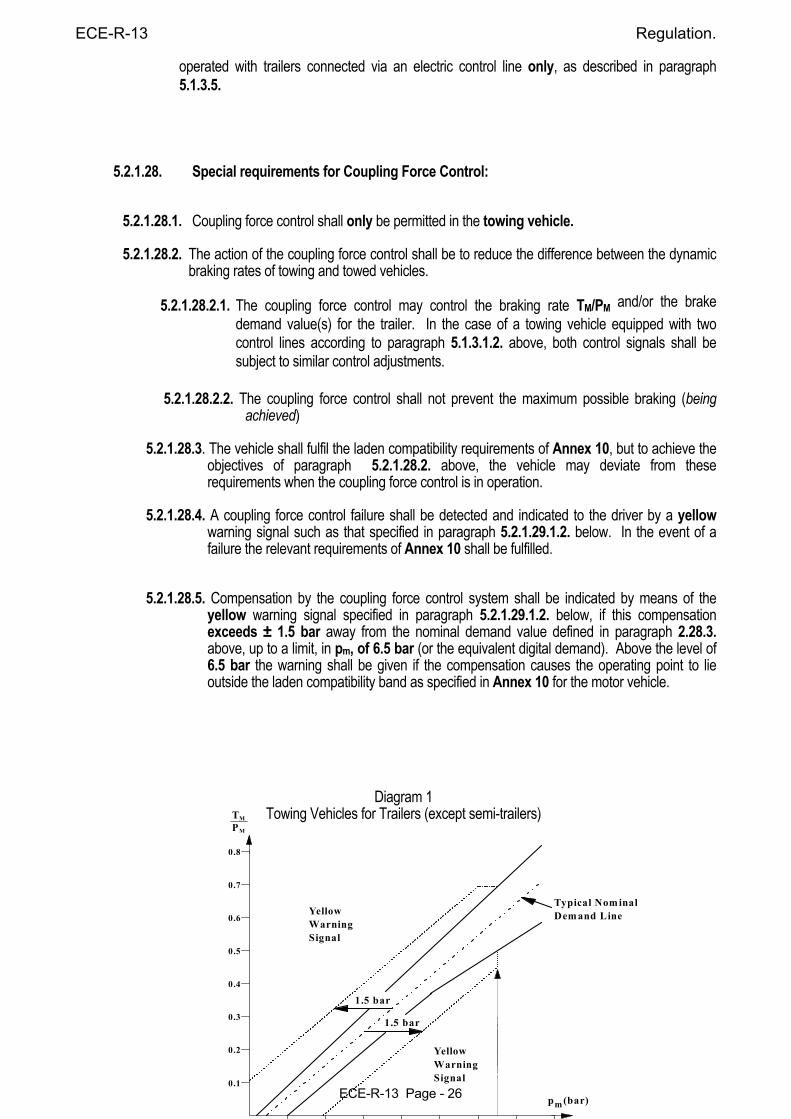
ECE-R-13 Regulation.
ECE-R-13 Page - 26
operated with trailers connected via an electric control line only, as described in paragraph 5.1.3.5.
5.2.1.28. Special requirements for Coupling Force Control: 5.2.1.28.1. Coupling force control shall only be permitted in the towing vehicle.
5.2.1.28.2. The action of the coupling force control shall be to reduce the difference between the dynamic braking rates of towing and towed vehicles.
5.2.1.28.2.1. The coupling force control may control the braking rate TM/PM and/or the brake
demand value(s) for the trailer. In the case of a towing vehicle equipped with two control lines according to paragraph 5.1.3.1.2. above, both control signals shall be subject to similar control adjustments.
5.2.1.28.2.2. The coupling force control shall not prevent the maximum possible braking (being
achieved)
5.2.1.28.3. The vehicle shall fulfil the laden compatibility requirements of Annex 10, but to achieve the objectives of paragraph 5.2.1.28.2. above, the vehicle may deviate from these requirements when the coupling force control is in operation.
5.2.1.28.4. A coupling force control failure shall be detected and indicated to the driver by a yellow
warning signal such as that specified in paragraph 5.2.1.29.1.2. below. In the event of a failure the relevant requirements of Annex 10 shall be fulfilled.
5.2.1.28.5. Compensation by the coupling force control system shall be indicated by means of the yellow warning signal specified in paragraph 5.2.1.29.1.2. below, if this compensation exceeds ± 1.5 bar away from the nominal demand value defined in paragraph 2.28.3. above, up to a limit, in pm, of 6.5 bar (or the equivalent digital demand). Above the level of 6.5 bar the warning shall be given if the compensation causes the operating point to lie outside the laden compatibility band as specified in Annex 10 for the motor vehicle.
Diagram 1 Towing Vehicles for Trailers (except semi-trailers)
0.8
0.7
0.6
0.5
0.4
0.3
0.2
0.1
1.5 bar
1.5 bar
YellowWarningSignal
YellowWarningSignal
Typical NominalDemand Line
p (bar)m
TP
M
M
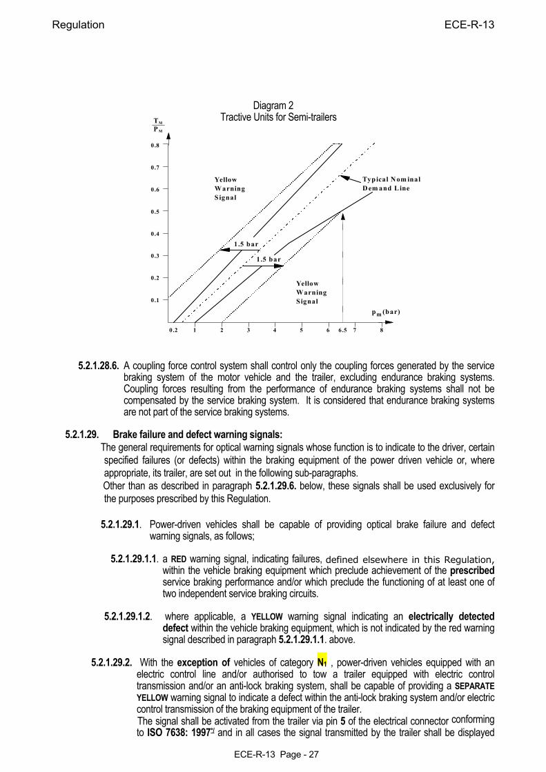
Regulation ECE-R-13
ECE-R-13 Page - 27
Diagram 2
Tractive Units for Semi-trailers 5.2.1.28.6. A coupling force control system shall control only the coupling forces generated by the service
braking system of the motor vehicle and the trailer, excluding endurance braking systems. Coupling forces resulting from the performance of endurance braking systems shall not be compensated by the service braking system. It is considered that endurance braking systems are not part of the service braking systems.
5.2.1.29. Brake failure and defect warning signals: The general requirements for optical warning signals whose function is to indicate to the driver, certain
specified failures (or defects) within the braking equipment of the power driven vehicle or, where appropriate, its trailer, are set out in the following sub-paragraphs.
Other than as described in paragraph 5.2.1.29.6. below, these signals shall be used exclusively for the purposes prescribed by this Regulation.
5.2.1.29.1. Power-driven vehicles shall be capable of providing optical brake failure and defect
warning signals, as follows;
5.2.1.29.1.1. a RED warning signal, indicating failures, defined elsewhere in this Regulation, within the vehicle braking equipment which preclude achievement of the prescribed service braking performance and/or which preclude the functioning of at least one of two independent service braking circuits.
5.2.1.29.1.2. where applicable, a YELLOW warning signal indicating an electrically detected
defect within the vehicle braking equipment, which is not indicated by the red warning signal described in paragraph 5.2.1.29.1.1. above.
5.2.1.29.2. With the exception of vehicles of category N1 , power-driven vehicles equipped with an
electric control line and/or authorised to tow a trailer equipped with electric control transmission and/or an anti-lock braking system, shall be capable of providing a SEPARATE YELLOW warning signal to indicate a defect within the anti-lock braking system and/or electric control transmission of the braking equipment of the trailer.
The signal shall be activated from the trailer via pin 5 of the electrical connector conforming to ISO 7638: 1997*/ and in all cases the signal transmitted by the trailer shall be displayed
0.8
0.7
0.6
0.5
0.4
0.3
0.2
0.1
0.2 1 2 3 4 5 6 7 86.5
1.5 bar
1.5 bar
YellowWarningSignal
YellowWarningSignal
Typical Nom inalD em and Line
p (bar)m
TP
M
M
ECE-R-13 Regulation.
ECE-R-13 Page - 28
without significant delay or modification by the towing vehicle.
This warning signal shall not light up when coupled to a trailer without an electric control line and/or electric control transmission and/or an anti-lock braking system or when no trailer is coupled. This function shall be automatic.
5.2.1.29.2.1. In the case of a power-driven vehicle equipped with an electric control line, when
electrically connected to a trailer with an electric control line, the red warning signal specified in paragraph 5.2.1.29.1.1. above, shall also be used to indicate certain specified failures within the braking equipment of the trailer, whenever the trailer provides corresponding failure information via the data communication part of the electric control line.
This indication shall be in addition to the yellow warning signal specified in paragraph
5.2.1.29.2. above. Alternatively, instead of utilizing the red warning signal specified in paragraph 5.2.1.29.1.1. above, and the accompanying yellow warning signal above, a separate red warning signal may be provided in the towing vehicle to indicate such a failure within the braking equipment of the trailer.
5.2.1.29.3. The warning signals shall be visible, even by daylight, the satisfactory condition of the
signals shall be easily verifiable by the driver from the driver's seat, the failure of a component of the warning devices shall not entail any loss of the braking system's performance.
5.2.1.29.4. Except where stated otherwise:
5.2.1.29.4.1. A specified failure or defect shall be signalled to the driver by the above mentioned warning signal(s) not later than on actuation of the relevant braking control.
5.2.1.29.4.2. The warning signal(s) shall remain displayed as long as the failure/defect persists and the ignition (start) switch is in the "on" (run) position; and
5.2.1.29.4.3. The warning signal shall be constant (non-flashing).
____________ */ Note that in all references to ISO 7638:1997, the connector may be used in 5 pin or 7 pin applications as appropriate. 5.2.1.29.5. The warning signal(s) mentioned above shall light up when the electrical equipment of the
vehicle (and the braking system) is energized. With the vehicle stationary, the braking system shall verify that none of the specified failures or defects are present before extinguishing the signals. Specified failures or defects which should activate the warning signals mentioned above, but which are not detected under static conditions, shall be stored upon detection and be displayed at start-up and at all times when the ignition (start) switch is in the "on" (run) position, as long as the failure or defect persists.
5.2.1.29.6. Non-specified failures (or defects), or other information concerning the brakes and/or running gear of the power driven vehicle, may be indicated by the yellow signal specified in paragraph 5.2.1.29.1.2. above, provided that all the following conditions are fulfilled:
5.2.1.29.6.1. The vehicle is stationary;
5.2.1.29.6.2. After the braking equipment is first energised and the signal has indicated that, following the procedures detailed in paragraph 5.2.1.29.5. above, no specified failures (or defects) have been identified; and
5.2.1.29.6.2.1. Non-specified faults or other information shall be indicated only by the flashing of the warning signal. However, the warning signal shall be extinguished by the time the
Regulation ECE-R-13
ECE-R-13 Page - 29
vehicle first exceeds 10 km/h. 5.2.2. VEHICLES OF CATEGORY O 5.2.2.1. Trailers of category O1 need not be equipped with a service braking system; however, if a
trailer of this category is equipped with a service braking system, it shall satisfy the same requirements as a trailer of category O2 .
5.2.2.2. Trailers of category O2 shall be equipped with a service braking system either of the
continuous or semi-continuous or of the inertia (overrun) type. The latter type shall be authorized only for trailers other than semi-trailers. However, electrical braking systems conforming to the requirements of Annex 14 to this Regulation shall be permitted.
5.2.2.3. Trailers of categories O3 and O4 shall be equipped with a service braking system of the
continuous or semi-continuous type. 5.2.2.4. The Service Braking system: 5.2.2.4.1. Shall act on all the wheels of the vehicle; 5.2.2.4.2. Shall distribute its action appropriately among the axles; 5.2.2.4.3. Shall contain in at least one of the air reservoirs, a device for draining and
exhausting in an adequate and easily accessible position. 5.2.2.5. The action of the service braking system shall be distributed between the wheels of one and
the same axle symmetrically in relation to the longitudinal median plane of the vehicle. Compensation and functions, such as anti-lock, which may cause deviations from this symmetrical distribution shall be declared 6/.
_______________
6/ Until uniform test procedures have been agreed, the manufacturer shall provide the Technical Service with an analysis of potential failures and their effects. (see Annex 18) This information shall be subject to discussion and agreement between the Technical Service and the manufacturer.
5.2.2.5.1. Compensation by the electric control transmission for deterioration or defect within the braking system shall be indicated to the driver by means of the separate yellow optical warning signal specified in paragraph 5.2.1.29.2. above. This requirement shall apply for all conditions of loading when compensation exceeds the following limits:
5.2.2.5.1.1. a difference in transverse braking pressures on any axle: (a) of 25% of the higher value for vehicle decelerations ≥ 2m/sec2, (b) a value corresponding to 25% at 2m/sec2 for decelerations below this rate. 5.2.2.5.1.2. an individual compensating value on any axle: (a) > 50% of the nominal value for vehicle decelerations ≥ 2m/sec2,
(b) a value corresponding to 50% of the nominal value at 2m/sec2 for decelerations below this rate.
5.2.2.5.2. Compensation as defined above, is permitted only when the initial brake application is
made at vehicle speeds greater than 10 km/h. 5.2.2.6. Malfunctions of the electric control transmission shall not apply the brakes contrary to the
driver's intentions.
ECE-R-13 Regulation.
ECE-R-13 Page - 30
5.2.2.7. The braking surfaces required to attain the prescribed degree of effectiveness must be in constant connection with the wheels, either rigidly or through components not liable to failure.
5.2.2.8. Wear of the brakes must be capable of being easily taken up by means of a system of manual or automatic adjustment. In addition, the control and the components of the transmission and of the brakes must possess a reserve of travel and, if necessary, suitable means of compensation such that, when the brakes become heated, or the brake linings have reached a certain degree of wear, effective braking is ensured without immediate adjustment being necessary.
5.2.2.8.1. Wear adjustment shall be automatic for the service brakes. However, the fitting of automatic adjustment devices is optional for vehicles of categories O1 and O2. Brakes equipped with automatic wear adjustment devices shall, after heating followed by cooling, be capable of normal running as defined in paragraph 1.7.3. of Annex 4 following the Type-I test or the Type-III test also defined in that Annex as appropriate.
5.2.2.8.1.1. In the case of trailers of category O4, the performance requirements of paragraph 5.2.2.8.1. above shall be deemed to be satisfied by fulfilling the requirements of paragraph 1.7.3. of Annex 4.
5.2.2.8.1.2. In the case of trailers of categories O2 and O3, the performance requirements of paragraph 5.2.2.8.1. above, shall be deemed to be satisfied by fulfilling the requirement of paragraph 1.7.3. of Annex 4. 7/
5.2.2.8.2. Checking the wear of the service brake friction components
5.2.2.8.2.1. It shall be possible to easily check this wear on service brake linings from the outside or underside of the vehicle utilizing only the tools or equipment normally supplied with the vehicle, for instance by the provision of appropriate inspection holes or by some other means.
____________________ 7/ Until uniform technical provisions have been agreed that correctly assess the function of the automatic brake
adjustment device, the free running requirement shall be deemed to be fulfilled when free running is observed during all brake tests prescribed for the relevant trailer.
5.2.2.8.2.2. Assessment of the wear condition of the friction surfaces of the brake discs or drums may
only be performed by direct measurement of the actual components, which may necessitate some level of disassembly. Therefore, at the time of type approval, the vehicle manufacturer shall define the following:
a) The method by which wear of the friction surfaces of drums and discs may be
assessed, including the level of disassembly required and the tools and process required to achieve this.
b) Information defining the maximum acceptable wear limit at the point at which
replacement becomes necessary.
This information shall be made freely available eg. vehicle handbook or electronic data record.
5.2.2.9. The braking systems shall be such that the trailer is stopped automatically if the coupling
separates while the trailer is in motion. However, this provision shall not apply to trailers with a maximum mass not exceeding 1.5 tonnes, on condition that the trailers are equipped with, in addition to the coupling device, a secondary coupling (chain, wire rope, etc.) capable, in the event of separation of the main coupling, of preventing the drawbar from touching the ground and providing some residual steering action on the trailer.
Regulation ECE-R-13
ECE-R-13 Page - 31
5.2.2.10. On every trailer which is required to be equipped with a service braking system, parking braking shall be assured even when the trailer is separated from the towing vehicle.
The parking braking device must be capable of being actuated by a person standing on the ground; however, in the case of a trailer used for the carriage of passengers, this brake must be capable of being actuated from inside the trailer.
5.2.2.11. If the trailer is fitted with a device enabling compressed-air actuation of the braking system
other than the parking braking system to be cut out, the first-mentioned system shall be so designed and constructed that it is positively restored to the position of rest not later than on resumption of the supply of compressed-air to the trailer.
5.2.2.12. Trailers of categories O3 and O4 shall satisfy the conditions specified in paragraph 5.2.1.18.4.2.
of this Regulation. An easily accessible pressure test connection is required downstream of the coupling head of the control line.
5.2.2.12.1. In the case of trailers equipped with an electric control line and electrically connected to a
towing vehicle with an electric control line the automatic braking action specified in paragraph 5.2.1.18.4.2. above, may be suppressed as long as the pressure in the compressed air reservoirs of the trailer is sufficient to ensure the braking performance specified in paragraph 3.3. of Annex 4 to this Regulation.
5.2.2.13. Trailers of categories O3 and O4 shall be equipped with anti-lock systems in accordance with
the requirements of Annex 13 to this Regulation. 5.2.2.14. Where the auxiliary equipment is supplied with energy from the service braking system, the
service braking system shall be protected to ensure that the sum of the braking forces exerted at the periphery of the wheels shall be at least 80% of the value prescribed for the relevant trailer as defined in paragraph 3.1.2.1. of Annex 4 to this Regulation.
This requirement shall be fulfilled under both of the following operating conditions:
During operation of the auxiliary equipment; and
In the event of breakage or leakage from the auxiliary equipment, unless such breakage or leakage affects the control signal referred to in paragraph 6. of Annex 10 to this Regulation, in which case the performance requirements of that paragraph shall apply.
5.2.2.14.1. The above provisions are deemed to be fulfilled when the pressure in the service brake storage device(s) is maintained at a pressure of at least 80% of the control line demand pressure or equivalent digital demand as defined in paragraph 3.1.2.2. of Annex 4 to this Regulation.
5.2.2.15. Special additional requirements for service braking systems with electric control transmission.
5.2.2.15.1. In the case of a single temporary failure ( < 40ms ) within the electric control transmission, excluding its energy supply, (e.g. non-transmitted signal or data error) there shall be no distinguishable effect on the service braking performance.
5.2.2.15.2. In the case of a failure within the electric control transmission 6/ (e.g. breakage, or disconnection), a braking performance of at least 30% of the prescribed performance for the service braking system of the relevant trailer shall be maintained. For trailers, electrically connected via an electric control line only, according to paragraph 5.1.3.1.3., and fulfilling 5.2.1.18.4.2. with the performance prescribed in paragraph 3.3 of Annex 4 to this Regulation, it is sufficient that the provisions of paragraph 5.2.1.27.10. are invoked, when a braking performance of at least 30% of that prescribed for the service braking system of the trailer, can no longer be ensured, either by providing the ‘supply line braking request’ signal via the data communication part of the electric control line or by (causing) the continuous absence of this data communication.
ECE-R-13 Regulation.
ECE-R-13 Page - 32
5.2.2.15.2.1. A failure within the electric control transmission of the trailer, not including its energy
reserve, that affects the function and performance of systems addressed by this Regulation, shall be indicated to the driver by the separate (yellow) warning signal specified in paragraph 5.2.1.29.2. via pin 5 of the electrical connector conforming to ISO 7638: 1997 (in 5 or 7 pin form)
In addition, trailers equipped with an electric control line, when electrically connected to a
towing vehicle with an electric control line, shall provide the failure information for activation of the red warning signal specified in paragraph 5.2.1.29.2.1. above, via the data communication part of the electric control line, when the prescribed service braking
5.2.2.16. When the stored energy in any part of the service braking system of a trailer equipped with an electric control line and electrically connected to a towing vehicle with an electric control line falls to the value determined in accordance with paragraph 5.2.2.16.1. below, a warning shall be provided to the driver of the towing vehicle.
The warning shall be provided by activation of the red signal specified in paragraph 5.2.1.29.2.1. above, and the trailer shall provide the failure information via the data communication part of the electric control line. The separate yellow warning signal specified in paragraph 5.2.1.29.2. above, shall also be activated via pin 5 of the electrical connector conforming to ISO 7638: 1997 */ , to indicate to the driver that the low-energy situation is on the trailer.
5.2.2.16.1. The low-energy value referred to in paragraph 5.2.2.16. above shall be that at which,
without re-charging of the energy reservoir and irrespective of the load condition of the trailer, it is not possible to apply the service braking control a fifth time after four full-stroke actuations and obtain at least 50% of the prescribed performance of the service braking system of the relevant trailer.
____________________ 6/ Until uniform test procedures have been agreed, the manufacturer shall provide the Technical Service with an
analysis of potential failures and their effects. This information shall be subject to discussion and agreement between the Technical Service and the manufacturer.
5.2.2.17. Trailers equipped with an electric control line and O3 and O4 category trailers equipped with an
anti-lock system, shall be fitted with a special electrical connector for the braking system and/or anti-lock system, conforming to ISO 7638: 1997. 9/ */ Failure warning signals required from the trailer by this Regulation shall be activated via the above connector. The requirement to be applied to trailers with respect to the transmission of failure warning signals, shall be those as appropriate, which are prescribed for motor vehicles in paragraphs 5.2.1.29.4, 5.2.1.29.5 and 5.2.1.29.6.
5.2.2.17.1. Trailers that utilise selective braking as a means to enhance vehicle stability shall, in the event
of a failure within the electric control transmission of the stability system, indicate the failure by the separate yellow warning signal specified in paragraph 5.2.1.29.2. above (via pin 5 of the ISO 7638:1997 */ connector).
Note: This requirement shall be kept under review during subsequent amendments to
Regulation No. 13 pending:
(i) an amendment to the ISO 11992 data communication Standard that includes a message to indicate a failure within the electric control transmission of the trailer stability control system; and
(ii) vehicles equipped to that Standard are in general use.
Regulation ECE-R-13
ECE-R-13 Page - 33
5.2.2.18. Whenever power supplied by the ISO 7638 connector is used for the functions defined in paragraph 5.1.3.6. above, the braking system shall have priority and be protected from an overload external to the braking system. This protection shall be a function of the braking system.
5.2.2.19. In the case of a failure in one of the control lines connecting two vehicles equipped according
to paragraph 5.1.3.1.2. above, the trailer shall use the control line not affected by the failure to ensure, automatically, the braking performance prescribed for the trailer in paragraph 3.1. of Annex 4.
5.2.2.20. When the supply voltage to the trailer falls below a value nominated by the manufacturer at
which the prescribed service braking performance can no longer be guaranteed, the separate yellow warning signal specified in paragraph 5.2.1.29.2. above, shall be activated via pin 5 of the ISO 7638: 1997 connector. In addition, trailers equipped with an electrical control line, when electrically connected to a towing vehicle with an electric control line, shall provide the failure information for activation of the) red warning signal specified in paragraph 5.2.1.29.2.1. above, via the data communication part of the electric control line.
6. TESTS.
Braking tests which the vehicles submitted for approval are required to undergo, and the braking performance required, are described in Annex 4 to this Regulation.
____________________
9/ The wiring specifications of ISO 7638: 1997 for the trailer not equipped with an electric control transmission may be reduced if the trailer is installed with its own independent fuse. The rating of this fuse shall be such that the current rating of the conductors is not exceeded.
*/ Note that in all references to ISO 7638:1997, the connector may be used in 5 pin or 7 pin applications as
appropriate. 7. MODIFICATION OF VEHICLE TYPE OR BRAKING SYSTEM AND EXTENSION OF APPROVAL. 7.1. Every modification of the vehicle type or of its braking equipment with regard to the characteristics in
Annex 2 to this Regulation shall be notified to the administrative department which approved the vehicle type. That department may then either :
7.1.1. consider that the modifications made are unlikely to have an appreciable adverse effect and that in any
case the vehicle still meets the requirements; or 7.1.2. require a further report from the Technical Service responsible for carrying out the tests. 7.2. Notice of confirmation, extension or refusal of approval shall be communicated by the procedure
specified in paragraph 4.3. above, to the Parties to the Agreement which apply this Regulation. 7.3. The competent authority issuing the extension of approval shall assign a series number to each
communication form drawn up for such an extension and inform thereof the other Contracting Parties to the Agreement by means of a communication document conforming to the model in Annex 2 to this Regulation.
8. CONFORMITY OF PRODUCTION. 8.1. A vehicle approved to this Regulation shall be so manufactured as to conform to the type approved by
meeting the requirements set forth in paragraph 5. above. 8.2. In order to verify that the requirements of paragraph 8.1. above are met, suitable controls of the
production shall be carried out.
ECE-R-13 Regulation.
ECE-R-13 Page - 34
8.3. The holder of the approval shall in particular : 8.3.1. ensure existence of procedures for the effective control of the quality of products; 8.3.2. have access to the control equipment necessary for checking the conformity to each approved type; 8.3.3. ensure that data of test results are recorded and that annexed documents shall remain available for a
period to be determined in accordance with the Administrative Service; 8.3.4. analyse the results of each type of test, in order to verify and ensure the stability of the product
characteristics making allowance for variation of an industrial production; 8.3.5. ensure that for each type of product, the tests or some of them, prescribed in this Regulation are
carried out; 8.3.6. ensure that any samples or test pieces giving evidence of non-conformity with the type of test
considered shall give rise to another sampling and another test. All the necessary steps shall be taken to re-establish the conformity of the corresponding production.
8.4. The competent authority which has granted type approval may at any time verify the conformity control
methods applicable to each production unit. 8.4.1. At every inspection, test books and production survey records shall be presented to the visiting inspector. 8.4.2. The inspector may take samples at random which will be tested in the manufacturer's laboratory. The
minimum number of samples may be determined according to the results of the manufacturer's own verification.
8.4.3. When the quality level appears unsatisfactory or when it seems necessary to verify the validity of the
tests carried out in application of paragraph 8.4.2. above, the inspector shall select samples to be sent to the Technical Service which has conducted the type approval tests.
8.4.4. The competent authority may carry out any test prescribed in this Regulation. 8.4.5. The normal frequency of inspections by the competent authority shall be one every two years. If unsatisfactory results are recorded during one of these visits, the competent authority shall ensure that
all necessary steps are taken to re-establish the conformity of production as rapidly as possible. 9. PENALTIES FOR NON-CONFORMITY OF PRODUCTION. 9.1. The approval granted in respect of a vehicle type pursuant to this Regulation may be withdrawn if the
requirements laid down in paragraph 8.1. above, are not complied with. 9.2. If a Contracting Party to the Agreement which applies this Regulation withdraws an approval it has
previously granted, it shall forthwith so notify the other Contracting Parties applying this Regulation by means of a copy of a communication form conforming to the model in Annex 2 to this Regulation.
10. PRODUCTION DEFINITELY DISCONTINUED. If the holder of the approval completely ceases to manufacture a type of vehicle approved in accordance
with this Regulation, he shall so inform the authority which granted the approval. Upon receiving the relevant communication, that authority shall inform thereof the other Contracting Parties to the Agreement applying this Regulation by means of copies of a communication form conforming to the model in Annex 2 to this Regulation.
11. NAMES AND ADDRESSES OF THE TECHNICAL SERVICES CONDUCTING APPROVAL TESTS AND OF ADMINISTRATIVE DEPARTMENTS.
The Parties to the Agreement applying this Regulation shall communicate to the United Nations Secretariat the names and addresses of the Technical Services responsible for conducting approval tests and of the administrative departments which grant approval and to which forms certifying approval or extension or refusal or withdrawal of approval, issued in other countries, are to be sent.
12. TRANSITIONAL PROVISIONS.
Regulation ECE-R-13
ECE-R-13 Page - 35
12.1. General 12.1.2.1. Subject to the provisions of paragraph 12.2. below, as from 1 October 1996 Contracting Parties
applying this Regulation shall grant approvals only if the vehicle type to be approved meets the requirements of this Regulation as amended by the 08 or 09 series of amendments.
12.1.1.1. As from the official date of entry into force of Supplement 8 to the 09 series of Amendments, no
Contracting Party applying this Regulation shall refuse to grant ECE approval under this Regulation as amended by Supplement 8 to the 09 series of amendments.
12.1.2. New type approvals 12.1.2.1. Subject to the provisions of paragraph 12.2. below, as from 1 October 1996 Contracting Parties
applying this Regulation shall grant approvals only if the vehicle type to be approved meets the requirements of this Regulation as amended by the 08 or 09 series of amendments.
12.1.2.2. Subject to the provisions of paragraph 12.2. below, as from 1 October 1998 Contracting Parties
applying this Regulation shall grant approvals only if the vehicle type to be approved meets the requirements of this Regulation as amended by the 09 series of amendments.
12.1.2.3. During the 24 months' period that follows the date of entry into force of Supplement 8
to the
09 series of amendments, Contracting Parties applying this Regulation shall grant ECE approvals only if the vehicle type to be approved meets either:
12.1.2.3.1. the requirements of this Regulation as amended by Supplement 8 to the 09 series of
Amendments, or 12.1.2.3.2. the requirements of paragraphs 5.2.1.11.2 and 5.2.2.8.2 of this Regulation as amended by
Supplement 7 to the 09 series of amendments, together with all other requirements of this Regulation as amended by Supplement 8 to the 09 series of amendments.
12.1.2.4. As from 24 months after the official date of entry into force of Supplement 8 to the 09 series
of amendments, Contracting Parties applying this Regulation shall grant ECE approvals only if the vehicle type to be approved meets the requirements of this Regulation as amended by Supplement 8 to the 09 series of amendments.
12.1.3. Limit of validity of old type approvals
12.1.3.1. Subject to the provisions of paragraphs 12.1.3.3. and 12.2. below, approvals granted to this Regulation, as amended by the 06 or 07 series of amendments, shall cease to be valid on 1 October 1998 unless the Contracting Party which granted the approval notifies the other Contracting Parties applying this Regulation that the vehicle type approved meets the requirements of this Regulation as amended by the 08 or 09 series of amendments.
12.1.3.2. Subject to the provisions of paragraphs 12.1.3.3. and 12.2. below, approvals granted to this
Regulation, as amended by the 08 series of amendments, shall cease to be valid on 1 October 2000 unless the Contracting Party which granted the approval notifies the other Contracting Parties applying this Regulation that the vehicle type approved meets the requirements of this Regulation as amended by the 09 series of amendments.
12.1.3.3. For vehicles of category N1, approvals granted to the 06 series of amendments to this Regulation
before 1 July 1995 and any extensions of approvals issued subsequently shall remain valid until 1 April 2001. However this derogation does not extend to the requirements contained in paragraph 5.1.1.3. of this Regulation which shall apply to all new vehicles from 1 October 1998.
12.2. Anti-lock braking Systems. In place of the dates specified in paragraphs 12.1.2. and 12.1.3. above, the requirement for anti-lock
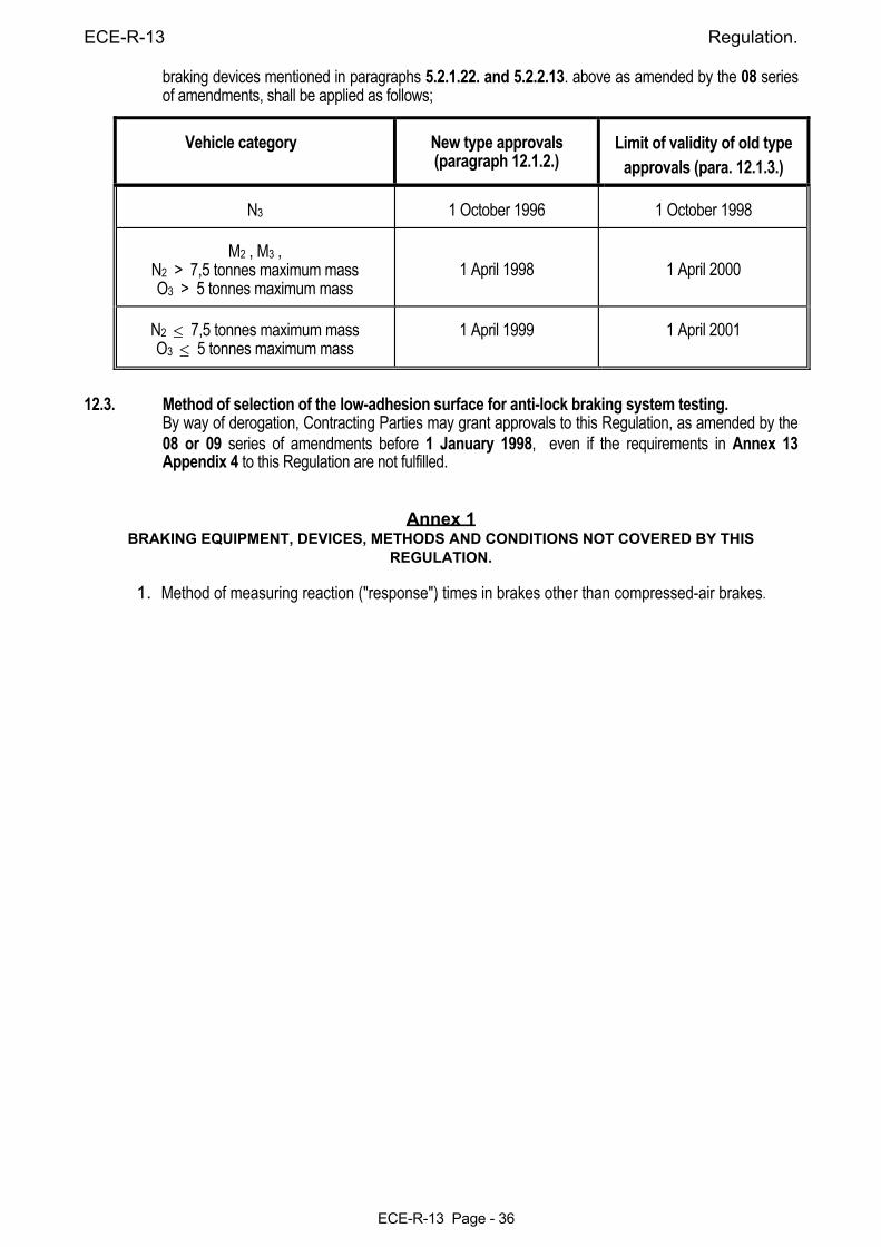
ECE-R-13 Regulation.
ECE-R-13 Page - 36
braking devices mentioned in paragraphs 5.2.1.22. and 5.2.2.13. above as amended by the 08 series of amendments, shall be applied as follows;
Vehicle category New type approvals
(paragraph 12.1.2.) Limit of validity of old type
approvals (para. 12.1.3.)
N3 1 October 1996 1 October 1998
M2 , M3 , N2 > 7,5 tonnes maximum mass O3 > 5 tonnes maximum mass
1 April 1998
1 April 2000
N2 ≤ 7,5 tonnes maximum mass O3 ≤ 5 tonnes maximum mass
1 April 1999 1 April 2001
12.3. Method of selection of the low-adhesion surface for anti-lock braking system testing. By way of derogation, Contracting Parties may grant approvals to this Regulation, as amended by the
08 or 09 series of amendments before 1 January 1998, even if the requirements in Annex 13 Appendix 4 to this Regulation are not fulfilled.
Annex 1 BRAKING EQUIPMENT, DEVICES, METHODS AND CONDITIONS NOT COVERED BY THIS
REGULATION.
1. Method of measuring reaction ("response") times in brakes other than compressed-air brakes.