Embed Size (px)
Citation preview

1
Instruction manualSecond Ed i t ion, October 2011
ECoSBoost Digital Amplifier
ESU P/N 04011-10679
2
Content
1. EG Declaration of Confirmity ................................3
2. WEEE-Declaration .................................................3
3. Important Remarks-Please read this chapter first ...3
4. Introduction – Why Booster? ................................4
5. Unpacking and starting up ...................................45.1. Content of package ..............................................45.2. Locating the device ...............................................45.2.1. Screw the device tight ........................................4
6. Features of the ECoSBoost ...................................56.1. Power Amplifier ....................................................56.1.1. Fan control .........................................................56.2. Data formats .........................................................56.2.1. What does M4 mean? ........................................56.3. mfx® feedback .....................................................56.4. DCC RailCom® feedback ......................................56.5. ECoSlink ...............................................................5
7. Appropriate digital command stations ..................57.1. ESU ECoS ..............................................................57.2. Märklin® central station® .....................................5
8. Power supply ........................................................68.1. Power supply ........................................................68.2. Power supply unit .................................................68.2.1. 5A Power supply ...............................................68.2.1.1. Setting the input voltage and output voltage...68.2.1.2. Practical voltage settings .................................68.2.2. 9A Power supply ...............................................78.2.3. Connections .......................................................78.3. Track connection ..................................................78.3.1. Wiring two-conductor tracks ..............................88.3.2. Wiring three-conductor tracks ............................88.4. ECoSlink connection .............................................88.5. Status-LED ............................................................9
9. Dividing the layout ...............................................99.1. Power section .......................................................99.2. Separate circuit for magnetic accessories ...............99.3. Transition from digital into analog sections ............9
10. How to configure the ECoSBoost .....................1010.1. Change the name of the booster.......................1010.2. Set maximum current ........................................1010.3. Change the short-circuit behaviour ....................10
11. Software-Updates ............................................10
12. Stop” and “Go” button ...................................11
13. Current monitor of the ECoS/Central Station ....11
14. Support and Assistance ....................................11
Copyright 1998 - 2011 by ESU electronic solutions ulm GmbH & Co KG. Mistakes, changes resulting in technical advancement, availability and all other rights reserved. Electrical and mechanical characteristics, dimensions and sketches are subject to change without prior notice. ESU may not be held responsible for any damage or consequential loss or damage caused by inappropriate use of the product, abnormal operating conditions, unau-thorised modifications to the product, etc. Not suitable for children under 14 years of age. Inappropriate use may result in injury due to sharp points and edges.
Märklin® is a registered trademark of Gebr. Märklin® und Cie. GmbH, Göp-pingen, Germany. RailCom® is a registered trademark of Lenz Elektronik GmbH, Giessen. RailComPlus® is a registered trademark of Lenz Elektronik GmbH, Giessen. All other trademarks are the property of their respective legal owners.
According to its policy ESU electronic solutions ulm GmbH & Co KG conti-nues to develop its products. Therefore ESU reserves the right to implement changes and improvements to any of the products listed in the ESU docu-mentation.
Duplication and preproduction of this documentation in any shape or form requires prior written consent from ESU.
15. ECoS System overview ......................................12
16. Technical data ..................................................1316.1. Technical data ECoSBoost 4A 50010 .................1316.2. Technical data ECoSBoost 8A 50011 .................13
17. Warranty Certificate .........................................15

3
Declaration of Confirmity
1. EG Declaration of ConfirmityWe, ESU electronic solutions ulm GmbH & Co. KG, Edisonallee 29, D-89231 Neu-Ulm, Germany, declare herewith in sole responsibili-ty compliance of the product ECoSBoost 4A 50010ECoSBoost 8A 50011to which this declaration is related to, with the following stan-dards:EN 71 1-3 : 1988 / 6 : 1994 – EN 50088 : 1996 – EN 55014, Part 1 + Part 2 : 1993EN 61000-3-2 : 1995 – EN 60742 : 1995 – EN 61558-2-7 : 1998According to the guidelines as per88 / 378 / EWG – 89 / 336 / EWG – 73 / 23 / EWGthe ECoSBoost bears the CE mark.
2. WEEE-DeclarationDisposal of old electrical and electronic devices (applicable in the European Union and other European countries with separate coll-ection system).
This mark on the product, the packaging or the relevant documentation indicates, that this product may not be treated as ordinary household garbage. Instead this product has to be delivered to a suitable disposal point for recycling of electrical or electronic equipment. By disposing of this product in the appropria-te manner you help to avoid negative impact on the environment and health that could be
caused by inappropriate disposal. Recycling of materials contribu-tes to conserve our natural environment. For more information on recycling this product please contact your local administration, the rubbish disposal service or the shop where you have purchased this product.
Batteries do not belong into household trash!Please do not dispose of discharged batteries in your household trash: take them to a collection point at your local town hall or dealer. Thus you assure an environmentally friendly way of dis-posal.
3. Important Remarks-Please read this chapter firstWe congratulate you to your purchase of an ESU ECoSBoost di-gital amplifier.This manual will guide you step by step through the multitude of possibilities of the ECoSBoost. However, have one request:Please read this manual carefully prior to initial operation. Alt-hough the ECoSBoost is robustly constructed there is the risk of damage due to incorrect wiring. If in doubt, avoid any „costly” experiments!
•ECoSBoost isonly intendedfor theusewithelectricalmodeltrain layouts. Never operate ECoSBoost without paying atten-tion and never use it for controlling devices designed for trans-porting persons.
•ECoSBoostisnotatoy.Makesurethatchildrenusethisdeviceonly when adults are present.
•Only use the power supply provided for ECoSBoost. Othertransformers may lead to reduced output or in extreme cases to damage of the command station.
•UsethepowersupplyprovidedwithECoSBoostfortheenergysupply for ECoSBoost only and not for any other household appliances.
•NeveruseY-adaptersinordertoprovidepowertootherdevicesfor your model trains! An unintended connection to ground could lead to damage or destruction of your ECoSBoost or the connected command station!
•Checkthepowersupplyregularlyfordamageonthehousingor the main cable. Damaged parts may not be used under any circumstances! Do not attempt to repair the power supply! This may be fatal!
•Assureadequateventilationofthepowersupply.Donotinstallin furniture without sufficient air circulation since this could lead to overheating or fire!
•AssureadequateventilationoftheECoSBoost.Donotinstallinfurniture without sufficient air circulation since this could lead to overheating or fire!
•ECoSBoostmayonlybeoperatedwith thedevicesdescribedin this manual. Even if other devices (also from other suppliers) may have the same plugs and sockets does this not automa-tically indicate that such devices may be operated with ECoS-Boost. Any other use as described here is not permitted.
•Adhere to the wiring diagrams shown in this manual whenconnecting your layout. Other circuitry could lead to damage of ECoSBoost or your command station.
•DonotdropyourECoSBoostcommandstationorsubjectittomechanical impact or vibrations. Such rough treatment could cause breakage of components within the device.
•NeverexposeyourECoSBoosttorain,humidityordirectsun-light. In case of high temperature variations (e.g. when you take your ECoSBoost from the cold car to your comfortably heated house) please wait for a few hours until the device has adjusted to the temperature before switching it on.

4
Introduction & Starting up
Figure 1
5. Unpacking and starting upThe ECoSBoost is safely protected in a carton with a two-part blis-ter when delivered. Please keep the packaging and this manual in a safe place for later use. Only the original packaging guarantees protection from transport damage.
5.1. Content of packagePlease check that all items are contained in the package immedi-ately after opening it.
•ECoSBoostdigitalamplifier•For50010:powersupply90VA•For50011:powersupply180VA•SeparatepowersupplycableforEurosockets•SeparatepowersupplycableforUSsockets•Onepieceof2-poletrackconnectorterminal•Instructionmanual(thisbooklet)
If one of the components mentioned here should be missing, ple-ase contact your retailer or dealer immediately.
5.2. Locating the devicePlace the ECoSBoost on a flat, clean and dry surface within sight of your model train layout.. Provide suitable conditions for your ECoSBoost: ideally operate the ECoSBoost at room temperature. Avoid heat sources in the immediate surroundings. Put up your ECoSBoost in such a way that the cooling slits at the front are not covered. Only then a sufficient air circulation will be ensured. Please consider that the fans start temperature-controlled and might produce exhaust air.
5.2.1. Screw the device tightTheECoSBoostcanbedirectlyscrewedontothelayout.Youjustneed to remove the (only attached) transparent cover and using wood screws, secure through the ECoSBoost as shown in figure 1.
•WhenusingECoSBoostoutsideyoumustprotect itfromtheelements under all circumstances! Only keep ECoSBoost out-side as long as you run trains and avoid temperatures below 8° Celsius or above 30° Celsius.
•Donotuseanyaggressivechemicals,cleaningsolutionsorsol-vents for cleaning ECoSBoost. Never use liquids or spray for cleaning the monitor. Instead use a clean slightly (!) moist cloth and only when ECoSBoost is switched off.
•DonotattempttoopenECoSBoost.
WarningYourmodel railway layoutmustneverbe leftunattended!Anunnoticed short circuit may lead to fire risk due to heating!
4. Introduction – Why Booster?As with analogue, a sufficient power supply for the layout is essen-tial for the safe operation of your ECoS command station or your Märklin® central station®. All power consuming devices on the layout such as locomotives, wagon lighting sets, turnouts, signals etc. have to be powered with energy.This task is performed by the so-called “boosters”.Boosters amplify the track signals produced by the digital com-mand station and power the connected track section.Both the ESU ECoS as well as the Märklin® central station ® have installed such a booster. If the power consumption of all running trains is however, higher than the maximum current the command station is able to supply, you must divide your layout in to sections. Every section will be powered by its own booster. The ECoSBoost is exactly meant to be for this task. It is perfectly prepared for being used with the ESU ECoS or the Märklin® central station®.The question, whether additional boosters are needed, cannot be answered easily in practice as it is difficult to determine the actual power requirement of your layout.Youcanroughlyestimatethepowerrequirementasfollows:Running locos without LokSound: Gauge N: Between 350mA and 600mAGauge H0: Between 450mA and 1000mABig gauges: Between 750mA and 2000mARunning locos with LokSound:Gauge N or H0: Between 450mA and 1100mABig gauges: Between 1500mA and 3500mAInterior lighting: ca. 50mA per bulb or LEDTurnout motor: Between 500mA and 1500mA

5
6. Features of the ECoSBoostThe ECoSBoost is available in two versions which, respectively, have a different maximum output.
6.1. Power AmplifierThe integrated power amplifier of the ECoSBoost corresponds ex-actly to the internal booster of the ECoS.
•TheECoSBoost4Aversion50010isabletosupplythetracksec-tion with an output current of up to 4 Ampere. It is meant for gauges N, TT and H0.
•TheECoSBoost8Aversion50011isabletosupplythetracksec-tion with an output current of up to 8 Ampere. It is meant for gauges 0, I and G.
Never operate the 8A version with H0 or even smaller-sized lay-outs, during a short circuit your locomotives can be irreparably damaged.
6.1.1. Fan controlEvery ECoSBoost comes with one (50010) or respectively two (50011) fans, which start to cool the booster from a certain tem-perature. The start-up of the fan(s) cannot be influenced from the outside. As soon as the temperature has fallen to a normal level, the fan(s) will switch off.After switch on, the fan(s) will shortly run for 3.5 seconds. This is a normal procedure and may not be considered as a malfunction.
6.2. Data formatsThe ECoSBoost can basically amplify and output the following data formats:
•DCC•Märklin®Motorola®•Selectrix®•M4/mfx®
Only the command station is able to create data formats and de-liver them to the tracks. The ECoSBoost itself can amplify the sig-nals, not create them.
6.2.1. What does M4 mean?At some points in this catalog you will notice the term „M4“ for the first time rightly wonder what this might mean.
This question can be answered quite simply: from 2009 forward, M4 is the name data pro-tocol that was chosen by ESU to be implemen-ted in their decoders. Decoders with the M4 protocol are one hundred percent compatible with command using mfx®. At such stations (e.g. Märklin® Central Station®) they will be recognized automatically and all playing func-
tions are available just like when using mfx® other hand, our ESU command stations using M4 will recognize all (Märklin® and mfx® decoders without any restrictions and will still work without any problems. the (mutual) inventor of mfx® we can assure you of this. In short: the technique stays the same, only the name has been changed.
6.3. mfx® feedbackEvery ECoSBoost has an integrated mfx® feedback module. When the ECoSBoost is connected to a mfx®-compatible command sta-tion, e.g. the Märklin® central station, all locomotives that are equipped with a mfx® decoder will be recognised. The ECoSBoost is 100% compatible with mfx®.
6.4. DCC RailCom® feedbackEach ECoSBoost is equipped with a “global detector” for the bi-directional NMRA DCC transmission (“RailCom”). This makes the communication between appropriate DCC decoders and the com-mand station possible.
6.5. ECoSlinkEach ECoSBoost is connected to the digital command station via the ECoSlink bus. The appropriate bus cable is included in the pa-ckaging of every ECoSBoost. The ECoSlink bus enables the booster to receive track signals as well as control and status messages at the same time. Like every other device connected to the ECoSlink, the ECoSBoost will be recognised by the command station and can also be easily configured this way. Thus you are also able to assign any name to each ECoSBoost. Furthermore, the maximum output current of each ECoSBoost can be configured individually as well as the short-circuit behaviour (compare chapter 10.3.).Since it is possible to connect up to 128 devices to the ECoSlink, your layout may grow without limitation. Each ECoSBoost repre-sents an independent device.If needed, the command station will transfer new firmware versi-ons onto the ECoSBoost, therefore it is always possible to extend the functionality of the ECoSBoost in this manner.
7. Appropriate digital command stationsThe ECoSBoost is appropriate for every digital command station with an ECoSlink-“busmaster”.
7.1. ESU ECoSThe ECoSBoost can be operated with every ESU ECoS command station. ECoSBoost is able to generate the following data formats: DCC, Motorola® and Selectrix®. A RailCom® feedback is possible, however, the ECoS must have a firmwareversionhigherthan1.1.0.YoumighthavetoupdatetheECoS first to this software version before you can use the ECoS-Boost. The most recent version of the ECoS software is always available at www.esu.eu via the ECoS support forum.
7.2. Märklin® central station®The ECoSBoost can be also used with the Märklin® central station®. ECoSBoost is able to generate the mfx® and Motorola® data for-mat. The mfx® feedback is fully guaranteed. The Märklin® central station® must have software version 2.0.4 or highertobeabletorecognisetheECoSBoost.Youmighthavetoupdate the central station® first to this software version before you can use the ECoSBoost. Please contact your dealer regarding the update or refer to our web-site www.esu.eu for further information.
Features & Appropriate command stations
6
8. Power supply
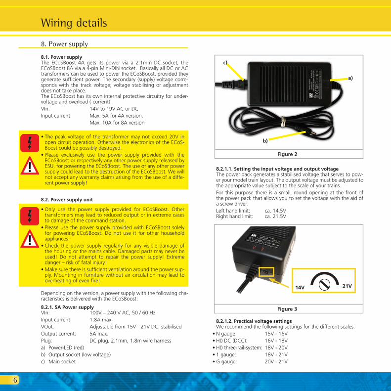
8.1. Power supplyThe ECoSBoost 4A gets its power via a 2.1mm DC-socket, the ECoSBoost 8A via a 4-pin Mini-DIN socket. Basically all DC or AC transformers can be used to power the ECoSBoost, provided they generate sufficient power. The secondary (supply) voltage corre-sponds with the track voltage; voltage stabilising or adjustment does not take place. The ECoSBoost has its own internal protective circuitry for under-voltage and overload (-current).VIn: 14Vto19VACorDCInput current: Max. 5A for 4A version, Max. 10A for 8A version
•Thepeakvoltageof the transformermaynotexceed20V inopen circuit operation. Otherwise the electronics of the ECoS-Boost could be possibly destroyed.
•Please exclusively use the power supply provided with theECoSBoost or respectively any other power supply released by ESU, for powering the ECoSBoost. The use of any other power supply could lead to the destruction of the ECoSBoost. We will not accept any warranty claims arising from the use of a diffe-rent power supply!
8.2. Power supply unit
•Only use the power supply provided for ECoSBoost. Othertransformers may lead to reduced output or in extreme cases to damage of the command station.
•Pleaseuse thepower supplyprovidedwithECoSBoost solelyfor powering ECoSBoost. Do not use it for other household appliances.
•Check the power supply regularly for any visible damage ofthe housing or the mains cable. Damaged parts may never be used! Do not attempt to repair the power supply! Extreme danger – risk of fatal injury!
•Makesurethereissufficientventilationaroundthepowersup-ply. Mounting in furniture without air circulation may lead to overheating of even fire!
Depending on the version, a power supply with the following cha-racteristics is delivered with the ECoSBoost:
8.2.1. 5A Power supply VIn: 100V–240VAC,50/60HzInput current: 1.8A max.VOut: Adjustablefrom15V-21VDC,stabilisedOutput current: 5A max.Plug: DC plug, 2.1mm, 1.8m wire harnessa) Power-LED (red)b) Output socket (low voltage)c) Main socket
Wiring details
Figure 2
a)
b)
c)
8.2.1.1. Setting the input voltage and output voltageThe power pack generates a stabilised voltage that serves to pow-er your model train layout. The output voltage must be adjusted to the appropriate value subject to the scale of your trains.For this purpose there is a small, round opening at the front of the power pack that allows you to set the voltage with the aid of a screw driver:Lefthandlimit: ca.14.5VRighthandlimit: ca.21.5V
8.2.1.2. Practical voltage settingsWe recommend the following settings for the different scales:
•Ngauge: 15V-16V•H0DC(DCC): 16V-18V•H0three-rail-system: 18V-20V•1gauge: 18V-21V•Ggauge: 20V-21V
Figure 3
14V 21V

7
8.2.2. 9A Power supply VIn: 100V–240VAC,50/60HzInput current: 3.6A max.VOut: 19VDC,stabilisiertOutput current: 9.5A max.Plug: 4-pin power Mini-DIN plug, 1.8m wire harness
a) Power-LED (red)b) Output socket (low voltage)c) Main socket
Figure 4
a)
b)
c)
8.2.3. Connections•Firstofallconnectthepowersupplycablewiththecorresponding
socket of the power supply. Then plug the cable in an appropriate power socket. Figure 4 shows how to the power supply can be connected to the ECoSBoostBoost.
•ToECoSBoostBoost4A50010:thepowersupplywillbeconnec-ted via a 2.1mm DC socket.
•ToECoSBoostBoost8A50011:thepowersupplywillbeconnec-ted via a 4-pin Mini-DIN socket.NeveruseYadapters forconnecting thepowersupply tootherdevices of your model railway layout besides the ECoSBoostBoost! This could cause an inadmissible contact to ground that could lead to the destruction of your ECoSBoostBoost!The power supply generates a stabilised voltage that serves to po-weryourmodel train layout.Avoltageof18Vcanbe toohighfor some N gauge decoders or locos. Therefore, we recommend a lower track voltage when using the ECoSBoostBoost 4A for N gauge layouts.
8.3. Track connection The tracks are connected via a two-way socket with a removable plug. Please make sure that you use cables of adequate size (cross-section) for your track power. We recommend wires of at least 0.75mm² (better: 1.5mm²) cross section. In larger layouts connect track power every two meters to the tracks.ECoSBoost uses an H4-bridge (full bridge) for the track power. Therefore with ECoSBoostBoost – contrary to older Märklin® sys-tems - there is no „Common” (Ground).
Wiring details
ECoSBoost 4A 50010
ECoSBoost 8A 50011
Figure 5

8
8.3.2. Wiring three-conductor tracksPlease pay attention to the right polarity, as otherwise some older decoders (e.g. k83) will not work.
Wiring takes place as shown. If your new Motorola® locos work but the old k83 accessory decoders and older Märklin® locos do not it is most likely that polarity has been swapped.Märklin® offers a suitable connecting track for the C-track system. Part number 74046 is not suitable! For the K track system you should use the connecting track No. 2290.
8.4. ECoSlink connectionViathebuscablethatisincludedindelivery,theECoSBoostcanbe connected to one of the ECoSlink-Connect sockets of the com-mand station. Please make sure that the cable is in the correct position.
Wiring details
Figure 6
•Neverconnectanotherdigitalsystemoranaloguetransformerto the same circuit as the ECoSBoostBoost. The ECoSBoost-Boost may be damaged or destroyed!
•Dependingontherespectiveversion,theECoSBoostBoostsup-plies up to 8A track current. Always consider if you actually need such a high output current. In case of a short circuit your locos may be damaged and there may be risk of fire! Also refer to chapter 10.2 regarding the current reduction.
•Please always ensure that thepolarityof all track sections isidentical! Terminal “B” of the first ECoSBoostBoost and ter-minal „B“ of the following booster must be connected to the same side of the track! Otherwise, this will lead to short-circuits whenever a locomotive crosses the district boundaries between the sections!
Remove all capacitors that may possibly haven been wired to the track power supply cable in your layout. They would cause a strong heat build-up of the booster and impair the power output. Almost in every connecting track in an analogue starter kit (Roco®, Mär-klin®) are, respectively were, capacitors installed.
8.3.1. Wiring two-conductor tracksWiring takes place as shown. Polarity is not an issue (for DCC or Selectrix®).
Supply area 1 Supply area 2
Isolated tracks on both sides!
Figure 7
Supply area 1 Supply area 2
Isolate the middle conductor!
Figure 8
ECoSlink Connect, 7pin
Booster connection cable
6pin
Figure 9

9
To avoid incorrect connection the amount of contact pins varies on both sides. Please only use the supplied cable that comes with the delivery. Make sure the position of the pins is correct when you plug the cable in.Don´t exert to much pressure, the pins could break or bend!If there are to connect more than three ECoSBoost devices, the ECoS link-Bus can be extended via the Märklin® Terminal, orde-ring no. 60125.
8.5. Status-LEDThe ECoSBoost has a green status LED on its top. It shows the current operating mode:
LED out: No voltage supply or ECoSBoost Booster re ceives new firmware („update“) from com- mand station.
LED continuously on: Normal operating mode: connection to command station is established, track voltage is applied.
LED flashing short-long: No connection to command station: Power supply is OK, but ECoSlink- cable is not, resp. not correctly connected.
LED flashing slowly: Connection to command station is establis- hed, track voltage is switched off.
LED flashing quickly: Connection to command station is establis- hed, track voltage is switched off due to overload or short-circuit.
Figure 10
Status-LED (under transparent cover)
9. Dividing the layoutTo ensure a trouble-free operation of your layout, proper planning of the track sections is essential. We are glad to assist you here with some ideas.
9.1. Power sectionPlease consider the arrangement of the power sections very ca-refully! Assign the transitions between each of the single booster sections in a way they are rarely passed by trains. The following divisions are useful:
•Station/Depot•Mainline(probablydividedinseveralsections)•Side/branch-line(probablydividedinseveralsections)
Regardless of the size of each single circuit, there should be a cur-rent supply from the booster to the tracks every 1.5 – 2 metres: as the transition resistance of the track sections is not negligible, the omission to feed the tracks every 1.5 – 2 metres may lead to a fai-ling short-circuit detection due to voltage drops within the tracks.
If vehicles, which are far away from the feeding point slow down, it is – in most cases - a sign of insufficient power supply.
Each circuit needs to be separated by a single-pole isolation. This means to disrupt the contact studs of three-conductor tracks and at least one of the two-conductor tracks.We recommend only using boosters of the same type. In a mixed operation it is likely that problems may occur whenever a loco-motive crosses a district boundary due to a greatly varying time related behaviour and track voltage. If a mixed operation is, however, unavoidable, it must be noted that a rocker contact for separating the centre rail is required at the district boundaries.Furthermore, the track voltage of every district boundary should be as high as possible and at the same level.Please make sure that locomotives or trains do not stop directly on a joint and bridge two district boundaries. Hereby, the outputs of both boosters will be electrically connected. Depending on the layout of the boosters and, respectively, their supply voltage equa-lizing currents might flow which will lead to the destruction of the booster after some time.
9.2. Separate circuit for magnetic accessoriesFor larger layouts we recommend to use another booster to switch all the magnet accessories separately. In this way it will be still possible to switch magnetic accessories, if the track is powered off, e.g. by a short circuit. This will increase the operating safety significantly.
9.3. Transition from digital into analog sectionsWith a transition from a digital section into an analogue supplied section there are certain things you must pay attention to. The track separation as explained in chapter 8.3. will not be sufficient here.Youhavetoisolatethedigitalpartofyourlayoutfromtheana-logue on both sides at the transition points in order to avoid an electrical contact. To do so, please either use isolating track con-nectors or saw the track profiles.
Dividing the layout

10
10.1. Change the name of the boosterThe default factory name of the booster can be changed at any time, so it is easier to distinguish the boosters. The name set will remain even when used with another command station.
10.2. Set maximum currentIn the choice list “Current limit of the internal booster” you can reduce the maximum current if so desired. Never set the current limit to a higher value as necessary in order to avoid damage or welded rails in case of a short circuit.
10.3. Change the short-circuit behaviourYou are able to determine the short-circuit behaviour of eachbooster separately.If the respective booster causes the shot circuit itself, it will switch off the tracks in every case and signalise the switch-off by its LED status. Due to security reasons you will not be able to take any influence on this behaviour. However, if you active the option “Ignore short circuit of other boosters”, the ECoSBoost will not switch off when the short cir-cuit took place in another booster section. By doing so, each sin-gle booster can be set to remain switched on, although there has been a short circuit within another layout section.Especially on larger layouts it is useful to activate this option for all the boosters connected: so only the booster in whose section the short circuit took place will be switched off. This makes trouble-shooting much easier.If magnetic accessory decoders are powered by a separate ECoS-Boost, as described in chapter 9.2., this booster should also ignore the short circuits of other boosters to make sure that in case of a malfunction it is still able to switch turnouts and signals.Independent from all the settings made here, all ECoSBoost de-vices will always switch off if you press the “Stop” button of your ECoSBoost, resp. central station®. In this case the “Stop” button has priority.
11. Software-UpdatesThe ECoSBoost software can be also updated for the ECoSlink bus, like any other device. Thus it is possible to upgrade new functions or remove week points.An update can only be carried out when the booster is connected to a command station. Every time you switch on the ECoSBoost, the command station will check if a latest firmware is available and will update all the boosters connected automatically. New firmwa-re for boosters is therefore always an integrated part of the central software. During the update the boosters cannot be accessed, the LED sta-tus shuts off. The status bar of the command station will show an update symbol.
How to configure the ECoSBoost
However, there would be a short circuit caused by the wheels anyway between the digital and the normal traction current that could destroy the ECoSBoost. To avoid this problem you need to install a separation module between the digital and the analogue section. For two-conductor tracks we recommend to use the e.g. ROCO 10768. It switches the supply of the joint section between the digital and the analogue section immediately when a short circuit occurs through crossing. For three-conductor tracks we recommend to use track rockers as well as a both-sided track isolation (also the outer conductors!).
10. How to configure the ECoSBoostAfter being connected, the ECoSBoost can be used right from the start. The command station recognises the booster automatically and integrates it into the system. This will take a few seconds. If the registration was successful, the status LED of the ECoSBoost will light steadily (compare chapter 8.5). However, it can be useful to change some of the settings.All settings are carried out directly on the ECoSBoost / central sta-tion ®. As described in chapter 20.3. of the ECoSBoost manual, all the ECoSBoost devices connected will be listed in the setup menu, submenu “ECoSlink devices”.
Youareabletoadjustthesettingsbyselectingtheboosterdesiredin the setup menu “ECoSlink devices”, then click onto the “Edit” button.
Figure 11
Figure 12

11
12. Stop” and “Go” buttonIf you have at least one or more ECoSBoost devices connected to your command station, the behaviour of the Stop- and Go-buttons will change.After briefly pushing the “Stop” button the command station will immediately interrupt the track current and all external boosters. The display shows “Emergency Stop”, the red “Stop” button is lit. Use the “Stop” button in case of danger or when you place or remove a loco on or from the tracks. If the boosters are configured to switch off in case of a short circuit or an overload, the “Stop” button will also blink red.The “Go” button releases the “Emergency Stop“, resp. the short circuit. The internal and the external boosters are re-activated. Operation may continue.If the “Go” button blinks green then at least one ECoSBoost boos-ter in the system has been shut down due to a short circuit. Howe-ver, at least one booster remains active. In this operating status all boosters can be re-activated by pressing the “Go” button.
13. Current monitor of the ECoS/Central StationThe current monitor provides valuable information regarding the energy demand of your layout. With its assistance you can deter-mine the actual power consumption of your layout and thus better plan its power districts. From ECoS software version 1.1.0 or central station® 2.0.4. you will find the current monitor in the set-up menu by pressing the respective symbol:
a) List of all internal boosters in the systemb) Separate display for every ECoSBoostc) Display for external DCC or 6017 boostersd) Present current / maximum currente) Bar display of weighted average (tendence)
Figure 13
a)
c)
b)
d) e) f) g)
f) Present track voltage in the booster districtg) Present internal temperature of the boosterThe current monitor will always offer you an overview over your layout´s current supply situation. The current monitor also shows which booster has been switched off due to a short circuit.
14. Support and AssistanceYourmodeltraindealerorhobbyshopisyourcompetentpartnerfor all questions regarding your LokPilot decoder. In fact he is your competent partner for all questions around model trains.There are many ways to get in touch with us. For enquiries please use either email, fax (please provide your fax-no. or email address) or go to www.esu.eu/en/forum and we will reply within a few days.Please call our hotline only in case of complex enquiries that can’t be dealt with by email or fax. The hotline is often very busy and you may encounter delays. Rather send an email or fax and also checkourwebsiteformoreinformation.Youwillfindmanyhintsunder “Support / FAQ” and even feedback from other users that may help you with your particular question. Of course we will always assist you; please contact us at:
USA & Canada (English support), please contact:Phone: +1 (570) 649-5048 Tuesday & Thursday 9:00am - 3:00pm (CT)Fax: +1 (866) 591-6440 Email: [email protected]: ESU LLC 477 Knopp Drive US-PA-17756 Muncy
Germany and all other countries, please contact: Fax: +49 (0) 731 - 1 84 78 - 299Email: www.esu.eu/en/forumMail: ESU GmbH & Co. KG - Technical support - Edisonallee 29 D-89231 Neu-Ulm
www.esu.eu
Strommonitor ECoS & Support & Hilfe

12
Figure 14
ECoS System overview
15. ECoS System overview
13
16. Technical data
16.1. Technical data ECoSBoost 4A 50010
Hardware
H4 booster with 4.0 A continuous output power. Output is over-load and short-circuit protected. Thermally overload protection. Galvanically separation of track output and ECoSlink bus.NMRA DCC BiDirectional feedback module “RailCom®” with in-tegrated cutout-device.Integrated mfx® feedback module / M4
Operational modes
Use with ESU ECoSBoost or Märklin® central station.Supported data formats: DCC, Motorola®, Selectrix®, mfx®, M4
Dimensions
180 x 76 x 40 mm (7 x 3 x 1.5 inch)
Included in delivery
ECoSBoostwith4.0Aoutputpower,powersupply15-21V /5A(120-240VA),connectingterminalsfortrackconnection,detailedinstruction manual
16.2. Technical data ECoSBoost 8A 50011
Hardware
H4 booster with 8.0 A continuous output power. Output is over-load and short-circuit protected. Thermally overload protection. Galvanically separation of track output and ECoSlink bus.NMRA DCC BiDirectional feedback module “RailCom®” with in-tegrated cutout-device.Integrated mfx® feedback module / M4
Operational modes
Use with ESU ECoSBoost or Märklin® central station.Supported data formats: DCC, Motorola®, Selectrix®, mfx®, M4
Dimensions
180 x 76 x 40 mm (7 x 3 x 1.5 inch)
Included in delivery
ECoSBoostwith8.0Aoutputpower,powersupply15-21V /5A(120-240VA),connectingterminalsfortrackconnection,detailedinstruction manual
Technical data
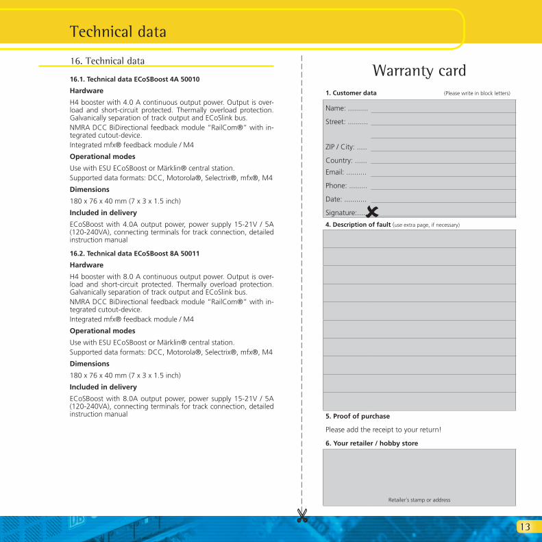
Warranty card1. Customer data (Please write in block letters)
Name: ..........
Street: ..........
ZIP / City: .....
Country: ......
Email: ..........
Phone: .........
Date: ...........
Signature:.....
4. Description of fault (use extra page, if necessary)
5. Proof of purchase
Please add the receipt to your return!
6. Your retailer / hobby store
Retailer´s stamp or address
û
_
_ _
_ _
_ _
_ _
_ _
_ _
_ _
_ _
_ _
_ _
_ _
_ _
_ _
_ _
_ _
_ _
_ _
_ _
_ _
_ _
_ _
_ _
_ _
_ _
_ _
_ _
_ _
_

14
Notes

15
17. Warranty Certificate24 Months warranty form date of purchase
Dear customer,Congratulations on purchasing this ESU product. This quality product was manufactured applying the most advanced production methods and processes and was subject to stringent quality checks and tests.Therefore ESU electronic solutions ulm GmbH & Co. KG grants you a warranty for the purchase of ESU products that far exceeds the national warranty as governed by legislation in your country and beyond the warranty from your authorised ESU dealer, ESU grants an extended
Manufacturer’s warranty of 24 months from date of purchase
Warranty conditions:
This warranty is valid for all ESU products that have been purchased from an authorised ESU dealer.Any service, repair or replacement under this warranty requires proof of purchase. The filled in warranty certificate together with the receipt from your ESU dealer serves as proof of purchase. We recommend keeping the warranty certificate together with the receipt.In case of a claim please fill in the enclosed failure report card as detailed and precise as possible and return it with your faulty product.Please use the appropriate postage when shipping to ESU.
Extent of warranty / exclusions:
This warranty covers the repair or replacement free of charge at the discretion of ESU electronic solutions ulm GmbH & Co. KG of any faulty parts that are caused by design faults or faults in production, material or transport. Any further claims are explicitly excluded.
The warranty expires:
1. In case of wear and tear due to normal use.2. In case of conversions of ESU – products with parts not approved by the manufacturer.3. In case of modification of parts.4. In case of inappropriate use (different to the intended use as specified by the manufacturer).5. If the instructions as laid down in the user manual by ESU electronic solutions ulm GmbH & Co. KG were not adhered to.
There is no extension of the warranty period due to any repairs carried out by ESU or re-placements. Youmaysubmityourwarrantyclaimeitherwithyourdealerorbyshippingtheproductinquestionwiththewarrantycertificate,thereceiptofpurchase and the fault description directly to ESU electronic solutions ulm GmbH & Co. KG at:
Electronic solutions ulm GmbH & Co. KG- Service department - Edisonallee 29D - 89231 Neu-UlmGERMANY
Warranty Certificate

16
ESU P/N 04011-10679