Embed Size (px)
Citation preview

® Specif icat ion Submittal page
Job Name:
Job Number:
Model Numbers:
EcoSystem® Five Control Input Digital Dimming Ballasts
369-454c 1 2.29.12
Digital electronic dimming ballasts maximize the benefits of a lighting management system. EcoSystem® Ballasts offer 100% to 10% dimming; ideal for use where saving energy, increasing flexibility, and maximizing productivity are the goals of the lighting design.
Features
•Continuous,flicker-freedimmingfrom100%to10%•Availablewithandwithoutanintegralsensor
connection•Integralsensorconnectionprovidespowerforand
responds to one occupancy sensor, one photo sensor, and one personal control input (infrared receiver or wallstation)
•CommunicatesstatusandsensorinputsovertheEcoSystem®digitallink
•Programmedrapidstartdesignensuresfullratedlamp life while dimming and cycling
•Lampsturnontoanydimmedlevelwithoutflashingtofull brightness
•Lowharmonicdistortionthroughouttheentiredimming range
•Frequencyofoperationensuresthatballastdoesnotinterfere with infrared devices
•End-of-lamp-lifeprotectioncircuitryensuressafeoperation throughout entire lamp life
•Ultra-quietoperation•Nonvolatilememoryrestoresallballastsettingsafter
power failure•Ballastsmaintainconsistentlightoutputforlinearlamp
lengths (i.e. 4 ft [1.5 m], 3 ft [1 m], 2 ft [0.5 m] have same relative output)
•Protectedfrommiswiresofanyinputpowertocontrollead, or from lamp leads to each other and/or ground
•100%performancetestedatfactory•Customballastfactorsavailable.
Design tool and specifications can be found at www.lutron.com/ballasttool
EcoSystem® case type G
EcoSystem® case type J
EcoSystem® Multiple Control Input Ballasts

® Specif icat ion Submittal page
Job Name:
Job Number:
Model Numbers:
EcoSystem® Five Control Input Digital Dimming Ballasts
369-454c 2 2.29.12
Specifications
Standards
•CaliforniaEnergyCommission(CEC)Listed*•ULListed(evaluatedtotherequirementsofUL935)•CSAcertified(evaluatedtotherequirementsofC22.2No.74)
•SelectballastsareNOMListed(contactLutronformore information)
•SMarkCertified•ClassPthermallyprotected•MeetsANSIC82.11HighFrequencyBallastStandard•MeetsFCCPart18Non-ConsumerrequirementsforEMI/RFIemissions
•MeetsANSIC62.41CategoryAsurgeprotectionstandardsuptoandincluding4kV
•ManufacturingfacilitiesemployESDreductionpracticesthatcomplywiththerequirementsofANSI/ESDS20.20
•LutronQualitySystemsregisteredtoISO9001:2008 *NotrequiredforT5twintubemodels
Performance
•OperatingVoltage:120,220/240,277V~ at 50 or 60Hz
•Grounding:ballastandfixturemustbegroundedforproper dimming
•DimmingRange:100%to10%measuredrelativelight output
•LampStarting:programmedrapidstart•LampCurrentCrestFactor:lessthan1.7•LightOutputVariation:Constant±2%lightoutputforlinevoltagevariationsof±10%
•LampLife:Averagelamplifemeetsorexceeds specified lamp ratings
•PowerFactor:0.95minimum•TotalHarmonicDistortion(THD):Lessthan10%**•MaximumInrushCurrent:3Aperballastat277V~, 7Aperballastat120V~
•Class2Output:+20V-,50mAmaximum(onedaylightsensor,onekeypadandoneoccupancysensor can be connected)
**ModelsEC5T514JUNV1andEC5T817JUNV1 havelessthan15%THD
Environment
•Minimumlampstartingtemperature:50°F(10°C)•Relativehumidity:lessthan90%non-condensing•SoundRating:ClassA•Maximumballastcasetemperature:75°C
Ballast Wiring & Mounting
•Ballastisgroundedbyamountingscrewtothefixture
•Terminalblocksontheballastacceptthefollowingwiregauges:
PowerWiring,LampWiring,andEcoSystem® digitallink:
onlyone16or18AWG(0.75or1.5mm2) solid per terminal
Class2Sensors: onlyone22AWG(0.25mm2) solid per terminal•Onlyonewireperterminal•Class2sensorwiringmustbeseparatedfromallpowerandClass1wiring,consultallapplicablelocal and national codes
•Ballastmountsusingtwoscrews(orsheetmetalfeature and one screw) within a fluorescent fixture
•Wiringfromtheballasttolampsocketsshallnotexceed7ft(2m)forT8,T5,andT5HOlamps
•Wiringfromtheballasttolampssocketsshallnotexceed3ft(1m)forT5TwinTubelamps
Lamp Seasoning
Refertolampmanufacturerforlampseasoningrequirementspriortodimming.

® Specif icat ion Submittal page
Job Name:
Job Number:
Model Numbers:
EcoSystem® Five Control Input Digital Dimming Ballasts
369-454c 3 2.29.12
How to Build a Model Number
Example
E C 5 T 8 3 2 G U N V 2 1 0 L
AB G
HI
CD
E
F
A - Type of BallastEC=EcoSystem® Ballast
B - Control Type5=5controlinputs:EcoSystem®digitallink,3-wirephasecontrolinput,daylightsensor,
occupancysensor,andpersonalcontrol(IRreceiverorwallstation)
C - Lamp Size (2 characters)T8orT5
D - Lamp Wattage (2 characters)XX=Lampwattage(e.g.54for54Wlamp)
E - Case Type (1 character)GorJ
F - Voltage (3 characters)UNV=Universalvoltage(120,220/240,277V~)
G - Number of Lamps (1 character)1, 2, or 3
H - Ballast FactorBlank=Default(0.85forT8and1.0forT5)
17=1.17BF
CXX=Customballastfactorof0.XX
I - Optional Power and Lamp Leads (1 character)Blank=Noleads
L=Powerandlampleadsincluded(onlyavailableonselectmodelsinGcase)

® Specif icat ion Submittal page
Job Name:
Job Number:
Model Numbers:
EcoSystem® Five Control Input Digital Dimming Ballasts
369-454c 4 2.29.12
EcoSystem® Ballasts with Integral Sensor Connection for Linear and U Bend T8 Lamps
Lamp No. ofLamps
Model CaseSize
InputVoltage(VAC)
InputCurrent
(A)
InputPower
(W)
BallastFactor(BF)
SystemLumens
(lm)
SystemEfficacy(lm/W)
BallastEfficacyFactor
RelativeEfficacy
(RSE)
F32T8(48in 1219mm)
1 EC5T832JUNV1 J 277240120
0.110.130.26
31.631.031.3
0.850.850.85
255025502550
818281
2.692.742.72
0.860.870.87
2 EC5T832GUNV2L G 277240120
0.210.250.49
59.657.658.8
0.850.850.85
510051005100
868987
1.431.481.45
0.910.940.93
EC5T832JUNV2 J 277240120
0.210.250.49
57.459.059.1
0.850.850.85
510051005100
898686
1.481.441.44
0.950.920.92
3 EC5T832GUNV3L G 277240120
0.310.360.72
86.584.085.9
0.850.850.85
765076507650
888989
0.981.010.99
0.940.970.95
EC5T832GUNV317L G 277240120
0.410.470.95
105.7106.5106.8
1.171.171.17
10,53010,53010,530
1009999
1.111.101.10
1.061.051.05
F25T8(36in 914mm)
1 EC5T825JUNV1 J 277240120
0.100.110.23
27.627.026.9
0.850.850.85
182818281828
666868
3.083.153.16
0.770.790.79
2 EC5T825JUNV2 J 277240120
0.180.200.41
48.949.049.0
0.850.850.85
366536653665
757575
1.741.731.73
0.870.870.87
F17T8(24 in 610mm)
1 EC5T817JUNV1 J 277240120
0.080.080.17
20.620.020.1
0.850.850.85
119011901190
686070
4.134.254.23
0.700.720.72
2 EC5T817JUNV2 J 277240120
0.130.150.31
36.237.037.0
0.850.850.85
238023802380
666464
2.352.302.30
0.800.780.78

® Specif icat ion Submittal page
Job Name:
Job Number:
Model Numbers:
EcoSystem® Five Control Input Digital Dimming Ballasts
369-454c 5 2.29.12
EcoSystem® Ballasts for Linear and U Bend T8 Lamps: Reduced Wattage
Lamp No. ofLamps
Model CaseSize
InputVoltage(VAC)
InputCurrent
(A)
InputPower
(W)
BallastFactor(BF)
SystemLumens
(lm)
SystemEfficacy(lm/W)
BallastEfficacyFactor
RelativeEfficacy
(RSE)F32T8(48in 1219mm)
1 EC5T8RWJUNV130W
J 277240120
0.110.120.24
28.928.729.2
0.850.850.85
235023502350
818280
2.942.962.91
0.880.890.87
EC5T8RWJUNV128W
277240120
0.100.110.22
26.326.226.5
0.850.850.85
220222022202
848483
3.233.243.21
0.900.910.90
EC5T8RWJUNV125W
277240120
0.090.100.21
24.824.524.9
0.850.850.85
206120612061
838483
3.433.473.41
0.860.870.85
2 EC5T8RWJUNV230W
J 277240120
0.190.220.44
52.552.553.4
0.850.850.85
470147014701
909088
1.621.621.59
0.970.970.96
EC5T8RWJUNV228W
277240120
0.180.200.42
48.948.650.0
0.850.850.85
440344034403
909188
1.741.751.70
0.970.980.95
EC5T8RWJUNV225W
277240120
0.170.190.38
46.645.946.5
0.850.850.85
412341234123
889089
1.821.851.83
0.910.930.91
3 EC5T8RWGUNV3L30W
G 277240120
0.280.320.65
76.376.378.1
0.850.850.85
705170517051
929290
1.111.111.09
1.001.000.98
EC5T8RWGUNV3L28W
277240120
0.260.300.60
71.170.471.6
0.850.850.85
660566056605
939492
1.201.211.19
1.001.011.00
EC5T8RWGUNV3L25W
277240120
0.250.280.58
67.967.469.0
0.850.850.85
618461846184
919290
1.251.261.23
0.940.950.92
Reducedwattagelampsmayexhibitlighttomoderatestriations(movingbandsofbrightanddarkspots)acrossthelampatcertaindimminglevels.Whilestriationsdonotharmthelamporballast,itcanbedistractinginfixtureswhere the lamp is directly visible.

® Specif icat ion Submittal page
Job Name:
Job Number:
Model Numbers:
EcoSystem® Five Control Input Digital Dimming Ballasts
369-454c 6 2.29.12
EcoSystem® Ballasts with Integral Sensor Connection for linear T5 Lamps
Lamp No. ofLamps
Model CaseSize
InputVoltage(VAC)
InputCurrent
(A)
InputPower
(W)
BallastFactor(BF)
SystemLumens
(lm)
SystemEfficacy(lm/W)
BallastEfficacyFactor
RelativeEfficacy
(RSE)F35T5(57.1in 1450 mm)
1 EC5T535JUNV1 J 277240120
0.150.180.35
42.042.342.2
1.01.01.0
365036503650
878787
2.382.382.38
0.830.830.83
F28T5(45.2 in 1148mm)
1 EC5T528JUNV1 J 277240120
0.120.140.27
32.632.932.9
1.01.01.0
290029002900
898888
3.073.043.04
0.860.850.85
2 EC5T528JUNV2 J 277240120
0.230.270.54
64.565.065.2
1.01.01.0
580058005800
908989
1.551.541.53
0.870.860.86
F21T5(33.4 in 848mm)
1 EC5T521JUNV1 J 277240120
0.090.120.22
25.825.825.8
1.01.01.0
210021002100
818181
3.883.883.88
0.810.810.81
2 EC5T521JUNV2 J 277240120
0.170.200.39
46.047.247.2
1.01.01.0
420042004200
918989
2.172.122.12
0.910.890.89
F14T5(21.6in 549mm)
1 EC5T514JUNV1 J 277240120
0.070.080.16
19.019.219.2
1.01.01.0
135013501350
717070
5.265.215.21
0.740.740.74
2 EC5T514JUNV2 J 277240120
0.120.140.28
32.833.333.3
1.01.01.0
270027002700
828181
3.053.003.00
0.850.850.85

® Specif icat ion Submittal page
Job Name:
Job Number:
Model Numbers:
EcoSystem® Five Control Input Digital Dimming Ballasts
369-454c 7 2.29.12
EcoSystem® Ballasts with Integral Sensor Connection for Linear T5 HO Lamps
Lamp No. ofLamps
Model CaseSize
InputVoltage(VAC)
InputCurrent
(A)
InputPower
(W)
BallastFactor(BF)
SystemLumens
(lm)
SystemEfficacy(lm/W)
BallastEfficacyFactor
RelativeEfficacy
(RSE)F54T5(45.2 in 1148mm)
1 EC5T554JUNV1 J 277240120
0.210.240.48
56.558.057.9
1.01.01.0
500050005000
888686
1.771.731.73
0.960.930.93
2 EC5T554JUNV2 J 277240120
0.400.520.99
110.1119.0119.3
1.01.01.0
10,00010,00010,000
918484
0.910.840.84
0.980.910.91
F39T5(33.4 in 848mm)
1 EC5T539JUNV1 J 277240120
0.160.180.37
43.344.044.0
1.01.01.0
350035003500
818080
2.312.272.27
0.900.890.89
2 EC5T539JUNV2 J 277240120
0.300.350.70
83.084.084.3
1.01.01.0
700070007000
848383
1.201.191.19
0.940.930.93
F24T5(21.6in 549mm)
1 EC5T524JUNV1 J 277240120
0.110.13 0.24
30.028.828.8
1.01.01.0
200020002000
676969
3.333.473.47
0.800.830.83
2 EC5T524JUNV2 J 277240120
0.200.230.45
54.854.053.9
1.01.01.0
400040004000
737474
1.821.851.86
0.890.890.89

® Specif icat ion Submittal page
Job Name:
Job Number:
Model Numbers:
EcoSystem® Five Control Input Digital Dimming Ballasts
369-454c 8 2.29.12
EcoSystem® Ballasts with Integral Sensor Connection for T5 Twin Tube Lamps
Lamp No. ofLamps
Model CaseSize
InputVoltage(VAC)
InputCurrent
(A)
InputPower
(W)
BallastFactor(BF)
SystemLumens
(lm)
SystemEfficacy(lm/W)
BallastEfficacyFactor
RelativeEfficacy
(RSE)FT55(20.7in 526mm)
1 EC5T555JUNV1 J 277240120
0.200.230.46
55.455.255.2
0.90.90.9
432043204320
707070
1.621.631.63
0.890.900.90
2 EC5T555JUNV2 J 277240120
0.400.460.92
110.8110.4110.4
0.90.90.9
864086408640
787878
0.810.820.82
0.990.900.90
FT50(22.5 in 572mm)
1 EC5T550JUNV1 J 277240120
0.200.230.45
55.454.054.0
1.01.01.0
400040004000
727274
1.811.851.85
0.900.930.93
2 EC5T550JUNV2 J 277240120
0.360.420.84
99.7100.8100.8
1.01.01.0
800080008000
807979
1.000.990.99
1.000.990.99
FT40(22.5 in 572mm)
1 EC5T540JUNV1 J 277240120
0.160.180.36
44.343.243.2
1.01.01.0
310031003100
707272
2.262.312.31
0.900.930.93
2 EC5T540JUNV2 J 277240120
0.270.320.64
74.876.876.8
1.01.01.0
620062006200
838181
1.341.301.30
1.071.041.04
3 EC5T540GUNV3L G 277240120
0.400.470.95
111.3112.4113.2
1.01.01.0
930093009300
848382
0.900.890.88
1.081.071.06
FT39FT36(15.5 in 394mm)
1 EC5T536JUNV1 J 277240120
0.140.170.33
38.839.639.6
1.01.01.0
285028502850
747272
2.572.532.53
0.930.910.91
2 EC5T536JUNV2 J 277240120
0.260.310.61
72.073.273.2
1.01.01.0
570057005700
797878
1.391.371.37
1.000.980.98
FT25*(22.5 in 572mm)
1 EC5T540RWJUNV1 J 277240120
0.120.140.28
34.334.534.1
1.01.01.0
260026002600
767576
2.912.892.93
0.730.720.73
2 EC5T540RWJUNV2 J 277240120
0.210.250.49
59.361.059.3
1.01.01.0
520052005200
888588
1.681.641.68
0.840.820.84
*Pleaseconsultlampmanufacturersspectodeterminedimmabilityofthereducedwattagelamp.

® Specif icat ion Submittal page
Job Name:
Job Number:
Model Numbers:
EcoSystem® Five Control Input Digital Dimming Ballasts
369-454c 9 2.29.12
G Case Dimensions
A=9.5in(241mm)
B=8.9in(226mm)
C=7.1in(180mm)
D=1.0in(25mm)
E=2.38in(60mm)
G Case
EcoSystem® Ballast Case Dimensions
Gcaseballastswithleadsshipwith36in(914mm)leadsforlampconnectionsand18in(457mm)leadsforHot,Neutral,E1andE2connections
J Case
ABC D
E
A
B
C DE
F
J Case Dimensions
A=18.0in(457mm)
B=17.68in(449mm)
C=6.82in(173mm)
D=.394in(10mm)
E=1.0in(25mm)
F=1.18in(30mm)

® Specif icat ion Submittal page
Job Name:
Job Number:
Model Numbers:
EcoSystem® Five Control Input Digital Dimming Ballasts
369-454c 10 2.29.12
EcoSystem® Ballast Wiring Diagrams — T8, T5, T5 HO
Wiring to One Lamp (J case shown)
Blue
Red
Wiring to Two Lamps (G case shown)
Blue
Red
Yellow
Wiring to Three Lamps (G case shown)Blue
Red
Yellow
Striped
NOTICE
•Maximumballasttolampsocketleadlengthis7ft(2m)•Wirecolorsshownarelabeledontheballast,butmayvarydependinguponfixtureconstruction
Wiring to Two Lamps (J case shown)Blue
Red
Yellow
BLU
BLU
YEL
YEL
N/C
N/C
RED
RED
BLU
BLU
YEL
YEL
B/W
B/W
RED
RED

® Specif icat ion Submittal page
Job Name:
Job Number:
Model Numbers:
EcoSystem® Five Control Input Digital Dimming Ballasts
369-454c 11 2.29.12
EcoSystem® Ballast Wiring Diagrams — T5 Twin-Tube
Wiring to One Lamp
Wiring to Two Lamps
NOTICE
•Maximumballasttolampsocketleadlengthis3ft(1m)•Wirecolorsshownarelabeledontheballast,butmayvarydependinguponfixtureconstruction
Blue
Red
Yellow
Blue
Red
EcoSystem® Ballast Wiring: Power Wiring for EcoSystem® Digital Link
1 Ballast is grounded via the case.2WirecolorsshownareforLutron® controls and ballasts only. Dimming control wires may not match ballast wire colors.3TheHotmustnotbewiredtoaswitchingdeviceorsystemfunctionalitywillbelost.
NEU
DH
HOT
LINE
Class 2 Bus
E1
E2
EcoSystem® Ballast
Ground1
Neutral
Hot2,3
E1
E2
BLU
BLU
BLU
BLU
YEL
YEL
RED
RED
RED
RED

® Specif icat ion Submittal page
Job Name:
Job Number:
Model Numbers:
EcoSystem® Five Control Input Digital Dimming Ballasts
369-454c 12 2.29.12
TotheEcoSystem®digitallink&upto64totalballasts,drivers,ormodules
EcoSystem® Ballast Wiring: EcoSystem® Digital Link
EcoSystem® Digital Link Overview
•TheEcoSystem®digitallinkwiring(E1andE2)connects the ballasts together to form a lighting control system.
•EachEcoSystem®digitallinksupportsupto64 digitalballasts,64occupantsensors,16daylightsensors,and64wallstationsorIRreceivers.
•E1andE2(EcoSystem®digitallinkwires)arepolarity insensitive and can be wired in any topology.
•AnEcoSystem®EnergiSavrNodeTMdevice,GRAFIKEye®QSwithEcoSystem®connection,orQuantum® system provides power for the EcoSystem®digitallinkand supports system programming.
•AllEcoSystem®digitallinkprogrammingiscompletedby using the EcoSystem®Programmer,GRAFIKEye® QSwithEcoSystem®connection,orQuantum® system.
EcoSystem® Digital Link Wiring
•DriverEcoSystem®digitallinkterminalsonlyaccept onesolidwireperterminalfrom18to16AWG (0.75to1.5mm2).
•Makesurethatthesupplybreakertotheballastand EcoSystem®digitallinksupplyisOFFwhenwiring.
•Connectthetwoconductorstothetwodriverterminals E1 and E2.
•UsingtwodifferentcolorsforE1andE2willreduceconfusion when wiring several ballasts together.
•TheEcoSystem®digitallinkmaybewiredClass1orClass2.Consultapplicableelectricalcodesforproperwiring practices.
Notes
•TheEcoSystem®digitallinksupplydoesnothave tobelocatedattheendofthedigitallink.
•E1andE2wiresarenotpolaritysensitive.•EcoSystem®digitallinklengthislimitedbythewiregaugeusedforE1andE2asfollows:
Wire Gauge Digital Link Length (max)
12AWG 2200 ft
14AWG 1400 ft
16AWG 900ft
18AWG 550 ft
Wire Size Digital Link Length (max)
4.0 mm2 828m
2.5 mm2 517m
1.5 mm2 310 m
1.0 mm2 207m
0.75mm2 155 m
BallastTerminals
BallastTerminals
NEUDH
HOT
LINE
Class 2 BusE1
E2
NEUDH
HOT
LINE
Class 2 BusE1
E2

® Specif icat ion Submittal page
Job Name:
Job Number:
Model Numbers:
EcoSystem® Five Control Input Digital Dimming Ballasts
369-454c 13 2.29.12
EcoSystem® Ballast Wiring: Class 2 Sensors
Electrical Contractors and Engineers:
•AlwaysfollowapplicablenationalandlocalelectricalcoderequirementswhenconnectingcircuitstoEcoSystem® devices
•AllfieldinstalledClass2wiringmustbeseparatedfromlinevoltagewiringbyatleast0.25in(6.4mm)
•SomelocalelectricalcodesrequireClass2wiringtobe separately routed in a metal conduit
•BallastClass2Sensorterminalsonlyaccept 22AWG(0.25mm2) solid conductors; all other terminalsaccept18to16AWG(0.75to1.5mm2) solid conductors
Lutron Requires:
•KeepClass1andClass2wiringseparate.•Whereseparationisnotpossible,usea600Vinsulatedcablewithaninternalshield.Connecttheshield to ground to provide better noise immunity for low voltage circuits
•RefertoApplicationNote#142foradditionalinformation on EcoSystem®digitallinkClass1andClass2wiring
Fixture Manufacturers:
•UL15986.17.1allows: Factoryinstalledpowerlimitedwiringandbranch
circuit wiring that come in random contact within the luminaire shall have insulation rated for the maximum voltage that exists in any of the circuits. (EcoSystem® ballastcircuitsrequireminimum600Vinsulatedwire)
•UL15986.17.2.1requires: Luminairesdesignedforthefieldinstallationof
power limited circuits shall be provided with a means ofsegregatingorseparatingthefield-installedpowerlimited circuit wiring from the branch circuit wiring withintheluminaire(seeUL15986.17fordetails)
Lutron Requires:
•KeepClass1andClass2wiringseparate•Whereseparationisnotpossible,usea600Vinsulatedcablewithaninternalshield.Connecttheshield to ground to provide better noise immunity for low voltage circuits

® Specif icat ion Submittal page
Job Name:
Job Number:
Model Numbers:
EcoSystem® Five Control Input Digital Dimming Ballasts
369-454c 14 2.29.12
EcoSystem® Ballast Wiring: Daylight Sensor
Wiring to a Daylight Sensor
•Sensorwiringsummary:
Sensor Wire Ballast Terminal Terminal ColorRed +20V- Red
Black Common Black
White IR White
Yellow Daylight Yellow
•MakesurethatthesupplybreakertotheDigital BallastisOFFwhenwiring.
•ConnectthefourconductorstothefourDigital Ballast terminals as shown.
•Themaximumwirelengthfromtheballasttothesensor is 50 ft (15 m).
•BallastClass2terminalsonlyacceptone22AWG(0.25 mm2) solid wire.
Notes
•Consultthedaylightsensorspecificationsheettoproperly locate the sensor.
•Donotplacethesensorabovependantfixtures, directlybelowlightingfixtures,orwithinskylightwells.
•Whenwiringbothawallstationanddaylightsensortooneballast,onlyconnecttheIRwire(white)fromthekeypad.Capoffthewhitewirefromthedaylightsensor.
•AllsensorandwallstationwiringisClass2.Followallapplicable national and local codes for proper circuit separation and protection.
G Case Terminals
J Case Terminals
Daylight Sensor
22AWG(0.25 mm2) solid only
22AWG(0.25 mm2) solid only
Daylight Sensor
NEUDHSH
LINE
+20V
Common
IROcc
Daylight
Class 2 (#22 AWG Solid)
Class 2 BusE1
E2
+20
VCo
mm
onIR Occ
Day
light
Class 2 (#22 AWG Solid)
® Specif icat ion Submittal page
Job Name:
Job Number:
Model Numbers:
EcoSystem® Five Control Input Digital Dimming Ballasts
369-454c 15 2.29.12
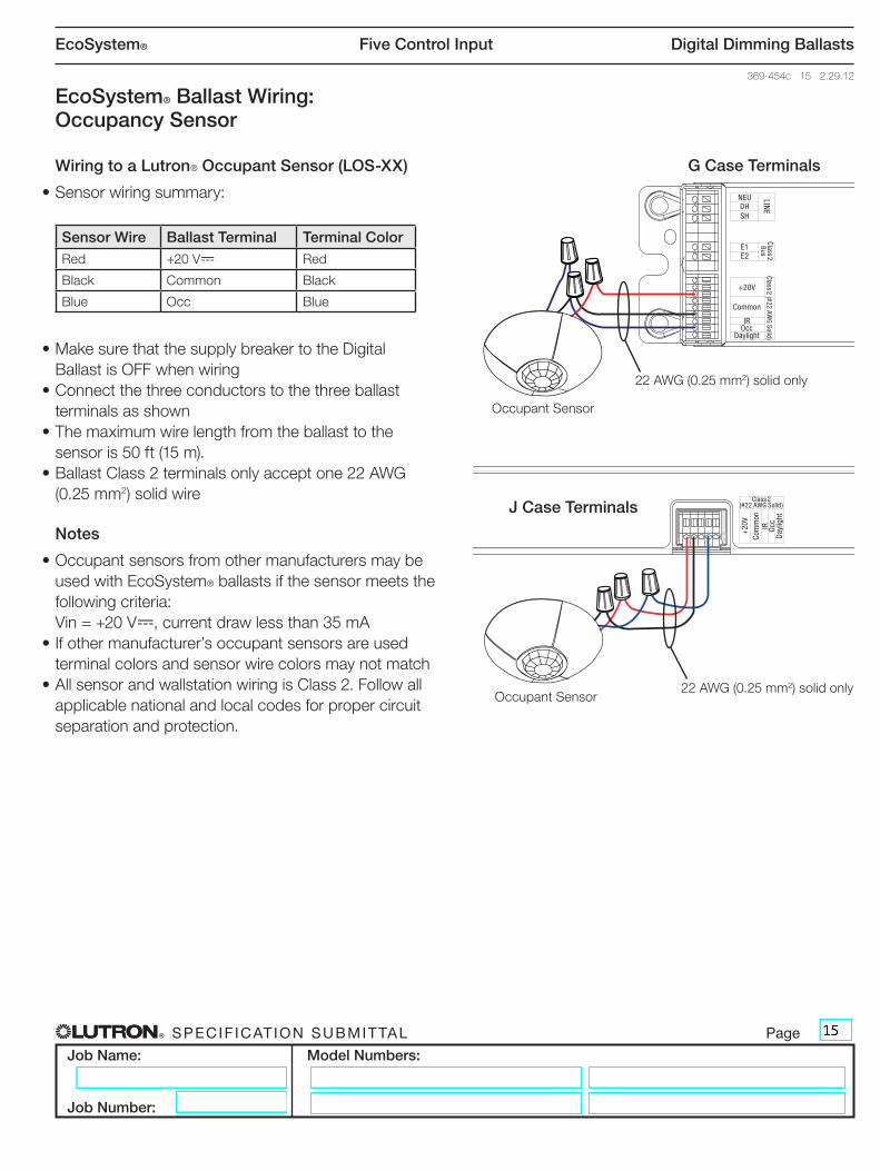
EcoSystem® Ballast Wiring: Occupancy Sensor
Wiring to a Lutron® Occupant Sensor (LOS-XX)
•Sensorwiringsummary:
Sensor Wire Ballast Terminal Terminal ColorRed +20V- Red
Black Common Black
Blue Occ Blue
•MakesurethatthesupplybreakertotheDigital BallastisOFFwhenwiring
•Connectthethreeconductorstothethreeballastterminals as shown
•Themaximumwirelengthfromtheballasttothesensor is 50 ft (15 m).
•BallastClass2terminalsonlyacceptone22AWG(0.25 mm2) solid wire
Notes
•Occupantsensorsfromothermanufacturersmaybeused with EcoSystem® ballasts if the sensor meets the followingcriteria:Vin=+20V-,currentdrawlessthan35mA
•Ifothermanufacturer’soccupantsensorsareusedterminal colors and sensor wire colors may not match
•AllsensorandwallstationwiringisClass2.Followallapplicable national and local codes for proper circuit separation and protection.
J Case Terminals
22AWG(0.25 mm2) solid only
OccupantSensor22AWG(0.25 mm2) solid only
G Case Terminals
OccupantSensor
NEUDHSH
LINE
+20V
Common
IROcc
Daylight
Class 2 (#22 AWG Solid)
Class 2 BusE1
E2
+20
VCo
mm
onIR Occ
Day
light
Class 2 (#22 AWG Solid)
® Specif icat ion Submittal page
Job Name:
Job Number:
Model Numbers:
EcoSystem® Five Control Input Digital Dimming Ballasts
369-454c 16 2.29.12
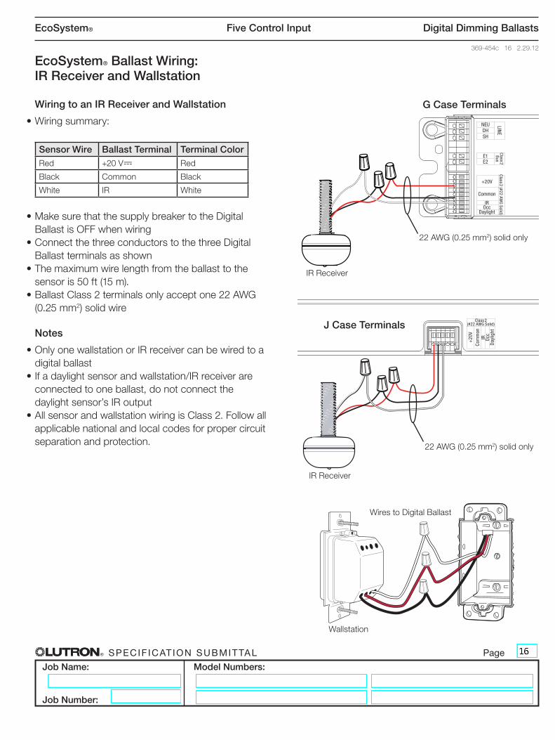
EcoSystem® Ballast Wiring: IR Receiver and Wallstation
Wiring to an IR Receiver and Wallstation
•Wiringsummary:
Sensor Wire Ballast Terminal Terminal ColorRed +20V- Red
Black Common Black
White IR White
•MakesurethatthesupplybreakertotheDigital BallastisOFFwhenwiring
•ConnectthethreeconductorstothethreeDigital Ballast terminals as shown
•Themaximumwirelengthfromtheballasttothesensor is 50 ft (15 m).
•BallastClass2terminalsonlyacceptone22AWG(0.25 mm2) solid wire
Notes
•OnlyonewallstationorIRreceivercanbewiredtoadigital ballast
•Ifadaylightsensorandwallstation/IRreceiverareconnected to one ballast, do not connect the daylightsensor’sIRoutput
•AllsensorandwallstationwiringisClass2.Followallapplicable national and local codes for proper circuit separation and protection.
22AWG(0.25 mm2) solid only
G Case Terminals
IRReceiver
J Case Terminals
22AWG(0.25 mm2) solid only
IRReceiver
Wallstation
WirestoDigitalBallast
NEUDHSH
LINE
+20V
Common
IROcc
Daylight
Class 2 (#22 AWG Solid)
Class 2 BusE1
E2
+20
VCo
mm
onIR Occ
Day
light
Class 2 (#22 AWG Solid)

® Specif icat ion Submittal page
Job Name:
Job Number:
Model Numbers:
EcoSystem® Five Control Input Digital Dimming Ballasts
369-454c 17 2.29.12
EcoSystem® Ballast Wiring: Multiple Devices
Multiple Sensors with One Ballast
•EcoSystem® ballasts accept wiring for one daylight sensorinput,oneoccupantsensorinputandoneIRinput(wallstationorIRreceiver)
•EcoSystem®daylightsensorshaveIRoutputsthat allow the device to operate as a programming port. Inapplicationswhereadaylightsensorand wallstation are wired to the same ballast, do not connect the white wire of the daylight sensor to theballast.Thewallstationoperatesasthe programmingportthroughitsintegralIRreceiver
•Usethechartbelowasaguideforwiringmultipledevices to a ballast
How to Use the Chart
Connectasensortoaballastfromthe“Devices”column(inbold).Alongtheselecteddevicerow,are“Y’s”and“N’s”.Wherea“Y”isplaced,thedevice at the top of that column can also be connected to the same ballast.An“N”indicatesnoconnectionallowed.
Devices Daylight sensor
(with IR)
Occupant sensor
Wallstation or
IR receiver
Daylight Sensor (no IR)
Daylight sensor(withIR) Y N N
Occupantsensor Y Y Y
WallstationorIRReceiver N Y Y
Daylight sensor(noIR) N Y Y
Example: When a Daylight Sensor with IR is connected to a ballast, then only an occupancy sensor can be added for the system to properly function.
J Case Terminals
+20
VCo
mm
onIR Occ
Day
light
Class 2 (#22 AWG Solid)

® Specif icat ion Submittal page
Job Name:
Job Number:
Model Numbers:
EcoSystem® Five Control Input Digital Dimming Ballasts
369-454c 18 2.29.12
EcoSystem® Ballast Wiring: Line Voltage Dimmers
EcoSystem® Ballasts and 3-wire dimmers
•Lutron®3-wiredimmersonlycontroltheballastthey are wired to; EcoSystem® does not support groupingof3-wirecontrolinput.
3-Wire Control Wiring
•MakesurethatthesupplybreakertotheDigital BallastisOFFwhenwiring.
•Wireasshown
Line input Connects toHot DimmerBlackWire
Neutral DimmerWhiteWire
Dimmer wire Connects toYellow BallastOrange(DH)
Red BallastBlack(HOT)
White BallastWhite(NEU)
Green EarthGround
•EcoSystem®ballastlinevoltageand3-wireinput terminalsonlyacceptone18to16AWG (0.75to1.5mm2) solid wire.
Emergency and 3-wire
•EcoSystem® ballasts controlled by a wallbox dimmer should not be used for emergency/egress lighting unless an external emergency ballast is used in the fixture.SeeLutronApplicationNote#50.
•EcoSystem® ballasts may be used for emergency/egresslightingwhencontrolledbyaLutron® dimmingpanel(GP);wherethepanelisadedicated emergency panel.
Notice
3-Wirecontrolturnsoffdigitalballastswhenthecontrolisintheoffposition.Thedigitalballastinputs(daylight sensor, wallstation, occupant sensor, and IRreceiver)willnotfunctionwhenthedigitalballastis turned off
LUTRON
3-WireDimmer Green
Ground
Red
Yellow
White
Neutral
Hot/Black
White
Orang
e
Black
NEUDH
HOT
LINE
Class 2 Bus
E1E2
LINE
Class 2 BusE1
E2
NEUDH
HOT

® Specif icat ion Submittal page
Job Name:
Job Number:
Model Numbers:
EcoSystem® Five Control Input Digital Dimming Ballasts
369-454c 19 2.29.12
Ballast/Socket Leads
Leadlengthsfromballasttosocketmustnotexceed7ft(2m)forlinearlamps(T5,T5HO,T8).Leadlengthsmustnotexceed3ft(1m)forT5twintubelamps.
Lamp Sockets
LampsocketsasperIEC60400arerequiredtoensurepositivelamp-pintosocketcontact.
Mounting for T5 and T5HO Lamps
Mountlamps3/8in±1/8in(9.5±3.2mm)awayfrom the grounded metal surface.
Mounting for T8 & T5 Twin Tube Lamps
Mountlamps1/2in±1/4in(13mm±6mm)awayfrom the grounded metal surface.
Havingalamptooclosetothegroundedmetalwillreducelamplife.Havingafluorescentlamptoofarawayfromthegroundedmetalwillmakethelampflickerornotturnonatall.
Lamp Seasoning Requirements
Some fluorescent lamp manufacturers recommend that new fluorescent lamps be operated at full output(“seasoned”)beforetheycanbedimmed, to render lamp impurities inert, ensuring proper dimming performance and average rated lamp life. Pleasecontactyourlampmanufacturerforseasoningrequirements.
Further Information
Forfurtherinformationpleasevisit www.lutron.com/ecosystemorcontactour24-hourTechnicalSupportCenterat1-800-523-9466.
Attention Electricians and Fixture Manufacturers