Embed Size (px)
Citation preview
Energy Conservation Environment Process Efficiency| | www.forbesmarshall.com
Forbes Marshall Forbes Marshall Arca Forbes Marshall Codel J N Marshall Krohne Marshall Spirax Marshall Forbes Vyncke
EcotrolOperational economy with optimum control
®

®
* Refer Page No. 24 for Kv Values
01 PR BAL PISTON RING02 PR BAL Q RING03 DOUBLE GUIDE04 PR BAL SPECIAL

10 Commandments to Develop the New Control Valve ECOTROL®
1010
3311 22Reliability
On highest priority. This product is based on our experience of over 60 years
Develop what the Customer Requires
For this reason we asked him, evaluated his feedback and incorporated the result into the design of this control valve.
Progress
By deve lop ing a d ig i ta l positioner of the second generation with the option of bidirectional communication.
5544 66Flexibility
Invention of a compact, pipeless a n d v i b r a t i o n r e s i s t a n t positioner mounting which guarantees quick assembly and high reliability for all actuator functions.
Cost of Ownership
Decrease of operating and maintenance cost, (in addition). The SWS-seat (quick changeable trim combination) for example offers the option of a double-side use by reversing the seat r i n g ( r e s u l t s f r o m t h i s procedure).
EnvironmentalAwareness
By a stem sealing that meets today's requi rements by providing a corrosion resistant stuffing box area.
77 9988Efficiency
Double use of auxiliary energy by using the tried and tested p n e u m a t i c m u l t i - s p r i n g diaphragm actuator with the option of permanent spring case ventilation.
Universal
Design according to ANSI with standardised trims.
Precision
A v o i d i n g m i s a l i g n m e n t between actuator and valve guiding by applying of up-to-date CNC manufacturing techniques.
Control of the "Magic Triangle"
Shortening the delivery time, minimising the cost with at the same time higher technical value, improvements and quality.
The result is called
A new control valve without any compromise. Perfect with regard to quality, efficiency, weight and ease of maintenance-a valve which is unique.
ECOTROL
For over six decades, Forbes Marshall has been building steam engineering and control instrumentation solutions that work for process industry. Today we have evolved into a leader in process efficiency and energy conservation through technology tie-ups and focused investments in manufacturing and research. Our joint ventures with the world's leading names enable us to deliver quality solutions in 14 countries. Forbes Marshall is unique in having extensive expertise in both steam and control instrumentation. The dual expertise has allowed us to engineer industry specific systems that focus on energy efficiency and utilities management for sectors as diverse as textiles, food processing, paper, power and chemicals.
Our teams are peopled by some of the finest engineers in the land. These highly trained professionals have developed innovative solutions and saved millions of rupees in process costs for our clients. Our business practices and processes have combined into a singular philosophy of being trusted partners who provide innovative solutions. It's a philosophy we are proud to live up to.
For decades, we have partnered with some of the best names in the control instrumentation industry such as Arca, Codel, Krohne and Shinkawa, to develop, design and supply innovative solutions for measurement and monitoring of process parameters. With a combination of specialist knowledge and the latest technology, we provide products and solutions to achieve optimum efficiency. Our products are a unique combination of hardware and software that make them reliable and accurate.
®

The valve series FORBES MARSHALL ARCA-ECOTROL is a robust, compact and lightweight control valve with a pneumatically operated, easy field reversible multi-spring diaphragm actuator FORBES MARSHALL ARCAPAQ 812 and a sturdy, pipeless and vibration-resistant mounted digital positioner. Optional, the actuator can be equipped with a fully enclosed emergency handwheel which is in compliance with general safety precautions (1). The highlight of this valve series is the FORBES MARSHALL ARCA-double-life (quick-changeable trim combination) with the option of a double-side use by reversing the seat ring (10). Because of its simple geometry the valve seat can be economically produced in different materials like steel, hardened and stellited steel, ceramic, Tungsten carbide, etc., with or without soft sealing. In comparison to conventional designs the speciality of the ECOTROL’s soft sealing is, that the PTFE-element is flexibly supported by an additional Elastomer O-Ring. Both sealing elements are located in the seat ring and not as usual in the valve plug. The additional metal-to-metal sealing of plug and seat ring ensures that the PTFE-disc suitable for double side use is not plastically deformed by excessive loads.
The remarkable difference between the common screwed-in seat ring and this unique quick-change(able) trim combination, shown in the figures hereinafter, is because of the principle of retaining and sealing the seat ring in the valve body. With a screwed-in seat ring the sealing between seat and valve body is provided by the metal-to-metal contact of two conical faces.
The conical counter-face in the valve body has a slightly different angle so that there is only a theoretical circumferential line contact. The required torque to screw-in the seat ring is individually different depending on the construction and the operating conditions. With the FORBES MARSHALL ARCA ECOTROL valve series the seat sealing is done purely axial and achieved by the method of initial compression.
The compression of the sealing elements (6, 11) is limited by the precisely sized recess in the body for containment of the flat gasket. This limits the gasket’s compressive loading and guarantees a perfect alignment between the sealing surfaces of plug and seat ring.
The self-aligning seat ring (10) is held by the retaining cage (9). The tightness is achieved by transferring a portion of the bonnet-to-body bolting force via the retaining cage to the seat ring. The valve body (12), retaining cage, and seat ring are manufactured on special CNC-machining centres to meet the stringent tolerance of each part. This guarantees the required compression of the sealing elements. Excellent stem guiding is performed by two special guide bushings (4, 8) located as far as possible from each other.
ECOTROL
Series 8C1
8C6N6H
®
®The Profitable Solution: ECOTROL
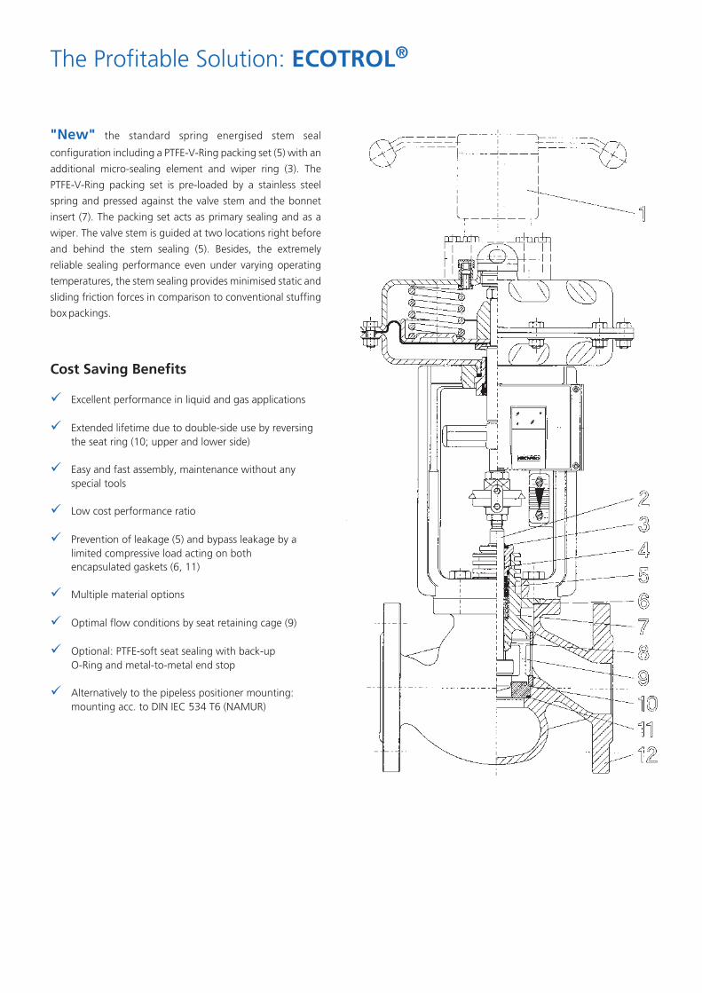
"New" the standard spring energised stem seal configuration including a PTFE-V-Ring packing set (5) with an additional micro-sealing element and wiper ring (3). The PTFE-V-Ring packing set is pre-loaded by a stainless steel spring and pressed against the valve stem and the bonnet insert (7). The packing set acts as primary sealing and as a wiper. The valve stem is guided at two locations right before and behind the stem sealing (5). Besides, the extremely reliable sealing performance even under varying operating temperatures, the stem sealing provides minimised static and sliding friction forces in comparison to conventional stuffing box packings.
Cost Saving Benefits
Excellent performance in liquid and gas applications
Extended lifetime due to double-side use by reversing the seat ring (10; upper and lower side)
Easy and fast assembly, maintenance without any special tools
Low cost performance ratio
Prevention of leakage (5) and bypass leakage by a limited compressive load acting on both encapsulated gaskets (6, 11)
Multiple material options
Optimal flow conditions by seat retaining cage (9)
Optional: PTFE-soft seat sealing with back-up O-Ring and metal-to-metal end stop
Alternatively to the pipeless positioner mounting: mounting acc. to DIN IEC 534 T6 (NAMUR)
¸̧¸¸̧¸̧¸¸

Depending on the operating conditions, the stem sealing consists of a special sealing configuration to ensure lowest fugitive emission and minimised friction. The stem and the packing bore provide a super finished surface manufactured by the so-called roller burnishing process. This process compresses the surface and increases its hardness.
Stem sealing
The bottom base ring in the V-Ring set acts as a wiper and just allows a small amount of fluid to reach the micro-sealing element. This final sealing element is made of a special Elastomer material. Its distance from the top wiper ring is equal to the maximum stroke length. While the valve remains in open position, dirt or any kind of stain may accumulate on the stem part right above the top wiper ring. When the stem moves to the closed position some stain may pass the wiper ring, however, it will never approach the micro-sealing element and cause this element to fail.
The Standard Maintenance-free PTFE-V-Ring Packing with a Micro-Sealing Element
To guarantee the sealing performance at very low pressures, the PTFE-V-ring packing set is preloaded by a corrosion resistant spring. In normal operation the sealing lips are pressed against the stem and the packing bore relative to the fluid pressure (pressure energised). To resist the internal pressure resulting from alternating operating conditions the V-Ring set is made of different compounds. The outer packing consists of PTFE with a graphite filling and the centre ring is made of pure PTFE.
risk of an unequal compression of each packing. In such case the upper rings are compressed more than the lower ones due to frictional forces. This leads to an unfavourable non-homogeneous compression of each ring. Since only the top packing seals tightly, it comes to an early leakage in service and the torque demand also increases. As a consequence, the torque transferred from the screwed stuffing box must be applied with care, so that the packing sealing becomes effective, while the hysteresis does not become too high.
Graphite Stuffing Box
A reliable and safe packing assembly requires a homogeneous compression of the entire set of graphite packings. The screwed stuffing box transfers the compressive load to each packing in the stuffing box. This is similar to the hydro- static principle of pressure distribution in a fluid. To achieve a steady homogeneous compression of all packings, the lower rings must be compressed more than the upper ones during assembly. To realise this, the patented ARCA-OPTIPRESS pre-loading device, activated by the actuator, is recommended.
If the packing loading is simply done by tightening the screwed stuffing box there is the
Bellows Seal Bonnet
Hermetically sealing bellows are available for process fluids when no stem leakage can be tolerated (e.g. toxic fluids). The pressure-proof and elastic stainless steel bellows is tightly seal-welded to the valve stem and the upper adapter ring. For safety reasons the construction includes a standard stem sealing as back-up in case of a bellows failure. Between bellows and packing a tapped hole with a plug screw is optionally supplied, either to be used as leak detection, bleed-off, or for inserting a blocking gas.
The voluminous bellows housing provides a reasonable flow
velocity around the bellows and, therefore, reduces the susceptibility of the bellows against crystallising fluids or polymers. The design is equipped with a built-in twist protection that safely keeps the torque caused either by fluid forces or by improper handling away from the bellows, a guarantee against sudden bellows failure and the resulting shutdown and repair costs. Of course, the FORBES MARSHALL ARCA bellows sealing is in full compliance IS0 15848

Stem sealing
The bushing with a straight through bore allows superfinishing of the surface which ensures perfect sealing between packing or sealing ring and bushing. The stainless steel bushing avoids or minimises any corrosion and spoiling in the vicinity of the sealing.
Wear Resistant Bushing
To prevent galvanic corrosion between the bonnet stuffing box (carbon steel) and the packing (graphite), all bonnets of valves larger than DN 50 (NPS 2") offer a special treated stainless steel bushing. For valves equal or less than DN 50, the bonnet is always made of stainless steel.
Bonnet Extension for Cryogenic Service
The cross sectional drawing shows the principle design of the newly developed
®ECOTROL control valve for cryogenic service. The valve plug and stem extension are double guided. The bottom guiding is located right below the valve seat. This guarantees a reliable sealing performance, a vibration free guiding of the plug, and an easy replacement of the guide bushing. Every part that is subject to wear can be individually replaced. The seat is axially restrained by the retaining cage and the top flange.
The bonnet extension prevents icing of the packing area. The thin walls of the insulation column and of the stem extension allow only a very low conductive heat flow. In addition, the stem extension pipe is filled with Perlite to reduce convective heat loss to a minimum. The bonnet extension length is based on customer requirements.
All cryogenic valves, apart from ARCA's standard valves, are assembled in a clean-room environment. Here, the valves undergo a thorough cleaning process in a subsonic bath followed by a complete dehydration in an air circulating dryer.
PED Top Flange Design (8C1)
To be in compliance with the European Pressure Equipment Directive (PED) the valve's top flange and actuator yoke (material: austenitic stainless steel) are made of two individual parts. The top flange is permanently attached to the body and untying is unnecessary for dismounting the actuator.

Trim Styles
Parabolic Plug (Standard)
Metal-seated quick-changeable trim combination.
Insensitive to impurities with low cavitation design.
Fast and easy to produce due to its rotational symmetry.
Parabolic Plug with Soft Sealing and Secondary Metal-to-Metal Sealing
Soft-seated quick-changeable tr im combination The PTFE-soft sealing (for unrestricted use on both sides) is flexibly supported by an additional Elastomer 0-Ring. The additional metal-to- metal sealing of plug and seat ring ensures that the PTFE-disc is not plastically deformed by excessive loads when the plug reaches its final closed position.
Parabolic Plug Double-Guided
Metal-seated quick-changeable trim combination with top and bottom guiding.
This double guiding construction stabilizes stem and plug over the full travel range. Therefore, it is recommended for high pressure drop applications.
The additional guiding is located right
below the seat ring and can be easily replaced.
Most conventional body designs with top and bottom guided trim have a bolted bottom flange which requires an extra body gasket plus the risk of additional external leakage.
The ECOTROL one-piece body design eliminates this problem and ensures optimum tightness.
Perforated Plug/Perforated Low Noise Cage
Metal-seated quick-changeable trim combination. Particularly effective for liquids and compressible fluids at high pressure drop ratios. Liquid flow can cause erosion by cavitation. The flow, directed through the holes of the trim, is divided into numerous jets of cavitating liquid.
In the centre of the cage the jets impact and the vapour bubbles collapse. Here, they do not cause any damage to the valve internals and the noise level is also considerably reduced. For more noise abatement a perforated low noise cage is available for all trim designs.
Balanced Trim
Valves with balanced trims require much lower control forces than valves without balancing. As sealing elements we offer:
• metallic piston rings • Elastomer Quadrings with PTFE support• pure graphite
Trim Styles/Precautions against Wear and Tear
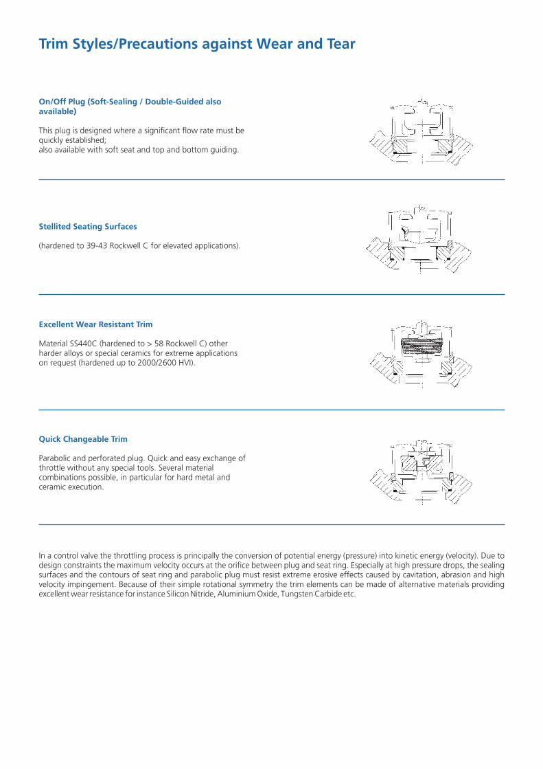
On/Off Plug (Soft-Sealing / Double-Guided also available)
This plug is designed where a significant flow rate must be quickly established; also available with soft seat and top and bottom guiding.
Stellited Seating Surfaces
(hardened to 39-43 Rockwell C for elevated applications).
Excellent Wear Resistant Trim
Material SS440C (hardened to > 58 Rockwell C) other harder alloys or special ceramics for extreme applications on request (hardened up to 2000/2600 HVI).
Quick Changeable Trim
Parabolic and perforated plug. Quick and easy exchange of throttle without any special tools. Several material combinations possible, in particular for hard metal and ceramic execution.
In a control valve the throttling process is principally the conversion of potential energy (pressure) into kinetic energy (velocity). Due to design constraints the maximum velocity occurs at the orifice between plug and seat ring. Especially at high pressure drops, the sealing surfaces and the contours of seat ring and parabolic plug must resist extreme erosive effects caused by cavitation, abrasion and high velocity impingement. Because of their simple rotational symmetry the trim elements can be made of alternative materials providing excellent wear resistance for instance Silicon Nitride, Aluminium Oxide, Tungsten Carbide etc.

10
ASME 16.34
ASME B 16.34 150/300
Temperature
00 C 0100 C 0200 C 0300 C 0400 C 0500 C
60,0
50,0
40,0
30,0
20,0
10,0
Pres
sure
in b
ar
0,0
100,0
0,0
50,0
Temperature
ASME B 16.34 600/900/1500
Pres
sure
in b
ar
00 C 0100 C 0200 C 0300 C 0400 C 0500 C
150,0
200,0
250,0
300,0
WC6
CF8M
WCB
Pressure-Temperature Diagram

Sealing Ring Packing Micro O-Ring Wiper TemperatureType (Pos.A) Sealing (Pos.C) Ring of Fluid Bonnet Type Comments
(Pos.B) (Pos.D)maintenance PTFE-Ring EPDMfree, double (VITON) (VITON) (200)ºC with SS
guiding springReinforced
readjustable Graphite/ - - NBR -20~400ºC Standard / RegularInconel (VITON) Cooling fins ServiceBraided/ High
readjustable Pure Graphite - - VITON -20~530ºC Standard / Temperatureor Pure Cooling fins Service
GraphiteBraided/
readjustable Pure Graphite - - NBR -196~20ºC Bonnet Cryogenicor Pure Extension Service
GraphiteBraided Standard / Cryogenic
readjustable Graphite/PTH - - NBR -196~200ºC Bonnet ServiceExtension
bellows seal- PTFE V-Ring Live Loadeding with safe- Bellows in EPDM EPDM NBR -100~200ºC Bellows with SSty double 316 or (VITON) Sealing springsealing Hastelloy Cbellows high and low
sealing with Braided - - NBR -196~400ºC Bellows temperaturesafety double Graphite/PTFE - - Sealing service
sealing
EPDM NBR -25~180 Standard Live Loaded
Technical Data and Materials
1) Only from ≥ DN50 ≥ kvs 40
Parabolic PlugMaterial Parabolic Plug P1 Perforated Plug Seat Seat Sealing Temperature of FluidCode No. Integrated L1 Type
1) Double Guiding1 SS316 - - SS316 metal-to-metal acc. to stem sealing2 - SS316 SS316 nitrided SS316 metal-to-metal acc. to stem sealing3 - - SS440C nitrided SS410 metal-to-metal acc. to stem sealing4 SS440C hardened SS440C hardened SS440C hardened SS440C hardened metal-to-metal acc. to stem sealing5 1.4922 1.4922 nitrided 1.4922 nitrided 1.4922 metal-to-metal acc. to stem sealing6 SS316 - - SS316 PTFE/EPDM -50 ~140ºC7 SS316 SS316 PTFE -196 ~180ºC
ECOTROL Standard Trims
Permissible Temperature Range for Packings
Temperature dueto convection heat loss
Temperature of fluid
1) also available with self-readjustable stuffing box packing
ECOTROL General DataNominal Size Ω” - 16”Pressure Rating ANSI 150-1500Material of Body ASTM for temperaturesA 216 WCB -28ºC to 427ºCA 351 CF8M -196ºC to 400ºCA 351 CF8 -196ºC to 400ºCA 352 LCB -50ºC to 400ºCA 217 WC6 -28ºC to 550ºCA 217 WC9 -28ºC to 550ºCMaterial of Bonnet £ DN 50 in material CF8M (SS316) / CF8 (SS304)≥ DN 80 in material same as body but with sealing bushing in SS316Characteristics of Plug Standard: Equal percentage and Linear
Optional: Modified LinearRangeability 50:1, 40:1Double Guiding Optional: integradted double guiding available 1Ω - 16”, Kvs>40Seat Leakage Metal-to-Metal: Leakage Class IV (<0.01%kvs); optional leakage rate class VElastometer-to-Metal: Class VIBellows Sealing 1. SS316 weldless double layer or optional in Available for ANSI 150 and ANSI 300,2. Hastealloy C / Monel other pressure classes on requestHeating Jacket Connections Ω” or 1” ANSI 300 socket screwed or flanged and other on request
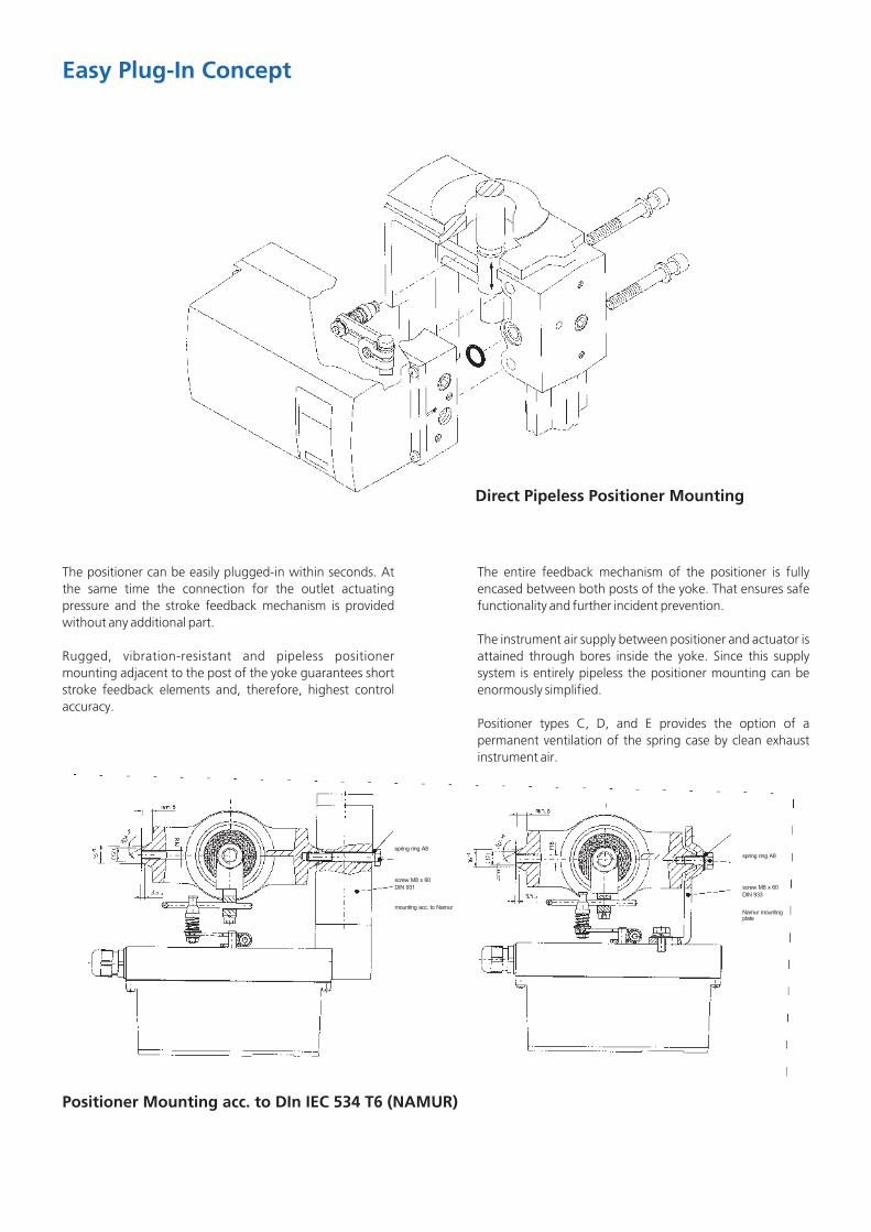
The positioner can be easily plugged-in within seconds. At the same time the connection for the outlet actuating pressure and the stroke feedback mechanism is provided without any additional part.
Rugged, vibration-resistant and pipeless positioner mounting adjacent to the post of the yoke guarantees short stroke feedback elements and, therefore, highest control accuracy.
Easy Plug-In Concept
The entire feedback mechanism of the positioner is fully encased between both posts of the yoke. That ensures safe functionality and further incident prevention.
The instrument air supply between positioner and actuator is attained through bores inside the yoke. Since this supply system is entirely pipeless the positioner mounting can be enormously simplified.
Positioner types C, D, and E provides the option of a permanent ventilation of the spring case by clean exhaust instrument air.
Direct Pipeless Positioner Mounting
Positioner Mounting acc. to DIn IEC 534 T6 (NAMUR)

ARCA series 812 multi-spring actuators support the standardised positioner mounting per VDI/VDE 3847. This interface allows the easy exchange of positioners and solenoid valves made by different manufacturers, without losing the advantages of integrated mounting such as: ?high stability even in extreme stress situations caused by vibration and shock?the pipeless supply of control air to the actuator's diaphragm chamber for fail-to-close action (for pipeless fail-to- open action
choose actuator type C). ?direct mounting of solenoid valves per VDI/VDE 3845 (1998).
As special option, the interface is also available with separate block valves for air supply, positioner outlet and solenoid valve outlet. On demand, the valve may be locked, and the positioner / solenoid valve can be exchanged without impact or disturbance to the process itself.
Mounting of Positioner acc. to VD/NDE 3847

Diaphragm Actuator Series 812
Pneumatically operated multi-spring diaphragm actuator of the new generation. The actuator is easily field reversible without the need of disassembly. The instrument air supply between positioner and actuator is attained through bores inside the yoke providing more reliability in comparison to conventional designs. This method ensures a safe air supply to the actuator and simplifies enormously the positioner mounting. Furthermore, the combination with the positioner type 824 or the digital positioner of the second generation type 827 provides the option of a permanent ventilation of the spring case by clean exhaust instrument air.
During operation there is a minimal overpressure against atmosphere on the rear of the diaphragm plate (spr ing chamber). This guarantees that during stroke movement no ambient air can be sucked into the spring chamber. This protects the essential inner parts against aggressive atmosphere (like sea air).
Air to open
Size Diaphragm TYPE No. of Stroke Min. Air Thrust (kN)2area (cm) springs (mm)* press. depending on air pressure
2.0 3.0 4.0 5.0 6.0bar bar bar bar bar
MFI-20 812.25(6) 3 20 1.5 1.6 4.8 8.0 11.2 14.46 3.0 3.2 6.4 9.6
320 3 1.5 1.6 4.8 8.0 11.2 14.4MFI-30 812.23 6 3.0 3.2 6.4 9.63 1.5 3.6 10.8 18.0 25.2 32.46 30 3.0 7.2 14.4 21.6
MFIII-30 812.33 9 3.7 2.2 9.4 16.612 4.4 4.3 11.5
720 3 1.5 3.6 10.8 18 25.2 32.46 3.0 7.2 14.4 21.6
MFIII-60 812.34 9 60 3.6 2.9 10.1 17.312 4.3 5.0 12.2
Air to close
* 8C DN15 (1/2") – DN50 (2”) parabolic plug (P1) - valve stroke 16 mmMultihole cage (L1) - valve stroke 20 mm
Size Diaphragm Type No. of Stroke Air Pressure Range Thrust Force2area (cm) springs from(bar) to(bar) (kN)
MFI-20 812.25(6) 3 0.8 1.5 2.46 1.5 3.0 4.8
MFI-30 320 3 20 1.0 1.5 3.3(pre-loading) 812.23 6 2.0 3.0 6.5
MFI-30 3 0.8 1.5 2.46 1.5 3.0 4.83 0.7 1.5 5.0
MFIII-30 812.33 6 1.5 3.0 10.09 30 1.8 3.7 13.0
12 2.2 4.4 16.03 1.1 1.5 8.0
MFIII-60 720 6 2.2 3.0 16.0(pre-loading) 9 2.7 3.6 19.0
12 3.1 4.3 23.0812.34 3 0.7 1.5 5.0
MFIII-60 6 60 1.4 3.0 10.09 1.7 3.6 12.0
12 2.0 4.3 14.0
Description

Diaphragm Actuator Series 811 and MA
*) at 100% **) at 0%
Air to closeSize Diaphragm Type No. of Stroke Min. Air
2area (cm) springs (mm) press.(bar) 1.4 bar 2.0 bar 3.0 bar 4.0 bar 5.0 bar 6.0 bar
UV-60 1440 811.41 1 60 0.8 9.7 18.4 32.8 43.6 65.3 76.2
UV-100 811.43 1 100 0.8 7.9 16.5 30.9 41.7 63.3 74.1
MA3.60A 2G 2 0.8 12.0 23.0 41.5 60.0 78.5 97.025 mm 1853 4G 4 1.6 - 9.0 27.5 46.6 64.5 83..0
(pre-loading) (2185)** 6G 6 60 2.4 - - 14.0 32.5 51.0 69.58G 8 3.2 - - - 18.5 37.0 55.5
MA3.60D 2R 2 1.1 6.0 16.0 32.5 49.0 65.5 82.025 mm 1652 4R 4 2.2 - - 15.5 32.0 48.5 65.0
(pre-loading (2185)** 6R 6 100 3.3 - - - 15.0 31.5 48.08R 8 4.4 - - - - 14.5 31.0
MA3.60D 2R 2 1.3 4.5 12.0 27.5 43.5 59.0 74.55 mm 1566 4R 4 2.6 - - 8.5 24.0 40.0 55.5
(pre-loading) (2185)** 6R 6 120 3.9 - - - 5.0 20.5 36.58R 8 5.2 - - - - 1.5 17.5
Thrust force (kN)depending on Air Pressure
Air to openDiaphragm No. of Stroke Air Pressure RangeThrust
2Size area (cm) Type springs (mm) From (bar) to (bar) Force
UV-60 811.41 1 60 0.1 1.8 14.4
UV-100 1440 811.43 1 100 0.1 1.4 8.4
UV-120 811.47 1 120 0.0 3.0 8.6
MA3.60A 2G 2 0.6 0.9 10.125 mm 2047 4G 4 60 1.1 1.9 20.2
(pre-loading) (1715)* 6G 6 1.7 2.8 30.38G 8 2.3 3.7 40.4
MA3.60D 2R 2 0.5 1.3 8.725 mm 2047 4R 4 100 1.0 2.6 17.4
(pre-loading) (1715)* 6R 6 1.5 3.9 26.18R 8 2.0 5.3 34.8
MA3.60D 2R 2 0.3 1.3 6.65 mm 2157 4R 4 120 0.7 2.6 13.2
(pre-loading) (1544)* 6R 6 1.0 3.9 19.78R 8 1.4 5.3 26.3
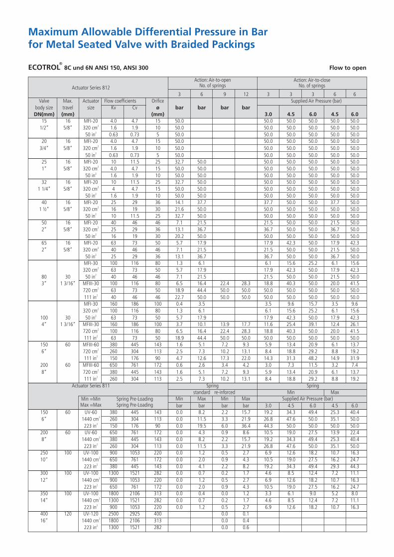
Maximum Allowable Differential Pressure in Barfor Metal Seated Valve with Braided Packings
Actuator Series 8123 6 9 12 3 3 3 6 6
Valve Max. Actuator Flow coefficients Orifice Supplied Air Pressure (bar)body size travel size Kv Cv ø bar bar bar barDN(mm) (mm) (mm) 3.0 4.5 6.0 4.5 6.0
15 16 MFI-20 4.0 4.7 15 50.0 50.0 50.0 50.0 50.0 50.021/2” 5/8” 320 cm 1.6 1.9 10 50.0 50.0 50.0 50.0 50.0 50.0
250 in 0.63 0.73 5 50.0 50.0 50.0 50.0 50.0 50.020 16 MFI-20 4.0 4.7 15 50.0 50.0 50.0 50.0 50.0 50.0
23/4” 5/8” 320 cm 1.6 1.9 10 50.0 50.0 50.0 50.0 50.0 50.0250 in 0.63 0.73 5 50.0 50.0 50.0 50.0 50.0 50.0
25 16 MFI-20 10 11.5 25 32.7 50.0 50.0 50.0 50.0 50.0 50.021” 5/8” 320 cm 4.0 4.7 15 50.0 50.0 50.0 50.0 50.0 50.0 50.0
250 in 1.6 1.9 10 50.0 50.0 50.0 50.0 50.0 50.0 50.032 16 MFI-20 10 11.5 25 32.7 50.0 50.0 50.0 50.0 50.0 50.0
21 1/4” 5/8” 320 cm 4 4.7 15 50.0 50.0 50.0 50.0 50.0 50.0 50.0250 in 1.6 1.9 10 50.0 50.0 50.0 50.0 50.0 50.0 50.0
40 16 MFI-20 25 29 36 14.1 37.7 37.7 50.0 50.0 37.7 50.021 Ω” 5/8” 320 cm 16 19 30 21.6 50.0 50.0 50.0 50.0 50.0 50.0
250 in 10 11.5 25 32.7 50.0 50.0 50.0 50.0 50.0 50.050 16 MFI-20 40 46 46 7.1 21.5 21.5 50.0 50.0 21.5 50.0
22” 5/8” 320 cm 25 29 36 13.1 36.7 36.7 50.0 50.0 36.7 50.0250 in 16 19 30 20.2 50.0 50.0 50.0 50.0 50.0 50.0
65 16 MFI-20 63 73 50 5.7 17.9 17.9 42.3 50.0 17.9 42.322” 5/8” 320 cm 40 46 46 7.1 21.5 21.5 50.0 50.0 21.5 50.0
250 in 25 29 36 13.1 36.7 36.7 50.0 50.0 36.7 50.0MFI-30 100 116 80 1.3 6.1 6.1 15.6 25.2 6.1 15.6
2320 cm 63 73 50 5.7 17.9 17.9 42.3 50.0 17.9 42.3280 30 50 in 40 46 46 7.1 21.5 21.5 50.0 50.0 21.5 50.0
3” 1 3/16” MFIII-30 100 116 80 6.5 16.4 22.4 28.3 18.8 40.3 50.0 20.0 41.52720 cm 63 73 50 18.9 44.4 50.0 50.0 50.0 50.0 50.0 50.0 50.0
2111 in 40 46 46 22.7 50.0 50.0 50.0 50.0 50.0 50.0 50.0 50.0MFI-30 160 186 100 0.4 3.5 3.5 9.6 15.7 3.5 9.6
2320 cm 100 116 80 1.3 6.1 6.1 15.6 25.2 6.1 15.62100 30 50 in 63 73 50 5.7 17.9 17.9 42.3 50.0 17.9 42.3
4” 1 3/16” MFIII-30 160 186 100 3.7 10.1 13.9 17.7 11.6 25.4 39.1 12.4 26.12720 cm 100 116 80 6.5 16.4 22.4 28.3 18.8 40.3 50.0 20.0 41.5
2111 in 63 73 50 18.9 44.4 50.0 50.0 50.0 50.0 50.0 50.0 50.0150 60 MFIII-60 380 445 143 1.6 5.1 7.2 9.3 5.9 13.4 20.9 6.1 13.7
26” 720 cm 260 304 113 2.5 7.3 10.2 13.1 8.4 18.8 29.2 8.8 19.22111 in 150 176 90 4.7 12.6 17.3 22.0 14.3 31.3 48.2 14.9 31.9
200 60 MFIII-60 650 761 172 0.6 2.6 3.4 4.2 3.0 7.3 11.5 3.2 7.428” 720 cm 380 445 143 1.6 5.1 7.2 9.3 5.9 13.4 20.9 6.1 13.7
2111 in 260 304 113 2.5 7.3 10.2 13.1 8.4 18.8 29.2 8.8 19.2Actuator Series 811 Spring Spring
standard re-inforced Min MaxMin Max Min Max Supplied Air Pressure (bar)Min =Min Spring Pre-Loading
Max =Max Spring Pre-Loading bar bar bar bar 3.0 4.5 6.0 4.5 6.0150 60 UV-60 380 445 143 0.0 8.2 2.2 15.7 19.2 34.3 49.4 25.3 40.4
26” 1440 cm 260 304 113 0.0 11.5 3.3 21.9 26.8 47.6 50.0 35.1 50.02223 in 150 176 90 0.0 19.5 6.0 36.4 44.3 50.0 50.0 50.0 50.0
200 60 UV-60 650 761 172 0.0 4.3 0.9 8.6 10.5 19.0 27.5 13.9 22.428” 1440 cm 380 445 143 0.0 8.2 2.2 15.7 19.2 34.3 49.4 25.3 40.4
2223 in 260 304 113 0.0 11.5 3.3 21.9 26.8 47.6 50.0 35.1 50.0250 100 UV-100 900 1053 220 0.0 1.2 0.5 2.7 6.9 12.6 18.2 10.7 16.3
210” 1440 cm 650 761 172 0.0 2.0 0.9 4.3 10.5 19.0 27.5 16.2 24.72223 in 380 445 143 0.0 4.1 2.2 8.2 19.2 34.3 49.4 29.3 44.3
300 100 UV-100 1300 1521 282 0.0 0.7 0.2 1.7 4.6 8.5 12.4 7.2 11.1212” 1440 cm 900 1053 220 0.0 1.2 0.5 2.7 6.9 12.6 18.2 10.7 16.3
2223 in 650 761 172 0.0 2.0 0.9 4.3 10.5 19.0 27.5 16.2 24.7350 100 UV-100 1800 2106 313 0.0 0.4 0.0 1.2 3.3 6.1 9.0 5.2 8.0
214” 1440 cm 1300 1521 282 0.0 0.7 0.2 1.7 4.6 8.5 12.4 7.2 11.12223 in 900 1053 220 0.0 1.2 0.5 2.7 6.9 12.6 18.2 10.7 16.3
400 120 UV-120 2500 2925 400 0.0 0.1216” 1440 cm 1800 2106 313 0.0 0.4
2223 in 1300 1521 282 0.0 0.6
ECOTROL 8C und 6N ANSI 150, ANSI 300 Flow to open
Action: Air-to-openNo. of springs
Action: Air-to-closeNo. of springs

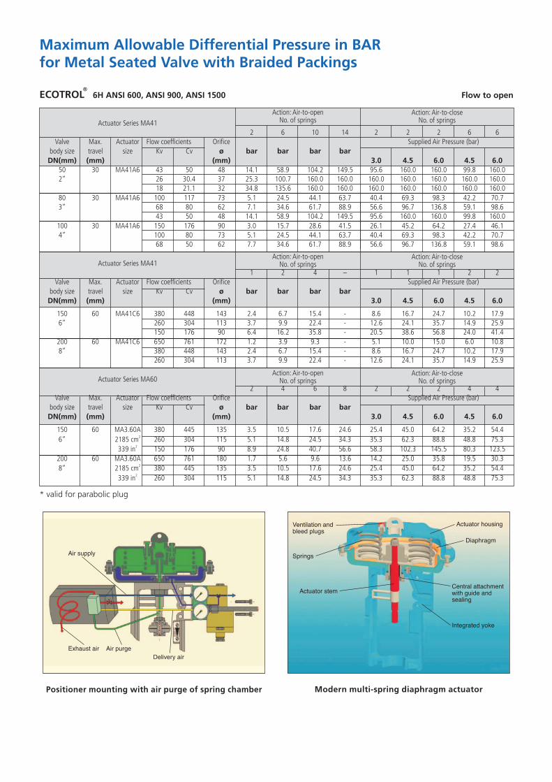
Maximum Allowable Differential Pressure in BARfor Metal Seated Valve with Braided Packing
ECOTROL 6H ANSI 600, ANSI 900, ANSI 1500 Flow to open
* valid for parabolic plug
Actuator Series 8123 6 9 12 3 3 3 6 6
Valve Max. Actuator Flow coefficients Orifice Supplied Air Pressure (bar)body size travel size Kv Cv ø bar bar bar barDN(mm) (mm) (mm) 3.0 4.5 6.0 4.5 6.0
11 12.9 24 27.0 80.1 80.1 160.0 160.0 80.1 160.0MFI-20 7 8.2 19 45.9 130.6 130.6 160.0 160.0 130.6 160.0
225 20 320 cm 4 4.7 16 67.1 160.0 160.0 160.0 160.0 160.0 160.021” 5/8” 50 in 2.5 2.9 11 150.2 160.0 160.0 160.0 160.0 160.0 160.0
1.6 1.9 9 160.0 160.0 160.0 160.0 160.0 160.0 160.040 20 MFI-20 26 30.4 37 9.5 31.8 31.8 76.4 121.1 31.8 76.4
21 Ω” 5/8” 320 cm 18 21.1 32 13.6 43.5 43.5 103.2 160.0 43.5 103.2250 in 11 12.9 24 27.0 80.1 80.1 160.0 160.0 80.1 160.0
MFI-30 43 50 48 3.6 16.8 16.8 43.8 69.9 16.8 43.42320 cm 26 30.4 37 7.6 29.9 29.9 74.6 119.2 29.9 74.6
250 in 18 21.1 32 11.2 41.0 41.0 100.7 160.0 41.0 100.750 30 MFIII-30 43 50 48 17.9 45.6 62.1 78.7 52.2 111.9 160.0 55.5 115.2
22” 5/8” 720 cm 26 30.4 37 31.8 78.3 106.2 134.1 89.5 160.0 160.0 95.0 160.02111 in 18 21.1 32 43.5 105.7 143.0 160.0 120.6 160.0 160.0 128.0 160.0
MFI-30 100 117 73 0.6 6.3 6.3 17.8 29.3 6.3 17.82320 cm 68 80 62 1.4 9.4 9.4 25.3 41.2 9.4 25.3
250 in 43 50 48 3.6 16.8 16.8 43.4 50.0 16.8 43.480 30 MFIII-30 100 117 73 6.8 18.8 25.9 33.1 21.6 47.4 73.2 23.1 48.9
23” 1 3/16” 720 cm 68 80 62 10.0 26.6 36.5 46.5 30.6 66.3 102.1 32.5 68.32111 in 43 50 48 17.9 45.6 62.1 78.7 52.2 111.9 160.0 55.5 115.2
MFI-30 150 176 90 0.0 3.8 3.8 11.3 18.8 3.8 11.32320 cm 100 117 73 0.6 6.3 6.3 17.8 29.3 6.3 17.8
250 in 68 80 62 1.4 9.4 9.4 25.3 41.2 9.4 25.3\100 30 MFIII-30 150 176 90 4.1 11.9 16.6 21.4 13.8 30.8 47.8 14.8 31.7
24” 1 3/16” 720 cm 100 117 73 6.8 18.8 25.9 33.1 21.6 47.4 73.2 23.1 48.92111 in 68 80 62 10.0 26.6 36.5 46.5 30.6 66.3 102.1 32.5 68.3
150 60 MFIII-60 380 445 143 1.0 4.5 6.6 8.6 5.2 12.8 20.3 5.5 13.026” 720 cm 260 304 113 1.6 6.4 9.3 12.2 7.5 17.9 28.3 7.9 18.3
2111 in 150 176 90 3.3 11.1 15.9 20.6 12.9 29.8 46.8 13.5 30.5200 60 MFIII-60 650 761 172 0.3 2.2 3.0 3.8 2.7 6.9 11.1 2.8 7.1
28” 720 cm 380 445 143 1.0 4.5 6.6 8.6 5.2 12.8 20.3 5.5 13.02111 in 260 304 113 1.6 6.4 9.3 12.2 7.5 17.9 28.3 7.9 18.3
Actuator Series 811 Spring Springstandard re-inforced Min Max
Min =Min Spring Pre-Loading Min Max Min Max Supplied Air Pressure (bar)Max =Max Spring Pre-Loading bar bar bar bar 3.0 4.5 6.0 4.5 6.0
150 60 UV-60 380 445 143 0.0 7.5 1.5 15.1 18.6 33.7 48.7 24.6 39.726” 1440 cm 260 304 113 0.0 10.7 2.4 21.1 25.9 46.7 67.5 34.3 55.1
2223 in 150 176 90 0.0 18.1 4.5 35.0 42.9 76.8 110.8 56.6 90.5200 60 UV-60 650 761 172 0.0 4.0 0.6 8.2 10.2 18.7 27.1 13.6 22.1
28” 1440 cm 380 445 143 0.0 7.5 1.5 15.1 18.6 33.7 48.7 24.6 39.72223 in 260 304 113 0.0 10.7 2.4 21.1 25.9 46.7 67.5 34.3 55.1
Action: Air-to-openNo. of springs
Action: Air-to-closeNo. of springs

Action: Air-to-openNo. of springs
Action: Air-to-closeNo. of springs
Action: Air-to-openNo. of springs
Action: Air-to-closeNo. of springs
Maximum Allowable Differential Pressure in BARfor Metal Seated Valve with Braided Packings
ECOTROL 6N ANSI 150, ANSI 300 Flow to open
Actuator Series MA411 2 4 – 1 1 1 2 2
Valve Max. Actuator Flow coefficients Orifice Supplied Air Pressure (bar)body size travel size Kv Cv ø bar bar bar barDN(mm) (mm) (mm) 3.0 4.5 6.0 4.5 6.0
150 60 MA41C 380 448 143 2.6 6.9 15.6 - 8.8 16.9 25.0 10.4 18.16” 260 304 113 3.8 9.8 21.9 - 12.4 23.6 34.7 14.6 25.3
150 176 90 6.9 16.7 36.3 - 20.9 39.1 50.0 24.5 41.9200 60 MA41C 650 761 172 1.2 3.6 8.5 - 4.7 9.2 13.8 5.6 9.98” 380 448 143 2.6 6.9 15.6 - 8.8 16.9 25.0 10.4 18.1
260 304 113 3.8 9.8 21.9 - 12.4 23.6 34.7 14.6 25.3250 100 MA41D 650 761 172 - 0.4 2.3 - 3.6 - - - 9.210” 380 448 143 - 1.2 4.6 - 6.8 - - - 16.9
900 1053 220 1.4 3.9 6.4 8.7 11.8 18.6 25.4 - -300 100 MA41D 1300 1521 285 - - 0.8 - 1.4 - - - 4.012” 900 1053 220 - 0.1 1.4 - 2.2 - - - 6.0
650 761 172 - 0.4 2.3 - 3.6 - - - 9.2350 100 MA41D 1800 2106 313 - - 0.5 - 0.9 - - - 2.814” 1300 1521 285 - - 0.8 - 1.4 - - - 4.0
900 1053 220 - 0.1 1.4 - 2.2 - - - 6.0
Actuator Series MA602 4 6 8 5 2 2 4 4
Valve Max. Actuator Flow coefficients Orifice Supplied Air Pressure (bar)body size travel size Kv Cv ø bar bar bar barDN(mm) (mm) (mm) 3.0 4.5 6.0 4.5 6.0
150 60 MA3.60A 380 445 143 4.7 11.8 18.8 25.9 26.7 46.2 50.0 36.5 50.526” 2185 cm 260 304 113 6.8 16.5 26.2 36.0 37.1 50.0 50.0 40.1 50.0
2339 in 150 176 90 11.7 27.6 43.5 50.0 50.0 50.0 50.0 50.0 50.0200 60 MA3.60A 650 761 172 2.4 6.4 10.3 14.3 14.7 25.7 36.5 20.2 31.0
28” 2185 cm 380 445 143 4.7 11.8 18.8 25.9 26.7 46.2 50.0 36.5 50.52339 in 260 304 113 6.8 16.5 26.2 36.0 37.1 50.0 50.0 40.1 50.0
250 100 MA3.60D 900 1053 220 1.1 3.4 5.6 7.9 7.3 13.8 20.1 9.3 15.9210” 2185 cm 650 761 172 1.8 5.3 8.7 12.1 11.2 20.8 30.6 14.1 24.0
2339 in 380 445 143 3.8 9.8 15.9 22.0 20.4 37.5 50.0 25.6 43.1300 100 MA3.60D 1300 1521 285 0.6 2.2 3.8 5.3 4.9 9.4 13.9 6.3 10.8
212” 2185 cm 900 1053 220 1.1 3.4 5.6 7.9 7.3 13.8 20.1 9.3 15.92339 in 650 761 172 1.8 5.3 8.7 12.1 11.2 20.8 30.6 14.1 24.0
350 100 MA3.60D 1800 2106 313 0.4 1.5 2.7 3.8 3.5 6.8 10.1 4.5 7.8214” 2185 cm 1300 1521 285 0.6 2.2 3.8 5.3 4.9 9.4 13.9 6.3 10.8
2339 in 900 1053 220 1.1 3.4 5.6 7.9 7.3 13.8 20.1 9.3 15.9400 120 MA3.60D 2500 2925 400 0.0 0.5 1.0 1.5 1.6 3.5 5.3 2.0 3.8
216” 2185 cm 1800 2106 313 0.1 1.0 1.8 2.7 2.8 6.0 9.1 3.4 6.62339 in 1300 1521 285 0.2 1.4 2.6 3.8 4.0 8.3 12.5 4.8 9.1
Action: Air-to-openNo. of springs
Action: Air-to-closeNo. of springs
Positioner mounting with air purge of spring chamber Modern multi-spring diaphragm actuator
Maximum Allowable Differential Pressure in BARfor Metal Seated Valve with Braided Packings
* valid for parabolic plug
ECOTROL 6H ANSI 600, ANSI 900, ANSI 1500 Flow to open
Action: Air-to-openNo. of springs
Action: Air-to-closeNo. of springs
Action: Air-to-openNo. of springs
Action: Air-to-closeNo. of springsActuator Series MA41
2 6 10 14 2 2 2 6 6Valve Max. Actuator Flow coefficients Orifice Supplied Air Pressure (bar)
body size travel size Kv Cv ø bar bar bar barDN(mm) (mm) (mm) 3.0 4.5 6.0 4.5 6.0
50 30 MA41A6 43 50 48 14.1 58.9 104.2 149.5 95.6 160.0 160.0 99.8 160.02” 26 30.4 37 25.3 100.7 160.0 160.0 160.0 160.0 160.0 160.0 160.0
18 21.1 32 34.8 135.6 160.0 160.0 160.0 160.0 160.0 160.0 160.080 30 MA41A6 100 117 73 5.1 24.5 44.1 63.7 40.4 69.3 98.3 42.2 70.73” 68 80 62 7.1 34.6 61.7 88.9 56.6 96.7 136.8 59.1 98.6
43 50 48 14.1 58.9 104.2 149.5 95.6 160.0 160.0 99.8 160.0100 30 MA41A6 150 176 90 3.0 15.7 28.6 41.5 26.1 45.2 64.2 27.4 46.14” 100 80 73 5.1 24.5 44.1 63.7 40.4 69.3 98.3 42.2 70.7
68 50 62 7.7 34.6 61.7 88.9 56.6 96.7 136.8 59.1 98.6
Actuator Series MA411 2 4 – 1 1 1 2 2
Valve Max. Actuator Flow coefficients Orifice Supplied Air Pressure (bar)body size travel size Kv Cv ø bar bar bar barDN(mm) (mm) (mm) 3.0 4.5 6.0 4.5 6.0
150 60 MA41C6 380 448 143 2.4 6.7 15.4 - 8.6 16.7 24.7 10.2 17.96” 260 304 113 3.7 9.9 22.4 - 12.6 24.1 35.7 14.9 25.9
150 176 90 6.4 16.2 35.8 - 20.5 38.6 56.8 24.0 41.4200 60 MA41C6 650 761 172 1.2 3.9 9.3 - 5.1 10.0 15.0 6.0 10.88” 380 448 143 2.4 6.7 15.4 - 8.6 16.7 24.7 10.2 17.9
260 304 113 3.7 9.9 22.4 - 12.6 24.1 35.7 14.9 25.9
Actuator Series MA602 4 6 8 2 2 2 4 4
Valve Max. Actuator Flow coefficients Orifice Supplied Air Pressure (bar)body size travel size Kv Cv ø bar bar bar barDN(mm) (mm) (mm) 3.0 4.5 6.0 4.5 6.0
150 60 MA3.60A 380 445 135 3.5 10.5 17.6 24.6 25.4 45.0 64.2 35.2 54.426” 2185 cm 260 304 115 5.1 14.8 24.5 34.3 35.3 62.3 88.8 48.8 75.3
2339 in 150 176 90 8.9 24.8 40.7 56.6 58.3 102.3 145.5 80.3 123.5200 60 MA3.60A 650 761 180 1.7 5.6 9.6 13.6 14.2 25.0 35.8 19.5 30.3
28” 2185 cm 380 445 135 3.5 10.5 17.6 24.6 25.4 45.0 64.2 35.2 54.42339 in 260 304 115 5.1 14.8 24.5 34.3 35.3 62.3 88.8 48.8 75.3
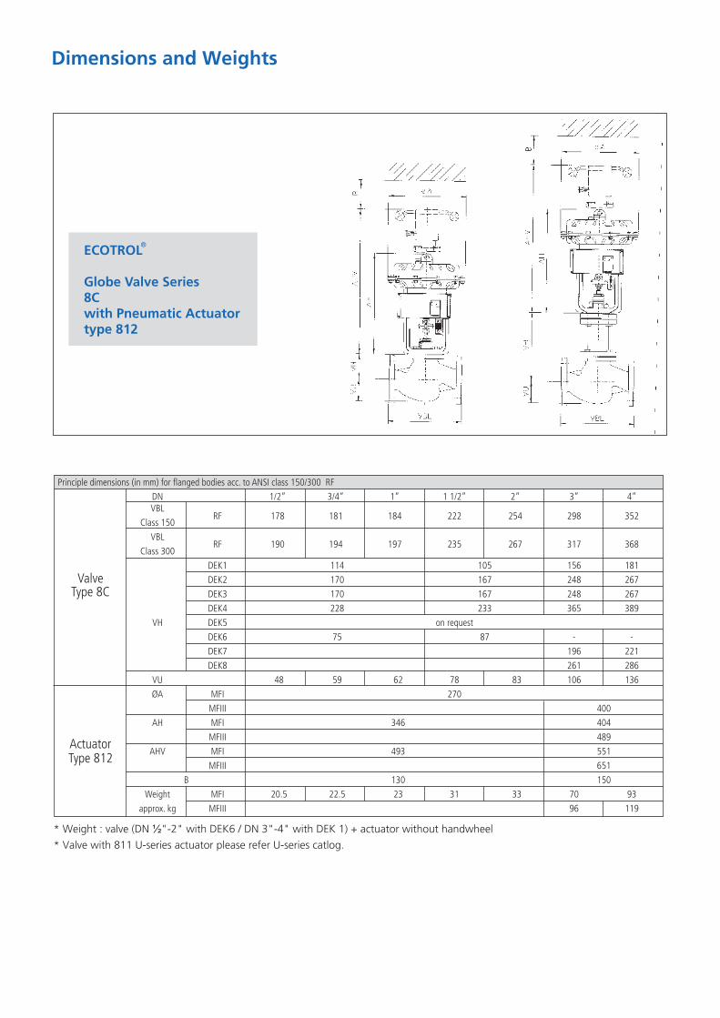
Dimensions and Weights
ECOTROL
Globe Valve Series8Cwith Pneumatic Actuatortype 812
Principle dimensions (in mm) for flanged bodies acc. to ANSI class 150/300 RFDN 1/2” 3/4” 1” 1 1/2” 2” 3” 4”VBL
RF 178 181 184 222 254 298 352Class 150VBL
RF 190 194 197 235 267 317 368Class 300
DEK1 114 105 156 181DEK2 170 167 248 267DEK3 170 167 248 267DEK4 228 233 365 389
VH DEK5 on requestDEK6 75 87 - -DEK7 196 221DEK8 261 286
VU 48 59 62 78 83 106 136ØA MFI 270
MFIII 400AH MFI 346 404
MFIII 489AHV MFI 493 551
MFIII 651B 130 150
Weight MFI 20.5 22.5 23 31 33 70 93approx. kg MFIII 96 119
* Weight : valve (DN Ω"-2" with DEK6 / DN 3"-4" with DEK 1) + actuator without handwheel* Valve with 811 U-series actuator please refer U-series catlog.
ValveType 8C
ActuatorType 812

ECOTROL
Globe Valve Series6Nwith Pneumatic ActuatorType 811/812/MA
Dimensions and Weights
Principle dimensions (in mm) for flanged bodies acc. to ANSI class 150/300 RFDN 6” 8” 10” 12” 14” 16”
VBLRF 451 543 730 (673) 850 (737) 980 (889) 1150 (1016)
Class 150VBL
RF 473 568 730 (708) 850 (775) 980 (927) 1150 (1057)Class 300
DEK1 260 292 357 394 462 518DEK2 355 407 506 543 611 667DEK3 355 407 506 543 611 667DEK4
VH DEK5DEK7 260 292 357 394 462 518DEK8 355 407 506 543 611 667
VU 3FL 189 239 305 335 395 443MFIII 400
ØA UV 530MA.60 596MFIII 625
AH UV 1006 1135MA.60 840 1010 1080
AHV MFIII 888UV 1323 1452
B 200 340Weight MFIII 190 250
approx. kg UV 225 285 355 655 745 1395MA.60 330 390 450 750 840 1490
ValveType 6N
ActuatorType 811/812/MA
on request
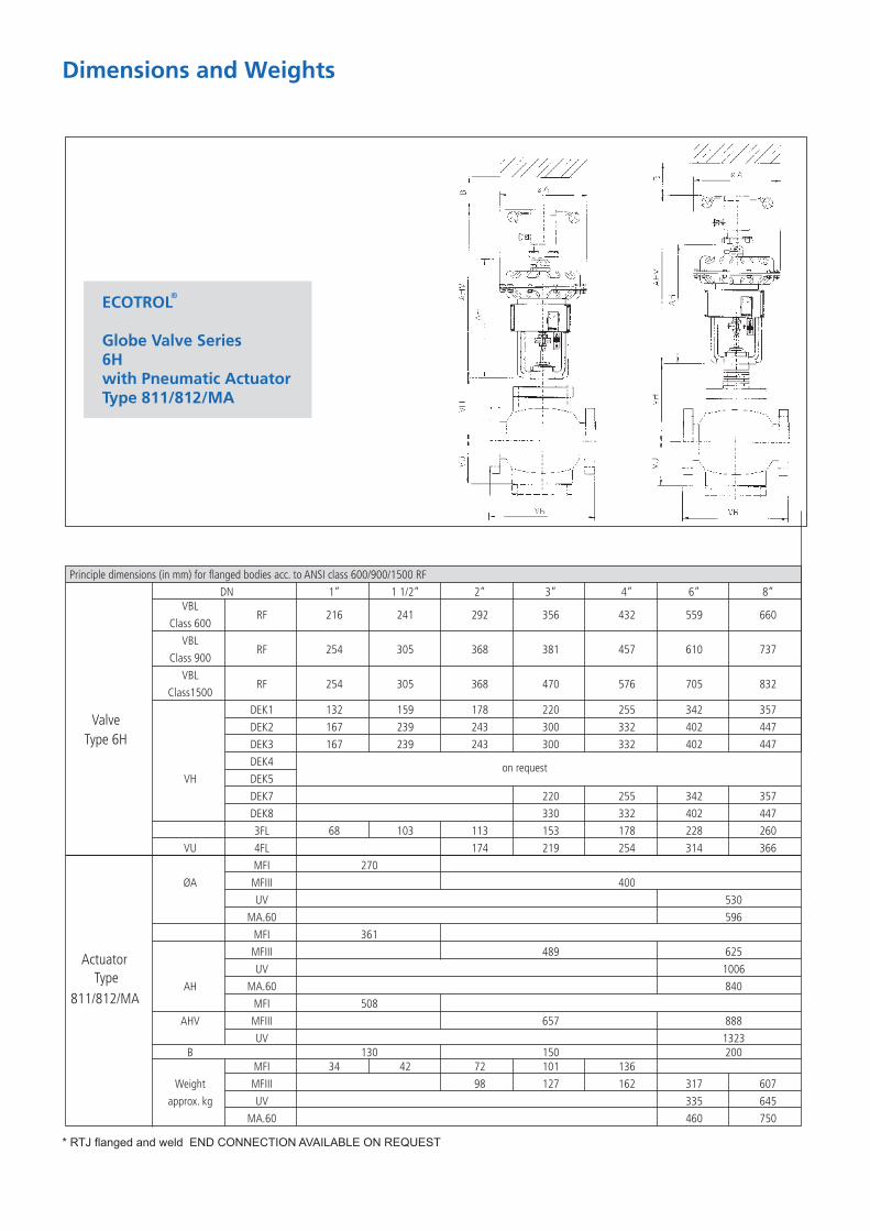
Principle dimensions (in mm) for flanged bodies acc. to ANSI class 600/900/1500 RFDN 1” 1 1/2” 2” 3” 4” 6” 8”
VBLRF 216 241 292 356 432 559 660
Class 600VBL
RF 254 305 368 381 457 610 737Class 900
VBLRF 254 305 368 470 576 705 832
Class1500DEK1 132 159 178 220 255 342 357DEK2 167 239 243 300 332 402 447DEK3 167 239 243 300 332 402 447DEK4
VH DEK5DEK7 220 255 342 357DEK8 330 332 402 4473FL 68 103 113 153 178 228 260
VU 4FL 174 219 254 314 366MFI 270
ØA MFIII 400UV 530
MA.60 596MFI 361MFIII 489 625UV 1006
AH MA.60 840MFI 508
AHV MFIII 657 888UV 1323
B 130 150 200MFI 34 42 72 101 136
Weight MFIII 98 127 162 317 607approx. kg UV 335 645
MA.60 460 750
Dimensions and Weights
ECOTROL
Globe Valve Series6Hwith Pneumatic ActuatorType 811/812/MA
ValveType 6H
ActuatorType
811/812/MA
* RTJ flanged and weld END CONNECTION AVAILABLE ON REQUEST
on request

Prefix Symbol Factor Equivalent Number-9nano n 10 one-billionth-6micro µ 10 one-millionth-3milli m 10 one-thousandth3kilo k 10 one thousandth6mega M 10 one million9giga G 10 one billion12tera T 10 one trillion
ASME B16.5 Flange dimensions for CI. 150, 300, 600, 900 and 1500 flanges (RF, RTJ)ASME B16.25 Valves - flanged and buttwelding ends
Standards
Unmachined NDT in accordance with applicable technique ASME B 16.34Material following of the order specification Finished visual testing ASME B 16.34Component hydrostatic test of all pressure containing parts ( 1, 5 x PN )ASME Valves - Seat Leakage ASME B 16.104
Testing
Useful Tables / Conversions & Applicable Standards
Size Symbol UnitLength I 1m 1000 mm 39.37 in 3.28 ft
S2 2 2Area A 1m 1550 in 10.764 ft3 3 3Volume V 1m 61020 in 35.32 ft 220 Impgal 264 US gal3 3Vol .Rate Flow Q 1m /h 16.7 I/min 0.589 ft 4.41 GMP
3Mass Flow G 1m /h x pFlow Coefficient 1 kv 1.16 cv
3 -6Density p 1 kg/m 36.1x10 0.0624 Ib/cu.ftIb/cu.in
Temperature T 0 K -273°C -273 x 9/5 + 32F0 x 9/5 + 32F
Mass m 1 kg 2.204 Ib 35.273 ozForce F 1 N 0.102 kp 0.225 Ibf
5 2Pressure p 10 Pa 1 Bar 14.5 Ib/inPower P 1 kw 860 kcal/h 1.34 hp
2 4Viscosity h 1 Pa x s 1 Ns/m 1 x 10 Stoke
Unit Unit Unit Unit

Std. Kv Values
Size LiftPercentage
16 3 0.06 0.06
16 4 0.1 0.1
16 4 0.16 0.16
16 5 0.25 0.25
16 5 0.4 0.4
16 5 0.63 0.63
16 8 1 1
16 10 1.6 1.6
16 12 2.5 2.5
16 15 4 4
1”, 1Ω” 16 20 6.3 6.3
1", 1Ω",2" 16 25 10 10
16 30 16 16
16 36 25 25
2" 16 46 40 40
3" 30 46 40 40
30 50 63 63
30 80 100 100
4" 30 100 160 160
Seat Dia(mm) Kv-Linear Kv-Equal
Ω”,1”
1Ω”, 2"
3”, 4"
Notes:1. for 3” Pr. Bal. select Seat Dia 80 mm only2. for 4” Pr. Bal. select Seat Dia 100 mm only3. Customised Kv values are available as per requirement in perforated trims
8CX-P1 Metal Seated/Soft Seated Valve
Size Lift Seat Dia(mm) Kv-Linear Kv-Equal Percentage
60 90 150 150
6", 8" 60 113 260 260
60 143 380 380
8" 60 172 650 650
10" 100 143 380 380
100 172 650 65010",12",14"
100 220 900 900
12",14" 100 282 1300 1300
14" 100 313 1800 1800
120 282 1300 1300
16" 120 313 1800 1800
120 400 2500 2500
Notes:1. for 6" Pr. Bal. select Seat Dia 143 mm Only2. for 8" Pr. Bal. select Seat Dia 172 mm Only3. for 10" Pr. Bal. select Seat Dia 220 mm Only4. for 12" Pr. Bal. select Seat Dia 282 mm Only5. for 14" Pr. Bal. select Seat Dia 313 mm Only6. for 16" Pr. Bal. select Seat Dia 400 mm Only7. Customised Kv values are available as per requirement in perforated trims
6NX-P1 Metal Seated/Soft Seated Valve
Size Lift Seat Dia(mm) Kv-Linear Kv-Equal Percentage
20 3 0.06 0.06
20 3 0.1 0.1
20 3 0.16 0.16
20 4 0.25 0.25
20 5 0.4 0.4
20 6 0.63 0.63
20 7 1 1
20 9 1.6 1.6
20 11 2.5 2.5
20 16 4 4
1" 20 19 7 7
1", 1Ω" 20 24 11 11
20 32 18 18
20 37 26 26
2" 30 32 18 18
2" 30 37 26 26
2",3" 30 48 43 43
30 62 68 68
30 73 100 100
4" 30 90 150 150
6" 60 90 150 150
60 113 260 260
60 143 380 380
8" 60 172 650 650
100 143 380 380
10" 100 172 650 650
100 220 900 900
Notes:1. for 3” Pr. Bal. select Seat Dia 73 mm only2. for 4” Pr. Bal. select Seat Dia 90 mm only3. for 6” Pr. Bal. select Seat Dia 143 mm only4. for 8” Pr. Bal. select Seat Dia 172 mm only5. for 10” Pr. Bal. select Seat Dia 220 mm only6. Customised Kv values are available as per requirement in perforated trims
6HX-P1 Metal Seated/Soft Seated Valve
6",8"
3",4"
1Ω"
Ω",1"

Notes

Notes

Section View of Valve with Smart Positioner(Tubeless Mounting)
Valve with E/P Positioner(with External Tubing)
Valve with U-Series Actuator and ROBOTER-902
Valve with sandwich Bonnet with Hand wheel
Valve with Std. Bonnet with Hand wheel.

www.forbesmarshall.com
Forbes Marshall Arca Pvt. Ltd.A-34/35, MIDC, Industrial Estate, ‘H’ Block, Pimpri, Pune - 411 018. India.Tel.: 91(0)20 - 27442020Fax: 91(0)20 - 27442040 E-mail: [email protected]
Domestic:Ahmedabad, Alibag, Bangalore, Bhopal / Indore, Chandigarh, Chennai, Coimbatore, Delhi, Hyderabad, Jamshedpur, Kolkata, Mumbai, Nagpur, Navi Mumbai, Surat, Trichy, Vadodara, VisakhapatanamInternational Operations: [email protected], Canada, Egypt, Indonesia, Iran, Kenya, Malaysia, Nepal, Sri Lanka, Thailand, U.A.E. (Instrumentation) (Boilers & Boiler Accessories)USA,
DOC#
CIG
/090
9/28
/V1.
R0