Embed Size (px)
Citation preview

MID:COM E:Count
E:Count MCR-05 and E:Count LT MCR-09
User’s Guide
Reference for Operating the
MID:COM E:Count MCR-XX Electronic Registers
Midwest Computer Register, Corp.
1605 170th Street
Hampton, IA 50441
Telephone: 641-456-4848
Fax: 641-456-4600
E-Mail: [email protected]
Web: www.MidComCorp.com
MID:COM THE ONE THAT WORKS!

2/95
TABLE OF CONTENTS
TABLE OF CONTENTS ............................................ 2
TABLE OF FIGURES ............................................. 6
Section 1 - TECHNICAL SPECIFICATIONS ......................... 9
Electrical Requirements .................................... 9
Operating Environment ...................................... 9
Enclosure .................................................. 9
Environmental Testing ...................................... 9
Interconnect ............................................... 9
Metrological Sealing ....................................... 9
Mounting ................................................... 9
Inputs/Outputs ............................................ 10
Pulse Input ............................................ 10
Pulse Output ........................................... 10
Powered Control Outputs ................................ 10
Analog Input ........................................... 10
Communications ......................................... 10
Calibration ............................................... 10
Registration Capacity (Units) ............................. 10
Section 2 - LAYOUT .......................................... 11
Special Note on Keyboard Entry ............................ 12
Section 3 - WIRING AND INSTALLATION ......................... 13
E:Count Serial Cable Connections .......................... 17
Spike Suppressor Installation ............................. 20
Reel Motor Solenoid Spike Suppressor Installation ......... 20
SV104 Valve Wiring Instructions ........................... 23
SV104 Valve Operation ..................................... 23
SV101 Solenoid Security/Preset Valve ...................... 25
Security Valve Installation ............................... 27
Security Valve Port Designations .......................... 27
Security Valve Operation .................................. 27
LC & TCS METERS - METER RATIOS AND 1:1 PACKING GLANDS ..... 28
LC & TCS METERS - METER RATIOS AND 2:1 PACKING GLANDS ..... 29
E:Count Register Back Panel Cable Connections ............. 30
E:Count ‘Computer’ Wiring Harness Connection .............. 31
Section 4 – FIRMWARE VERSIONS AND COMMAND REFERENCE ......... 32
Firmware Versions ......................................... 32
Section 5 - OPERATION ....................................... 35
E:Count Overview and Theory of Operation .................. 35
Meter Calibration and Temperature Compensation........... 35
Meter Calibration (Un-compensated)....................... 35
Temperature Compensation................................. 36
Product Codes............................................ 38
Electronic Air Sensor.................................... 39
Flow Rate................................................ 40
Mass or Volume........................................... 40

3/95
Compensation Table Reference............................. 40
Power Latching ............................................ 41
Power Failure ............................................. 41
Power Failure During a Host Mode Delivery................ 42
See the E:Count Host Interface Guide for more information. 42
Display Microprocessor - Errors and Detection ............. 43
HostFix ................................................... 44
Section 6 – REQUIRED E:COUNT CONFIGURATION SETTINGS ......... 45
Section 7 - MODES ........................................... 46
Delivery Mode ............................................. 46
Hose Packing............................................. 48
Broken Valve Detection................................... 48
Preset Operation......................................... 49
No Preset Entered Before the Delivery.................... 50
Preset on Dollars........................................ 50
Batch Mode Preset (E179 Rev3 and earlier)................ 50
Multiple Presets in a Single Delivery.................... 51
Editing Product Price During (or After) Delivery......... 52
Multiple Product Price Adjustment........................ 52
Delivery Menu ............................................. 53
Delivery Menu Categories................................. 54
HOSEPK – Open Valve to Pack the Hose ................... 54
PRCODE – Product Code .................................. 54
QOB – Quantity on Board ............................. 54
MONEY – Currency Mode ................................. 54
TIMOVR – No Flow Timer Override ........................ 55
SHIFT – Shift Report .................................. 55
DRIVER – Driver Code ................................... 55
TOTAL – Totalizer ..................................... 55
DISVOL – Volumes ....................................... 56
TEMP F – Current Product Temperature in Degrees F ...... 56
TEMP C – Current Product Temperature in Degrees C ...... 56
CALTKT – Calibration Report ............................ 56
SETUP – Enter Setup Mode .............................. 56
EXIT – Exit Delivery Menu ............................ 56
Currency Mode ............................................. 57
Currency Mode Categories................................. 58
PRICE – Set the Price for the Current Product ......... 58
TAX 1 – Set Tax 1 Rate ................................ 58
TXTYP1 – Set Tax 1 Type ................................ 58
TAX 2 – Set Tax 2 Rate ................................ 58
TXTYP2 – Set Tax 2 Type ................................ 59
TAXSUB – Setup Subtotal Tax ............................ 59
DISCNT – Set the Discount Rate ......................... 59
DSCTYP – Set the Discount Type ......................... 59
DSCDAY – Set the Discount Days ......................... 60
PRCADJ – Adjust the price for all valid products ....... 60
4/95
EXIT – Exit Money Mode ............................... 60
Setup Mode ................................................ 61
Setup Categories......................................... 62
NEWCOD – Set Security Code ............................. 62
STAGE1 – Stage 1 (Fast Flow) Shutoff Volume ............ 62
STAGE2 – Stage 2 (Slow Flow) Dwell Volume .............. 62
TIME – System Time ................................... 62
DATE – System Date ................................... 62
SALE – Next Sequential Sale Number ................... 63
TRUCK – Truck Number .................................. 63
CURNCY – Currency Setting .............................. 63
PS RQD – Preset Required ............................... 63
PRINTR – Printer Setup ................................. 63
COPIES – Thermal Printer Ticket Copies ................. 64
HOSEPK – Hose Packing Setting .......................... 64
SS RST – Enable or Disable START/STOP Reset ............ 64
6501PF – 6501 Print Format ............................. 65
HOSTFX – Require Prefix Character for Host Commands .... 65
KEYSON – Print + Preset Key Setting ................... 66
EXIT – Exit Setup Mode ............................... 66
Calibration Mode .......................................... 68
Auto-Calibration......................................... 69
Calibration Menu Categories.............................. 71
PRCODE – Product Code .................................. 71
DISVOL – Volumes ....................................... 71
ATOCAL – Enter Prover Volume for Auto-Calibration ...... 71
CALFAC – Calibration Factor ............................ 71
TEMP F – Temperature in Degrees Fahrenheit ............. 72
TEMP C – Temperature in Degrees Celsius ................ 72
TABLE – Table Value at Current Temperature ............ 72
PLSREV – Pulses per Revolution in L415/E180+ and EM13+ 72
CHANNL – Dual or Single Channel Encoder Input in
L415/E180+ ............................................. 72
FLODIR – Product Flow Direction through the Meter/Encoder
....................................................... 72
MRATIO – Meter Ratio ................................... 73
CMPTBL – Temperature Compensation Table Value .......... 74
SERIAL – E:Count Serial Number ......................... 74
TIMER – Timer Setup ................................... 74
REGNUM – Set the Active Register Number to Configure ... 75
U TYPE – Select Unit Type .............................. 75
UNITS – Select Units .................................. 75
PGROSS – Print the Gross Volume on Delivery Tickets .... 75
DECMAL – Use Tenths of Units or Whole Units ............ 76
AIRSEN – Optical Air Sensor ............................ 76
PROBE – Type of Temperature Probe Installed ........... 77
BRKVLV – Enable or Disable the Broken Valve setting. ... 77

5/95
DEMO – Enable or Disable the Demo Mode setting. ...... 77
EXIT – Exit Calibration Menu ......................... 77
Program Mode .............................................. 79
Power-Up .................................................. 80
Section 7 – SAMPLE TICKETS .................................. 81
Section 8 – APPENDICES ...................................... 84
Appendix A – E:Count MCR-05 to 8000 Interface ............. 84
Theory of Operation .................................... 84
Return on Investment ................................... 84
Valve Options .......................................... 84
Mounting ............................................... 87
Wiring ................................................. 87
Terminal Blocks ........................................ 87
Field Wiring Connector Designations .................... 88
INDEX ....................................................... 89
VERSION HISTORY ............................................. 93

6/95
TABLE OF FIGURES
Figure 1. MCR-05 Layout Figure 2. MCR-09 LT Layout ........ 11
Figure 3. E:Count MCR-05 Wiring Diagram...................... 13
Figure 4. E:Count LT MCR-09 Wiring Diagram................... 14
Figure 5. E:Count Power Cable Connections.................... 15
Figure 6. E:Count Power Cable Connector...................... 16
Figure 7. E:Count Optical Sensor Harness Connection.......... 19
Figure 8. Ferrite Cylinder Clamp Installation................ 21
Figure 9. Solenoid Spike Suppressor Wiring Diagram........... 22
Figure 10. SV104 2 Stage Solenoid Valve...................... 24
Figure 11. SV101 Security Valve Installation................. 24
Figure 12. LC & TCS Meter 1:1 Packing Gland Installation..... 28
Figure 13. 1:1 Packing Gland Meter Ratios.................... 28
Figure 14. LC & TCS Meter 2:1 Packing Gland Installation..... 29
Figure 15. 2:1 Packing Gland Meter Ratios.................... 29
Figure 16. E:Count Register Cable Connections................ 30
Figure 17. E:Count Computer Wiring Harness Connection........ 31
Figure 18. E:Count Quick Command Reference E179.............. 33
Figure 19. E:Count Quick Command Reference E180.............. 34
Figure 20. E:Count Delivery Process.......................... 46
Figure 21. E:Count MRATIO Values............................. 73
Figure 22. E:Count Compensation Table Numbers................ 74
Figure 23. E:Count Temperature Probes and Serial Numbers..... 78
Figure 24. E:Count Temperature Probes........................ 78
Figure 25. E:Count Program Mode.............................. 79
Figure 26. E:Count Delivery Tickets.......................... 81
Figure 27. Thermal Printer Ticket with Logos................. 81
Figure 28. E:Count Calibration and Shift Tickets............. 83

7/95
Trademarks
MID:COM E:Count and their integrated software and hardware
components are trademarks of Midwest Computer Register Corp.
(MID:COM). Microsoft, MS, and MS-DOS are registered trademarks,
Windows is a trademark of Microsoft Corporation. Other brand
and product names mentioned in this publication are trademarks
or registered trademarks of their respective holders.
Copyright Notice
ECount Users Guide E180E0 v1.00.docx
© 2006-2008 Midwest Computer Register, Corp. All rights
reserved. Neither this publication nor any part of this
publication may be copied, photocopied, reproduced, translated,
or reduced to any electronic medium or machine readable form
without the prior written permission of:
Midwest Computer Register, Corp.
1605 170th St.
PO Box 376
Hampton, Iowa 50441, USA
641-456-4848
www.midcomcorp.com
Disclaimer
Midwest Computer Register, Corp. provides this document and the
software "as is" without any warranty of any kind, either
expressed or implied; including but not limited to, the implied
warranties of merchantability or fitness for a particular
purpose.
Midwest Computer Register, Corp. reserves the right to make
improvements and modifications to this document, and the
products described in this document, at any time and without
notice.
Midwest Computer Register, Corp. shall not be liable for any
errors contained herein or for incidental and consequential
damages in connection with the furnishings, performance, or use
of this material.

8/95
Contact Information
You have several ways to interact with Midwest Computer
Register, Corp. and its staff. If you have a suggestion you can
email, write, or call us.
Sales: [email protected]
Support: http://www.midcomcorp.com/Contact.html
Postal Address
MID:COM
1605 170th St
PO Box 376
Hampton, Iowa 50441
Phone Numbers
Phone: 641-456-5205
Fax: 641-456-4600

9/95
Section 1 - TECHNICAL SPECIFICATIONS
Electrical Requirements
Operating Voltage: 10-30 VDC unregulated
Operating Current: Standby 275 mA
Up to 3 solenoids activated: 1 A additional each
Operating Environment
Outdoors exposed to elements
Temperature Range: -40ºC to +60ºC (-40ºF to 140ºF)
Humidity: 100% Condensing
Enclosure
Aluminum permanent mold casting with epoxy powder coat
Rating: IP-66 and NEMA-4
Silicone gasket for keyboard and cover seals
Calibration and Program Screws seal with BUNA ‘O’ Ring
Environmental Testing
Temperature Range: -40ºC to +60ºC (-40ºF to 140ºF)
Vibration: 3 Gs, 30 Hz, 2 axes, 72 hours
Shock: 4 foot drop to concrete, 3 axes, 5 times each
Interconnect
Up to 5 multi-pin circular plastic connectors
Sealed to IP-66 standards
Compensator Probe uses a 1/4” NPT compression fitting with
thread sealant
[MCR-09 LT: ½” NPT Conduit Hub – Internal Terminal Blocks]
Metrological Sealing
Drilled head screws for:
Calibration Switch
Program Switch [MCR-09 LT: Program Switch Not Available]
Enclosure Cover
All Mounting Accessories
Mounting
Industry standard ‘Veeder-Root’ bolt circle with 1/4-20 threads
[MCR-09 LT: MID:COM Standard Bolt Circle - 1/4-20 threads]
Adapters available to mount all currently available meters

10/95
Inputs/Outputs
Pulse Input
Internal: 100 pulse-per-revolution (ppr) dual channel
quadrature encoder for rotational input from positive
displacement meters
External: Single or dual channel input from meters with
electrical output, 3 to 30 V signal
Pulse Output
Calibrated pulse output for remote counting or monitoring
devices.
Raw encoder pulse output for connection to small volume
piston provers. [MCR-09 LT: Raw Encoder Pulse Output Not
Available]
Powered Control Outputs
Three (3) High-side 12 V drivers for use with solenoid valves
and other ancillary devices.
[MCR-09 LT: One (1) High-side 12 V driver]
Analog Input
One (1) 4 to 20 mA current loop for applications including
tank gauging. [MCR-09 LT: Analog Input Not Available]
Communications
Four (4) RS-232 compliant serial ports for use with printers,
external computing devices, etc.
[MCR-09 LT: Two (2) RS-232 compliant serial ports]
Calibration
Prescale Factor (MRATIO) Range: 1 to 99
Calibration Factor Range: 0.0001 to 1.9999
Compensation Accuracy: Four (4) decimal places from lookup
table
Registration Capacity (Units)
Delivery: -99999.9
Totalizer: 9999999.9

11/95
Section 2 - LAYOUT
Figure 1. MCR-05 Layout Figure 2. MCR-09 LT Layout
GALLONSLITRES ‘GALLONS’ or ‘LITRES’ indicates the
current Volume Mode (US or Metric).
VOLUME CORRECTED TO 60F15C Displayed whenever the Temperature
Compensation is active. ‘60F’ in
Gallons Mode, 15C’ in Liters mode.
DELIVER Indicates Delivery Mode is active
and will display until the Fuel
Delivery Ticket prints.
PRESET Indicates the Preset Volume is
being changed. [MCR-09 LT: Preset
is Optional – the <TOTAL> key may
be used to display the Totalizer]
PRODUCT Indicates the Product Code is being
changed.
SETUP Displayed in the Delivery Menu and
the Calibration Menu.
CALIBRATE Indicates the Calibration Screw has
been backed out - will display
until the Calibration Screw is
tightened.

12/95
Special Note on Keyboard Entry
The E:Count uses special technique called PRESS & HOLD for
keyboard entry. This technique eases keyboard operation,
especially when wearing gloves, in the absence of any audible
or tactile feedback. Simply press a button and wait for the
desired action.
Examples:
• For menus press & hold the mode key until the selection
appears.
o PRESS & HOLD <START/STOP> to enter that selection.
o PRESS & HOLD <START/STOP> to exit the selection.
• To enter number PRESS & HOLD the <RIGHT> or <LEFT> arrow
keys to select the digit to be changed. To change the
number PRESS & HOLD the <UP> or <DOWN> arrow.
• To start a delivery PRESS & HOLD <START/STOP>.
• To enter a preset PRESS & HOLD <PRESET>.
Pressing and releasing a button may give results but it is
only coincidental that the button was held long enough.

13/95
Section 3 - WIRING AND INSTALLATION
Figure 3. E:Count MCR-05 Wiring Diagram

14/95
Figure 4. E:Count LT MCR-09 Wiring Diagram
[MCR-09 LT: The Power Control Module is not used by the E:Count
LT MCR-09.]
Valve
E:Count LT Register Head
Rear View
12 Volt Supply
½” Conduit & NB
15/95
E:Count Power Cable Connections
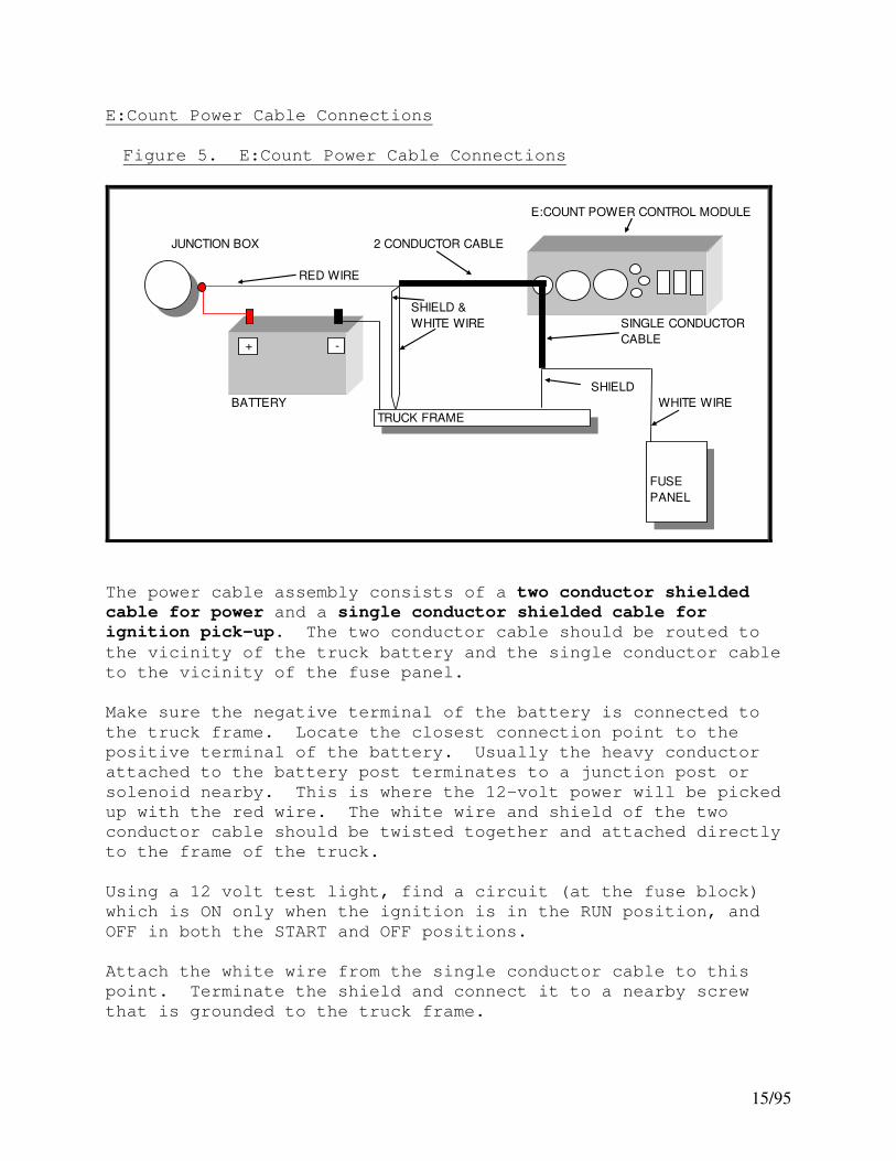
Figure 5. E:Count Power Cable Connections
E:COUNT POWER CONTROL MODULE
JUNCTION BOX 2 CONDUCTOR CABLE
RED WIRE
SHIELD &
WHITE WIRE SINGLE CONDUCTOR
CABLE
SHIELD
BATTERY WHITE WIRE
+ -
TRUCK FRAME
FUSE
PANEL
The power cable assembly consists of a two conductor shielded
cable for power and a single conductor shielded cable for
ignition pick-up. The two conductor cable should be routed to
the vicinity of the truck battery and the single conductor cable
to the vicinity of the fuse panel.
Make sure the negative terminal of the battery is connected to
the truck frame. Locate the closest connection point to the
positive terminal of the battery. Usually the heavy conductor
attached to the battery post terminates to a junction post or
solenoid nearby. This is where the 12-volt power will be picked
up with the red wire. The white wire and shield of the two
conductor cable should be twisted together and attached directly
to the frame of the truck.
Using a 12 volt test light, find a circuit (at the fuse block)
which is ON only when the ignition is in the RUN position, and
OFF in both the START and OFF positions.
Attach the white wire from the single conductor cable to this
point. Terminate the shield and connect it to a nearby screw
that is grounded to the truck frame.
16/95
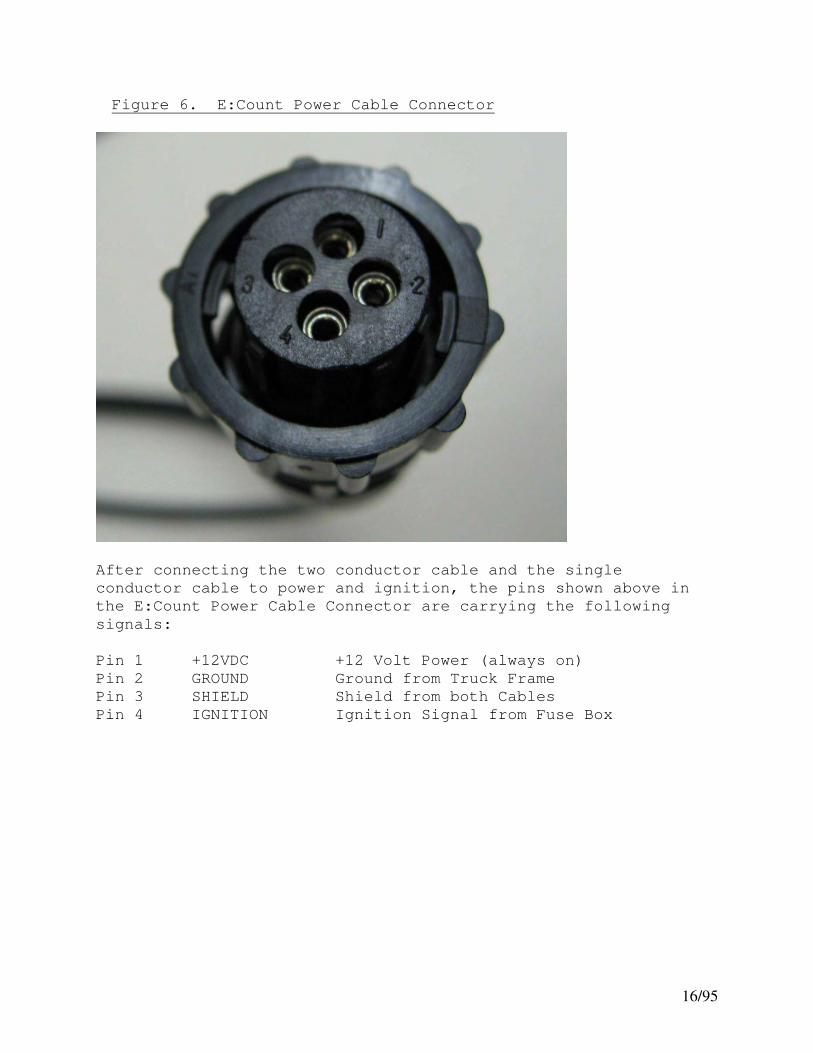
Figure 6. E:Count Power Cable Connector
After connecting the two conductor cable and the single
conductor cable to power and ignition, the pins shown above in
the E:Count Power Cable Connector are carrying the following
signals:
Pin 1 +12VDC +12 Volt Power (always on)
Pin 2 GROUND Ground from Truck Frame
Pin 3 SHIELD Shield from both Cables
Pin 4 IGNITION Ignition Signal from Fuse Box

17/95
E:Count Serial Cable Connections
Device Port Cable Part#
Handheld/Laptop Serial Port (DTE) PCM-Serial1 (DCE) Straight 9F/9M 114-0100
Handheld/Laptop Serial Port (DTE) PCM-Printer (DCE) Straight 9F/9F 114-0271
ComLink (DCE) PCM-Serial2-AUX (DTE) Straight 9F/9M 114-0100
GPS (DCE) PCM-Serial2-AUX (DTE) Custom *
Blaster (Cognitive) (DTE) PCM-Printer (DCE) Custom Straight 3-Wire 9F/9M 702-0091 ++
Blaster (Cognitive) (DTE) 8000-Printer (DTE) Custom NULL 3-Wire 9F/9M 702-0089 +
BlueSnap BlueTooth Adapter (DCE) PCM-Printer (DCE) NULL 9F/9M 114-0273
Citizen CT-S310 (DTE) PCM-Printer (DCE) Straight 9F/25M 114-0089
Citizen CT-S4000 (DTE) PCM-Printer (DCE) Straight 9F/25M 114-0089
Citizen CT-S601 (DTE) PCM-Printer (DCE) Straight 9F/25M 114-0089
Midcom/Citizen CT-S651 (DTE) PCM-Printer (DCE) Straight 9F/25M 114-0089
Datamax M4te Printer (DCE) PCM-Printer (DCE) NULL 9F/9M 114-0273 ****
Epson TM-220 (DTE) PCM-Printer (DCE) Straight 9F/25M 114-0089 **
Epson TM-295 (DTE) PCM-Printer (DCE) Straight 9F/25M 114-0089
Epson TM-88 (DTE) PCM-Printer (DCE) Straight 9F/25M 114-0089
Fujitsu FP-460 (DTE) PCM-Printer (DCE) Straight 9F/25M 114-0089
MID:COM Impact Printer (DCE) PCM-Printer (DCE) NULL 9F/9M 114-0273
Midcom/Axiom/Telesto Thermal Printer (DTE) PCM-Printer (DCE) Straight 9F/9F 114-0271
Printek RT43 (BlueTooth) None, Uses BlueTooth --- ---
Printek RT43 (Serial) PCM-Printer (DCE) NULL 9F/9M 114-0273 ****
Zebra RW420 (DCE) PCM-Printer (DCE) Custom 702-0116 ***
* Cable depends on GPS Reciever, contact Midcom.
** TM-220 must be in XON/XOFF, set DIP1 SW3 to ON.
*** Zebra RW-420 requires DSR high to be awake, Pin4 on DE9 is DTR --> DSR on Pin7 of 10 pin connector.
**** Requires Datamax Cable: DB9-FRTANGRJ127NONCOIL + M/F Null Modem Adapter
+ Blaster puts +5 VDC on Pin9, use Midcom cable with 8000 to isolate Pin9 or printer may be destroyed.
++ E:Count PCM uses only 3-Wire Comms so Pin9 is already isolated, but custom 3-wire cable recommended.
+++ Requires Printek Cable: Part # 91849 "RT43 RS232 Cable" + M/F Null Modem Adapter
Wired Cable - Printer to PCM Part # Opposite Gender for Wireless Part #
Custom Straight 3-Wire 9F/9M 702-0091 Custom Straight 3-Wire 9M/9M 114-0384
Custom NULL 3-Wire 9F/9M 702-0089 Custom NULL 3-Wire 9M/9M 114-0385
NULL 9F/9M 114-0273 NULL 9M/9M 114-0386
Straight 9F/25M 114-0089 Straight 9M/25M 114-0387
Straight 9F/9F 114-0271 Straight 9M/9F 114-0100

18/95
PRINTER NOTES:
To connect a Printer to the E:Count PCM via Digi RF Radios:
1. Connect the RF Radio to the PCM-Printer port via a NULL 9F/(M
cable (Part # 114-0273).
2. Connect the RF Radio to the Printer using the opposite gender
of the appropriate cable for that printer.
Refer to the full Midcom ECount Printer Notes document available
on the Midcom website for all makes and models of printers
supported by the ECount MCR-05 and the ECount LT MCR-09.
The E:Count PCM-PRINTER port is DCE, but the MID:COM 8000
Printer Port (the outside serial port on the 8000 computer when
facing the back) is DTE – this means that different cables will
be required to connect the 8000 computer to an external printer.
Contact MID:COM for more information.
The 8000-Cognitive Blaster cable is NULL 9F/9M, the E:Count-
Cognitive cable is STRAIGHT 9F/9M. The correct cable must be
used for the application, however a null modem adapter with the
8000 cable we manufacture may safely be used with the E:Count
(since the danger is the cable used with the 8000). The
Cognitive printer puts out 5v on pin 9, and the 8000 puts out 12
V on pin 9. If a cable is used with the Cognitive printer and
the 8000 that does *not* isolate pin 9 the printer internal
power supply will be destroyed, therefore our 8000-Cognitive
cable is 9M9F Null and only connects pins 2, 3, and 5. MID:COM
Part Number 702-0089 is recommended with an 8000.
The E:Count-Cognitive Blaster cable is 9M9F straight-through,
since the PCM only has pins 2,3,5 connected to the printer any
9M9F straight-through cable may safely be used as the power is
output from the printer on pin 9 and is not connected in the
PCM. MID:COM Part Number 114-0100 or 702-0091 (which connects
only pins 2,3,5) are the recommended cables when used with the
E:Count PCM.

19/95
Optical Sensor
Figure 7. E:Count Optical Sensor Harness Connection
The Optical Sensor connector for FUEL OIL (Part # 702-0083) has
two cables:
VALVE – 1 black wire, 1 white wire
SENSOR – 1 black wire, 1 red wire, 1 clear wire
The Optical Sensor connector for PROPANE (Part # ) has
one cable:
SENSOR – 1 black wire, 1 red wire, 1 clear wire
Optical Sensor Harness
Labeled “MP”

20/95
Spike Suppressor Installation
All MID:COM systems are shipped complete with one spike
suppressor per register head, these are included in the
installation kit. The spike suppressor must be installed across
each hose reel solenoid – refer to the Solenoid Spike Suppressor
Wiring Diagram (refer to the Table of Figures for a page
number). It also may be necessary to install more than the one
on the hose reel solenoid or other spike producing components of
the truck electrical or pumping system. If so, contact the
factory to order additional spike suppressors.
Reel Motor Solenoid Spike Suppressor Installation
The spike suppressor is a heavy-duty diode used to kill the
high-voltage inductive kickback that occurs when the reel motor
switch is released and the solenoid contactor opens. The spikes
that are produced can cause electrical noise interference with
any type of electronic equipment.
Most solenoids are equipped with a single screw stud that is
connected to one side of the coil, with the other side of the
coil either grounded or connected to 12-volts. Before
installing the suppressor, it’s important to determine which
configuration you have. A 12-volt test light works well for
this.
Connect the light between the switch stud and ground. If the
light does not glow at all, press the reel switch and it should
light. This is a grounded coil configuration. Connect the red
lead of the suppressor to the stud, and the black lead to
ground.
If the light glows even dimly, press the reel switch and it
should go out altogether. This is a hot coil configuration.
Connect the black lead to the stud and the red lead to 12-volts
(the hot side of solenoid).
If the solenoid has two studs, and both have a wire going to
them, check both as described above and connect the suppressor
to whichever stud reacts like the grounded coil configuration.

21/95
Figure 8. Ferrite Cylinder Clamp Installation

22/95
Figure 9. Solenoid Spike Suppressor Wiring Diagram
23/95
SV104 Valve Wiring Instructions
3 Conductor Valve Cable Connections:
Red = Connect to Both 1st and 2nd Stage
Black = 1st Stage Shut Down
White = 2nd Stage Shut Down
The voltage present on an individual wire is dependent on the
device connected to the valve:
E:Count Register 8000 Computer or SLS
---------------- --------------------
Red Wire Constant Ground Constant +12 VDC
Black Wire Switched +12 VDC Switched Solenoid Ground
White Wire Switched +12 VDC Switched Solenoid Ground
Valve Connections: Red to one wire from each solenoid.
1st Stage Shut Down (Black) to solenoid
Identified on tag as #EF8016G1
2nd Stage Shut Down (White) to solenoid
Identified on tag as #EFHT8003G1
SV104 Valve Operation
Once solenoids are energized product can begin to flow. Upon
reaching 1st Stage Shut Down the large valve will slowly shut
down while pressure is equalized. This is a spring assisted
closure. This then creates a slow flow of approximately 10 GPM.
Once preset or 2nd Stage Shut Down is reached the valve will
completely close.
NOTE: If Solenoids have a third wire that is green with yellow
stripe, it can be cut off as it is not used.
NOTE: DO NOT USE DIODES WHEN HOOKING VALVES UP TO AN E:COUNT
REGISTER.

24/95
Figure 10. SV104 2 Stage Solenoid Valve
Figure 11. SV101 Security Valve Installation

25/95
SV101 Solenoid Security/Preset Valve
For E:Count
PART NUMBER DESCRIPTION
Valve:
706-0045 Security/Preset valve for use with the E:Count
system, equipped with a short cable and 4
position circular plastic connector.
Wiring:
706-0045 Route the valve cable from the valve to the back
of the E:Count register and connect with mating
receptacle.

26/95
PART NUMBER DESCRIPTION
Plumbing:
MID:COM has supplied valves manufactured by two different
companies: Asco and Parker-Skinner. Although they are
functionally the same, they are constructed differently and
their ports are numbered differently.
Valves No Longer Available:
ASCO P/N 832058 Green solenoid housing with three
ports on main valve body. 1
Parker-Skinner P/N X54LB2XXX Gold solenoid housing with two
ports on main valve body, and one
port out the solenoid cover. 1
Parker-Skinner P/N 714X50202A Blue solenoid housing with three
ports on the main valve body. 1 2
Parker-Skinner P/N 7133TVN Black solenoid housing with three
ports on main valve body. 1 2
Parker-Skinner P/N 71335SN Black solenoid housing with two
ports on the main valve body, and
one out the solenoid top. 1 2
Current Production Valve:
Parker-Skinner P/N 7139 Black solenoid housing with two
ports on the main valve body, and
one out the solenoid top. 2
Notes:
1. This valve is no longer available. 2. A Repair Kit is available for this valve.

27/95
Security Valve Installation
1. Make sure the meter is blown down and safe to break pipe connections.
2. Remove the vapor line going to the differential valve. 3. Referring to the port designations below, connect the
“common” port to the differential valve with a pipe nipple.
NOTE: Fittings and hoses are user supplied.
4. Connect the vapor line to the “vapor” port. 5. Connect the “pressure” port to any source of liquid
pressure upstream of the differential valve.
Security Valve Port Designations
SKINNER #X54LB PORT 1 VAPOR Vapor Line
PORT 2 COMMON Differential Valve
PORT 3 PRESSURE Source of Pressure
SKINNER #714X & 7133 PORT 1 VAPOR Vapor Line
PORT 2 COMMON Differential Valve
PORT 3 PRESSURE Source of Pressure
ASCO #832058 PORT 1 COMMON Differential Valve
PORT 2 VAPOR Vapor Line
PORT 3 PRESSURE Source of Pressure
Security Valve Operation
When the valve is de-energized, liquid pressure is ported to the
differential valve holding it closed. When the valve is
energized, the liquid is bled back through the vapor line and
the pressure port is cut off. The meter and differential valve
then operate as if the valve was not in the system.
28/95
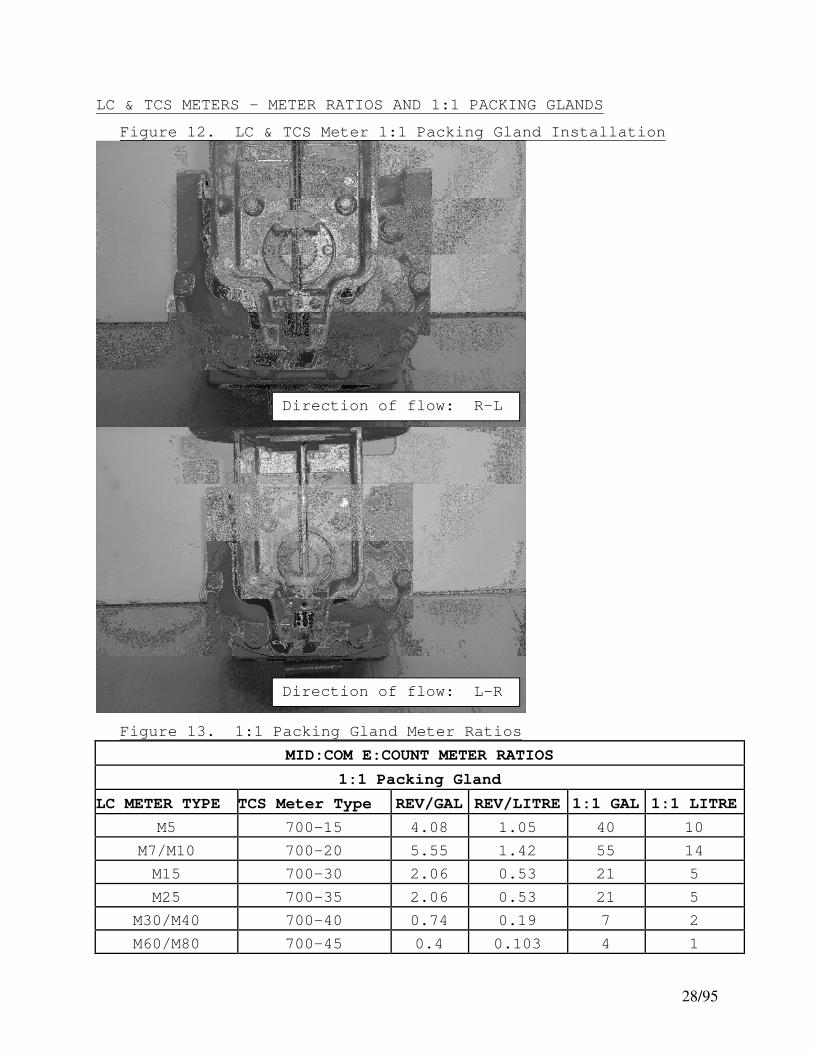
LC & TCS METERS - METER RATIOS AND 1:1 PACKING GLANDS
Figure 12. LC & TCS Meter 1:1 Packing Gland Installation
Figure 13. 1:1 Packing Gland Meter Ratios
MID:COM E:COUNT METER RATIOS
1:1 Packing Gland
LC METER TYPE TCS Meter Type REV/GAL REV/LITRE 1:1 GAL 1:1 LITRE
M5 700-15 4.08 1.05 40 10
M7/M10 700-20 5.55 1.42 55 14
M15 700-30 2.06 0.53 21 5
M25 700-35 2.06 0.53 21 5
M30/M40 700-40 0.74 0.19 7 2
M60/M80 700-45 0.4 0.103 4 1
Direction of flow: L-R
Direction of flow: R-L

29/95
LC & TCS METERS - METER RATIOS AND 2:1 PACKING GLANDS
Figure 14. LC & TCS Meter 2:1 Packing Gland Installation
Figure 15. 2:1 Packing Gland Meter Ratios
MID:COM E:COUNT METER RATIOS
2:1 Packing Gland
LC METER TYPE TCS Meter Type REV/GAL REV/LITRE 2:1 GAL 2:1 LITRE
M5 700-15 4.08 1.05 20 5
M7/M10 700-20 5.55 1.42 27 7
M15 700-30 2.06 0.53 10 2
M25 700-35 2.06 0.53 10 2
M30/M40 700-40 0.74 0.19 3 1
M60/M80 700-45 0.4 0.103 2 1
Direction of flow: L-R
Direction of flow: R-L
30/95
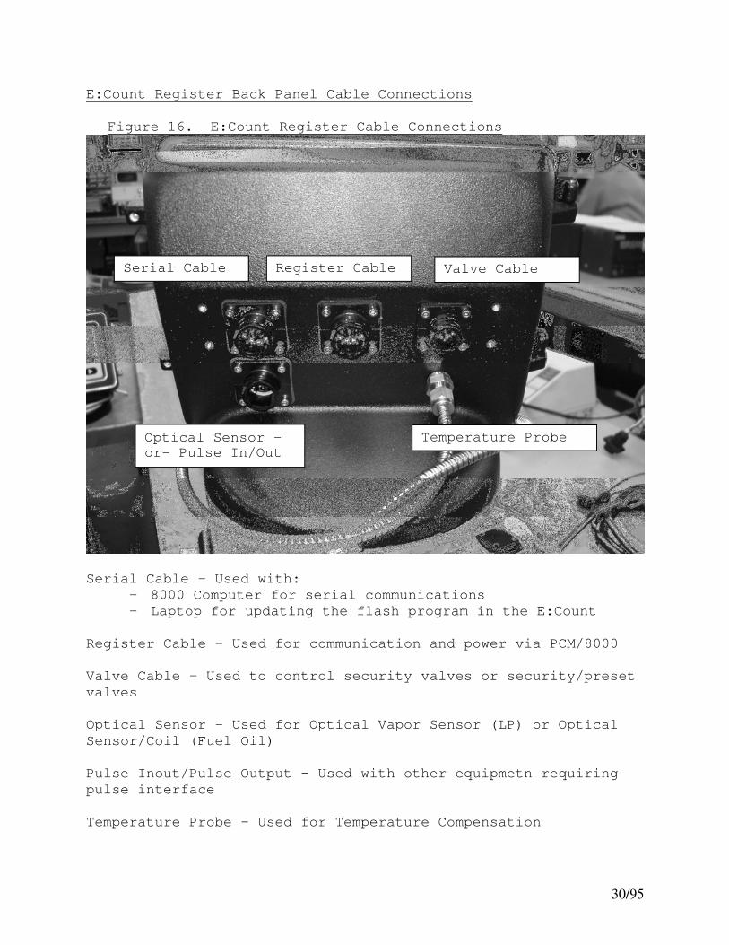
E:Count Register Back Panel Cable Connections
Figure 16. E:Count Register Cable Connections
Serial Cable - Used with:
- 8000 Computer for serial communications
- Laptop for updating the flash program in the E:Count
Register Cable – Used for communication and power via PCM/8000
Valve Cable – Used to control security valves or security/preset
valves
Optical Sensor – Used for Optical Vapor Sensor (LP) or Optical
Sensor/Coil (Fuel Oil)
Pulse Inout/Pulse Output – Used with other equipmetn requiring
pulse interface
Temperature Probe – Used for Temperature Compensation
Serial Cable
Optical Sensor –or- Pulse In/Out
Register Cable Valve Cable
Temperature Probe

31/95
E:Count ‘Computer’ Wiring Harness Connection
Depending on whether the E:Count is used as a Stand Alone
register or if it is used with an 8000 Computer, the “Computer”
wiring harness in the E:Count will be connected to a different
location.
Figure 17. E:Count Computer Wiring Harness Connection
Notice that there is a label on the connectors:
- “8000” is used when connecting the 8000 Computer
- “SLS/PC” is used for Stand Alone operation
The above Register is configured for Stand Alone Operation.
Stand Alone
8000

32/95
Section 4 – FIRMWARE VERSIONS AND COMMAND REFERENCE
Firmware Versions
ECount: E:Count Model # MCR-05
LT: E:Count LT Model # MCR-09
New Version Numbers as of September 2013:
ECount: E179E0, E179F0, E179S0
LT: L412E1, L412F1, L412S1
L412E2, L412F2, L412S2
E 179 E 0 PRODUCT VERSION LANGUAGE COMPENSATION TABLE E = ECount 3-Digits E=English 0 = All Tables 1-9
L = ECount LT F=French 1 = Propane Only
S=Spanish 2 = Fuel Oil/Diesel
Previous Version Numbers:
ECount English E178F
ECount French F178F
ECount Spanish S178F
LT English LT411C
LT French LF411C
LT Spanish LS411C

33/95
Figure 18. E:Count Quick Command Reference E179
PRSESET PRSESET MONEY MODE
AMOUNT MODE --> MONEY PRICE FRXXXX
▲▼◄► ▲▼◄► ▲▼◄►
HOSEPK OK *** PRICE ▲▼◄► MID:COM E:Count
PRCODE ▲▼◄► TAX 1 ▲▼◄► Menu Guide
QOB ▲▼◄► TXTYP1 ▲▼ Version: E179E0 English
MONEY currency menu *** TAX 2 ▲▼◄►
TIMOVR ▲▼ *** TXTYP2 ▲▼
SHIFT print shift report TAXSUB ▲▼ Press & Hold keys until the desired item is show n
DRIVER ▲▼◄► DISCNT ▲▼◄► or until the desired action is taken.
TOTAL ◄► DSCTYP ▲▼
DISVOL ▲▼ DSCDAY ▲▼◄► Press & Hold <MODE> to cycle through
TEMP F PRCADJ ▲▼◄►, ▲▼ Menu Items.
TEMP C EXIT delivery mode
CALTKT print cal report Press & Hold <START/STOP> to select the
SETUP setup menu Menu Item for display and update.
EXIT delivery mode
PRCODE ▲▼◄► Press & Hold <START/STOP> again to return to
DISVOL ▲▼ the Menu Item selection.
ATOCAL ▲▼◄►
NEWCOD ▲▼◄► CALFAC ▲▼◄► Press & Hold <RIGHT ARROW> on Menu Items
STAGE1 ▲▼◄► TEMP F ▲▼ to skip to EXIT.
STAGE2 ▲▼◄► TEMP C ▲▼
TIME ▲▼◄► TABLE# value at temp Press & Hold <LEFT ARROW> on Deliver Menu
DATE ▲▼◄► MRATIO ▲▼◄► to skip to SETUP.
SALE ▲▼◄► CMPTBL ▲▼◄►
TRUCK ▲▼◄► SERIAL ▲▼◄► Press & Hold <LEFT ARROW> on Setup Menu
CURNCY ▼ TIMER ▲▼ to skip to PRINTR.
PS RQD ▲▼ REGNUM ▲▼◄►
PRINTR ▼ U TYPE ▲▼ Press & Hold <LEFT ARROW> on Calibrate Menu
COPIES ▲▼◄► UNITS ▲▼ to skip to REGNUM.
HOSEPK ▲▼ PGROSS ▼
SS RST ▼ DECMAL ▲▼
6501PF ▲▼ AIRSEN ▲▼
HOSTFX ▼ PROBE ▲▼ *** Displayed depending on configuration.
KEYSON ▼ BRKVLV ▲▼
EXIT delivery mode DEMO ▲▼
EXIT calibration mode
Press MODE to set preset on Dollars
January 16, 2014
Delivery Menu
Setup Menu
PRESS MODE BUTTON TO ACCESS MENUS WHEN NOT IN DELIVERY
Currency Menu
Calibration Menu
PRESS PRESET BUTTON TO CHANGE PRESS MODE BUTTON TO DISPLAY
FLOW RATE DURING DELIVERY
Delivery Mode - In Delivery
Rate = xxxx units/minute
Delivery Mode - In Delivery
PRESS RIGHT-ARROW BUTTON TO
CHANGE PRICE DURING DELIVERYPRESET BEFORE / DURING DELIVERY
Delivery Mode - In Delivery

34/95
Figure 19. E:Count Quick Command Reference E180
PRSESET MODE
AMOUNT FRXXXX
▲▼◄►
HOSEPK OK *** PRCODE ▲▼◄► MID:COM E:Count
PRCODE ▲▼◄► DISVOL ▲▼ Menu Guide
QOB ▲▼◄► *** ATOCAL ▲▼◄► Version: E180E0 English
TIMOVR ▲▼ *** CALFAC ▲▼◄►
SHIFT print shift report MPCAL ▲▼◄►
DRIVER ▲▼◄► TEMP F ▲▼ Press & Hold keys until the desired item is show n
TOTAL ◄► TEMP C ▲▼ or until the desired action is taken.
DISVOL ▲▼ TABLE# value at temp
TEMP F MRATIO ▲▼◄► Press & Hold <MODE> to cycle through
TEMP C PLSREV ▲▼ Menu Items.
CALTKT print cal report CHANNL ▲▼
SETUP setup menu FLODIR ▲▼ Press & Hold <START/STOP> to select the
EXIT delivery mode CMPTBL ▲▼◄► Menu Item for display and update.
SERIAL ▲▼◄►
TIMER ▲▼ Press & Hold <START/STOP> again to return to
NEWCOD ▲▼◄► REGNUM ▲▼◄► the Menu Item selection.
STAGE1 ▲▼◄► U TYPE ▲▼
STAGE2 ▲▼◄► UNITS ▲▼ Press & Hold <RIGHT ARROW> on Menu Items
TIME ▲▼◄► PGROSS ▼ to skip to EXIT.
DATE ▲▼◄► DECMAL ▲▼
SALE ▲▼◄► AIRSEN ▲▼ Press & Hold <LEFT ARROW> on Deliver Menu
TRUCK ▲▼◄► PROBE ▲▼ to skip to SETUP.
REGNUM ▲▼◄► BRKVLV ▲▼
PRINTR ▲▼ DEMO ▲▼ Press & Hold <LEFT ARROW> on Setup Menu
COPIES ▲▼◄► *** EXIT calibration mode to skip to PRINTR.
LOGOHT ▲▼◄► ***
SS KEY ▲▼ Press & Hold <LEFT ARROW> on Calibrate Menu
EMULAT ▲▼ to skip to REGNUM.
QOB MD ▲▼
SWAUTH ▲▼
HOSTFX ▲▼
PKEYS ▼ *** Displayed depending on configuration.
HOSEPK ▲▼
EXIT delivery mode
PRESS PRESET BUTTON TO CHANGE PRESS MODE BUTTON TO DISPLAY
FLOW RATE DURING DELIVERY
Delivery Mode - In Delivery
Rate = xxxx units/minute
PRESET BEFORE / DURING DELIVERY
Delivery Mode - In Delivery
Setup Menu
September 16, 2015
Delivery Menu
PRESS MODE BUTTON TO ACCESS MENUS WHEN NOT IN DELIVERY
Calibration Menu

35/95
Section 5 - OPERATION
E:Count Overview and Theory of Operation
Meter Calibration and Temperature Compensation
The MID:COM E:Count model MCR-05 and E:Count LT model MCR-09 are
a general purpose electronic meter register for use with
mechanical positive displacement meter with rotational output as
well as other types of meters with electronic pulse outputs. In
the case of a rotational output, the E:Count has an internal 100
pulse per revolution (ppr) quadrature encoder which converts the
meter rotation to a pulse train. Meter calibration and optional
temperature compensation techniques are all-digital in nature
and are explained below.
Meter Calibration (Un-compensated)
Meter calibration is a two-step process. First a prescale factor
called MRATIO must be determined and entered. This number is an
integer value from 1 to 99 and only needs to be entered when the
E:Count is initially installed.
This factor serves three purposes:
1. It allows the resulting calibration factor to remain just
above or below unity which preserves the "1 part in 10,000"
calibration resolution. For example, if there were 10 times
too many pulses per unit volume the calibration factor would
be near 0.1. This would result in the least significant digit
of the calibration factor representing 1 part in 1000.
2. It allows for the elimination of mechanical adjusters and gear reductions which can add torque to the meter as well as wear
out and slip.
3. It allows for a convenient way to change units of measure such as: gallons, liters, kilograms, etc.
This factor can be determined by trial and error or by
contacting MID:COM with the following information:
1. Meter manufacturer. 2. Meter size. 3. Units of measure.
The second step in calibration, and only step after initial
installation, is to determine the calibration factor with a
prover or master meter. For initial installation a factor
of 1.0000 should be used as a point of reference. Subsequently
use the present factor.

36/95
E:Count Overview (continued)
With a calibration factor near unity, the meter error as
expressed by PROVER VOLUME/REGISTER VOLUME results in a
percentage in which the error can be added or subtracted to the
current calibration factor as needed.
Another way to view the factor is that the digits to the right
of the decimal represent the following:
• First digit - tens of units/hundred units
• Second digit - units/hundred units
• Third digit - tenths of units/hundred units
• Fourth digit - hundredths of units/hundred units.
The calibration factor represents the value of each pulse as it
is received by the E:Count. These are added to each other and
the resultant sum is compared to the volume currently displayed.
If the new rounded value is greater than the current displayed
value the displayed value is adjusted accordingly.
Temperature Compensation
Temperature compensation is done by table lookup only. The
E:Count is loaded with the appropriate API or ASTM table for the
following products:
Comp Table # Description
------------ -----------
00 UNCOMPENSATED
01 PROPANE
02 DIESEL/HEATING OIL
03 GASOLINE
04 LUBE OIL
05 METHANOL
06 ANHYDROUS AMMONIA OR AVIATION GASOLINE
07 JET-A FUEL
08 JET-B FUEL
09 ETHANOL
The tables are interpolated and extrapolated as necessary to
have 1024 entries ranging from -40 to +62.4 degrees Celsius in
0.1 degree steps. As each pulse is received the temperature is
sampled and the corresponding table entry for that temperature
is multiplied by the calibration factor. The result is added,
rounded and displayed as described above, but as a separate
value.

37/95
E:Count Overview (continued)
Thus, there is always a running count of uncompensated AND
compensated volumes. After the delivery these values can be
toggled on the display to facilitate computations without the
need to run BOTH compensated and uncompensated tests.
Both the current temperature and its associated table value
can be displayed. If adjustment is necessary for the net
volume, the temperature is adjusted up or down to obtain the
table value necessary for the next test to be accurate.
It can occur that when an accurate test is obtained, the
displayed temperature is not the same as the test thermometer
temperature. There can always be small discrepancies since
the temperature can vary during the delivery and the
displayed temperature is what the product is at after the
delivery.
However, if the difference is large the following needs to be
considered:
1. The displayed temperature will always correspond to the correct table value.
2. The resulting calculations using that value will also always be correct.
3. The table in the E:Count may not be the same as the one being used for the test.
4. The product being tested is not exactly the same as what the table is intended for.
The fourth item is the most common source of error especially
in the case of propane. In the summer months it is quite
common for refiners to blend in other products with higher or
lower coefficients of expansion thus skewing the test.
There is no inherent problem with adjusting the temperature
to make the test come out correctly, however if the product
changes later on, the system may go out of tolerance. This
situation has come up so often that it is necessary to
emphasize that the compensator may be working as designed and
consideration should be given to other factors affecting the
test.

38/95
E:Count Overview (continued)
Product Codes
The E:Count MCR-05 is able to handle 99 different product
codes. Each product code defines:
1. Product identifier (i.e. PROPANE) which is printed on the delivery ticket.
2. Calibration factor for the product. 3. Compensator status (on/off) for the product. 4. Assigned compensator table for the product. 5. Preset valve second stage dwell.
The product code must be selected in Delivery Mode before a
delivery is started. All settings made in any mode are
stored associated with the current product code.
[MCR-09 LT: The E:Count LT is preprogrammed at the factory
with one (1) product code.]

39/95
Electronic Air Sensor
The AIRSEN Menu Item in the Calibration Menu is an ON/OFF
toggle.
If an Electronic Air Eliminator is connected to the E:Count
the AIRSEN feature needs to be turned on. If the AIRSEN
feature is Enabled and the Sensor is not connected the outlet
valves will never open.
During the delivery process, if the optical sensor sees air
the E:Count will close the outlet solenoid valves and
simultaneously open the air release solenoid. When the
optical sensor sees liquid the reverse occurs unless the
outlet valves were previously closed by either a Preset or by
the START/STOP key, in which case only the air solenoid will
close.
Outside of delivery mode the air solenoid is off or closed.
MCR-09 LT AIRSEN Reference – LT Air Sensor Functions
The AIRSEN menu item in the LT is not available in versions
prior to L413.
LT (MCR-09) AIRSEN CONNECTIONS
Air Solenoid:
J9-3 RELAY1/AIRSOL
J9-5/6 GROUND
Optic Sensor:
J3-2 +5 VDC (RED)
J1-5 SIGNAL (WHITE)
J1-6 GROUND (BLACK)
Mechanical Switch: The Optic input is active LOW when liquid
J1-5 SIGNAL is present. The switch should be wired
J1-6 GROUND so that it is closed when liquid is
present or the float is high.
MCR-09 LT AIRSEN, HOSSEL, AUTHRX IMPORTANT NOTE
AIRSEN is implemented in all LT versions starting with L413.
If AIRSEN is ON then neither HOSSEL (Hose Selection) *nor*
AUTHRX (Host Authorization) can be enabled. Conversely, if
either HOSSEL or AUTHRX is ON then AIRSEN cannot be enabled.
“NOGOOD” will be displayed when an attempt is made to
configure the LT as such in either case.
40/95
Flow Rate
While delivering product, the <MODE> key may be pressed
during pumping to show flow rate.
The flow rate will display “FRxxxx” for one second and then
normal counting will resume.
A minimum of 6 seconds of product flowing is required for the
flow rate to display.
If fewer than 6 seconds have elapsed since the previous flow
rate display, the display will simply hesitate for one second
and resume normal counting.
Mass or Volume
The “U TYPE” setting in the Calibration Menu controls whether
Mass in POUNDS/KILOS or Volume in GALLONS/LITRES are
delivered.
All tickets will display the units based on the selected Unit
Type and Units settings.
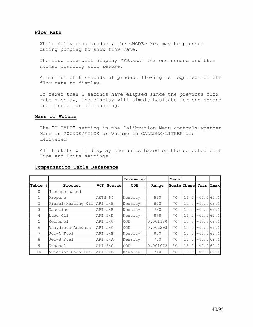
Compensation Table Reference
Parameter Temp
Table # Product VCF Source COE Range Scale Tbase Tmin Tmax
0 Uncompensated
1 Propane ASTM 54 Density 510 °C 15.0 -40.0 62.4
2 Diesel/Heating Oil API 54B Density 840 °C 15.0 -40.0 62.4
3 Gasoline API 54B Density 730 °C 15.0 -40.0 62.4
4 Lube Oil API 54D Density 878 °C 15.0 -40.0 62.4
5 Methanol API 54C COE 0.001180 °C 15.0 -40.0 62.4
6 Anhydrous Ammonia API 54C COE 0.002293 °C 15.0 -40.0 62.4
7 Jet-A Fuel API 54B Density 800 °C 15.0 -40.0 62.4
8 Jet-B Fuel API 54A Density 760 °C 15.0 -40.0 62.4
9 Ethanol API 54C COE 0.001072 °C 15.0 -40.0 62.4
10 Aviation Gasoline API 54B Density 710 °C 15.0 -40.0 62.4

41/95
Power Latching
“Power Latching” refers to the ability of the E:Count to tell
the PCM to not power off during a delivery.
Normally, a PCM is installed with both switched and
unswitched +12VDC connected to it. When the key is turned on
the PCM senses this and powers on all equipment connected to
it.
Similarly, when the PCM detects that the ignition has been
turned off, it will turn off the power to all equipment.
During a delivery, the E:Count instructs the PCM to *not*
power off, thereby preventing an ignition event (or some
unknown condition) from prematurely ending a delivery. Once
the delivery is over the E:Count resumes the PCM normal power
monitoring.
Power Failure
In the Event that a Delivery is interrupted by a Power
Failure (whether due to vehicle hardware failure, accidental
causes, or malfeasance), upon rebooting the E:Count will
detect and indicate that an error has occurred.
The Meter Block for the interrupted delivery must be printed
before the register may be used again.
Upon rebooting after a Power Failure During a Delivery the
E:Count register will display ERROR PRESS PRINT until any of
the 8 keys on the E:Count are pressed.
In a configuration with multiple registers connected to a
single printer this sequence allows the operator to control
when each register prints, as well as preventing multiple
printers from automatically printing at the same time.
The E:Count will next verify that the configured printer has
paper, and should it be necessary the E:Count will indicate
that paper must be loaded to continue.
The E:Count then finalizes and prints the delivery Meter
Block for the interrupted delivery, and finishes
initializing.
***** POWER FAILURE ***** will print on the Meter Block.

42/95
Power Failure During a Host Mode Delivery
In the Event that a Host Mode Delivery is interrupted by a
Power Failure, the following also applies:
The E:Count will not respond to the Host until the
interrupted Meter Block is printed.
The Host may interrogate the delivery data for the proceeding
delivery at any time, and the E:Count will indicate in the
Delivery Status data that Power was interrupted during the
delivery.
The Host will not be allowed to print before or after the
Meter Block is printed – the delivery will be ended just as
if it was a Pump & Print delivery.
See the E:Count Host Interface Guide for more information.

43/95
Display Microprocessor - Errors and Detection
As of software version E164E, the E:Count will detect that
the Display Microprocessor has the correct firmware.
If the Display Microprocessor contains an incompatible
software version an error message will be displayed.
Depending on the error message, the software for either or
both the Display Micro and the Main Micro in the E:Count must
be updated.
To verify the error, cycle the power twice and make sure the
same error message is repeated. If the error goes away then
it was a synchronization problem due to programming, and no
changes are necessary.
NEW DM 1. Displayed: After programming with FILL 0.
CYCLE To Fix: Cycle power as indicated.
POWER 2. Displayed: When DM contains DM11 (or
newer) and the E:Count software is E163E
(or older).
To Fix: Load E:Count software E164E (or
newer) – or – if using old version of
E:Count software is required then an
old DM version must be loaded (such as
DM4). Contact the Factory for assistance.
DMICRO 1. Displayed: After programming with FILL 0.
ERROR To Fix: Cycle power as indicated.
CYCLE 2. Displayed: When DM contains DM10 (or
POWER older) and the E:Count software is E164E
(or newer).
To Fix: Contact the factory for a DM11
(or newer) chip.
In order to use version E164E (or newer) of the E:Count
software on an *existing* E:Count, the "Display Micro" chip
inside the E:Count must be upgraded to version DM11. All
previous versions of the Display Micro are incompatible with
E:Count version E164E and higher. DM11 will not work in an
E:Count with E163E (or older), *also* DM10 will not work in
an E:Count with E164E (or newer).
44/95
HostFix
The HostFix E:Count setting (HOSTFX in the Setup Menu)
requires Host commands send a prefix character intended to
prevent stray serial characters from being interpreted as
commands. Use the <DOWN> arrow to cycle through the available
settings.
Added in E:Count version E175F.
Software Updates/Versions Required (If Enabled):
o MATRIX, ALL ...: Matrix version 2.0.0.523 (or newer).
o MATRIX, ALL ...: RoadWarrior version 3.0.35.447 (or newer).
o All ...........: Updated Host software, contact vendor.
Settings:
o OFF HOSTFX OFF Prefix not required.– DEFAULT.
o MATRIX HOSTFX MATRIX Require only ‘Matrix’ commands to
use a prefix character. This setting requires
updated Matrix software.
o ALL HOSTFX ALL Requires all host software commands to
use a prefix character. This setting requires
updated Matrix software *and* updated Host
software. Contact your Host software provider
for more information.
Compatibility:
E:Count HostFix Software Compatibility
--------------------------------------------------------
E174/older N/A All Host Versions Compatible.
E175(+) “OFF” All Host Versions Compatible.
E175(+) “MATRIX” Requires Matrix 2.0.0.524(+).
All Host Versions Compatible.
E175(+) “ALL” Requires Matrix 2.0.0.524(+).
RoadWarrior 3.0.35.447(+).
Requires Updated Host Software!

45/95
Section 6 – REQUIRED E:COUNT CONFIGURATION SETTINGS
Below are the Minimum Required Settings for the end-user to
setup an E:Count “out of the box”.
Calibration Menu:
PRCODE – Current Product Code
CALFAC – Calibration Factor (per product)
MPCAL - Muiltipoint Calibration setting
MRATIO – Meter Ratio
PSLREV - Encoder Pulses per Revolution
CHANNL - Single or Dual Channel Encoder
FLODIR - Clockwise or Counter-Clockwise Flow Direction
CMPTBL – Compensation Table Number (per product)
SERIAL – Register Serial Number
TIMER – No Flow Timeout setting
REGNUM – Register Port Number
U TYPE – Mass or Volume
UNITS – Units, either Gallons or Litres
PGROSS – Print Gross Volume setting
DECMAL - Decimal Settings
AIRSEN - Air Sensor Status
PROBE - RTD or Analog (RTD replaces Analog as of June 2007)
BRKVLV - Broken Valve to Detect Flow Outside of a Delivery
DELIVERY MENU
DRIVER – Driver Number
SETUP MENU
NEWCOD - Note the Existing Security Code
STAGE1 - Stage 1 Fast Flow Shutoff Value
STAGE2 - Stage 2 Slow Flow Dwell Value (per product)
SALE - Next Sale Number
TRUCK - System Truck Number
CURNCY – Currency Display setting
PRINTR - Printer Type
COPIES - Number of Thermal Printer Copies (if necessary)
HOSEPK - Enable Hose Packing (if necessary)
SS RST - Disable Pump & Print (if necessary)
6501PF - MID:COM 6501 Print Format (if necessary)
HOSTFX - Host Fix to require Prefix Characters (if necessary)
EMULAT - Host Emulation for other Firmware Versions
SWAUTH - Software Authorization for Host Control

46/95
Section 7 - MODES
Delivery Mode
To enter Calibration Mode back out the <CALIBRATION SCREW>.
CALBRT MODE will be shown and the E:Count will enter
Calibration Mode.
To enter Program Mode back out the <PROGRAM SCREW> and the
E:Count will automatically enter Program Mode.
[MCR-09 LT: Program Mode Not Available.]
To Set the Preset Volume press <PRESET>. PRESET will be shown
and allow the Preset Volume to be modified.
To Begin a Delivery insert a ticket into the printer and press
<START/STOP>; DELIVR will be shown, the E:Count will reset to
00000.0, and the Security Valve will open allowing product to
be dispensed.
To enter the Delivery Menu press <MODE> and PRCODE will be
shown.
Figure 20. E:Count Delivery Process

47/95
Delivery Mode (continued)
1. Press <PRESET> to enable the Preset and set the Preset Volume.
a. Press the <ARROW> keys to modify the current Preset Volume.
b. Press <MODE> to enter the Preset on Dollars.
• Press <START/STOP> to save the Preset on Dollars
c. Press the <START/STOP> key to save the Preset Volume and enable the Preset for the next delivery.
[MCR-09 LT: Preset is Optional]
2. Press <START/STOP> to Begin a Delivery and Open the Security Valve.
a. If a ticket is in the printer DELIVR will be displayed and VALVES OPEN will be displayed.
b. The Security Valve will open and the display elements will reset (all on followed by all off).
c. If no ticket is in the printer INSERT TICKET will be displayed - the E:Count will not begin a delivery until
a ticket is inserted into the printer.
3. Deliver Product.
4. Press <PRESET> to enable another Preset and set a Preset Volume for the next Delivery Segment.
a. Press the <ARROW> keys to modify the Preset Volume for the next Delivery Segment.
b. Press <MODE> to enter the Preset on Dollars.
• Press <START/STOP> to save the Preset on Dollars
c. Press the <START/STOP> key to save the Preset Volume and enable the next Preset Volume for the next Delivery
Segment.
5. Press <MODE> to edit the current Product Price (added in version E138E.
6. Press <PRINT> to finalize and end the delivery. a. VALVES CLOSED will be shown and the Fuel Delivery
Ticket will print.
b. The Delivered Volume will remain on the display.
Note: <START/STOP> functions as an <EMERGENCY STOP> button
while product is flowing. After an <EMERGENCY STOP> the
Security Valve will be closed. The Fuel Delivery Report
will not print until <PRINT> is pressed.

48/95
Hose Packing
To Enable the Hose Packing feature of the E:Count, turn the
Hose Pack item (HOSEPK) in the Setup Menu to ON.
Hose Packing is intended to allow the operator to pressurize
the hose as needed.
Per Weights and Measures specifications up to 1.0 Gallon or 0.3
Litres may be pumped into the hose to Pack the Hose before or
after the delivery.
Selecting HOSEPK on the Delivery Menu will cause the E:Count to
open the Stage 2 (slow flow) valve.
If less than 1.0 Gallon or 0.3 Litres are pumped during a Hose
Pack operation the E:Count will automatically discard that
volume; it will not be added to either a delivery volume or a
shift volume.
If more than 1.0 Gallon or 0.3 Litres are pumped during a Hose
Pack operation the E:Count will automatically reset and begin a
delivery at the accumulated volume, 1.1 Gallons or 0.4 Litres
respectively.
Broken Valve Detection
The E:Count will automatically reset and begin a delivery if
either of the valves fail (or if either of them are incorrectly
installed) and product is allowed to flow outside of a
delivery.

49/95
Preset Operation
[MCR-09 LT: Preset Is Optional]
The preset function works differently depending on whether the
preset amount is entered before the delivery, and/or during the
delivery.
"Before the Delivery" is defined as any time a delivery is not
active, and continues until the register is reset to begin a
delivery. "During the Delivery" is defined as the time
between pushing the <START/STOP> button to start a delivery and
the meter ticket being printed.
Preset Before the Delivery:
• The preset amount may be entered any number of times.
• The last entry is saved as the "TARGET" preset amount.
• A volume of zero (00000.0) means no preset for the
delivery, any amount may be delivered.
Each time the <PRESET> button is pressed to enter an amount the
last amount entered before the start of the delivery will be
displayed. This is true for entries made during deliveries and
also on subsequent deliveries. This feature facilitates
batching situations. The one exception to this is if the "PRESET
REQUIRED" option has been turned on in SETUP. If so the default
amount displayed is always zero.
Preset During the Delivery:
• Multiple presets are allowed during the delivery.
• Preset entries made during a delivery are additive in
nature. The amount entered is added to the original TARGET
amount to create a new Preset TARGET amount.
o Example:
o Original preset amount of 80 gallons is delivered and
the valves will shut.
o The user wants to deliver 20 more gallons and
therefore 20 is entered for the next preset.
o The E:Count does the math to correctly set the new
Target at 100 gallons.
o Each time a new entry is made the TARGET increases by
that amount.
• Note: A new preset amount cannot be entered until the last
preset is reached. If an attempt to do so is made the
E:Count will display "PRESET ACTIVE" and return back to the
delivery.

50/95
No Preset Entered Before the Delivery
A preset amount may be entered during a delivery even if no
preset amount was entered before the delivery. The amount
entered should be the total amount to be delivered since the
E:Count is using zero as the "original preset", for the "no
preset" delivery. Note: If the amount entered is less than
what has already been delivered the E:Count will shut the
preset valve immediately on resuming the delivery.
Note: If a situation occurs that the delivery has started and
the preset amount is incorrect, the procedure would be to print
the ticket at the current amount and start over with the
correct preset amount.
Preset on Dollars
When <PRESET> is pressed the volume displayed will be the
current Preset Volume.
The <MODE> button may be pressed to switch to MONEY.
Use the Arrow keys to modify the Preset on Dollars Amount.
Press <START/STOP> to save the target Preset on Dollars Amount.
The equivalent Preset Volume required based on the current
pricing will be calculated and shown, allowing the new Preset
Volume to be modified if necessary.
The Preset Volume is 'saved' when the <START/STOP> button is
pressed.
Batch Mode Preset (E179 Rev3 and earlier)
When Batch Mode is ON the Preset Volume is saved both between
deliveries and when the E:Count is powered off. Every
delivery performed during Batch Mode use the existing Preset
Volume, which may only be modified before the delivery.
During a Batch Mode delivery both pressing <START/STOP> *and*
reaching the Preset Volume will end the delivery and print the
Meter Ticket.
The Host Mode Preset and Host Mode Reset functions are *not
valid* when Batch Mode is ON.

51/95
Multiple Presets in a Single Delivery
The MID:COM E:Count is capable of Multiple Presets. The
following is an example of a blending delivery:
1. Press <PRESET> to enter the Preset Screen a. Use the <ARROW> keys to set the initial Preset Volume b. Press <START/STOP> on the Preset Screen to save the
initial Preset Volume
2. Press <START/STOP> to open the security valves and begin the delivery
a. When the Preset Volume is reached the valves will close 3. Press <PRESET> to enter the Preset Screen
a. Use the <ARROW> keys to set the next Preset Volume b. Press <START/STOP> on the Preset Screen to save the
next Preset Volume
4. Press <START/STOP> to open the security valves and continue the delivery
a. When the Preset Volume is reached the valves will close.
At the beginning of each delivery the Preset Volume is 0 unless
a Preset is entered using the <PRESET> key. When <PRESET> is
pressed during the delivery the previous Preset Volume value
will be displayed. The Preset Volume is 'saved' when the
<START/STOP> button is pressed.
During the delivery the Preset Volume is an additive field, not
an absolute value. That is, each time the <START/STOP> button
is pressed (to save the Preset Volume) the New Preset Target is
the total of the Preset Volumes that have been entered during
the delivery.
Example: A delivery of 100 units of 80%/20% diesel/kerosene
Blending is used primarily for preventing diesel from freezing
during cold weather. The initial Preset Volume would be 80
(for 80 units of diesel). After delivering 80 units the valves
close automatically. The operator would next set the Preset
Volume to 20 (which indicates that the E:Count should add 20
additional units to the Preset Target). After delivering the
20 units of kerosene (yielding a 20% blend) the valves will
again close automatically.
The additive method of multiple presets is intended to prevent
the operator from having to do math. He simply sets the next
Preset Volume to be the volume of the product to be delivered.

52/95
Editing Product Price During (or After) Delivery
With Currency enabled, pressing the <RIGHT ARROW> button during
the delivery while product is not flowing will display the
price for the Current Product and allow it to be changed.
If Currency is disabled, pressing the <RIGHT ARROW> during the
delivery will *not* display the price.
The price may be changed up until the actual delivery Meter
Block is printed.
Multiple Product Price Adjustment
The price of all valid products may be adjusted by a specific
amount using the PRCADJ command on the MONEY Menu.
The price(s) will be increased (ADD) or decreased (SUB)
depending on the selection.
When <START/STOP> is selected on PRCADJ, a price adjustment
amount may be entered.
After entering the price adjustment amount, pressing
<START/STOP> will display ADD. Press <UP> to select ADD or
<DOWN> to select SUB (or subtract).
After selecting ADD or SUB, press <START/STOP> to force the
adjustment on all prices.

53/95
Delivery Menu
Delivery Menu Categories
HOSEPK – Enable Hose Pack – Open Stage 2 Valve
PRCODE – Display or Change the Active Product Code
QOB – Display or Change the Quantity On Board
MONEY - Enter Currency Mode (179 and older)
TIMOVR – Display or Change the Flow Timer Override
SHIFT – End the Shift and Print the Shift Report
DRIVER – Display or Change the Driver Number
TOTAL – Display the Totalizer
DISVOL – Display the Gross and Net Delivery Volumes
TEMP F – Display the current Product Temp in Degrees F
TEMP C - Display the current Product Temp in Degrees C
CALTKT – Print a Calibration Ticket
SETUP – Enter the Setup Menu
EXIT - Return to Delivery Mode
When entering the Delivery Menu the E:Count will display the
current Delivery Menu Category.
To display the next Delivery Menu Category press <MODE>.
To view or modify the Delivery Menu Category press
<START/STOP>.
To exit the Delivery Menu and return to Delivery Mode press and
hold <MODE>, or press and hold <RIGHT ARROW> to display EXIT,
and then press <START/STOP>.
To enter Setup Mode:
1. Press and hold <MODE> until SETUP is displayed in the Delivery Menu
2. Press <START/STOP> a. The E:Count will display ENTER CODE.
3. Enter the Security Code and press <START/STOP>. a. If the Security Code is correct OK will be displayed
and the E:Count will enter Setup Mode.
b. If the Security Code entered is NOT correct NOGOOD will be displayed and the E:Count will return to Delivery
Mode.
Note: The factory default Security Code is 000000.
54/95
Delivery Menu (continued)
Delivery Menu Categories
HOSEPK – Open Valve to Pack the Hose
Press <START/STOP> to Open Stage 2 (Slow Flow) Valve to
Pressurize Hose.
PRCODE – Product Code
Press <START/STOP> to set the current Product Code.
The Product Code is a 2-digit number from 00 to 99.
Use the <ARROW> keys to change the Product Code.
Press <START/STOP> to save the Product Code and return to
Delivery Mode.
Note on Product Code:
Changing the Product Code affects all calibration data.
The Calibration Factor, Temperature Compensation Setting
(enabled or disabled), and the Stage 2 Dwell are all
stored separately for each Product Code. Changing the
Product Code will load the saved value for each of these
variables.
QOB – Quantity on Board
Press <START/STOP> to display or set the Quantity on Board
for the current Product Code.
The Quantity on Board is a 6-digit number from 00000.0 to
99999.9.
Use the <ARROW> keys to change the Quantity on Board.
Press <START/STOP> to save the Quantity on Board and return
to Delivery Mode.
MONEY – Currency Mode
Press <START/STOP> to enter Currency Mode.
The E:Count will display the Currency Menu.

55/95
Delivery Menu (continued)
TIMOVR – No Flow Timer Override
Press <START/STOP> to display the current Timer Override
setting.
Press <UP> to disable the No Flow Timer for the Next
Delivery (Timer Override is ON). The message “MULTIPLE
TANK DELIVERY AT ONE SITE ONLY” will print on the delivery
ticket. The Timer will automatically be enabled at the
start of the next delivery.
Press <DOWN> to enable the No Flow Timer for the Next
Delivery (Timer Override is Off).
The TIMOVR default value at the beginning of each delivery
is OFF.
Press <START/STOP> to save the Timer Override and return to
Delivery Mode.
Note on Timer Override:
If the TIMER setting in the Calibration Menu is OFF, the
TIMOVR menu item will not be shown.
SHIFT – Shift Report
Press <START/STOP> to print the current Shift Report.
The E:Count will return to Delivery Mode automatically when
Shift Report printing is complete.
DRIVER – Driver Code
Press <START/STOP> to set the current Driver code.
The Driver code is a 4-digit number from 0000 to 9999.
Use the <ARROW> keys to change the Driver code.
Press <START/STOP> to save the Driver code and return to
Delivery Mode.
TOTAL – Totalizer
Press <START/STOP> to display the Current Totalizer.
The Net Totalizer will be displayed if Temperature
Compensation is enabled – OR - the Gross Totalizer will be
displayed if temperature compensation is disabled.
The Totalizer display requires two screens to show all of
the Totalizer data; initially only the right-most 5 digits
and the tenths will be displayed.
To view the left Totalizer digits press the <LEFT ARROW>.
To view the right Totalizer digits press the <RIGHT ARROW>.
Press <START/STOP> to exit the Totalizer and return to
Delivery Mode.

56/95
Delivery Menu (continued)
DISVOL – Volumes
Press <START/STOP> to display the Gross Volume or the Net
Volume of the previous delivery.
Press <UP> to display the Net Volume.
Press <DOWN> to display the Gross Volume.
Press <START/STOP> to return to Delivery Mode.
TEMP F – Current Product Temperature in Degrees F
Press <START/STOP> to display the Current Temperature.
The current Temperature in Degrees Fahrenheit will be
displayed (if the temperature probe is installed).
Press <START/STOP> to return to Delivery Mode.
TEMP C – Current Product Temperature in Degrees C
Press <START/STOP> to display the Current Temperature.
The current Temperature in Degrees Celsius will be
displayed (if the temperature probe is installed).
Press <START/STOP> to return to Delivery Mode.
CALTKT – Calibration Report
Press <START/STOP> to print the current Calibration Report.
The E:Count will return to Delivery Mode automatically when
Calibration Report printing is complete.
SETUP – Enter Setup Mode
Press <START/STOP> to enter Setup Mode.
ENTER CODE and then 000000 will be displayed and the
Security Code must be entered to continue.
Use the <ARROW> buttons to enter the current Security Code.
Press <START/STOP> to enter the Security Code and continue
in Setup Mode.
If the Security Code entered is correct the E:Count will
display OK and begin Setup Mode.
If the Security Code entered is incorrect the E:Count will
display NOGOOD and return to Delivery Mode.
Note: The factory default Security Code is 000000.
EXIT – Exit Delivery Menu
Press <START/STOP> to exit the Delivery Menu and return to
Delivery Mode.

57/95
Currency Mode
Currency Mode Categories:
PRICE - Display or Change the Price for the Current Product
TAX 1 - Display or Change the Tax 1 Rate
TXTYP1 - Display or Change the Tax 1 Type
TAX 2 - Display or Change the Tax 2 Rate
TXTYP2 - Display or Change the Tax 2 Type
TAXSUB - Display or Change ‘Tax 1 Subject to Tax 2’
DISCNT - Display or Change the Discount Rate
DSCTYP - Display or Change the Discount Type
DSCDAY - Display or Change the Discount Days
PRCADJ – Price Adjustment for all Valid Products
EXIT - Return to Delivery Mode
To display the next Currency Category press <MODE>.
To view or modify the Currency Category press <START/STOP>.
To exit Money Mode and return to Delivery Mode press and hold
<MODE> or press and hold <RIGHT ARROW> until the E:Count
displays EXIT and then press <START/STOP>.

58/95
Currency Mode (continued)
Currency Mode Categories
PRICE – Set the Price for the Current Product
Press <START/STOP> to set the Price.
The Price is a number from 0.0000 to $9.9999.
Use the <ARROW> keys to change the Price.
Press <START/STOP> to save the Price and return to Money
Mode.
TAX 1 – Set Tax 1 Rate
Press <START/STOP> to set the Tax 1 Rate.
The Tax 1 Rate is a number from 00.0000 to $9.9999 or
99.9999%.
Use the <ARROW> keys to change the Tax 1 Rate.
Press <START/STOP> to save the Tax 1 Rate and return to
Money Mode.
TXTYP1 – Set Tax 1 Type
Press <START/STOP> to set the Tax 1 Type.
The Tax 1 Type is either PERCNT or DOLLAR.
PERCNT will calculate the tax at the tax rate as a
percentage of the extension price.
DOLLAR will calculate the tax using the tax rate per
unit volume.
Use the <UP/DOWN ARROW> keys to change the Tax 1 Type.
Press <START/STOP> to save the Tax 1 Type and return to
Money Mode.
TAX 2 – Set Tax 2 Rate
Press <START/STOP> to set the Tax 2 Rate.
The Tax 2 Rate is a number from 00.0000 to $9.9999 or
99.9999%.
Use the <ARROW> keys to change the Tax 2 Rate.
Press <START/STOP> to save the Tax 2 Rate and return to
Money Mode.
59/95
Currency Mode (continued)
TXTYP2 – Set Tax 2 Type
Press <START/STOP> to set the Tax 2 Type.
The Tax 2 Type is either PERCNT or DOLLAR.
PERCNT will calculate the tax at the tax rate as a
percentage of the extension price.
DOLLAR will calculate the tax using the tax rate per
unit volume.
Use the <UP/DOWN ARROW> keys to change the Tax 2 Type.
Press <START/STOP> to save the Tax 2 Type and return to
Money Mode.
TAXSUB – Setup Subtotal Tax
Press <START/STOP> to set the Subtotal Tax, that is whether
Tax 1 is Subject to Tax 2.
The Subtotal Tax is either ON or OFF.
ON will calculate Tax 2 including Tax 1.
OFF will calculate Tax 2 excluding Tax 1.
Use the <UP/DOWN ARROW> keys to change the Subtotal Tax.
Press <START/STOP> to save the Subtotal Tax and return to
Money Mode.
DISCNT – Set the Discount Rate
Press <START/STOP> to set the Discount Rate.
The Discount Rate is a number from 00.0000 to $9.9999 or
99.9999%.
Use the <ARROW> keys to change the Discount Rate.
Press <START/STOP> to save the Discount Rate and return to
Money Mode.
DSCTYP – Set the Discount Type
Press <START/STOP> to set the Discount Type.
The Discount Type is either PERCNT or DOLLAR.
PERCNT Discount = (Discount Rate * Total Amount Due)
DOLLAR Discount = (Discount Rate * Volume Delivered)
Use the <UP/DOWN ARROW> keys to change the Discount Type.
Press <START/STOP> to save the Discount Type and return to
Money Mode.
Note: The Percent Discount is a “Bottom-Line” discount, all
charges are discounted. The Dollar Discount is a “Rebate”
discount, only the cost of the product is discounted.

60/95
Currency Mode (continued)
DSCDAY – Set the Discount Days
Press <START/STOP> to set the Discount Days.
The Discount Days is a number from 00 to 99.
The Discount Days will print on the Delivery Ticket and
inform the customer when they need to pay in order to
deduct the discount amount.
Use the <ARROW> keys to set the Discount Days.
Press <START/STOP> to save the Discount Days and return to
Money Mode.
PRCADJ – Adjust the price for all valid products
Press <START/STOP> to enter the amount of the Price
Adjustment.
The Price Adjustment is an amount from 0.0001 to 9.9999.
The Price Adjustment will be applied to all valid products.
Use the <ARROW> keys to set the Discount Days.
Press <START/STOP> to save the Price Adjustment, then press
<UP> to select ADD or press <DOWN> to select SUB (or
subtract). Press <START/STOP> to apply the Price Adjustment and return
to Money Mode.
EXIT – Exit Money Mode
Press <START/STOP> to exit Money Mode and return to
Delivery Mode.

61/95
Setup Mode
Setup Categories:
NEWCOD – Display or Change the Security Code
STAGE1 - Display or Change the Stage 1 Shutoff Value
STAGE2 - Display or Change the Stage 2 Dwell Value
TIME - Display or Change the E:Count System Time
DATE - Display or Change the E:Count System Date
SALE - Display or Change the Next Sale Number
TRUCK - Display or Change the System Truck Number
REGNUM – Display or Change the Active Register Number (180)
CURNCY - Display or Change the Currency Setting (179)
PS RQD - Display or Change the Preset Requirement (179)
PRINTR - Display or Change the Printer Type
COPIES - Display or Change the Number of Thermal Copies
HOSEPK - Display or Change the Hose Pack Setup
SS RST – Enable/Disable the Start/Stop Reset Function
6501PF – Enable/Disable the Midcom 6501 Print Format (179)
HOSTFX – Set the Host Command Prefix Requirement
BATCH – Display or Change the Batch Mode Setting (179)
EXIT - Return to Delivery Mode
When entering Setup Mode the E:Count will require the operator
to enter the Security Code to continue. After a valid Security
Code is entered the E:Count will display the first Setup
Category.
To display the next Setup Category press <MODE>.
To view or modify the Setup Category press <START/STOP>.
To exit Setup Mode and return to Delivery Mode press and hold
<MODE> or press and hold <RIGHT ARROW> until the E:Count
displays EXIT and then press <START/STOP>.
Note: The factory default Security Code is 000000.

62/95
Setup Mode (continued)
Setup Categories
NEWCOD – Set Security Code
Press <START/STOP> to set the Security Code.
The Security Code is 6 digits from 000000 to 999999.
Use the <ARROW> keys to change the Security Code.
Press <START/STOP> to save the Security Code and return to
Setup Mode.
STAGE1 – Stage 1 (Fast Flow) Shutoff Volume
[MCR-09 LT: Stage1 Not Available]
Press <START/STOP> to set the Stage 1 Shutoff Volume.
The Stage 1 Shutoff Volume is a whole number from 00 to 99.
Use the <ARROW> keys to change the Stage 1 Shutoff.
Press <START/STOP> to save the Stage 1 Shutoff and return
to Setup Mode.
STAGE2 – Stage 2 (Slow Flow) Dwell Volume
[MCR-09 LT: Stage2 Not Available]
Press <START/STOP> to set the Stage 2 Dwell Volume.
The Stage 2 Dwell Volume is tenths of units from 000.0 to
999.9.
Use the <ARROW> keys to change the Stage 2 Dwell.
Press <START/STOP> to save the Stage 2 Dwell and return to
Setup Mode.
TIME – System Time
Press <START/STOP> to set the current System Time.
The Time will be displayed in 24 hour format HH.MM.
Use the <ARROW> keys to set the System Time.
Press <START/STOP> to save the System Time and return to
Setup Mode.
DATE – System Date
Press <START/STOP> to set the current System Date.
The Date will be displayed in the format MM.DD.YY.
Use the <ARROW> keys to set the System Date.
Press <START/STOP> to save the System Date and return to
Setup Mode.

63/95
Setup Mode (continued)
SALE – Next Sequential Sale Number
Press <START/STOP> to set the Next Sequential Sale Number.
The Next Sequential Sale Number will be displayed.
Use the <ARROW> keys to set the Next Sequential Sale
Number.
Press <START/STOP> to save the Next Sequential Sale Number
and return to Setup Mode.
TRUCK – Truck Number
Press <START/STOP> to set the Truck Number.
The Truck Number will be displayed.
Use the <ARROW> keys to set the Truck Number.
Press <START/STOP> to save the Truck Number and return to
Setup Mode.
CURNCY – Currency Setting
[MCR-09 LT: Currency Not Available]
Press <START/STOP> to display the Currency Setting.
Press the <DOWN ARROW> to cycle through the available
CURRENCY settings:
ALL = Pricing will always be printed (175 + newer)
CHK PR = Pricing will only be printed if Price > 0
(was ON in 174 and older)
OFF = Pricing disabled
Press <START/STOP> to save the Currency Setting and return
to the Setup Mode.
NOTE: If the Decimal Setting on the Calibration Menu is off
the Currency Menu will also be disabled.
PS RQD – Preset Required
[MCR-09 LT: Preset Required Not Available]
Press <START/STOP> to display the Preset Required Setting.
Press the <UP ARROW> to turn ON the Preset Required
Setting.
Press the <DOWN ARROW> to turn OFF the Preset Required
Setting.
Press <START/STOP> to save the Preset Required Setting and
return to the Setup Mode.
PRINTR – Printer Setup
Press <START/STOP> to display the Printer Type.
Press the <DOWN ARROW> to cycle through the Printer Types.
Press <START/STOP> to save the Printer Type and return to
the Setup Mode.

64/95
Setup Mode (continued)
COPIES – Thermal Printer Ticket Copies
Press <START/STOP> to display the Number of Thermal Copies.
Press the <UP ARROW> to increase the number Copies.
Press the <DOWN ARROW> to decrease the number of Copies.
Press <START/STOP> to save the Number of Thermal Copies and
return to the Setup Mode.
Printer Copies Note: Only the THERMAL printers allow the
selection of the number of copies, all other printer types
print only 1 copy per delivery.
HOSEPK – Hose Packing Setting
Press <START/STOP> to display the Hose Pack Setting.
Press the <UP ARROW> to turn ON Hose Packing in the
Delivery Menu.
Press the <DOWN ARROW> to turn OFF Hose Packing in the
Delivery Menu.
Press <START/STOP> to save the Hose Pack Setting and return
to the Setup Mode.
SS RST – Enable or Disable START/STOP Reset
Press <START/STOP> to display the START/STOP Reset.
Press the <DOWN ARROW> to cycle through the available
settings for ‘START/STOP Reset’:
ON – this will allow the operator to use the START/STOP
button to begin a delivery. The operator may begin a
delivery at the E:Count, or a Host computer application may
begin a delivery.
NSSOHM - this will prevent the operator from using the
START/STOP button to re-open the valves after they have
been closed in a Host-mode delivery; only the Host software
application may re-open the valves.
OFF - this will prevent the operator from using the
START/STOP button to begin a delivery. A Host computer
application is required to initiate every delivery, there
is no means for the Operator to begin a delivery at the
E:Count.
Press <START/STOP> to save the START/STOP Reset and return
to the Setup Mode.

65/95
Setup Mode (continued)
6501PF – 6501 Print Format
Press <START/STOP> to display the 6501 Print Format
Setting.
Press the <UP ARROW> to turn ON the 6501 Print Format for
all Meter Tickets.
Press the <DOWN ARROW> to turn OFF the 6501 Print Format
for all Meter Tickets.
Press <START/STOP> to save the 6501 Print Format Setting
and return to the Setup Mode.
NOTE: Setting the 6501 Print Format Setting to ON will do
the following:
1. Set CURRENCY to ON and prevent it from being disabled. 2. Set TAX2RATE to 0.00 and prevent it from being changed. 3. Set PRINTER to MIDCOM and prevent it from being changed. 4. Restrict the lines that print on the Meter Ticket to
those required to be compatible with the MID:COM 6501b
Computer Register.
HOSTFX – Require Prefix Character for Host Commands
[MCR-09 LT: HOSTFX Not Available]
Press <START/STOP> to display the HostFix Setting.
Press the <DOWN ARROW> to cycle through the available
HOSTFIX settings:
ALL = All Host Commands are required to have the
prefix character, requires new Matrix
(2.0.0.524 or newer) as well as updated Host
Software written to comply with these
requirements (175 + newer)
MATRIX = Require the Matrix-Only commands to have the
prefix character, requires new Matrix
(2.0.0.524 or newer), does not require updated
Host Software.
OFF = Host Command Prefix Requirement disabled
Press <START/STOP> to save the HostFix Setting and return
to the Setup Mode.

66/95
Setup Mode (continued)
KEYSON – Print + Preset Key Setting
Press <START/STOP> to display the Print + Preset Key
Setting.
Press the <DOWN ARROW> to cycle through the settings for
the Print + Preset Key Setting:
BOTHON: Default, Both Enabled
NOPRNT: Print Key Disabled, Preset Key Enabled
NOPRST: Preset Key Disabled, Print Key Enabled
BOTHOF: Both Print + Preset Keys Disabled
Press <START/STOP> to save the Print + Preset Key Setting
and return to the Setup Mode.
EXIT – Exit Setup Mode
Press <START/STOP> to exit Setup Mode and return to
Delivery Mode.

67/95
Printing Options
Black Mark Sensor
Sensing a Black Mark on the paper allows a “Duty to Warn”
message to be pre-printed on the back of the thermal paper roll
and will automatically advance the ticket as necessary to ensure
that the entire “Duty to Warn” message is visible.
To utilize the Black Mark Sensor in the printer:
1. Purchase the “Duty to Warn” preprinted paper rolls from MID:COM. If a local vendor is to be used, have them
contact MID:COM for the specifications for the paper.
2. Configure the printer with Black Mark Sensor functions enabled, contact MID:COM for more information if the
setting is to be changed in the field.
3. Set the E:Count to use the appropriate Setup Printer setting.
For programming other printer models supporting Black Mark
Sensors contact MID:COM or your distributor.
Logo Printing
As of release E178F there are several thermal printers with a
built-in Logo Printing function that the E:Count supports. The
logo must be sent by the end-user to the MID:COM factory prior
to shipping the printers in order for the logo to be converted
and loaded. The logo will be printed at the top of every Meter
Ticket and Duplicate Ticket.
To utilize the Logo Printing in the E:COunt:
1. Send the desired logo file to MID:COM. 2. MID:COM will convert and load the logo into the printer(s). 3. Set the E:Count to use the Setup Printer setting.
For programming other printer models supporting Logo Printing
contact MID:COM or your distributor.

68/95
Calibration Mode
To enter Calibration Mode back out the <CALIBRATION SCREW> –
the E:Count will display CALBRT MODE and enter Calibration
Mode.
If the Compensator is turned ON, the VOLUME CORRECTED TO legend
will display and the Net Volume will be displayed. If the
Compensator is turned OFF, the VOLUME CORRECTED TO legend will
NOT display and the Gross Volume will be displayed.
Security Valve Note: The security valve will be open while the
E:Count is in Calibration Mode allowing the operator to
directly control product flow.
Delivery Ticket Note: No delivery tickets will print while the
E:Count is in Calibration Mode.
At the completion of Calibration Mode (after the tightening of
the <CALIBRATION SCREW>) the E:Count will return to Delivery
Mode.
Note on Calibration Data:
Set the Product Code before changing any calibration data.
The Calibration Factor, Compensation Setting (enabled or
disabled), and the Stage 2 Dwell are all stored separately
for each Product Code. Changing the Product Code will load
the saved value for each of these variables.
69/95
Auto-Calibration
Auto-Calibration is a process where the E:Count will calculate
a Calibration Factor based on Raw Pulses and the Prover Volume
during a Calibration Delivery. Auto-Calibration will calculate
the Gross Meter Calibration Factor and may be used whether a
product has been assigned a Compensation Table Number or not.
Prior to the Auto-Calibration process the E:Count must be fully
configured. Refer to “Section 6 Required E:Count Configuration
Settings” for more information. It is important to note that
the MRATIO must be set prior to calibration, and that after
changing the MRATIO the E:Count must be power-cycled for the
new MRATIO to be used.
Auto-Calibration Procedure:
1. Select the PRCODE for the product to be calibrated. 2. If the Calibration Factor (CALFAC) for the selected product
is 0.0000 set it to 1.0000. The CALFAC from a previous
calibration should be used for an existing installation.
3. Perform the Auto-Calibration Delivery: a. Press <START/STOP> to begin the Calibration Delivery. b. Fill the Prover to the desired volume. c. Press <START/STOP> to end Calibration Delivery. d. Press and hold <MODE> until ATOCAL is displayed. e. Press <START/STOP> on ATOCAL. f. Use the <ARROW> keys to enter the Prover Delivered
Volume indicated on the Prover.
g. Press <START/STOP> to save the Prover Volume. i. The E:Count will display WAIT while calculating;
when calculation is complete the E:Count will
display DONE and then return to ATOCAL.
ii. Calculations take several seconds. iii. To view the new Calibration Factor press <MODE>
until CALFAC is displayed.
h. Press and hold <MODE> until EXIT is displayed. i. Press <START/STOP> on EXIT to exit the Calibration Menu
and return to Calibration Mode.
4. Repeat the Auto Calibration Procedure for each product to be calibrated.
Note: Auto-calibration will only calculate a Calibration Factor
in the range of 0.7000 to 1.9999.

70/95
Calibration Mode (continued)
Calibration Menu Categories:
PRCODE – Display or Change the Current Product Code
DISVOL – Display Gross and Net Volumes
ATOCAL – Enter the Prover Volume for Auto-Calibration
CALFAC – Display or Change the Calibration Factor
TEMP F – Display the current Product Temp in Degrees F
TEMP C - Display the current Product Temp in Degrees C
TABLE – Display the current Compensation Table Value
MRATIO – Display or Change the Meter Ratio
CMPTBL - Display or Change the Compensation Table Number
SERIAL – Display or Change the Register Serial Number
TIMER – Display or Change the No Flow Timeout
REGNUM – Display or Change the Active Register Number
U TYPE – Display or Change Unit Type as Mass or Volume
UNITS – Display or Change Units as either Gallons or Litres
PGROSS – Display or Change the Print Gross Volume setting
DECMAL – Display or Change the Decimal Point setting
AIRSEN – Display or Change the Air Sensor setting
PROBE – Display or Change the Type of Temperature Probe
BRKVLV – Display or Change the Broken Valve Setting
DEMO – Display or Change the Demo Setting
EXIT – Return to Calibration Mode
When entering the Calibration Menu the E:Count will display the
current Calibration Menu Category.
To display the next Calibration Menu Category press <MODE>.
To view or modify the visible Calibration Menu Category press
<START/STOP>.
To exit the Calibration Menu and return to Calibration Mode
press and hold <MODE> or press and hold <RIGHT ARROW> until the
E:Count displays EXIT and then press <START/STOP>.

71/95
Calibration Menu (continued)
Calibration Menu Categories
PRCODE – Product Code
Press <START/STOP> to set the current Product Code.
The Product Code is a 2-digit number from 00 to 99.
Use the <ARROW> keys to change the Product Code.
Press <START/STOP> to save the Product Code and return to
the Calibration Menu.
Note:
Changing the Product Code affects all calibration data.
The Calibration Factor, Temperature Compensation Setting
(enabled or disabled), and the Stage 2 Dwell are all
stored separately for each Product Code. Changing the
Product Code will load the saved value for each of these
variables.
DISVOL – Volumes
Press <START/STOP> to display the Gross Volume or the Net
Volume of the previous delivery.
Press <UP> to display the Net Volume.
Press <DOWN> to display the Gross Volume.
Press <START/STOP> to return to the Calibration Menu.
ATOCAL – Enter Prover Volume for Auto-Calibration
Press <START/STOP> to display the Prover Volume that was
entered for the previous Calibration Delivery.
Use the arrow keys to set the Prover Volume for the current
Auto-Calibration delivery.
Press <START/STOP> to save the current Prover Volume,
automatically calculate a new Calibration Factor, and
return to the Calibration Menu.
CALFAC – Calibration Factor
Press <START/STOP> to set the Calibration Factor.
The Calibration Factor is a number from 0.0000 to 1.9999.
Use the <ARROW> keys to change the Calibration Factor.
Press <START/STOP> to save the Calibration Factor and
return to the Calibration Menu.
Note: { Prover Volume }
New Factor = {-----------------------} * Old Factor
{ Gross Register Volume }

72/95
Calibration Menu (continued)
TEMP F – Temperature in Degrees Fahrenheit
Press <START/STOP> to display the Current Temperature.
The current Temperature in Degrees Fahrenheit will be
displayed (if the temperature probe is installed).
Press <START/STOP> to return to the Calibration Menu.
TEMP C – Temperature in Degrees Celsius
Press <START/STOP> to display the Current Temperature.
The current Temperature in Degrees Celsius will be
displayed (if the temperature probe is installed).
Press <START/STOP> to return to the Calibration Menu.
TABLE – Table Value at Current Temperature
Press <START/STOP> to display the current value in the
compensation table based on the current temperature.
Press <START/STOP> to return to the Calibration Menu.
PLSREV – Pulses per Revolution in L415/E180+ and EM13+
Press <START/STOP> to display the Pulses per Revolution.
The Pulses per Revolution Setting is only valid in
EM13/ELT13 and newer when used with E180/L415 and newer.
Older Encoder/Main versions will use the fixed EM pulses.
PLSREV settings are 100 or 256, 256 is the default.
Contact the factory for more information.
Press <START/STOP> to return to the Calibration Menu.
CHANNL – Dual or Single Channel Encoder Input in L415/E180+
Press <START/STOP> to display the Encoder Channels.
The Encoder Channels Setting is only valid in EM13/ELT13
and newer when used with E180/L415 and newer. Older
Encoder/Main versions will use the fixed EM channels.
CHANNL settings are Single or Dual, Dual is the default.
Contact the factory for more information.
Press <START/STOP> to return to the Calibration Menu.
FLODIR – Product Flow Direction through the Meter/Encoder
Press <START/STOP> to display the Current Flow Direction.
The Encoder Flow Direction Setting is only valid in
EM13/ELT13 and newer when used with E180/L415 and newer.
Older Encoder/Main versions will use the fixed EM Flow
Direction. FLODIR settings are ClockWise (CW) or Counter-
ClockWise (CCW), CW is the default. Contact the factory for
more information.
Press <START/STOP> to return to the Calibration Menu.

73/95
Calibration Menu (continued)
MRATIO – Meter Ratio
Press <START/STOP> to enter the Meter Ratio.
Use the <ARROW> buttons to set the Meter Ratio.
Press <START/STOP> to save the Meter Ratio and return to
the Calibration Menu.
Note: Contact the MID:COM factory or your distributor for
more information about meter ratios and suggested values.
Figure 21. E:Count MRATIO Values
LC
METER
TYPE
TCS
METER
TYPE REV/GAL REV/LITRE
1:1
GAL
2:1
GAL
1:1
LITRE
2:1
LITRE
M5
700-
15 4.08 1.05 40 20 10 5
M7
700-
20 5.55 1.42 55 27 14 7
M15
700-
30 2.06 0.53 21 10 5 2
M25
700-
35 2.06 0.53 21 10 5 2
M30
700-
40 0.74 0.19 7 3 2 1
M60
700-
45 0.40 0.103 4 2 1 1
2"
NEPTUNE 10 2
2"
SMITH 10 2
VERY IMPORTANT NOTE:
Starting with Version E134E, if the MRATIO is changed the
E:Count must be powered down and the restarted in order for the
new MRATIO to take effect.

74/95
Calibration Menu (continued)
CMPTBL – Temperature Compensation Table Value
Press <START/STOP> to display the Temperature Comp. Table.
Use the <ARROW> buttons to set the desired Temperature
Compensation Table.
Press <START/STOP> to save the Temperature Compensation
Table and return to the Calibration Menu.
Figure 22. E:Count Compensation Table Numbers
Comp Table # Description
------------ -----------
00 UNCOMPENSATED
01 PROPANE
02 DIESEL/HEATING OIL
03 GASOLINE
04 LUBE OIL
05 METHANOL
06 ANHYDROUS AMMONIA OR AVIATION GASOLINE
07 JET-A FUEL
08 JET-B FUEL
09 ETHANOL
NOTE: To disable Temperature Compensation enter a
Temperature Compensation Table Value of 00.
SERIAL – E:Count Serial Number
Press <START/STOP> to set the E:Count Serial Number.
The current E:Count Serial Number will be displayed.
This is intended to allow a circuit board in the E:Count to
be replaced and set the E:Count Serial Number to match the
Faceplate of the E:Count.
Use the <ARROW> buttons to set the E:Count Serial Number.
Press <START/STOP> to save the E:Count Serial Number and
return to the Calibration Menu.
TIMER – Timer Setup
Press <START/STOP> to display the Timer Status.
Press the <UP ARROW> to set the Timer ON.
Press the <DOWN ARROW> to set Timer OFF.
Press <START/STOP> to save the Timer Status and return to
the Calibration Menu.
NOTE: If the TIMER setting in the Calibration Menu is OFF,
the TIMOVR item in the Delivery Menu will not be shown.

75/95
Calibration Menu (continued)
REGNUM – Set the Active Register Number to Configure
Press <START/STOP> to display the current Register Number.
Use the <ARROW> buttons to set the current Register Number.
Press <START/STOP> to save the Register Number and return
to the Calibration Menu.
NOTE: When using the E:Count in standalone mode enter ‘01’
for the Register Number. When using the E:Count in a dual-
head configuration with two registers enter ‘01’ or ‘02’
depending on which head is being configured. Both heads
must be configured separately.
U TYPE – Select Unit Type
Press <START/STOP> to display the Unit Type.
Press the <UP ARROW> to select MASS.
Press the <DOWN ARROW> to select VOLUME.
Press <START/STOP> to save the Unit Type and return to the
Calibration Menu.
NOTE: For Unit Type VOLUME the UNITS selection will be
GALLONS/LITRES, and for Unit Type MASS the UNITS selection
will be POUNDS/KILOS.
In MASS mode the compensator is turned off and all
references to NET/GROSS are eliminated; CMPTBL, DISVOL, and
PGROSS will show NOCOMP when selected.
UNITS – Select Units
Press <START/STOP> to display the Units.
Press the <UP ARROW> to select LITRES.
Press the <DOWN ARROW> to select GALLONS.
Press <START/STOP> to save the Units and return to the
Calibration Menu.
PGROSS – Print the Gross Volume on Delivery Tickets
Press <START/STOP> to display the Print Gross setting.
Press the <DOWN ARROW> to change the Print Gross value.
Press <START/STOP> to save the Print Gross setting and
return to the Calibration Menu.
NOTE: When PGROSS is ON the delivery temperature will print
on the meter ticket in both °F and °C; if PGROSS is OFF or
NOTEMP the delivery temperature will not print.

76/95
Calibration Menu (continued)
DECMAL – Use Tenths of Units or Whole Units
Press <START/STOP> to display the Decimal setting.
Press the <UP ARROW> to ON to enable the Decimal and use
tenths of units for calculations.
Press the <DOWN ARROW> to OFF to disable the Decimal and
use whole units for calculations. To be used only for
high-rate installations.
Press <START/STOP> to save the Decimal setting and return
to the Calibration Menu.
NOTE: If the Decimal Setting is off the Currency Menu will
also be disabled.
AIRSEN – Optical Air Sensor
Press <START/STOP> to display the Air Sensor setting.
Press the <UP ARROW> to ON to enable the Air Sensor.
Press the <DOWN ARROW> to OFF to disable the Air Sensor.
Press <START/STOP> to save the Air Sensor setting and
return to the Calibration Menu.
NOTE: The AIRSEN requires an Electronic Air Sensor (or
Electronic Air Eliminator) hardware to be installed.
Contact your distributor for more information.
NOTE: The AIRSEN Menu Item in the Calibration Menu is an
ON/OFF toggle.
NOTE: If an LC Electronic Air Eliminator is connected to
the E:Count the AIRSEN feature needs to be turned on for
the hardware features to be activated.
NOTE: If the AIRSEN feature is ON and a Sensor is not
connected the valves will never open.
MCR-09 LT AIRSEN, HOSSEL, AUTHRX IMPORTANT NOTE:
AIRSEN is implemented in all LT versions starting with L413.
If AIRSEN is ON then neither HOSSEL (Hose Selection) *nor*
AUTHRX (Host Authorization) can be enabled. Conversely, if
either HOSSEL or AUTHRX is ON then AIRSEN cannot be enabled.
“NOGOOD” will be displayed when an attempt is made to
configure the LT as such in either case.
Refer to the Electronic Air Sensor section for additional notes.
77/95
Calibration Menu (continued)
PROBE – Type of Temperature Probe Installed
Press <START/STOP> to display the Temperature Probe Type
setting.
Press the <UP ARROW> to RTD to enable the RTD Digital
Temperature Probe introduced in June 2007.
Press the <DOWN ARROW> to ANALOG to enable the Analog
Temperature Probe used prior to June 2007.
Press <START/STOP> to save the Temperature Probe Type
setting and return to the Calibration Menu.
NOTE: The PROBE setting will default to RTD as all probes
shipped after June 2007 will include the RTD Digital probe.
If you are unsure which type of Temperature Probe is
installed refer to the following pictures or contact your
distributor for more information.
BRKVLV – Enable or Disable the Broken Valve setting.
Press the <UP ARROW> to ON to enable the Broken Valve
Detection function which allows the E:Count to auto-reset
on product flow detection when a delivery is not active. Press the <DOWN ARROW> to OFF to disable the Broken Valve
Detection function.
Press <START/STOP> to save the Broken Valve Detection
setting and return to the Calibration Menu.
DEMO – Enable or Disable the Demo Mode setting.
Press the <UP ARROW> to ON to enable the Demo Mode.
Press the <DOWN ARROW> to OFF to disable the Demo Mode.
Press <START/STOP> to save the Demo Mode setting and return
to the Calibration Menu.
Demo Mode Notes:
• Added in E177F and LT309C as of 2012/10/31.
• Will simulate pulses at a steady rate while valves
open and delivery active.
• Will simulate pulses at a slower rate after Stage 1
Dwell reached if Preset active.
• Will stop simulating pulses after Stage 2 reached if
Preset active.
EXIT – Exit Calibration Menu
Press <START/STOP> to exit the Calibration Menu and return
to Calibration Mode.

78/95
Figure 23. E:Count Temperature Probes and Serial Numbers
If the E:Count MCR-05 Serial Number stamped on the MID:COM
Nameplate is greater than 2000 the RTD Digital Temperature
Probe is installed.
[MCR-09 LT: All E:Count LT MCR-09 Registers are equipped
with an RTD Digital Temperature Probe.]
Figure 24. E:Count Temperature Probes
The Black Connector was used for the Analog Probe and the
White Connector is used for the RTD Digital Probe.
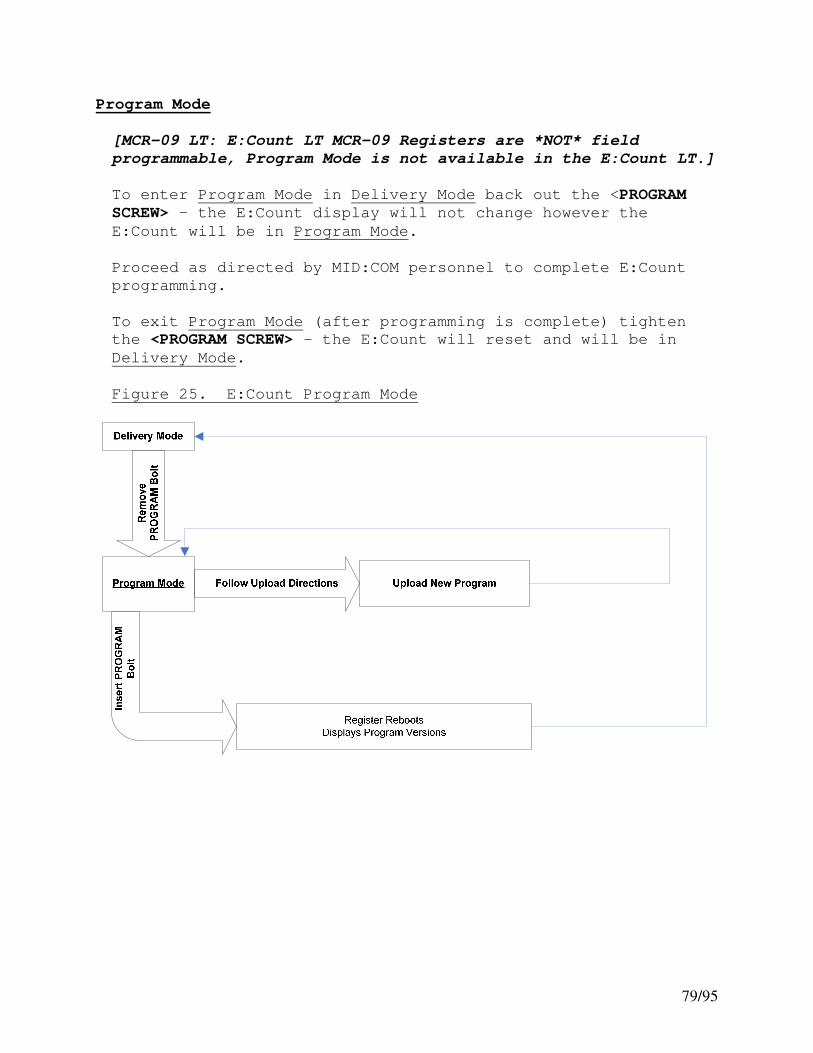
79/95
Program Mode
[MCR-09 LT: E:Count LT MCR-09 Registers are *NOT* field
programmable, Program Mode is not available in the E:Count LT.]
To enter Program Mode in Delivery Mode back out the <PROGRAM
SCREW> – the E:Count display will not change however the
E:Count will be in Program Mode.
Proceed as directed by MID:COM personnel to complete E:Count
programming.
To exit Program Mode (after programming is complete) tighten
the <PROGRAM SCREW> - the E:Count will reset and will be in
Delivery Mode.
Figure 25. E:Count Program Mode

80/95
Power-Up
On Power-up the E:Count will:
1. Reset all display elements 2. Perform a set of diagnostic tests 3. Display the Metrological Software Version: M ## 4. Display the User Software Version: U ## 5. Enter Delivery Mode.

81/95
Section 7 – SAMPLE TICKETS
Figure 26. E:Count Delivery Tickets
�-- This delivery ticket shows all
options enabled.
The delivery ticket below shows
all options disabled.
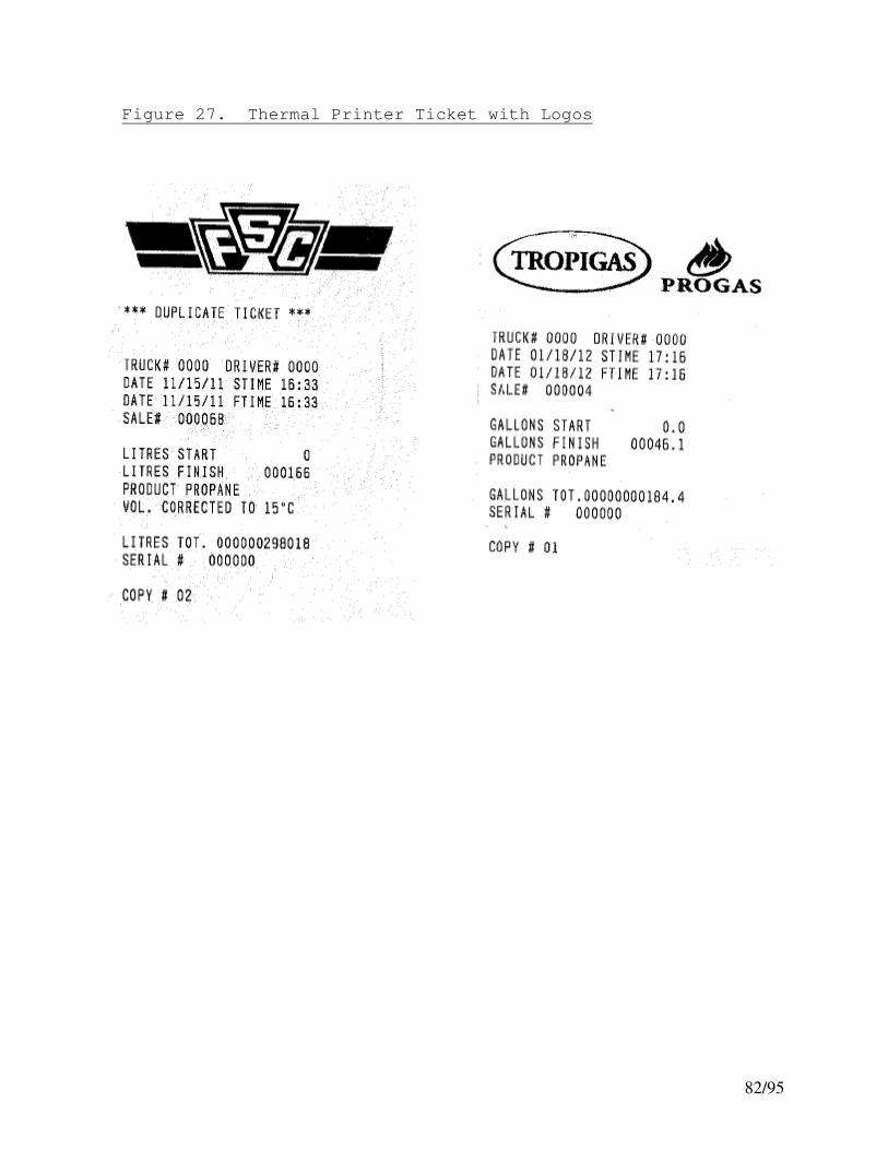
82/95
Figure 27. Thermal Printer Ticket with Logos

83/95
Figure 28. E:Count Calibration and Shift Tickets

84/95
Section 8 – APPENDICES
Appendix A – E:Count MCR-05 to 8000 Interface
[MCR-09 LT: The E:Count LT MCR-09 does *NOT* interface with the
MID:COM 8000 Computer.]
Theory of Operation
The MID:COM 8000 is the ultimate, rugged, easy to use cab
mounted computer, printer, and data transfer system. Using
the SD Data Card the driver has access to 50,000 complete
customer records. An easy-to-follow menu guides the driver
through the delivery process. The most popular software
providers offer a MID:COM SD Card interface that provides
automatic posting from the SD Card to your accounts receivable
accounting package.
The MID:COM 8000 Cab-Mounted Computer has a seamless interface
with the MID:COM E:Count Electronic Register. The combination
of these systems allows fuel distributors to utilize the most
cost-effective, flexible, efficient, secure, and reliable
vehicle-based electronic registration system on the market
today.
Return on Investment
Electronic Temperature Compensation:
• Reduces shrinkage by 1%
• Increases driver efficiency by 10% to 15%
• Reduces meter maintenance by 50%
• Eliminates handwritten tickets and ticket notation
errors
• Reduces ticket posting time and eliminates posting
errors
• Eliminates postage costs
Valve Options
When the MID:COM E:Count Electronic Register is connected to a
MID:COM 8000 Electronic Computer either the E:Count or the
8000 can control the security valves.
The Calibration must be performed on the MID:COM E:Count
regardless of the Valve Control Setting.

85/95
Appendix A – E:Count MCR-05 to 8000 Interface (continued)
There is a separate document that has detailed instructions for
Calibrating the E:Count with a MID:COM 8000 Electronic
Register.
Contact MID:COM or visit the MID:COM website at
www.MidComCorp.com for more information.
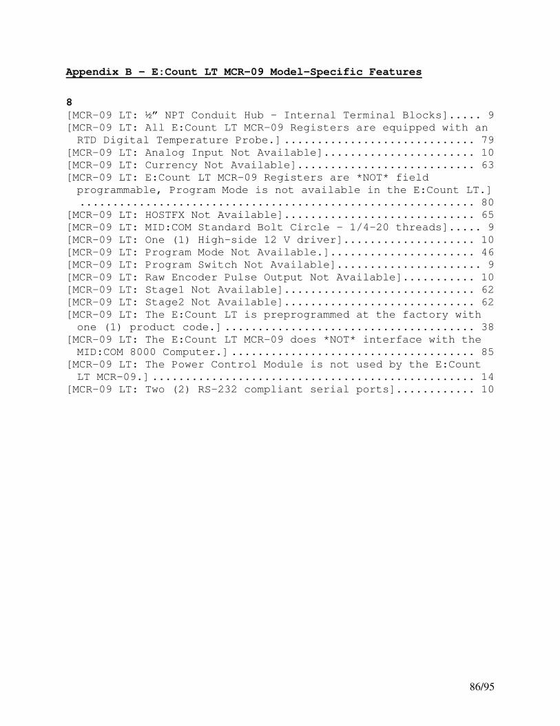
86/95
Appendix B – E:Count LT MCR-09 Model-Specific Features
8
[MCR-09 LT: ½” NPT Conduit Hub – Internal Terminal Blocks]..... 9
[MCR-09 LT: All E:Count LT MCR-09 Registers are equipped with an
RTD Digital Temperature Probe.] ............................. 79
[MCR-09 LT: Analog Input Not Available]....................... 10
[MCR-09 LT: Currency Not Available]........................... 63
[MCR-09 LT: E:Count LT MCR-09 Registers are *NOT* field
programmable, Program Mode is not available in the E:Count LT.]
............................................................ 80
[MCR-09 LT: HOSTFX Not Available]............................. 65
[MCR-09 LT: MID:COM Standard Bolt Circle - 1/4-20 threads]..... 9
[MCR-09 LT: One (1) High-side 12 V driver].................... 10
[MCR-09 LT: Program Mode Not Available.]...................... 46
[MCR-09 LT: Program Switch Not Available]...................... 9
[MCR-09 LT: Raw Encoder Pulse Output Not Available]........... 10
[MCR-09 LT: Stage1 Not Available]............................. 62
[MCR-09 LT: Stage2 Not Available]............................. 62
[MCR-09 LT: The E:Count LT is preprogrammed at the factory with
one (1) product code.] ...................................... 38
[MCR-09 LT: The E:Count LT MCR-09 does *NOT* interface with the
MID:COM 8000 Computer.] ..................................... 85
[MCR-09 LT: The Power Control Module is not used by the E:Count
LT MCR-09.] ................................................. 14
[MCR-09 LT: Two (2) RS-232 compliant serial ports]............ 10

87/95
Appendix C – E:Count LT MCR-09 Installation Reference
Mounting
The E:Count LT uses a four bolt (1/4-20) mounting pattern on
the foot of the unit. If the unit is to be mounted directly to
the flowmeter and uses the internal pulser the appropriate
mounting flange adapter and drive shaft must be ordered for the
particular model and size of meter. The adapter kits are
provided with cross drilled seal bolts so that the unit can be
Weight & Measures sealed after mounting.
If the unit is to be remotely mounted from the meter and an
external pulser used, no additional hardware is required
besides the 4 bolts.
Wiring
All wiring must be accordance with the National Electrical Code
NFPA 70. In particular, if the unit is to be used in a Class
1, Division 2 hazardous location the installation and wiring
must be in accordance with Article 500 of this publication.
Wire size: (refer to Field Wiring Connector Designations)
Power, Ground, Solenoid connections (J1-1,2,3,4) 18-16 AWG
All other connections 22-16 AWG
Terminal Blocks
The unit uses spring loaded terminal blocks that offer a good
connection with vibration and temperature cycling. Prepare the
wire by stripping off about 0.3 inches of insulation. Twist
the strands tightly together. Raise the terminal lever, insert
the wire and press the lever back down. Check for loose
strands and pull on the wire to make ensure a good connection.

88/95
E:Count LT MCR-09 Installation (continued)
Field Wiring Connector Designations
Power:
J1-1 Power in 12 VDC nom. 250 mA Max no valve
2.0 A Max with valve
J1-2 Power ground in
J1-3 Solenoid valve power
J1-4 Solenoid valve ground
J1-5 Auxiliary input 0-20 VDC
J1-6 Auxiliary input Ground
Safety ground - Green screw adjacent to hub
RS-232 communication
J2-1 TX Printer
J2-2 RX Printer
J2-3 Signal ground Printer
J2-4 TX Host
J2-5 RX host
J2-6 Signal ground Host
External Encoder (pulser)
J3-1 Channel B
J3-2 +5 VDC Power
J3-3 Channel A
J3-4 Signal ground
RTD Probe
J2 - Compensator board

89/95
INDEX
“Duty to Warn” message .............. 67
12-volt ....................................................... 20
12-volt power ................................... 15
1st Stage Shut Down .................................. 23
2nd
Stage Shut Down ................................. 23
6501 Print Format .......................... 65
6501PF .................................................... 65
ADD ........................................................... 52
adjustment on all prices ......... 52
air release solenoid................... 39
Air Sensor........................................... 77
air solenoid ...................................... 39
AIRSEN ........................................ 39, 45, 77
Analog Input ...................................... 10
Analog Temperature Probe ......... 78
Asco ......................................................... 26
ATOCAL .............................................. 69, 71
AUTHRX .................................................... 39
Auto-Calibration ...................... 69, 71
Auto-Calibration Delivery....... 69
Batch Mode Preset .......................... 50
Begin ......................................................... 23
Black Mark Sensor .......................... 67
BRKVLV .................................................... 78
Broken Valve Detection .............. 48
CALFAC .................................................... 69
Calibration ........................................ 10
Factor .................. 10, 35, 36, 54, 68, 71
Factor Range .................................. 10
Menu ........... 11, 71, 72, 74, 75, 76, 77, 78
Mode ................................... 46, 68, 70, 78
Report .......................................... 56, 68
Screw....................................... 11, 46, 68
Calibration Delivery............. 69, 71
Calibration Factor ................. 69, 71
Calibration Menu ...................... 69, 70
Calibration Menu Categories .. 70
Celsius .................................................. 56
CHANNL .................................................... 72
Communications ................................. 10
Compensation
Accuracy ........................................... 10
Table................................................... 72
Compensation Table Number....... 69
Compensation Table Reference 40
Compensation Table Value ... 36, 75
Copies .................................................... 64
Currency ............................................... 57
Currency Mode ........... 54, 57, 58, 59, 60
Currency Setting ............................ 63
Decimal Setting............................... 77
Delivery
Menu ....................... 11, 46, 53, 54, 55, 56
Mode .... 11, 47, 53, 54, 55, 56, 57, 60, 61,
66, 71, 80, 81
delivery temperature................... 76
Delivery Ticket................... 11, 47, 68
differential valve ....................... 27
diode .......................................................... 20
diodes ........................................................ 23
Discount Days ................................... 60
Discount Rate ................................... 59
Discount Type ................................... 59
DMICRO .................................................... 43
Driver Code ........................................ 55
E:Count LT........................................... 88
E:Count Power Cable Connector
............................................................... 16
Edit Product Price ....................... 47
Editing Product Price ................ 52
Electrical Requirements ............. 9
Electronic Air Eliminator. 39, 77
Electronic Air Sensor ................ 39
Emergency Stop ................................. 47
Enclosure ............................................... 9
Enclosure Rating .............................. 9
Encoder Channels ............................ 72
Environmental Testing .................. 9
ERROR PRESS PRINT .......................... 41
Faceplate ............................................. 75
Fahrenheit........................................... 56
Ferrite Cylinder Clamp ............................. 21 Firmware Version .... See Software
Version

90/95
FLODIR .................................................... 72
Flow Direction ................................. 72
Flow Rate ............................................. 40
FR xxx ......................... See Flow Rate
frame of the truck ....................... 15
Fuel Delivery Ticket....... 82, 83, 84
fuse block........................................... 15
fuse panel........................................... 15
Gallons .................................................. 76
geysers .................................................. 39
Gross Meter Calibration
Factor ................................................ 69
Ground from Truck Frame ........... 16
High Flow Rate ................................. 77
Hose Pack ............................................. 54
Hose Pack Setting .......................... 64
Hose Packing ................................ 45, 48
hose reel .................................................... 20
Hose Selection ................................. 39
HOSSEL .................................................... 39
Host Authorization ....................... 39
Host Mode Delivery is
interrupted by a Power
Failure .............................................. 42
HostFix .................................................. 44
HostFix Setting............................... 65
HOSTFX .................................................... 44
HOSTFX ALL........................................... 44
HOSTFX MATRIX ................................... 44
HOSTFX OFF........................................... 44
Humidity ................................................. 9
ignition ................................... 15, 16, 41
Ignition Signal............................... 16
Inputs/Outputs ................................. 10
Interconnect ........................................ 9
interrupted delivery................... 41
KILOS....................................................... 76
Litres .................................................... 76
logo file ............................................. 67
Logo Printing ................................... 67
Logo Printing in the Fujitsu
FP-460 ................................................ 67
logo to be converted................... 67
logo will be printed................... 67
MASS ......................................................... 76
MASS mode compensator is
turned off....................................... 76
Mass or Volume ........................... 40, 76
Matrix .................................................... 44
MCR-09 9, 10, 11, 14, 35, 46, 47, 49, 62, 63,
65, 79, 80, 85, 88
Meter Ratio .................................. 74, 75
Metrological Sealing..................... 9
MidCom 8000 ........................................ 85
Money....................................................... 54
MONEY....................................................... 52
Money Mode......................... 57, 58, 59, 60
Mounting ................................................. 9
MRATIO .................................................... 69
Multiple Presets ............................ 51
MULTIPLE TANK DELIVERY AT ONE
SITE ONLY ......................................... 55
negative terminal of the
battery .............................................. 15
NOGOOD .................................................... 39
Open Stage 2 ...................................... 54
Open Valve to Pack the Hose .. 54
Operating Current ............................ 9
Operating Environment .................. 9
Operating Voltage ............................ 9
optical sensor ................................. 39
outlet solenoid valves .............. 39
outlet valves ................................... 39
Pack the Hose ............................. 48, 54
PCM ........................................................... 41
PLSREV .................................................... 72
positive terminal of the
battery .............................................. 15
POUNDS .................................................... 76
power....................................................... 16
power cable assembly................... 15
Power Failure ............................. 32, 41
POWER FAILURE ................................... 41
Power Failure During a Host
Mode Delivery ............................... 42
Power Latching ................................. 41
power monitoring ............................ 41
Powered Control Outputs ........... 10

91/95
Power-Up ............................................... 81
PRCADJ .................................................... 52
Prescale Factor Range ................ 10
preset ......................................................... 23
Preset Before the Delivery .... 50
Preset Key Enabled/Disabled .. 66
Preset Key Setting ....................... 66
Preset Money Amount ..................... 50
Preset on Dollars .................... 47, 50
Preset Operation ............................ 49
Preset Required............................... 63
Preset Required Setting ........... 63
Preset Screen ................................... 51
preset valve ...................................... 25
Preset Volume ................. 11, 46, 47, 51
Price................................................. 57, 58
price adjustment ...................... 52, 60
Price Adjustment ............................ 57
Print + Preset Key Setting .... 66
Print Gross ........................................ 76
Print Key Enabled/Disabled .... 66
Print Key Setting .......................... 66
Printer
Thermal .............................................. 64
Printer .................................................. 47
Copies ................................................ 64
NO PRINTER....................................... 63
Thermal Printer Ticket
Copies ............................................ 64
Printer setting “FP-460” ......... 67
Printer Type ...................................... 63
Printing Options ............................ 67
PROBE....................................................... 78
Product Code .................... 11, 54, 68, 71
Program Mode ................................ 46, 80
Program Screw ............................. 46, 80
Prover .................................................... 69
Prover Delivered Volume ........... 69
Prover Volume ............................. 69, 71
PS RQD .................................................... 63
Pulse Input ........................................ 10
Pulse Output ...................................... 10
Pulses per Revolution ................ 72
QOB ........................................................... 54
Quantity on Board .......................... 54
Raw Pulses........................................... 69
reel switch ................................................. 20
Registration Capacity ................ 10
RTD Digital Temperature Probe
............................................................... 78
Sale Number ........................................ 63
SD Card .................................................. 85
SD Data Card ...................................... 85
Security Code ................. 53, 56, 61, 62
Security Valve ..................... 46, 47, 68
Serial Number ............................. 75, 76
Setup Mode 53, 56, 58, 61, 62, 63, 64, 65,
66
Shield .................................................... 16
Shift Report ...................................... 55
Shock......................................................... 9
Skinner .................................................. 26
Slow Flow Valve............................... 54
SLS ........................................................... 25
Software Version
Metrological .................................. 81
User ..................................................... 81
solenoid ............................. 15, 20, 23, 26
solenoids ............................................. 20, 23
source of pressure ....................... 27
spike suppressor ........................................ 20
Stage 1 Shutoff............................... 62
Stage 2 Dwell ................. 54, 62, 68, 71
Start/Stop Reset ............................ 64
SUB ........................................................... 52
Subtotal Tax ...................................... 59
suppressor ................................................. 20
System Date ........................................ 62
System Time ........................................ 62
Tax 1 Rate........................................... 58
Tax 1 Subject to Tax 2 ........ 57, 59
Tax 1 Type........................................... 58
Tax 2 Rate........................................... 58
Tax 2 Type........................................... 59
Temperature
Celsius .............................................. 72
Current ........................................ 56, 72

92/95
Fahrenheit....................................... 72
Temperature Compensation .. 11, 55,
75
Temperature Probe .......................... 78
Temperature Range ............................ 9
Timer....................................................... 75
Timer Override ........................... 55, 75
Totalizer ....................................... 10, 55
Gross................................................... 55
Net ....................................................... 55
truck battery ................................... 15
truck frame ........................................ 15
Truck Number ...................................... 63
U TYPE .............................................. 40, 76
Unit Type ....................................... 40, 76
Unit Type MASS ................................. 76
Unit Type VOLUME ............................ 76
Units....................................................... 40
valve cable ........................................ 25
valves fail ........................................ 48
vapor line........................................... 27
Vibration ............................................... 9
Volume .................................................... 76
Gross....................................... 56, 68, 71
Net ........................................... 56, 68, 71

93/95
VERSION HISTORY
Version Date Author Description
1.01 09-27-05 BJS Document created
1.02 02-28-06 BJS Updated menus
1.03 03-06-06 BJS Updated menus
1.04 03-15-06 BJS Updated descriptions, added images
1.05 03-16-06 BJS Added E:Count to 8000 Interface
1.06 03-20-06 BJS Updated Images
1.07 07-17-06 BJS Added E109D menu changes
1.08 08-02-06 BJS Added E110E changes and QCRs
1.09 08-15-06 BJS Added Currency changes
1.10 08-21-06 BJS Added Timer and Print Gross Changes
1.11 08-22-06 BJS Updated images
1.12 12-14-06 BJS Updated menus
1.13 12-14-06 BJS Added Calibration Instructions
1.14 12-15-06 BJS Updated Copyright
1.15 12-15-06 BJS Corrections
1.16 12-15-06 BJS Corrections
1.17 12-17-06 BJS Updated Discount Type Notes
1.18 12-18-06 BJS Updated Sample Tickets
1.19 03-21-07 BJS Updated Preset Info
1.20 03-22-07 BJS Updates and Corrections
1.21 03-23-07 BJS Update JET-B and Ethanol
1.22 05-16-07 BJS Update AIRSEN and TIMOVR
1.23 06-12-07 BJS Update PROBE
1.24 06-20-07 BJS Add Editing Price During Delivery
1.25 07-18-07 BJS Add HOSEPK, QOB, and Valve notes
1.26 07-24-07 BJS Add Power Failure notes
1.27 07-25-07 BJS Updated Printer Types
1.28 08-02-07 BJS Updated Command Reference
1.29 08-06-07 BJS Added Auto-Calibration
1.30 08-09-07 BJS Updated Multiple Presets
1.31 08-09-07 BJS Updated Power Cable Connection
1.32 08-24-07 BJS Update Command Reference
1.33 10-23-07 BJS Update PGROSS for temperature print
1.34 10-24-07 BJS Update Command Reference
1.35 10-25-07 BJS Update Command Reference
1.36 10-26-07 BJS Update images
1.37 10-30-07 BJS Update Indexes, TOC

94/95
Version Date Author Description
1.38 12-10-07 BJS Update Indexes, TOC, and QCR
1.39 12-11-07 BJS Update QCR
1.40 03-14-08 BJS Update QCR
1.41 04-03-08 BJS Update Flow Rate, Mass, Preset $
1.42 04-08-08 BJS Update Hose Pack, QCR, Preset $
1.43 04-14-08 BJS Tax1 Subject to Tax 2, QCR
1.44 05-07-08 BJS TIMOVR Update, QCR
1.45 07-16-08 BJS Add Serial Cables, PRCADJ, SS RST
1.46 09-23-08 BJS Update QCR
1.47 10-28-08 BJS Update QCR
1.48 11-19-08 BJS QCR, Cables, E164E and DM11
1.49 12-29-08 BJS Update QCR E165E
1.50 01-16-09 BJS Preset, QCR
1.51 03-05-09 BJS Update QCR
1.52 03-18-09 BJS Update QCR
1.53 07-22-09 BJS Update 8000 Printer port type
1.54 08-03-09 BJS Citizen CTS-310 Thermal Printer
1.54 10-09-09 BJS 6501 Print Format, QCR
1.55 11-19-09 BJS Valve Wiring, MRATIOS
1.55 01-06-10 BJS Sample Tickets, QCR
1.56 01-25-10 BJS E:Count LT MCR-09 Model Notes
1.57 05-11-10 BJS Cal Mode Notes
1.58 05-11-10 BJS Hardware Notes from 8000 Guide
1.59 06-02-10 BJS Update Delivery Mode Flowchart E170E-1.00 10-26-10 BJS Update QCR, Printers E170E-1.01 11-23-10 BJS Add Power Latching E172E-1.00 04-08-11 BJS Update for E172E Release E173F-1.00 06-21-11 BJS Update for Black Mark, Logo, 173F E173F-1.01 06-28-11 BJS Update Logs and Black Mark Sensors E174F-1.00 12-21-11 BJS QCR, 174F E174F-1.01 02-16-12 BJS Update Sample Tickets E175F-1.00 03-27-12 BJS Setup Menu Cmds, Tables, QCR, 175F E176F-1.00 05-22-12 BJS QCR, 176F E176F-1.01 06-07-12 BJS SS_RST = NSSOHM E177F-1.00 10-11-12 BJS QCR, Batch Mode, E177F E177f-1.01 10-24-12 BJS QCR, PGROSS E177f-1.02 10-31-12 BJS QCR, Demo Mode E178F-1.00 05-20-13 BJS Printers, QCR E179E0-v100 09-30-13 BJS 179 Release E179E0-v101 01-16-14 BJS QCR, Remove Batch in E179_4, AIRSEN

95/95
Version Date Author Description E179E0-v102 02-10-14 BJS Jumper on AIRSEN for LT
ECount Users Guide E180E0 v1.00.docx