Embed Size (px)
Citation preview

Leon Bruckman, IP Light
Remus Tan, Ciena
eCPRI introduction
Draft to be submitted
September 26, 2017
Burnaby, Canada
– The eCommon Public Radio Interface (eCPRI) is an industry cooperation aimed at defining a publicly available specification for the key internal interface of radio base stations connecting the eCPRI Radio Equipment Control (eREC) and the eCPRIRadio Equipment (eRE) via a so-called fronthaul transport network.
– The parties cooperating to define the specification are Ericsson AB, Huawei Technologies Co. Ltd, NEC Corporation and Nokia Solutions and Networks GmbH & Co. KG.
– Motivation for eCPRI:• The eCPRI specification enables flexible and efficient product
differentiation for radio base stations and independent technology evolution for eCPRI Radio Equipment (eRE) and eCPRI Radio Equipment Control (eREC).
2
Introduction and motivation
– The necessary items for transport, connectivity and control are included in the specification. This includes User Plane data, Control and Management Plane transport mechanisms, and means for synchronization.
– The new Specification (eCPRI) will support the 5G Front-haul and will include increased efficiency in order to meet the needs foreseen for 5G Mobile Networks.
• The eCPRI specification will be based on new functional partitioning of the cellular base station functions, positioning the split point inside the Physical Layer (i.e. Layer 1).
– A focus has been put on the definition of a specific eCPRI protocol layer that can be used on top of existing mainstream L2 or L3 transport protocols like Ethernet or IP.
• This eCPRI protocol layer provides various - mainly user plane data specific -services to the upper layers of the protocol stack.
– With a clear focus on HW related protocol layers, the scope of the eCPRIspecification is restricted to the interface towards to enable efficient and flexible radio data transmission via a packet based fronthaul transport network like IP or Ethernet.
– Redundancy mechanisms are not described in the eCPRI specification, however all the necessary features to support redundancy, especially in system architectures providing redundant physical interconnections (e.g. rings) are defined.
3
Scope
4
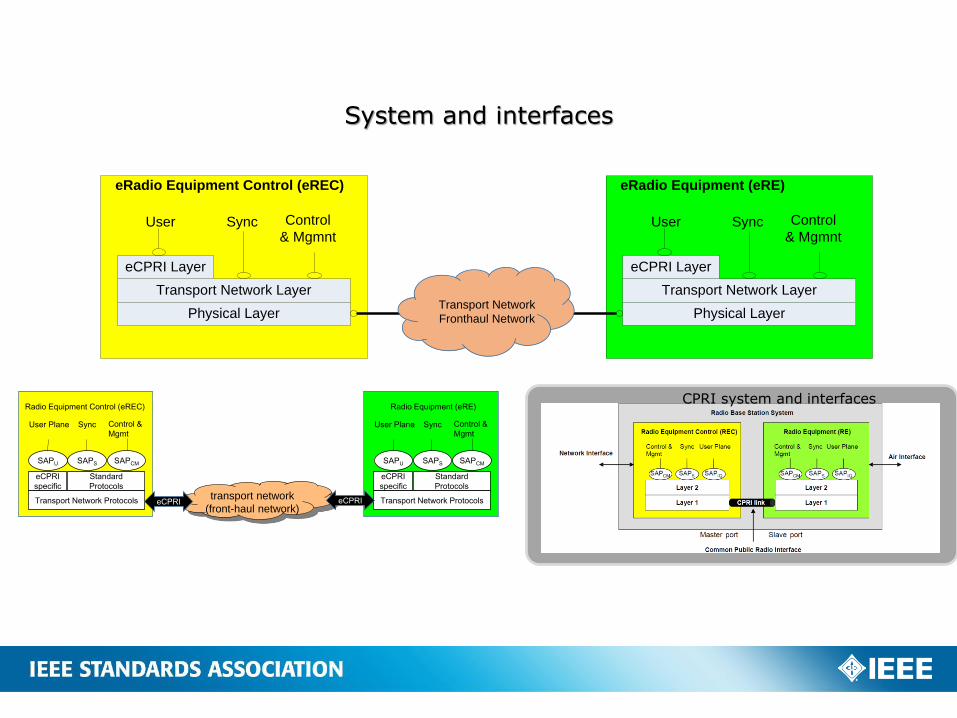
System and interfaces
Transport Network Layer
Physical Layer
eCPRI Layer
User Sync Control
& Mgmnt
eRadio Equipment Control (eREC)
Transport Network Layer
Physical Layer
eCPRI Layer
User Sync Control
& Mgmnt
eRadio Equipment (eRE)
Transport Network
Fronthaul Network
CPRI system and interfaces
SAPCMSAPSSAPU
User Plane Sync Control &
Mgmt
eCPRI
specific
Standard
Protocols
Transport Network Protocols
Radio Equipment Control (eREC)
SAPCMSAPSSAPU
User Plane Sync Control &
Mgmt
eCPRI
specific
Standard
Protocols
Transport Network Protocols
Radio Equipment (eRE)
transport network
(front-haul network)eCPRI eCPRI
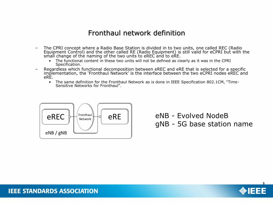
– The CPRI concept where a Radio Base Station is divided in to two units, one called REC (Radio Equipment Control) and the other called RE (Radio Equipment) is still valid for eCPRI but with the small change of the naming of the two units to eREC and to eRE.
• The functional content in these two units will not be defined as clearly as it was in the CPRI Specification.
– Regardless which functional decomposition between eREC and eRE that is selected for a specific implementation, the ‘Fronthaul Network’ is the interface between the two eCPRI nodes eREC and eRE.
• The same definition for the Fronthaul Network as is done in IEEE Specification 802.1CM, “Time-Sensitive Networks for Fronthaul”.
5
Fronthaul network definition
eREC FronthaulNetwork eRE
eNB / gNB
eNB - Evolved NodeBgNB - 5G base station name
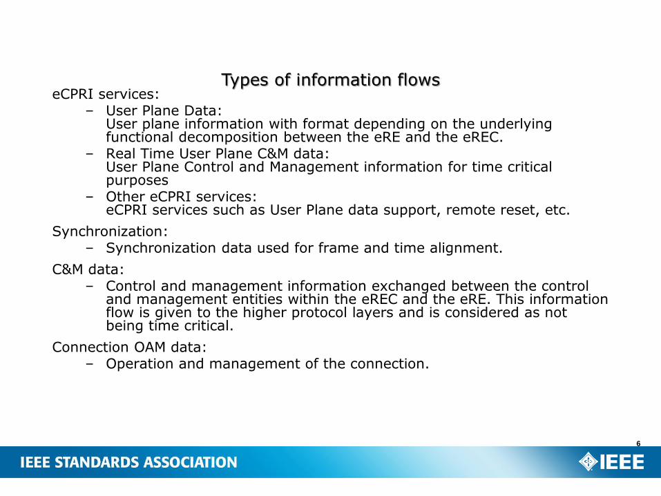
eCPRI services:– User Plane Data:
User plane information with format depending on the underlying functional decomposition between the eRE and the eREC.
– Real Time User Plane C&M data:User Plane Control and Management information for time critical purposes
– Other eCPRI services:eCPRI services such as User Plane data support, remote reset, etc.
Synchronization:– Synchronization data used for frame and time alignment.
C&M data:– Control and management information exchanged between the control
and management entities within the eREC and the eRE. This information flow is given to the higher protocol layers and is considered as not being time critical.
Connection OAM data:– Operation and management of the connection.
6
Types of information flows
7
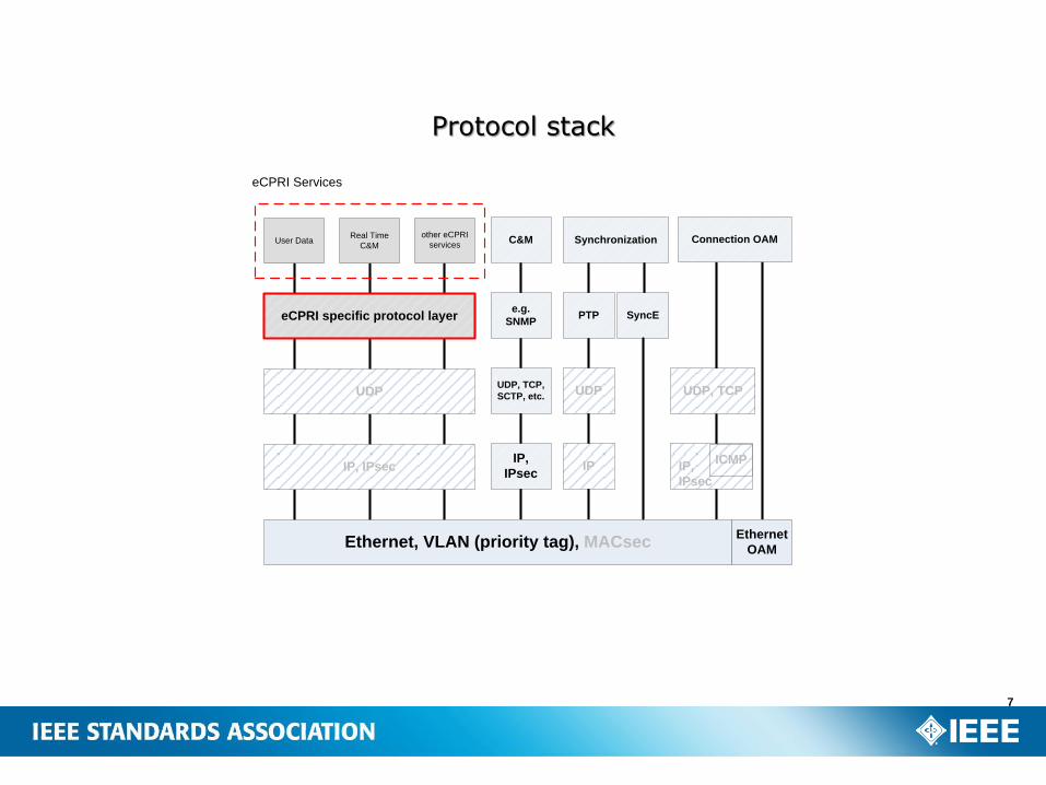
Protocol stack
Ethernet, VLAN (priority tag), MACsec
IP, IPsec
UDP
eCPRI specific protocol layer
User DataReal Time
C&M
eCPRI Services
IP,
IPsec
UDP, TCP,
SCTP, etc.
e.g.
SNMPPTP
C&M Synchronizationother eCPRI
services
SyncE
IP
UDP
Connection OAM
Ethernet
OAM
IP,
IPsec
UDP, TCP
ICMP
8
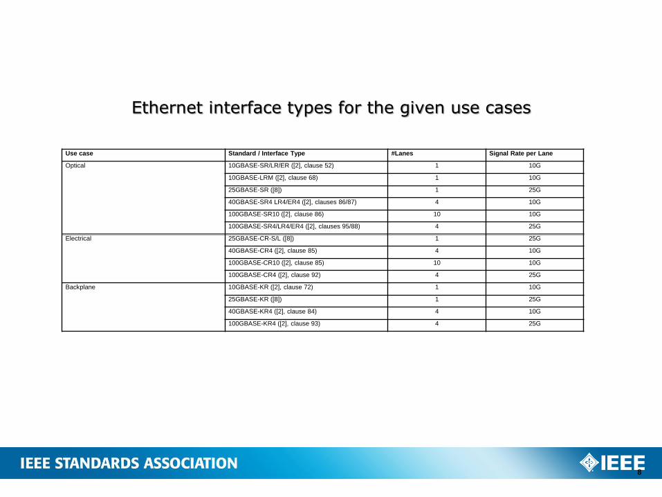
Ethernet interface types for the given use cases
Use case Standard / Interface Type #Lanes Signal Rate per Lane
Optical 10GBASE-SR/LR/ER ([2], clause 52) 1 10G
10GBASE-LRM ([2], clause 68) 1 10G
25GBASE-SR ([8]) 1 25G
40GBASE-SR4 LR4/ER4 ([2], clauses 86/87) 4 10G
100GBASE-SR10 ([2], clause 86) 10 10G
100GBASE-SR4/LR4/ER4 ([2], clauses 95/88) 4 25G
Electrical 25GBASE-CR-S/L ([8]) 1 25G
40GBASE-CR4 ([2], clause 85) 4 10G
100GBASE-CR10 ([2], clause 85) 10 10G
100GBASE-CR4 ([2], clause 92) 4 25G
Backplane 10GBASE-KR ([2], clause 72) 1 10G
25GBASE-KR ([8]) 1 25G
40GBASE-KR4 ([2], clause 84) 4 10G
100GBASE-KR4 ([2], clause 93) 4 25G
eCPRI messages shall be transmitted in standard Ethernet frames. – The Ethernet network shall follow the definitions of IEEE Specification 802.1CM, “Time-Sensitive
Networks for Fronthaul”.
– The type field of the Ethernet frame shall contain the eCPRI Ethertype.
– The data field of the Ethernet frame shall contain the eCPRI header at its beginning, followed immediately by the eCPRI data.
– The eCPRI message shall be embedded in the Ethernet frame as a series of octets.
As the minimum size of the data field of an Ethernet frame is 46 octets, if necessary, the eCPRI data field should be padded with octets of zero to fill up this minimum size.
– This padding is not part of the eCPRI message and so is not to be included in the message size field of the eCPRI header.
An eCPRI node involved in an eCPRI over Ethernet message exchange shall have at least one unique Ethernet MAC address assigned to it.
– The mapping of eCPRI services to Ethernet MAC addresses and how this mapping information is exchanged between eCPRI nodes are out of scope of the eCPRI specification.
The Ethernet MAC header shall provide enough information about the source and the destination of the eCPRI message to deliver the message successfully through the Ethernet network, with the required priority.
Further details of the format and definition of the Ethernet frame are out of scope of the eCPRI specification.
9
eCPRI over Ethernet
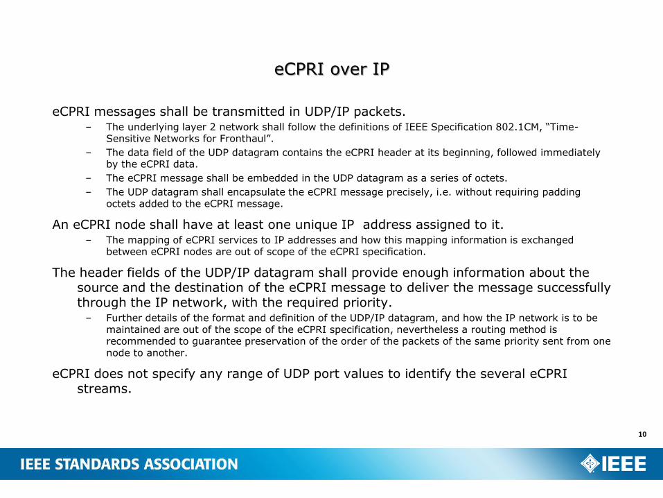
eCPRI messages shall be transmitted in UDP/IP packets. – The underlying layer 2 network shall follow the definitions of IEEE Specification 802.1CM, “Time-
Sensitive Networks for Fronthaul”.
– The data field of the UDP datagram contains the eCPRI header at its beginning, followed immediately by the eCPRI data.
– The eCPRI message shall be embedded in the UDP datagram as a series of octets.
– The UDP datagram shall encapsulate the eCPRI message precisely, i.e. without requiring padding octets added to the eCPRI message.
An eCPRI node shall have at least one unique IP address assigned to it. – The mapping of eCPRI services to IP addresses and how this mapping information is exchanged
between eCPRI nodes are out of scope of the eCPRI specification.
The header fields of the UDP/IP datagram shall provide enough information about the source and the destination of the eCPRI message to deliver the message successfully through the IP network, with the required priority.
– Further details of the format and definition of the UDP/IP datagram, and how the IP network is to be maintained are out of the scope of the eCPRI specification, nevertheless a routing method is recommended to guarantee preservation of the order of the packets of the same priority sent from one node to another.
eCPRI does not specify any range of UDP port values to identify the several eCPRIstreams.
10
eCPRI over IP
11
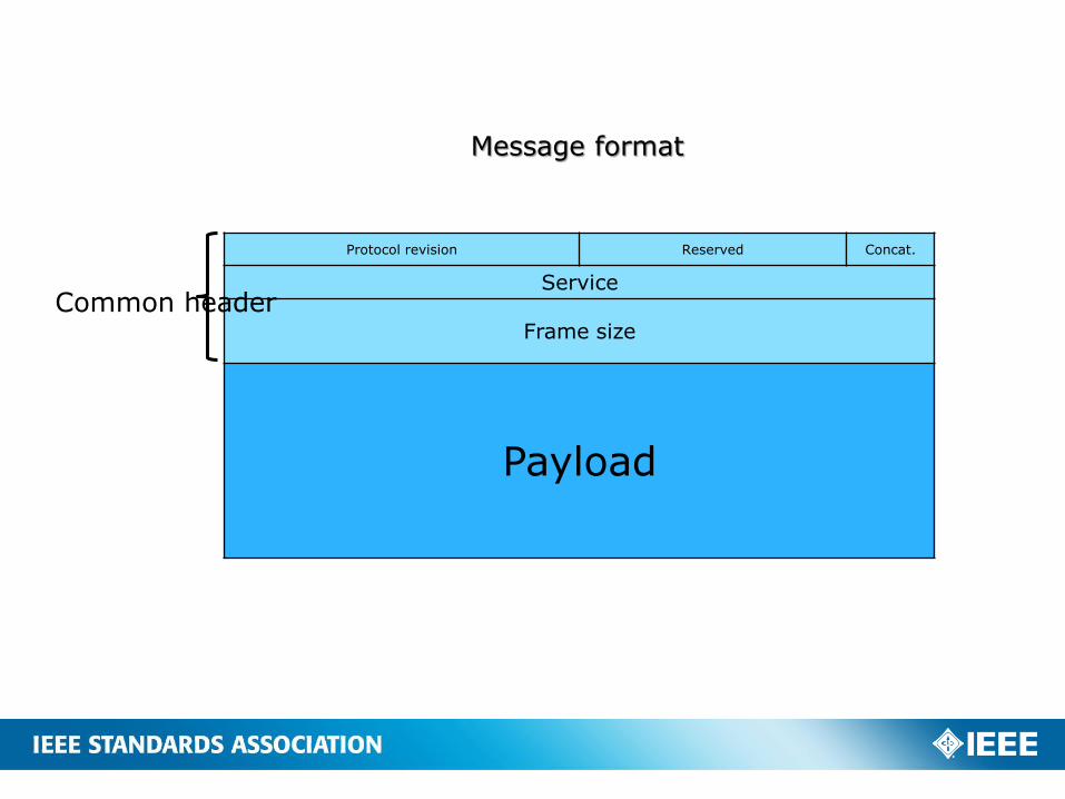
Message format
Concat.ReservedProtocol revision
Service
Frame size
Payload
Common header
12
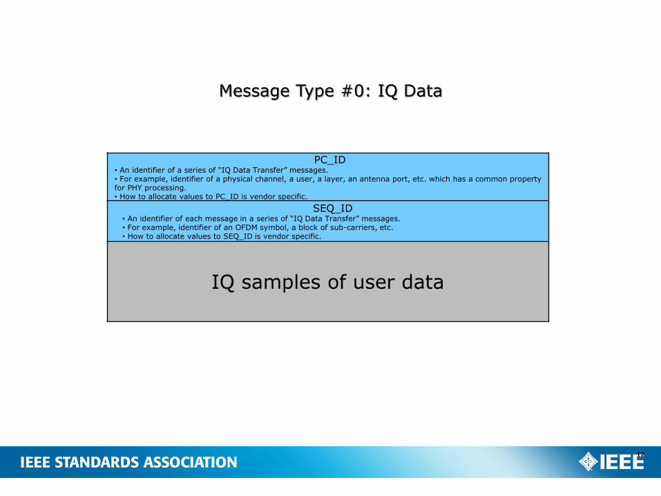
Message Type #0: IQ Data
PC_ID• An identifier of a series of “IQ Data Transfer” messages.• For example, identifier of a physical channel, a user, a layer, an antenna port, etc. which has a common property for PHY processing.• How to allocate values to PC_ID is vendor specific.
SEQ_ID• An identifier of each message in a series of “IQ Data Transfer” messages.• For example, identifier of an OFDM symbol, a block of sub-carriers, etc.• How to allocate values to SEQ_ID is vendor specific.
IQ samples of user data
13
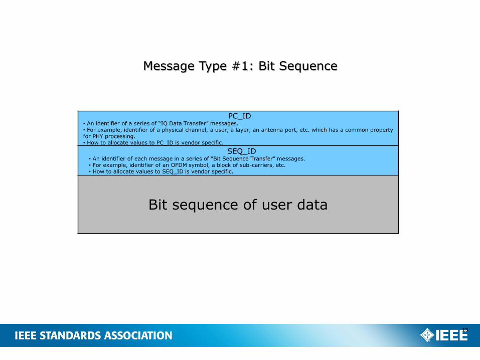
Message Type #1: Bit Sequence
PC_ID• An identifier of a series of “IQ Data Transfer” messages.• For example, identifier of a physical channel, a user, a layer, an antenna port, etc. which has a common property for PHY processing.• How to allocate values to PC_ID is vendor specific.
SEQ_ID• An identifier of each message in a series of “Bit Sequence Transfer” messages.• For example, identifier of an OFDM symbol, a block of sub-carriers, etc.• How to allocate values to SEQ_ID is vendor specific.
Bit sequence of user data
14
Message Type #2: Real-Time Control Data
Real time control message
15
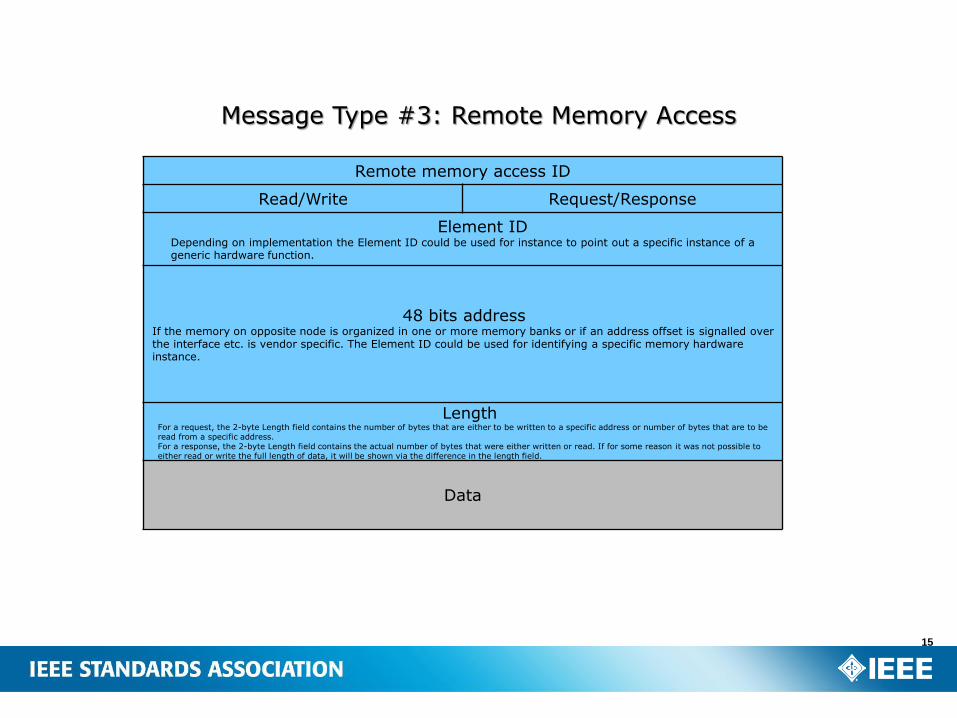
Message Type #3: Remote Memory Access
Remote memory access ID
Request/ResponseRead/Write
Element IDDepending on implementation the Element ID could be used for instance to point out a specific instance of a generic hardware function.
48 bits addressIf the memory on opposite node is organized in one or more memory banks or if an address offset is signalled over the interface etc. is vendor specific. The Element ID could be used for identifying a specific memory hardware instance.
LengthFor a request, the 2-byte Length field contains the number of bytes that are either to be written to a specific address or number of bytes that are to be read from a specific address.For a response, the 2-byte Length field contains the actual number of bytes that were either written or read. If for some reason it was not possible to either read or write the full length of data, it will be shown via the difference in the length field.
Data
16
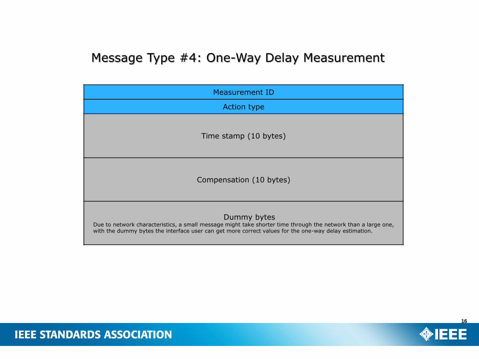
Message Type #4: One-Way Delay Measurement
Measurement ID
Action type
Time stamp (10 bytes)
Compensation (10 bytes)
Dummy bytesDue to network characteristics, a small message might take shorter time through the network than a large one, with the dummy bytes the interface user can get more correct values for the one-way delay estimation.
17
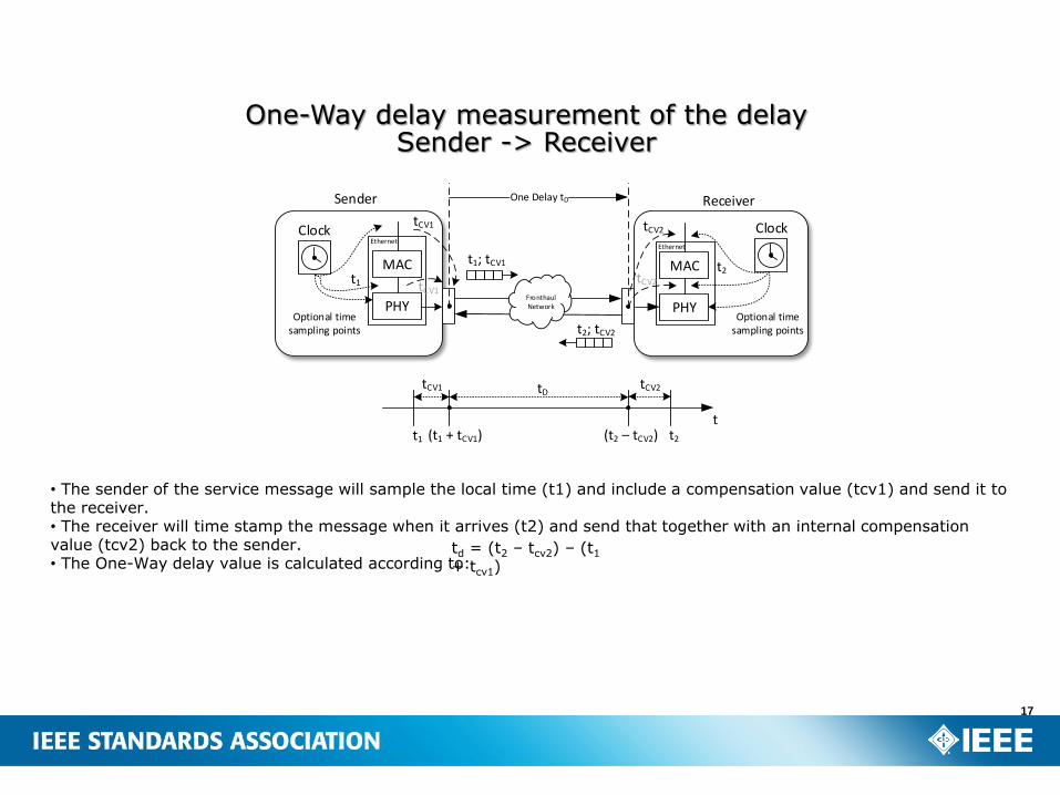
One-Way delay measurement of the delay Sender -> Receiver
MAC
Sender Receiver
t1
t1; tCV1 t2
tCV1
PHY
MAC
PHY
Clock Clock
One Delay tD
tCV2Ethernet
Ethernet
FronthaulNetwork
t1 (t1 + tCV1) t2(t2 – tCV2)
tCV1 tCV2tD
t
t2; tCV2
Optional time sampling points
Optional time sampling points
tCV1tCV2
td = (t2 – tcv2) – (t1
+ tcv1)
• The sender of the service message will sample the local time (t1) and include a compensation value (tcv1) and send it to the receiver. • The receiver will time stamp the message when it arrives (t2) and send that together with an internal compensation value (tcv2) back to the sender.• The One-Way delay value is calculated according to:
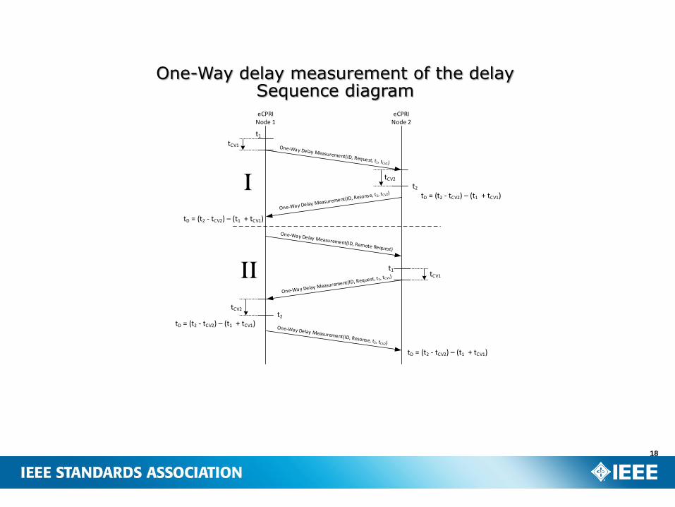
18
One-Way delay measurement of the delay Sequence diagrameCPRI
Node 1eCPRI
Node 2
t1
tCV1
t2
tD = (t2 - tCV2) – (t1 + tCV1)
tCV2
tD = (t2 - tCV2) – (t1 + tCV1)
tCV1
t2
tCV2
t1
tD = (t2 - tCV2) – (t1 + tCV1)
tD = (t2 - tCV2) – (t1 + tCV1)
I
II
19
Message Type #5: Remote Reset
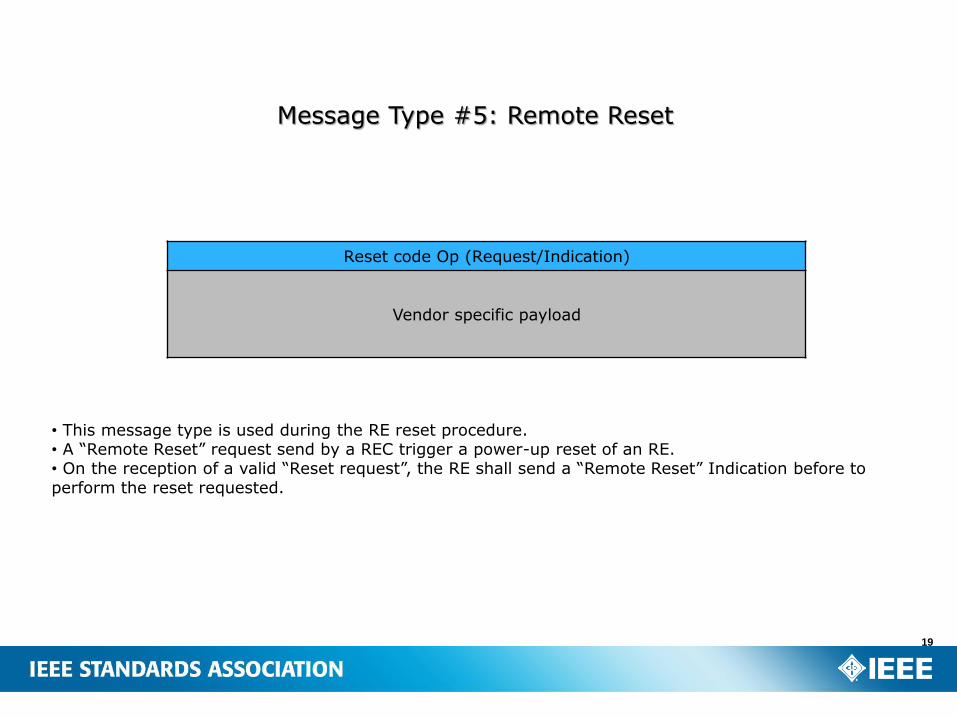
Reset code Op (Request/Indication)
Vendor specific payload
• This message type is used during the RE reset procedure. • A “Remote Reset” request send by a REC trigger a power-up reset of an RE. • On the reception of a valid “Reset request”, the RE shall send a “Remote Reset” Indication before to perform the reset requested.
20
Message Type #6: Event Indication
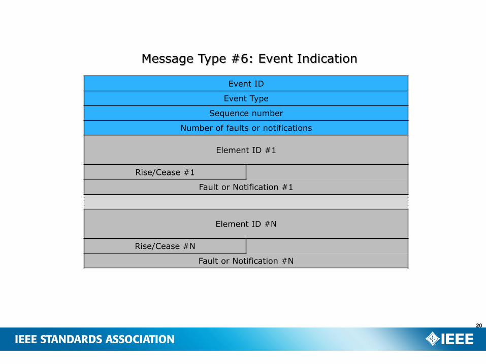
Event ID
Event Type
Sequence number
Number of faults or notifications
Element ID #1
Rise/Cease #1
Fault or Notification #1
Element ID #N
Rise/Cease #N
Fault or Notification #N
Event indication sequence diagram
eCPRINode 1
eCPRINode 2
On
e sy
nch
ron
izat
ion
pro
cedu
re
Event Indication(Event_ID, Event_Type, Seq_Nr,{Faults(s)/Notifications(s)})
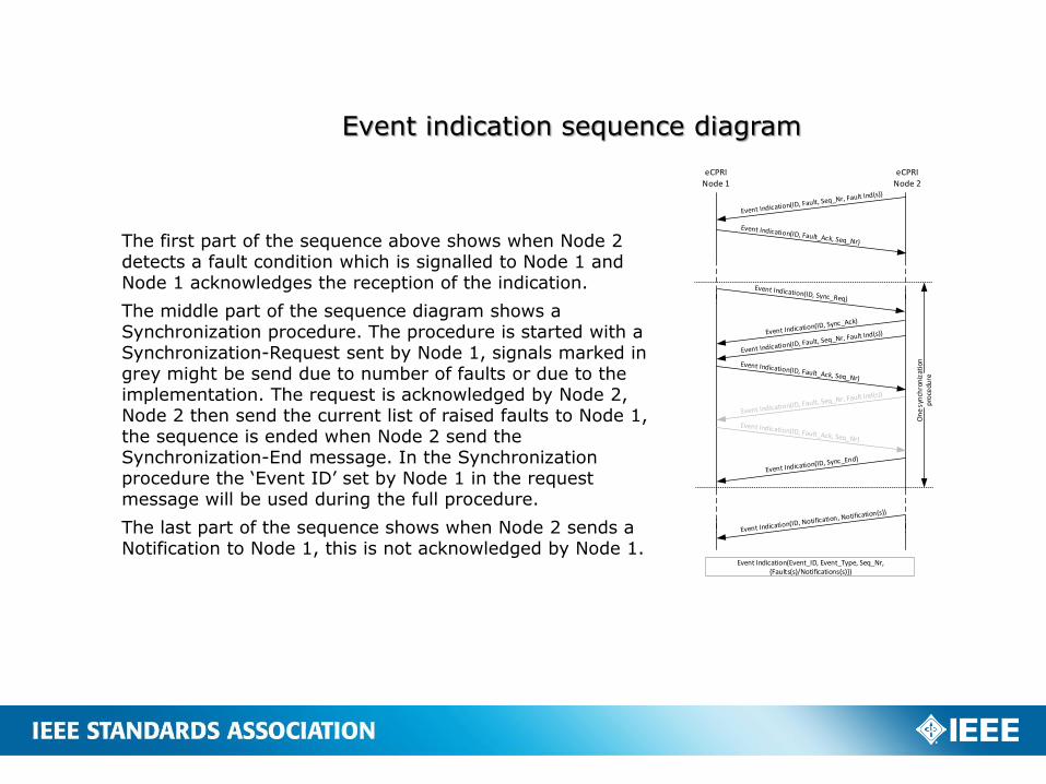
The first part of the sequence above shows when Node 2 detects a fault condition which is signalled to Node 1 and Node 1 acknowledges the reception of the indication.
The middle part of the sequence diagram shows a Synchronization procedure. The procedure is started with a Synchronization-Request sent by Node 1, signals marked in grey might be send due to number of faults or due to the implementation. The request is acknowledged by Node 2, Node 2 then send the current list of raised faults to Node 1, the sequence is ended when Node 2 send the Synchronization-End message. In the Synchronization procedure the ‘Event ID’ set by Node 1 in the request message will be used during the full procedure.
The last part of the sequence shows when Node 2 sends a Notification to Node 1, this is not acknowledged by Node 1.
Control and management information will be exchanged between eCPRI entities (eREC and eRE) on any commonly used transport protocols. I.e. the C&M information will not be transmitted via the eCPRI specific protocol.
– The details of this information flow is out of scope of this eCPRI specification.
– The intention is that this information will use protocols (e.g. TCP) over the IP protocol but any other solution is not precluded.
The C&M information flow will be considered as non-time-critical and utilize a small part of the total bandwidth between eCPRIentities.
– The majority of this information flow will be considered as low priority traffic but a small portion of emergency (high priority) traffic may be needed.
22
C&M plane
23
eCPRI Functional Decomposition
MAC
Coding
RateMatching
Scrambling
Modulation
LayerMapping
PrecodingTX Power
ResourceElementMapping
iFFT
Cyclic PrefixInsertion
RLC
RF
MAC
Rate
Matching
De-
scrambling
De-modulation
iDFT
ResourceElement
Demapping
FFT
Cyclic PrefixRemoval
RLC
RF
De-
coding
PH
Y
ID
IID
E
PortReduction
ChannelEstimation
DiversityCombiner
Equalization
BeamformingPort Expansion
D
IU
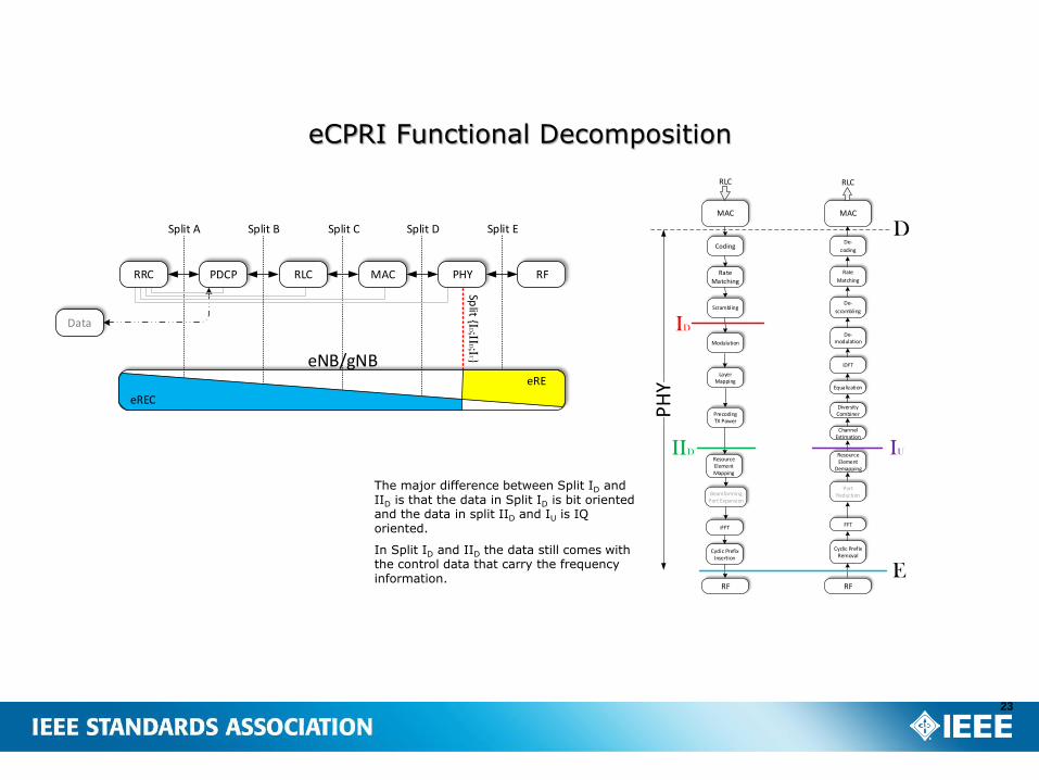
The major difference between Split ID and IID is that the data in Split ID is bit oriented and the data in split IID and IU is IQ oriented.
In Split ID and IID the data still comes with the control data that carry the frequency information.
RF
Data
Split A Split B Split C Split D
Split {I
D;IID;I
U}
RLCPDCPRRC MAC PHY
Split E
eNB/gNB
eREC
eRE
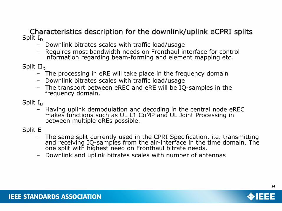
Split ID
– Downlink bitrates scales with traffic load/usage– Requires most bandwidth needs on Fronthaul interface for control
information regarding beam-forming and element mapping etc.
Split IID
– The processing in eRE will take place in the frequency domain– Downlink bitrates scales with traffic load/usage– The transport between eREC and eRE will be IQ-samples in the
frequency domain.
Split IU
– Having uplink demodulation and decoding in the central node eRECmakes functions such as UL L1 CoMP and UL Joint Processing in between multiple eREs possible.
Split E– The same split currently used in the CPRI Specification, i.e. transmitting
and receiving IQ-samples from the air-interface in the time domain. The one split with highest need on Fronthaul bitrate needs.
– Downlink and uplink bitrates scales with number of antennas
24
Characteristics description for the downlink/uplink eCPRI splits
25
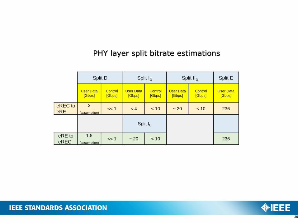
PHY layer split bitrate estimations
Split D Split ID Split IID Split E
User Data
[Gbps]
Control
[Gbps]
User Data
[Gbps]
Control
[Gbps]
User Data
[Gbps]
Control
[Gbps]
User Data
[Gbps]
eREC to
eRE
3
(assumption)<< 1 < 4 < 10 ~ 20 < 10 236
Split IU
eRE to
eREC
1.5
(assumption)<< 1 ~ 20 < 10 236

Synchronization of eRE– Depending on which 3GPP features a specific eCPRI installation shall support,
different timing accuracy requirements are applicable for the eRE node. • IEEE 802.1CM Standard defines four different timing synchronization requirement
Categories each one targeting different timing accuracy requirements for different use cases.
• The different 802.1CM categories will supply different timing accuracy at the edge of the Fronthaul Network, i.e. “almost” at the input-port on the eRE.
• With the knowledge of the expected supplied timing accuracy it will be possible to implement an eRE that will fulfil the final timing accuracy requirement on the air interface according to the 3GPP requirements.
– 3GPP also sets requirements on the transmission frequency for accuracy and phase noise etc.
• These requirements must also be fulfilled by the eRE node.
Synchronization of eREC– The timing accuracy requirement on the eREC is relaxed compared to the
requirement set on the eRE. • Actually, the eREC does not need to have a stable frequency available since it is the eRE
that will generate the frequency for air transmission locally. • Nevertheless, there will be a vendor specific requirement set on the eREC regarding the
eREC timing accuracy. • Such a requirement is needed to be able to send data at correct time to the eRE from the
eREC, thus to give the eRE time for its processing of the data before being transmitted on the air interface.
• The requirement value depends on vendor specific choices related to wanted performance for the wireless network, expected delay variation in fronthaul network etc.
26
Synchronization
27
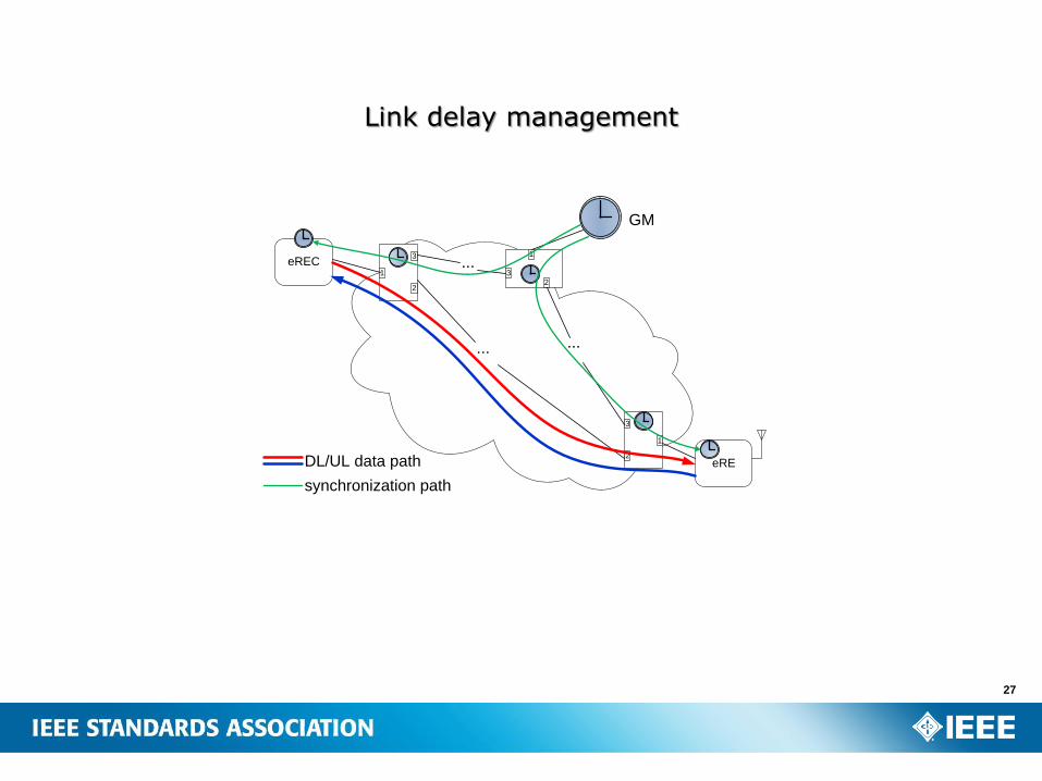
Link delay management
eREC
2
3
1
2
3
1
eRE
2
3
1
GM
... ...
...
DL/UL data path
synchronization path
28
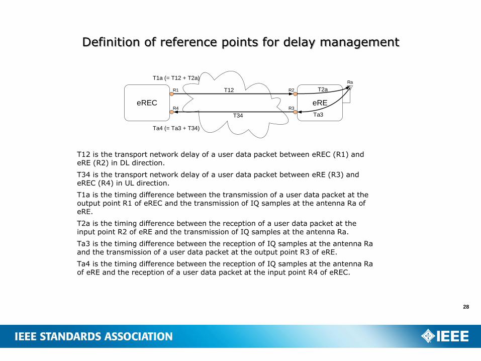
Definition of reference points for delay management
eREC eRE
T12
T34
T2a
Ta3
R1
Ra
R2
R4 R3
T1a (= T12 + T2a)
Ta4 (= Ta3 + T34)
T12 is the transport network delay of a user data packet between eREC (R1) and eRE (R2) in DL direction.
T34 is the transport network delay of a user data packet between eRE (R3) and eREC (R4) in UL direction.
T1a is the timing difference between the transmission of a user data packet at the output point R1 of eREC and the transmission of IQ samples at the antenna Ra of eRE.
T2a is the timing difference between the reception of a user data packet at the input point R2 of eRE and the transmission of IQ samples at the antenna Ra.
Ta3 is the timing difference between the reception of IQ samples at the antenna Ra and the transmission of a user data packet at the output point R3 of eRE.
Ta4 is the timing difference between the reception of IQ samples at the antenna Ra of eRE and the reception of a user data packet at the input point R4 of eREC.
Network connection maintenance and Network connection control is out of scope of the eCPRI specification. – There are a number of different methods and standards that
can be used.
For the Ethernet parts of eCPRI (if applicable for the User plane data and for IP over Ethernet), the Ethernet OAM can be used. – The IEEE 802.1ag Ethernet CMF (Connectivity Fault
Management) defines three protocols, Continuity Check Protocol (CCP), Link Trace (LT) and Loop-back (LB).
– ITU-T defines same things in Y.1731 by the Ethernet continuity check (ETH-CC), Ethernet link trace (ETH-LT) and Ethernet loopback (ETH-LB).
– Y.1731 also adds more OAM functions like Ethernet alarm indication signal (ETH-AIS), Ethernet remote defect indication (ETH-RDI) and Ethernet loss measurement (ETH-LM).
For the IP parts of the eCPRI (e.g. the C&M flow), the Internet Control Message Protocol (ICMP) can be used.
29
Network Connection Maintenance
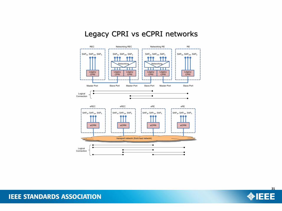
Legacy CPRI– Legacy CPRI is point-to-point interface in nature.– There is a master-port and a slave-port connected directly by optical/electrical cable(s) (a hop).– Networking functions are application layer functions and not supported by CPRI interface itself.– Supported topologies depend on REC/RE functions,– Supported logical connections include:
• Point-to-point (one REC – one RE).• Point-to-multi-point (one REC – several REs).
– Redundancy, QoS, security, etc. are REC/RE functions (if required).
eCPRI– An eCPRI network consists of eCPRI nodes (eRECs and eREs), transport network, as well as other network elements not
shown Figure 36 (including GM/BC for timing, EMS/NMS for management).– There is no longer a master port/slave port classification at physical level.
• SAPS: master of PTP and Synchronous Ethernet is not a eREC in general.• SAPCM: some of M-plane may be managed by EMS/NMS.
– The eCPRI layer is above the transport networking layer.– The eCPRI layer does not care about the actual transport network layer topology. – The transport network may include some local network, e.g. local switch(es) provided by the eREC/eRE vendors.– Supported logical connections include:
• Point-to-point (one eREC – one eRE), same as legacy CPRI.• Point-to-multi-point (one eREC – several eREs), same as legacy CPRI• Multi-point-to-multi-point (eRECs – eREs, eRECs – eRECs, eREs - eREs), new for eCPRI but not always necessary.
– Redundancy, QoS, security, etc. are mainly transport network functions; eCPRI nodes need to implement proper transport network layer protocols to support these capabilities if required.
30
eCPRI vs Legacy CPRI
31
Legacy CPRI vs eCPRI networks
Legacy
CPRI
SAPIQ, SAPCM, SAPS
Legacy
CPRI
Legacy
CPRI
SAPIQ, SAPCM, SAPS
Networking
Legacy
CPRI
Legacy
CPRI
SAPIQ, SAPCM, SAPS
Networking
Legacy
CPRI
SAPIQ, SAPCM, SAPS
Master Port Master Port Master PortSlave Port Slave Port Slave Port
Networking REC Networking REREC RE
Logical
Connection
transport network (front-haul network)
eCPRI
SAPUP SAPCM, SAPS
eREC
eCPRI
SAPUP SAPCM, SAPS
eREC
eCPRI
SAPUP SAPCM, SAPS
eRE
eCPRI
SAPUP SAPCM, SAPS
eRE
Logical
Connection
VLAN Tagging for Ethernet-switched fronthaul networks– For an Ethernet network with Ethernet bridges a VLAN tag according to the IEEE 802.1Q-2014
shall always be added by the eRE or eREC and provided to the Ethernet network. • The VLAN ID does not need to be set if only the priority is used in the VLAN tag. In that case the
VLAN ID (VID field) is set to zero (the null VID). The priority is set in the PCP field of the VLAN tag.
– Normally a C-tag with a priority in the PCP field is set by the eCPRI nodes (VID is optional), but other cases may exist depending on the network type and what kind of customer service interface to the network that is used.
– The use of the VLAN ID (VID field), including the null VID, is fully vendor specific and agreed with the network provider.
– How to use the priority field (PCP field) is vendor specific. See informative consideration below.
QoS for IP-routed fronthaul networks– QoS for IP-routed fronthaul network can be done by DiffServ.
• The DiffServ uses the DSCP field in the differentiated services field (DS field) in the IP header for classification purposes.
– How to use the DSCP field for QoS in an IP-routed fronthaul network is fully vendor specific.– Other ways to do QoS in an IP-routed fronthaul network are possible.
32
QoS
The User Plane Data and Real Time O&M data are the most time sensitive flows and normally require a high priority. – The traffic on the User Plane Data can in many cases be split into different
kind of traffic with different need of QoS. – In that case it might be good to have several priorities for the User Plane
Data.
The C&M data flow is normally not time sensitive and can be set to a low priority. – But it may be wise to have two different priorities for C&M. One with lower
priority than the User Plane Data and one with higher priority than the User Plane Data.
– The lower priority is used for normal C&M and the higher priority is used for critical operation or emergency that need to come through even if the User Plane Data overflow the available network bandwidth.
Note that for Ethernet-switched fronthaul network there are only up to eight priorities available and in a provider network other traffic might need at least one priority. – So even if there are a lot of traffic with different need of QoS (e.g. for the
User Plane Data) it will be good to keep down the total number of QoSlevels.
33
Priority considerations
User plane– User plane over IP– IPsec or MACsec are both optional solutions to provide transmission security. – User plane over Ethernet– MACsec is an optional solution to provide transmission security.
C&M plane– TLS, IPsec or MACsec are optional solutions to provide transmission security
and access control for eCPRI C&M plane.
Synchronization plane– Currently there are no security solutions available for the synchronization
plane.
Connection OAM plane– The eCPRI OAM plane is recommended to conform to the security
requirements of the OAM application and not enforce any additional security protection and processing.
34
eCPRI security