Embed Size (px)
Citation preview
1© Zetec Inc. All rights reserved
2019 A4A NDT Forum
Jesse Herrin
Eddy Current Array In Lieu of PT and MT for Aerospace Inspection
© Zetec Inc. All rights reserved
• Liquid Penetrant Testing (PT)• Magnetic Particle Testing (MT)• Eddy Current Testing (ECT)• Eddy Current Array Testing (ECA)• PT Aerospace Applications• MT Aerospace Applications• Conclusions
Agenda
2
© Zetec Inc. All rights reserved
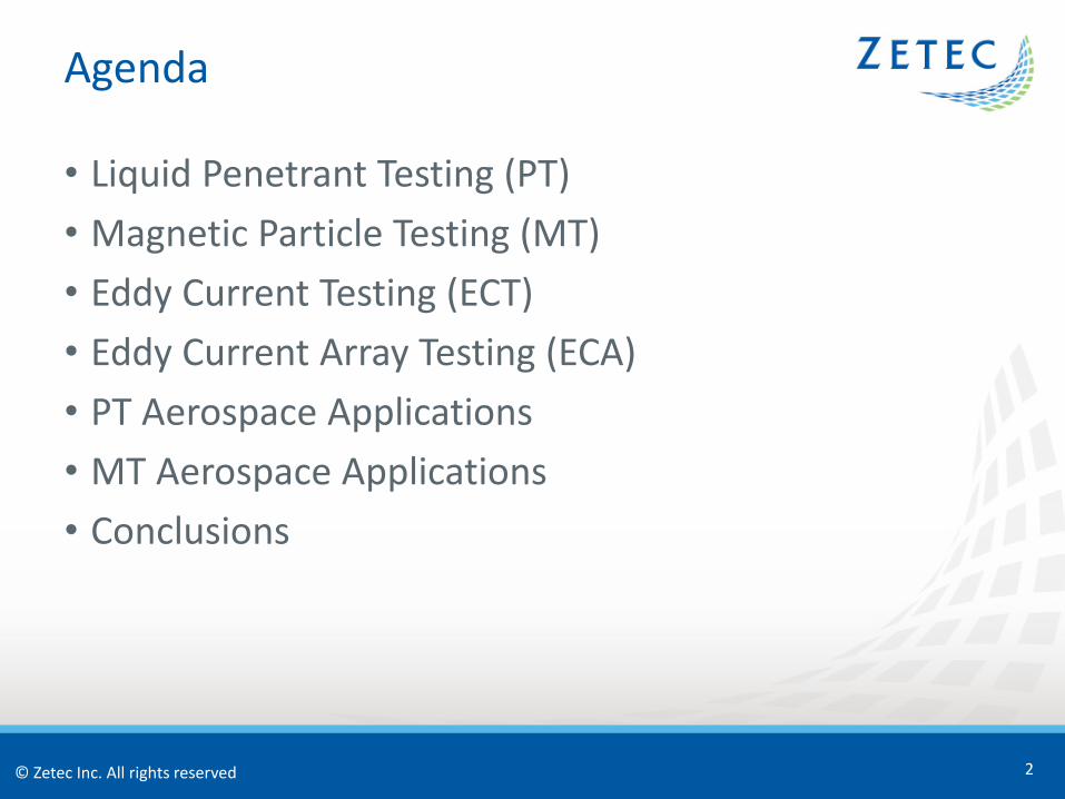
• Liquid or Dye Penetrant Testing (PT)• Liquid is drawn into surface openings by capillary action• Defects become visible from the dye or under UV light
• Identify surface-breaking defects and discontinuities in metal and other nonporous materials
Liquid Penetrant Testing (PT)
3
© Zetec Inc. All rights reserved
• Indication types:• Surface-Breaking Cracks and Discontinuities, Nicks, Cuts,
Gouges, Scratches, Corrosion
• Aerospace applications:• Structural parts – Multiple Materials, Bridges, Flanges,
Frames, Fuselage Parts, Supports, Ribs, Skins• Engine parts – Propellers, Turbine Rotor Blades, Nozzles,
Valves, Gear Boxes• Helicopter parts – Spars
Liquid Penetrant Testing (PT)
4
© Zetec Inc. All rights reserved
• Advantages:• Complex shapes can be tested• Conductive and nonconductive materials• Large numbers of similar parts can be rapidly
tested/automated• Small fine surface cracks can be detected• Estimate crack size• Easy to perform• Relatively low cost
Liquid Penetrant Testing (PT)
5
© Zetec Inc. All rights reserved
• Disadvantages:• Requires removal of paint and other coatings• Surface coatings can be hard to fully remove• Porous materials cannot be tested• Can’t detect subsurface indications that can hide just below
surface• Limitations at low and high temperature• Possibility of fire or explosion• Penetrants may be toxic or hazardous• Cleaning required after test• Requires reapplying paint or coatings to go back into service
Liquid Penetrant Testing (PT)
6
© Zetec Inc. All rights reserved
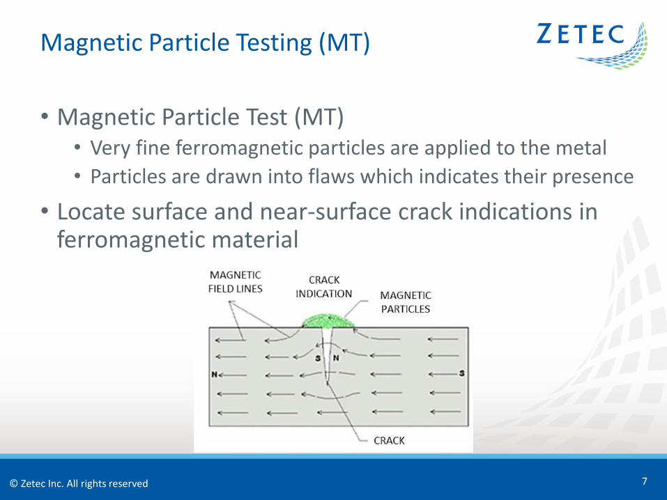
• Magnetic Particle Test (MT)• Very fine ferromagnetic particles are applied to the metal• Particles are drawn into flaws which indicates their presence
• Locate surface and near-surface crack indications in ferromagnetic material
Magnetic Particle Testing (MT)
7
© Zetec Inc. All rights reserved
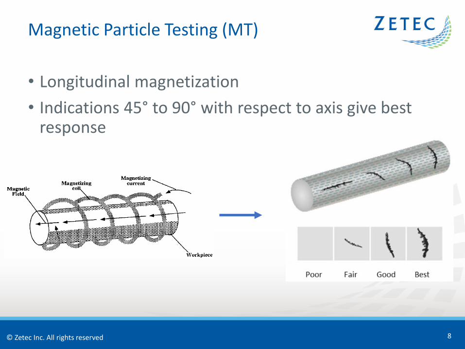
• Longitudinal magnetization• Indications 45° to 90° with respect to axis give best
response
Magnetic Particle Testing (MT)
8
© Zetec Inc. All rights reserved
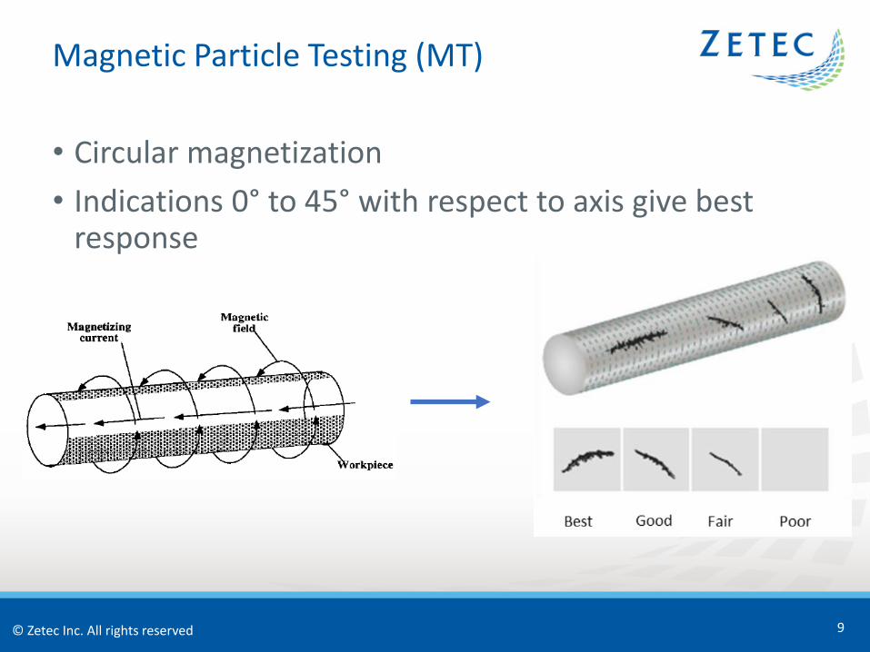
• Circular magnetization• Indications 0° to 45° with respect to axis give best
response
Magnetic Particle Testing (MT)
9
© Zetec Inc. All rights reserved
• Indication types:• Cracks, Laps, Seams, Inclusions, Other Discontinuities
• Aerospace applications:• Engine parts – Crankshafts, Connecting Rods, Engine
Mounts, Low Pressure Turbine Shafts, Gear Box Assemblies, Gear Reduction Components, Compressor Discs
• Structural parts – Under Carriage, Landing Gear• Other pats – Bolts, Nuts, Washers
Magnetic Particle Testing (MT)
10
© Zetec Inc. All rights reserved
• Advantages:• Complex shapes can be tested• Cracks filled with paint or other foreign material can be
detected• Large numbers of similar parts can be rapidly
tested/automated• Small fine cracks can be detected• Subsurface discontinuities can be located• Cracks can be located through thin nonmetallic coatings• Estimate crack depth• Easily learned• Relatively low cost
Magnetic Particle Testing (MT)
11
© Zetec Inc. All rights reserved
• Disadvantages:• Only ferromagnetic materials can be tested• High electric current required to magnetize• Demagnetization required in some instances• Extreme care to avoid burn spots• Difficult to detect small defects below the surface• Cleaning required after test• Complex shapes may require more than two magnetizations• Takes multiple magnetization orientations for full coverage
Magnetic Particle Testing (MT)
12
© Zetec Inc. All rights reserved
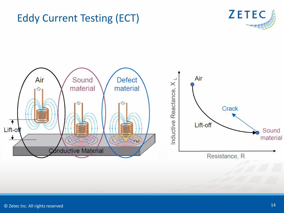
• Eddy Current Test (ECT)• Coils apply EM field into metal, indications disrupt EC flow• Can find indications in ferrous and non-ferrous materials• Detects through nonconductive coatings
• Generally no surface prep or chemicals are required• Computerized record of the inspection• There is high dependence on the user training• Speed is slow due to limitation of only inspecting one
spot at a time
Eddy Current Testing (ECT)
13
© Zetec Inc. All rights reserved
Eddy Current Testing (ECT)
14
© Zetec Inc. All rights reserved
Eddy Current Testing (ECT)
15
© Zetec Inc. All rights reserved
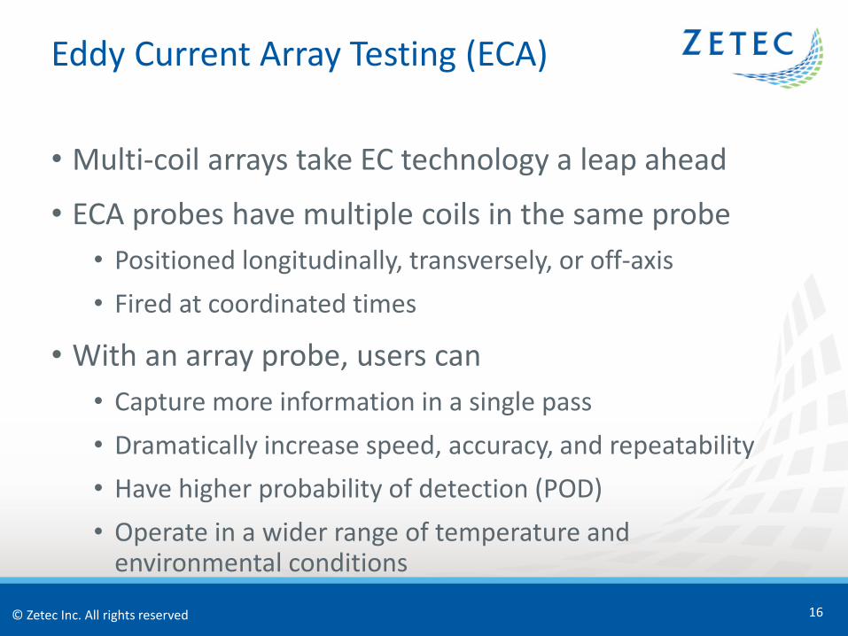
• Multi-coil arrays take EC technology a leap ahead
• ECA probes have multiple coils in the same probe• Positioned longitudinally, transversely, or off-axis• Fired at coordinated times
• With an array probe, users can• Capture more information in a single pass• Dramatically increase speed, accuracy, and repeatability• Have higher probability of detection (POD)• Operate in a wider range of temperature and
environmental conditions
Eddy Current Array Testing (ECA)
16
© Zetec Inc. All rights reserved
Eddy Current Array Testing (ECA)
17
32161
R
R
T
R
R
R
T
R
R
R
T
R
R
R
T
R
R
R
T
R
R
R
T
R
R
R
T
R
R
R
T
R
R
R
T
R
R
R
T
R
R
R
T
R
R
R
T
R
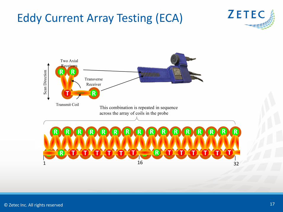
This combination is repeated in sequence across the array of coils in the probe
Transmit Coil
T
TransverseReceiver
R
Two Axial Receivers
RR
Scan
Dire
ctio
n
© Zetec Inc. All rights reserved
TAM Panel PT Details
18
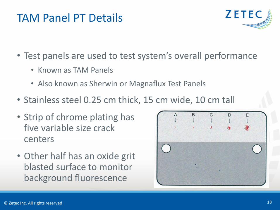
• Test panels are used to test system’s overall performance• Known as TAM Panels
• Also known as Sherwin or Magnaflux Test Panels
• Stainless steel 0.25 cm thick, 15 cm wide, 10 cm tall
• Strip of chrome plating has five variable size crack centers
• Other half has an oxide grit blasted surface to monitor background fluorescence
© Zetec Inc. All rights reserved
TAM Panel PT Inspection Challenges
19
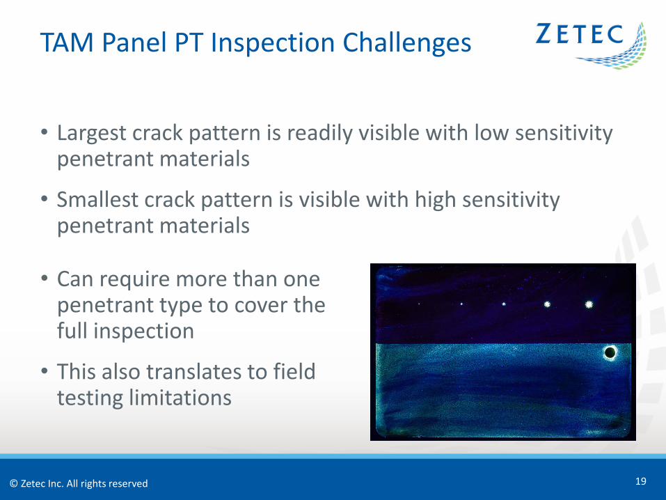
• Largest crack pattern is readily visible with low sensitivity penetrant materials
• Smallest crack pattern is visible with high sensitivity penetrant materials
• Can require more than one penetrant type to cover the full inspection
• This also translates to field testing limitations
© Zetec Inc. All rights reserved
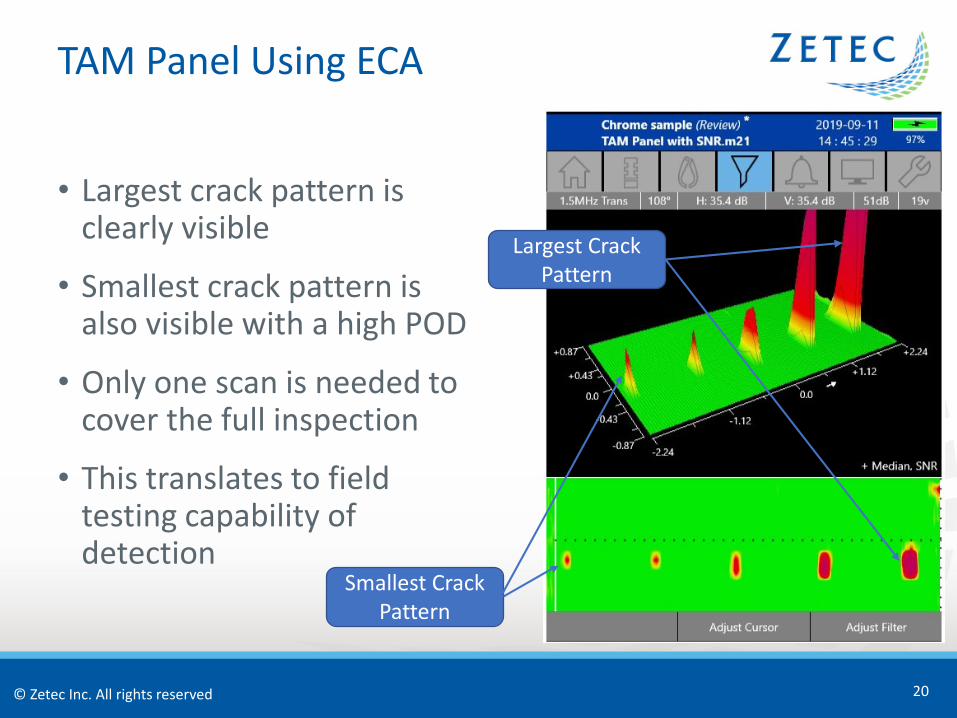
TAM Panel Using ECA
20
• Largest crack pattern is clearly visible
• Smallest crack pattern is also visible with a high POD
• Only one scan is needed to cover the full inspection
• This translates to field testing capability of detection
Largest Crack Pattern
Smallest Crack Pattern
© Zetec Inc. All rights reserved
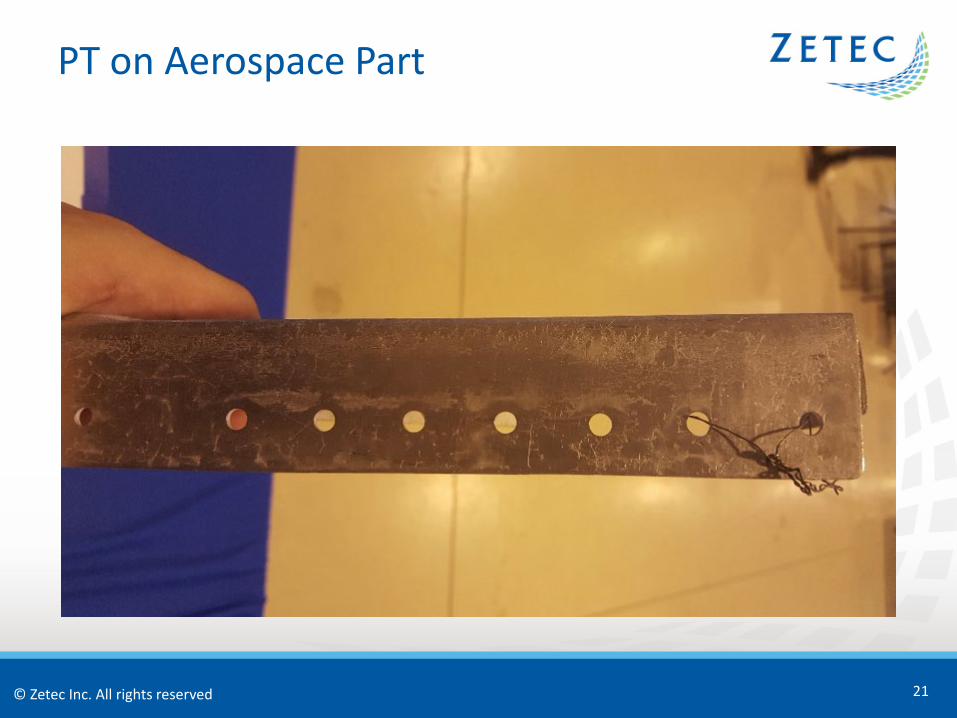
PT on Aerospace Part
21
© Zetec Inc. All rights reserved
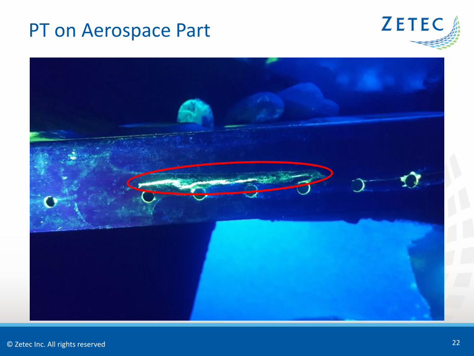
PT on Aerospace Part
22
© Zetec Inc. All rights reserved
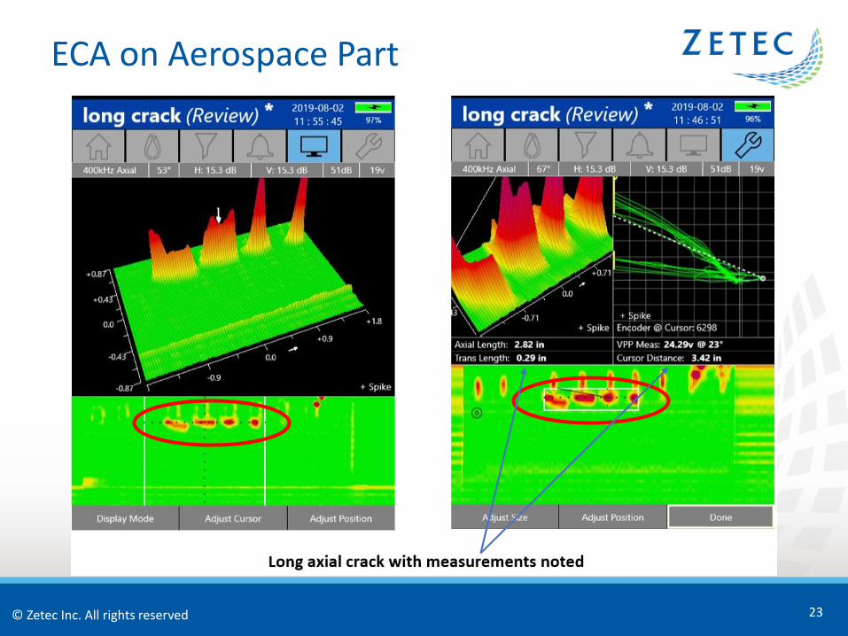
ECA on Aerospace Part
23
© Zetec Inc. All rights reserved
Surface Crack at Rivet Hole PT Details
24
• PT is often used to find surface indications around aerospace rivets in skins, stringers, and other structural parts
• In parts that have paint or other coatings they must be stripped to get to the surface of the base material
• The chemical stripping process can be ineffective in removing all organic and inorganic surface coatings
© Zetec Inc. All rights reserved
Surface Crack at Rivet Hole Challenges
25
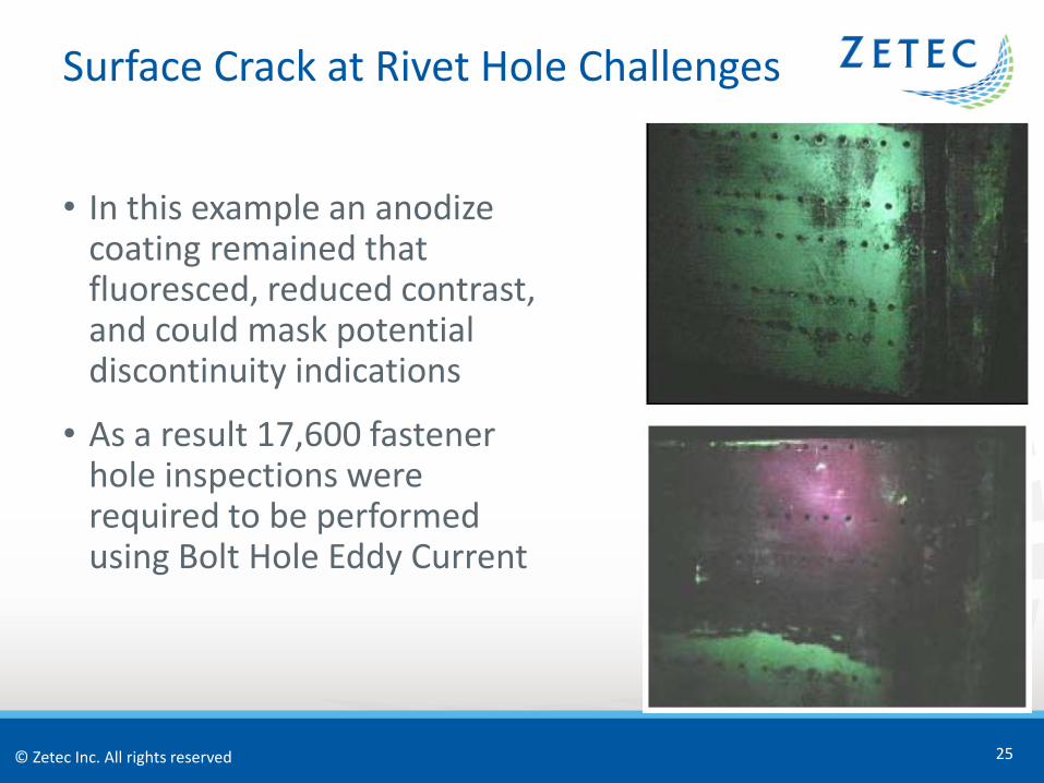
• In this example an anodize coating remained that fluoresced, reduced contrast, and could mask potential discontinuity indications
• As a result 17,600 fastener hole inspections were required to be performed using Bolt Hole Eddy Current
© Zetec Inc. All rights reserved
Surface Crack at Rivet Hole Using ECA
26
© Zetec Inc. All rights reserved
Surface Crack at Rivet Hole Using ECA
27
© Zetec Inc. All rights reserved
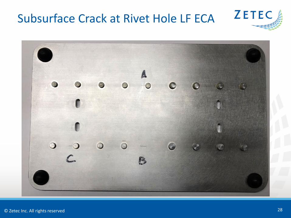
Subsurface Crack at Rivet Hole LF ECA
28
© Zetec Inc. All rights reserved
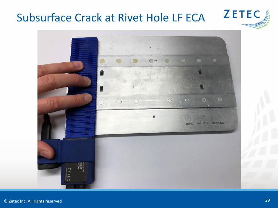
Subsurface Crack at Rivet Hole LF ECA
29
© Zetec Inc. All rights reserved
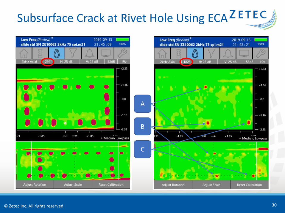
Subsurface Crack at Rivet Hole Using ECA
30
A
B
C
© Zetec Inc. All rights reserved
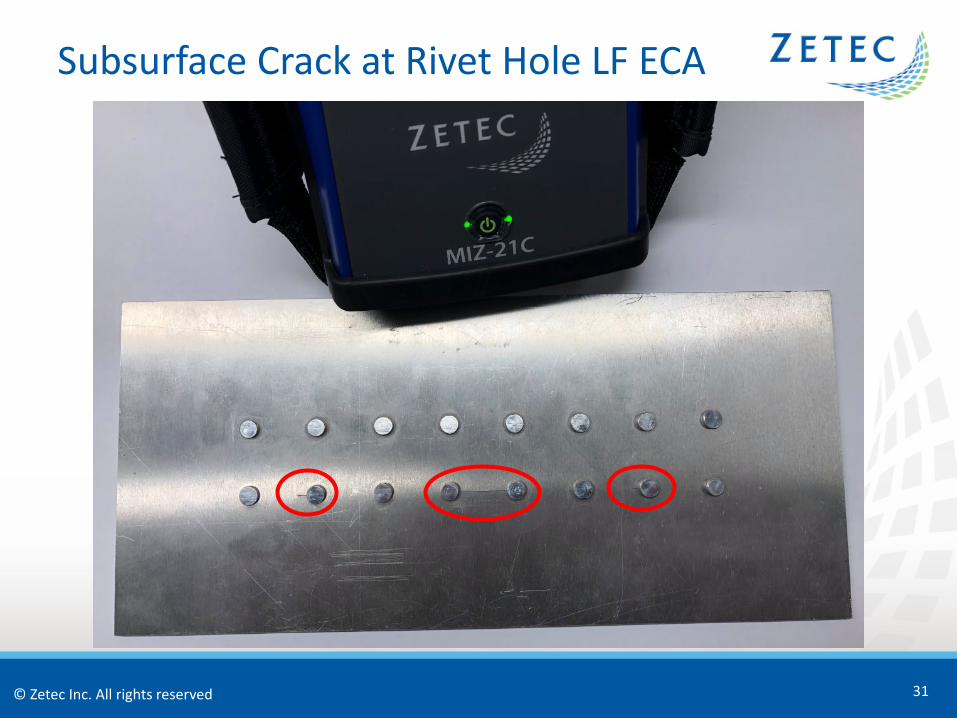
Subsurface Crack at Rivet Hole LF ECA
31
© Zetec Inc. All rights reserved
Subsurface Crack at Rivet Hole LF ECA
32
© Zetec Inc. All rights reserved
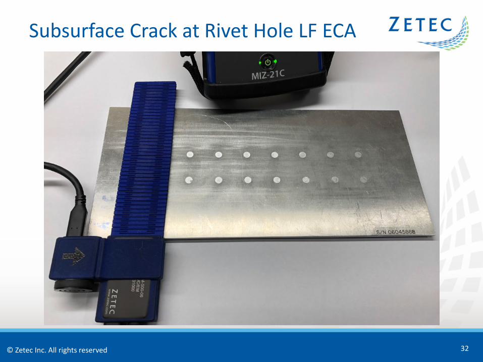
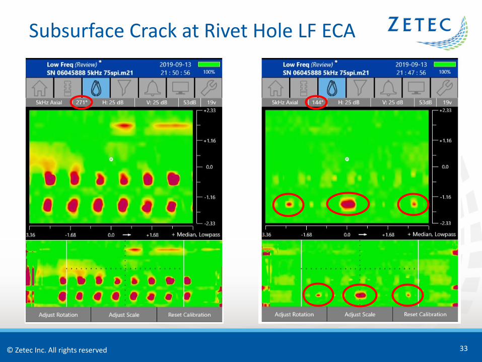
Subsurface Crack at Rivet Hole LF ECA
33
© Zetec Inc. All rights reserved
Ferrous Parts MT Details
34
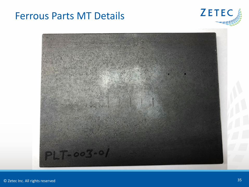
• Carbon Steel material
• Aerospace parts include: • Engine parts – Crankshafts, Connecting Rods, Engine
Mounts, Low Pressure Turbine Shafts, Gear Box Assemblies, Gear Reduction Components, Compressor Discs
• Structural parts – Under Carriage, Landing Gear
© Zetec Inc. All rights reserved
Ferrous Parts MT Details
35
© Zetec Inc. All rights reserved
Ferrous Parts MT Challenges
36
• Often MT can be required by manufacturer procedures
• MT can require the removal of paint and other non-conductive coatings to perform the inspection
• It’s a time consuming process that is highly dependent on the skill of the inspector and includes the handling and disposal of chemicals
• MT has limited ability to record data files and provide that traceability
• Inspection traceability is becoming more critical with the liabilities associated with aerospace component failure
© Zetec Inc. All rights reserved
Ferrous Parts Using ECA
37
• Can quickly inspect large ferrous surface areas through paint and other non-conductive coatings without removal
• Has limited influence by the inspector’s skill
• Can conform to complex geometries using highly flexible thin film printed coils
• Can provide recorded data traceability
© Zetec Inc. All rights reserved
Propeller Bolts MT Details
38
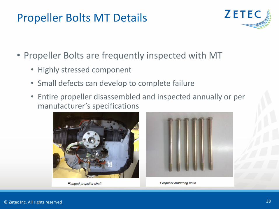
• Propeller Bolts are frequently inspected with MT• Highly stressed component
• Small defects can develop to complete failure
• Entire propeller disassembled and inspected annually or per manufacturer’s specifications
© Zetec Inc. All rights reserved
Propeller Bolts MT Challenges
39
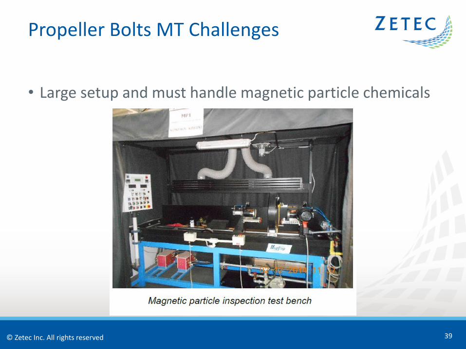
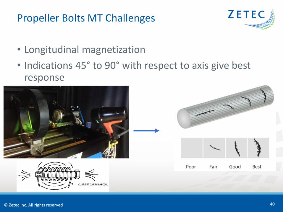
• Large setup and must handle magnetic particle chemicals
© Zetec Inc. All rights reserved
• Longitudinal magnetization• Indications 45° to 90° with respect to axis give best
response
Propeller Bolts MT Challenges
40

© Zetec Inc. All rights reserved
• Circular magnetization• Indications 0° to 45° with respect to axis give best
response
Propeller Bolts MT Challenges
41
© Zetec Inc. All rights reserved
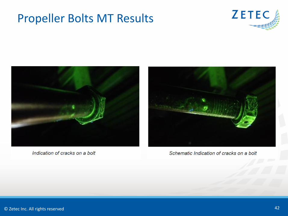
Propeller Bolts MT Results
42
© Zetec Inc. All rights reserved
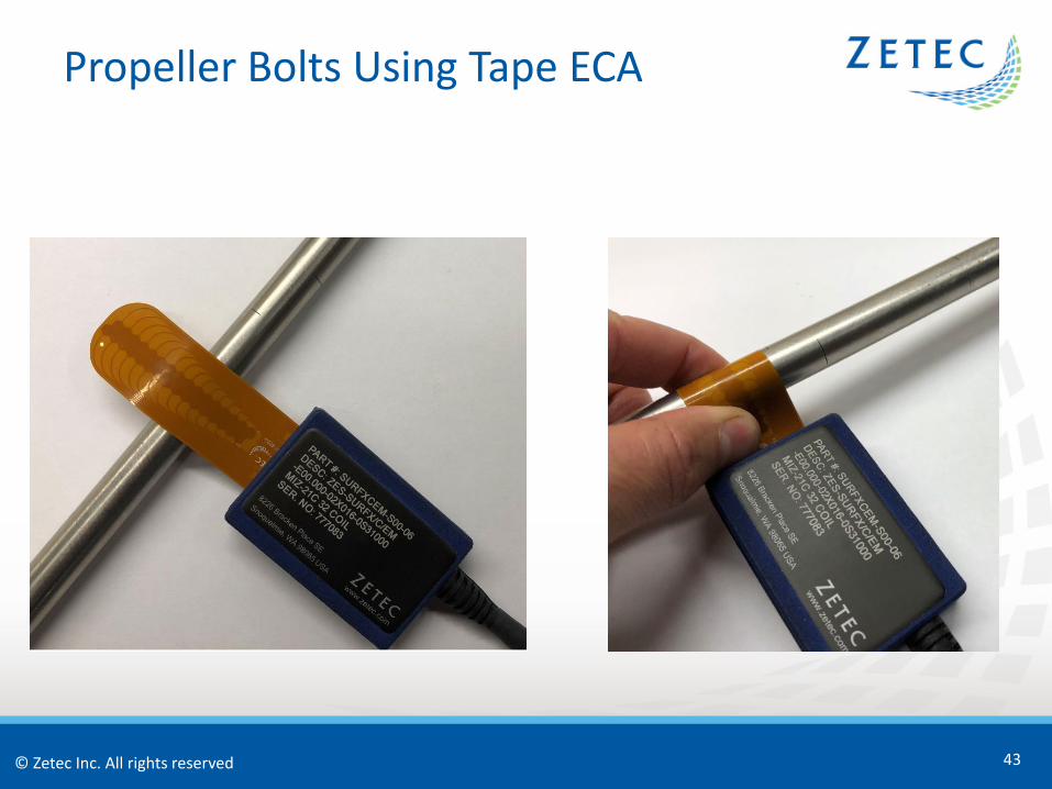
Propeller Bolts Using Tape ECA
43
© Zetec Inc. All rights reserved
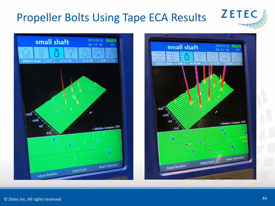
Propeller Bolts Using Tape ECA Results
44
© Zetec Inc. All rights reserved
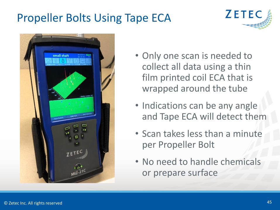
Propeller Bolts Using Tape ECA
45
• Only one scan is needed to collect all data using a thin film printed coil ECA that is wrapped around the tube
• Indications can be any angle and Tape ECA will detect them
• Scan takes less than a minute per Propeller Bolt
• No need to handle chemicals or prepare surface
© Zetec Inc. All rights reserved
Conclusions• PT and MT have their advantages, but there are number of
disadvantages that makes them suitable candidates for replacement with ECA
• ECA can find large and small indications in one scan and avoids having to use separate exams for low and high sensitivity penetrant materials
• During surface crack inspections around rivet holes paint does not need to be removed when using ECA, and if a Low Frequency ECA is used the subsurface indications can also be found
• ECA is capable of replacing many ferrous material MT surface inspections
• Propeller Bolts can quickly be inspected in one pass with ECA Tape Probes that have thin film printed coils that allow for small bend radius
• ECA can operate in a wider range of temperature and environmental conditions than PT and MT, in most cases has a higher POD, and can greatly improve productivity
46
© Zetec Inc. All rights reserved
References
• P. Vijayaraghavan, “Magnetic Particle & Penetrant Inspection of Aerospace Components During Manufacture & Service”, The e-Journal of Nondestructive Testing 20, 1-6, (June 2015).
• NASA Preferred Reliability Practices, “Penetrant Testing of Aerospace Materials”, Practice No. PT-TE-1426, 1-6.
• NASA Preferred Reliability Practices, “Magnetic Particle Testing of Aerospace Materials”, Practice No. PT-TE-1425, 1-5.
• A Uludag, “The Magnetic Particle Inspection Examination of Aircraft Propeller Mounting Bolts”, Journal of Multidisciplinary Engineering Science and Technology 3, 1-5, (December 2016).
• L. Culbertson, “Eddy Current Inspection Conventional to Array”, 2017 A4A NDT Forum, 1-50, (September 2017).
47
© Zetec Inc. All rights reserved
Thank You
Questions?
48