Embed Size (px)
Citation preview

IEEE TRANSACTIONS ON MAGNETICS, VOL. 42, NO. 3, MARCH 2006 405
Eddy-Current Coupling With Slotted Conductor DiskHamideh K. Razavi and Michael U. Lampérth
Hybrid Power Research Group, Department of Mechanical Engineering, Imperial College London, London SW7 2AZ, U.K.
Eddy-current couplings are becoming popular devices for speed and torque control. Efficiency of these couplings depends on the ex-citation level; therefore, the routes and density of induced currents affect it significantly. This paper focuses on the design of a squirrelcage-type coupling disk, which forces eddy currents to flow perpendicular to both magnetic field lines and the axis of rotation. Lorentzforce and transmitted torque are consequently optimized. The investigation is performed both numerically and experimentally, withresults being presented for variable air gaps and speeds. A comparison between plain and slotted disk conductors, tested under identicalset-ups, demonstrates the effect of the proposed design on torque throughput and efficiency. In addition to this, the influence of numberand size of slots and the effect of filling slots with iron are studied by parametric finite-element modeling verified by experiments.
Index Terms—Conductor design, eddy-current coupling, finite-element analysis.
I. INTRODUCTION
PERMANENT-magnet eddy-current couplings (PMECs)have become commercially available since 1999 [1].
Initially employed to replace conventional variable frequencydrives (VFDs) in fans and pumps, eddy-current adjustablespeed coupling systems (ASCSs) were promptly recognized bydiverse industries [2].
An ASCS consists of a double face magnetic stator, whichcan spin inside a rotor housing with conductor disks positionedon both sides. A screw mechanism enables speed control byaxial movement of the magnet disks and adjustment of the airgaps. As the motor shaft starts rotation, a time-variant magneticexcitation occurs on the conductor disks. Induced eddy currentswithin the skin depth of the conductors generate a tangentialforce and hence a reactive torque on the stator of the coupling.
In spite of the lower efficiency of an ASCS (93%) comparedto that of a VFD (95%) [3], it has remarkable advantages suchas simplicity and compact design as well as economic tradeoffs.
In order to enhance the efficiency of an ASCS, stray currents,generated in the conductor disk, should be eliminated. Thesecurrents end in ohmic losses by generating heat in the conductordisk [4]. Generated heat not only wastes energy but also disturbsthe magnetic properties of the permanent magnets, which in turnreduces the torque-transmitting capability of the system.
This paper presents a new design of the conductor disk withslot cuts that facilitates the flow of currents in appropriate routesin order to avoid stray currents. Precise performance analysis ofPMECs attributed to three-dimensional (3-D) electromagneticfield effects is only possible if a 3-D numerical technique is used[5]–[7]. However, using linear theory, analytical approximationfor simplified two-dimensional (2-D) models, representing 3-Dmodels, are viable. By this method, models are solved in lesstime and are less costly, and results are highly credible.
In this research, initially a 2-D numerical model for a plainconductor disk with the equivalent geometry is solved. Com-paring the results to those of experiments validates the model to
Digital Object Identifier 10.1109/TMAG.2005.862762
Fig. 1. Schematic of the coupling.
be refined for slotted design. To avoid complicated electromag-netic field analysis, an elementary approach is implemented. Itconcludes that a slotted copper disk improves pull-out torqueby 15%. Additionally an iron-backing disk with bulges, whichcan plug into the slot gaps in the conductor disk, boosts the fluxdensity in the region and amplifies the results.
II. GENERAL DESIGN
A magnet rotor with an even number of alternative pole em-bedded magnets is used. The spider plate is made of aluminumand the magnets are sintered Nd–Fe–B with residual induction
G (Fig. 1).A plain copper disk is fixed on an iron backing plate of 4 mm
thickness and forms the stator part of the coupling. Table I in-cludes other specifications of the coupling.
To make a 2–D representation of a slice, containing two adja-cent magnets, a radial view of the magnet pitch circle is unrolledas shown in Fig. 2.
In Fig. 2, the length of the arcs BD and DF are
and (1)
where
(2)
(3)
0018-9464/$20.00 © 2006 IEEE

406 IEEE TRANSACTIONS ON MAGNETICS, VOL. 42, NO. 3, MARCH 2006
TABLE ICOUPLING SPECIFICATIONS
Fig. 2. Geometry of the 2–D imaging.
Fig. 3. Field map on a 2–D linear model.
Other parameters are
(4)
(5)
is the number of magnets and is magnet pitch circleradius.
The field map in Fig. 3 shows how the flux density is con-centrated in and around the magnet projection zone on the con-ductor face. This can be modeled by an exponential waveform(cumulative sinusoidal term) [8], [9]. However, in this study, adistribution with a mutual sinusoidal general term is employed
Fig. 4. Magnetic flux density on the surface of the copper as a function of '.
[10]. It allows a region with zero flux density along each period(depicted in Fig. 4) which helps analysis in the next step.
Fourier expression of the magnetic flield forand will hence become
(6)
with coefficients
(7)
(8)
where is the deflection angle and is the number of har-monics. The new equation (6) also resolves the displacementof the peak flux density from the magnet core positions. There-fore, eddy-current density and dispersion over conductive sur-faces will be determined more accurately.
An identical 2-D model to that in Fig. 2 was constructed inthe finite-element (FE) environment and solved using transientmotion analysis with heat loss consideration. Data input for themagnetic field were collected by solving (6) along the axis ofthe 2-D imaging model in Fig. 2.
Fig. 5 illustrates the experimental results as well as the torquefeatures obtained by FE analysis. The reasonable match betweenresults justifies the model for the next step.
A plot of the eddy currents on the surface of the conductor isdepicted in Fig. 6. It suggests that whereas only radial segmentsof each vortex contribute to the drag force, deflection is mainlytangential. A remedy to this disarray is to eliminate presenceof conducting material physically and force currents to flow inradial routes.
III. SLOTTED CONDUCTOR
Using parametric modeling of the FE analysis, a range ofsizes and numbers of the slot cuts for the conductor disk wastested. Fig. 7 shows a 3-D image and Table II contains geome-tries of the samples.
Radial length of eddy-current formation on the conductorface has been regarded for cutting dimensions [11], [12].

RAZAVI AND LAMPÉRTH: EDDY-CURRENT COUPLING WITH SLOTTED CONDUCTOR DISK 407
Fig. 5. Comparison between numerical and experimental results (2 mmair gap).
Fig. 6. Eddy-current plot on the conductor.
Fig. 7. 3-D image of slotted copper disk.
TABLE IISLOTTED CONDUCTORS
To calculate the effective length of the slot in the verticalmagnetic field, a simple geometrical method is employed. Inany time instant , position of the slot cut against magnet
Fig. 8. Slot cuts projection on the rotor disk.
can be described either as an offset angle or linear distancedenoted by (see Fig. 8), where
for
OtherwiseNumber of slots (9)
Number of magnets
(10)
and is the first offset (can be assumed zero). and are thesame as in Fig. 2.
Chord BE in Fig. 8 represents the effective length . It canbe seen that
(11)
and
(12)
Since
(13)
by finding from (13) and substituting in (12), isobtained:
(14)
Also from Fig. 8, for the angle equal to we have
(15)
408 IEEE TRANSACTIONS ON MAGNETICS, VOL. 42, NO. 3, MARCH 2006
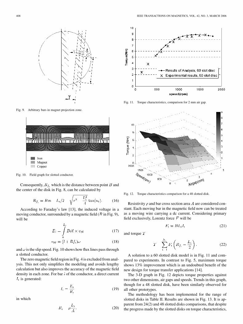
Fig. 9. Arbitrary bars in magnet projection zone.
Fig. 10. Field graph for slotted conductor.
Consequently, which is the distance between point andthe center of the disk in Fig. 8, can be calculated by
(16)
According to Faraday’s law [13], the induced voltage in amoving conductor, surrounded by a magnetic field ( in Fig. 9),will be
(17)
(18)
and is the slip speed. Fig. 10 shows how flux lines pass througha slotted conductor.
The zero magnetic field region in Fig. 4 is excluded from anal-ysis. This not only simplifies the modeling and avoids lengthycalculation but also improves the accuracy of the magnetic fielddensity in each zone. For bar of the conductor, a direct current
is generated:
(19)
in which
(20)
Fig. 11. Torque characteristics, comparison for 2 mm air gap.
Fig. 12. Torque characteristics comparison for a 48 slotted disk.
Resistivity and bar cross section area are considered con-stant. Each moving bar in the magnetic field now can be treatedas a moving wire carrying a dc current. Considering primaryfield exclusively, Lorentz force will be
(21)
and torque
(22)
A solution to a 60 slotted disk model is in Fig. 11 and com-pared to experiments. In contrast to Fig. 5, maximum torqueshows 13% improvement which is an undoubted benefit of thenew design for torque transfer applications [14].
The 3-D graph in Fig. 12 depicts torque properties againsttwo other dimensions, air gaps and speeds. Trends in this graph,though for a 48 slotted disk, have been similarly observed forall other prototypes.
The methodology has been implemented for the range ofslotted disks in Table II. Results are shown in Fig. 13. It is ap-parent from 24(2) and 48 slotted disks comparisons, that despitethe progress made by the slotted disks on torque characteristics,

RAZAVI AND LAMPÉRTH: EDDY-CURRENT COUPLING WITH SLOTTED CONDUCTOR DISK 409
Fig. 13. Torque characteristics comparison for 2 mm air gap (Dashed linesinterpolate groups of data).
Fig. 14. Back iron plate with protrusions.
a compromise exists between the number and width of the slots.Taking into account the complexity of the manufacturing, theoptimization of the slot size and numbers need to be rigorousfor each particular application [15].
IV. SLOTTED CONDUCTOR FILLED WITH IRON
Filling slots with iron reduces the air gap and increases theflux density in the region. For this purpose, iron-backing plates,as shown in Fig. 14, with slot shape protrusions were made. Bythis revision, the magnetic field is stronger between conductorbars, similar to Fig. 15. Moreover, higher gradients over timegenerate a considerable boost on torque measures.
Table III summarizes the effect of iron in slots obtained fromexperiments. An average increase of 50% is achievable by usinga protruded iron disk. Detailed results for torque figures of a 48slotted disk are shown in Fig. 16. In this case, at 1200 rpm a47% increase to plain conductor results is obtained.
Hysteresis and end leakage have more influence when ironis used in slots. This was clearly sensed by a torque transducermounted on the shaft while testing at different speeds. Slow ac-celeration and high frequency of speed alterations intensifies theeffects and causes immediate drop down in torque responses.
V. CONCLUSION
A new design for the conductor disk of an axial flux eddy-current coupling is presented in this paper. In order to analyze
Fig. 15. Field map for coupling with iron filled slotted conductor.
Fig. 16. Torque characteristics comparison for 2 mm air gap.
TABLE IIIAVERAGE INCREASE IN TORQUE MEASURES FOR IRON FILLED
SLOTTED CONDUCTORS
the performance of the coupling and compare it to its generaldesign, a 2-D FE model was developed. Comparing analyticalresults to those of experiments reveals that the 2-D model isreliable. The methodology is based on linear theory with minormodifications in the magnetic field distribution.
Computing the new magnetic field quantities requires a sepa-rate analytical solution. Although this calculation is straightfor-ward, it interrupts the FE analysis and hence increases the totalsolution time. This is predominantly due to the need to insert theresults manually into the model. These modifications enable theanalysis of the new coupling design in 2-D whereas normally afull 3-D solution will be required.
The results of experiments and analysis proved that a cou-pling with a slotted conductor transfers higher torque than itdoes with a conventional plain conductor. Therefore, a varietyof the slotted designs including slot cuts packed with iron wasstudied. It is inferred that the maximum number of slots is notnecessarily the optimum since adequate material must exist tocarry generated currents. As a result, a compromise betweenthe width and number of bars is inevitable. Axial loads and
410 IEEE TRANSACTIONS ON MAGNETICS, VOL. 42, NO. 3, MARCH 2006
heat exchange characteristics of the new design are still to beinvestigated.
ACKNOWLEDGMENT
This work was supported by Imperial College London.
REFERENCES
[1] C. Smith, S. Williamson, A. Benhama, L. Counter, and J. M. Pa-padopoulos, “Magnetic drive couplings,” in Proc. IEE Ninth EMDConf., Sep. 1999, pp. 232–236.
[2] A. Wallace and A. Jouanne, “Industrial speed control: Are PM couplingsan alternative to VFDs?,” IEEE Ind. Appl. Mag., pp. 57–63, Sep./Oct.2001.
[3] A. Wallace, A. von Jouanne, R. Jeffreys, E. Matheson, and X. Zhaou,“Comparison testing of an adjustable-speed permanent magnet cou-pling,” in IEEE Pulp & Paper Industry Technical Conf., Atlanta, GA,Jun. 2000.
[4] M. U. Lamperth, “An investigation into the mechanical and electricallosses of permanent magnet disc machines,” Ph.D. thesis, Dept. Mech.Eng., Imperial College London, London, U.K., Sep. 2000.
[5] W. Wu, H. C. Lovatt, and J. B. Dunlop, “Analysis and design optimiza-tion of magnetic couplings using 3D finite element modeling,” IEEETrans. Magn., vol. 33, no. 5, pp. 4083–4085, Sep. 1997.
[6] S. Sunneriniemi, K. Forsman, L. Kettunen, and J. Makinen, “Computa-tion of eddy currents coupled with motion,” IEEE Trans. Magn., vol. 36,no. 4, pp. 1341–1345, Jul. 2000.
[7] S. L. Ho, S. Yang, G. Ni, H. C. Wong, and Y. Wang, “Numerical analysisof thin skin depths of 3-D eddy-current problems using a combinationof finite element and meshless methods,” IEEE Trans. Magn., vol. 40,no. 2, pp. 1354–1357, Mar. 2004.
[8] A. Canova and B. Vusini, “Design of axial eddy-current couplers,” IEEETrans. Ind. Appl., vol. 39, no. 3, pp. 725–733, May/Jun. 2003.
[9] Z. J. Liu, A. Vourdas, and K. J. Binnis, “Magnetic field and eddy currentlosses in linear and rotating permanent magnet machines with a largenumber of poles,” IEE Proc. A, vol. 138, no. 6, pp. 289–294, Nov. 1991.
[10] S. Uzunbajakau, A. P. Rijpma, J. Dolfsma, H. J. G. Krooshoop, H. J.M. ter Brake, M. J. Peters, and H. Rogalla, “Magnetic flux fluctuationsdue to eddy currents and thermal noise in metallic disks,” IEEE Trans.Magn., vol. 39, no. 4, pp. 2018–2023, Jul. 2003.
[11] S. B. Hughes, “Magnetic braking: Finding the effective length overwhich the eddy currents form,” The College of Wooster Research Paper44691, May 2000.
[12] D. Rodger, H. C. Coles, and R. J. Hill-Cottingham, “Modeling axialairgap induction machines,” in IEE Seminar on Axial Airgap Machines(Ref no. 2001/157), May 2001, pp. 2/1–2/3.
[13] H. Gholizad, M Mirsalim, M. Mirzayee, and I. A. Tsukerman, “Mo-tional eddy currents analysis in moving solid iron using magnetic equiv-alent circuits method,” in IEEE/ACES Int. Conf. Wireless Communica-tions and Applied Computational Electromagnetics, Apr. 3–7, 2005, pp.533–536.
[14] H. Razavi, M. Lamperth, and P. Anpalahn, “Eddy current couplings formild hybrid trucks,” SAE Tech. Papers, 2003-01-3382.
[15] , “Application of an axial flux eddy current coupling in a mild hy-brid powertrain,” in 20th Int. Electric Vehicle Symp., 2003, EVS 20.
Manuscript received October 15, 2004; revised November 27, 2005 (e-mail:[email protected]).
Hamideh K. Razavi is a Researcher in transmission technology in hybridpower-trains. Her former studies were on manufacturing with a broad experi-ence in automotive industries.
Michael U. Lampérth is Lecturer of design, CAD, electronics and instrumen-tation in the Mechanical Engineering Department of Imperial College London,London, U.K. He is head of the hybrid power research group, which focuses onsustainable energy technologies, hybrid electric vehicles, including simulationand permanent-magnet machines.