Embed Size (px)
Citation preview
TELTONIKA
EDGE camera (MVC100)
User’s Manual 1.15a
2 | P a g e
LEGAL NOTICE
Copyright © 2010 TELTONIKA Ltd. All rights reserved. Reproduction, transfer, distribution or storage of part or all of the contents in this document in any form without the prior written permission of TELTONIKA Ltd is prohibited.
Other product and company names mentioned herein may be trademarks or trade names of their respective owners.
CE COMPLIANCE
This equipment has been tested and found to comply with the limits for a Class B digital device. CE mark declaration of conformity can be found at Teltonika WEB page www.teltonika.eu
Standards applied:
LST EN 60950-1:2003
LST EN 301 489-1 V1.8.1:2008
LST EN 55022:2007+A1:2008
LST EN 61000-4-2+A1+A2:2002
LST EN 61000-4-3:2006
LST EN 61000-4-4:2005
LST EN 61000-4-5:2007
LST EN 61000-4-6:2007
LST EN 61000-4-11:2004
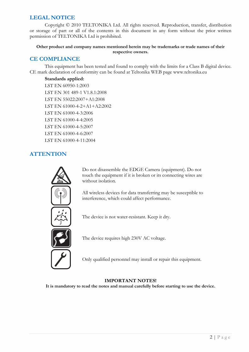
ATTENTION
Do not disassemble the EDGE Camera (equipment). Do not touch the equipment if it is broken or its connecting wires are without isolation.
All wireless devices for data transferring may be susceptible to interference, which could affect performance.
The device is not water-resistant. Keep it dry.
The device requires high 230V AC voltage.
Only qualified personnel may install or repair this equipment.
IMPORTANT NOTES! It is mandatory to read the notes and manual carefully before starting to use the device.

3 | P a g e
ACRONYMS
AC/DC Alternating Current/Direct Current APN Access Point Name CCT Camera connection tool CD Compact disc CHAP Challenge Handshake Authentication Protocol DDNS Dynamic Domain Name System DNS Domain Name System EDGE Enhanced Data rates for GSM Evolution FTP File Transfer Protocol GND Ground GPIO General Purpose Input Output GPRS General Packet Radio Service GSM Global System for Mobile communications IMEI International Mobile Equipment Identity IRLED Infrared LED ISP Internet Service Provider JPEG Joint Photographic Experts Group L Line LED Light Emitting Diode MPEG Motion Picture Experts Group N Neutral NiMH Nickel-metal hydride OS Operating System PAP Password Authentication Protocol PC Personal computer PDP Packet Data Protocol PE Protective earth PIN Personal Identification Number PPP Point-to-Point Protocol QQVGA Quarter-QVGA QVGA Quarter VGA Rx Receive SIM Subscriber Identity Module SMS Short Message Service SW Software TCP/IP Transmission Control Protocol/Internet Protocol Tx Transmit UART Universal Asynchronous Receiver/Transmitter USB Universal Serial Bus VGA Video Graphics Array WEB World Wide Web
4 | P a g e
Table of Contents
1 SAFETY INFORMATION .................................................................................................................... 5
2 GETTING STARTED ............................................................................................................................ 7
2.1 Introduction ....................................................................................................................................................... 7
2.2 Package contents ............................................................................................................................................... 7
2.3 Installing the hardware ...................................................................................................................................... 7 2.3.1 Inserting SIM card ............................................................................................................................................ 7 2.3.2 Attaching antenna ............................................................................................................................................ 8 2.3.3 Back panel overview ........................................................................................................................................ 8 2.3.4 2-pin terminal block ......................................................................................................................................... 9 2.3.5 5-pin terminal block ......................................................................................................................................... 9 2.3.6 Wall mounting .................................................................................................................................................. 9
2.4 Camera access software and drivers ................................................................................................................ 10 2.4.1 Installing the software and drivers (Windows XP only) ................................................................................. 10 2.4.2 Connecting to the EDGE Camera with Camera Connection Tool (CCT) ......................................................... 11 2.4.3 Configuring the camera with Configuration Wizard ...................................................................................... 11 2.4.4 Advanced Configuration ................................................................................................................................ 15 2.4.5 Notes for using Camera Connection Tool (CCT) ............................................................................................. 15 2.4.6 Uninstalling the Driver and Software ............................................................................................................. 15
2.5 Accessing the Camera ...................................................................................................................................... 16 2.5.1 Accessing WEB interface ................................................................................................................................ 16 2.5.2 WEB configuration page interface structure ................................................................................................. 16
2.6 Setting camera’s GSM connection .................................................................................................................... 17
2.7 Accessing Camera from the WEB ...................................................................................................................... 18 2.7.1 SIM card with public static IP address ........................................................................................................... 18 2.7.2 SIM card with public dynamic IP address ....................................................................................................... 18
3 EDGE CAMERA CONFIGURATION ............................................................................................... 19
3.1 Status & Review ............................................................................................................................................... 19 3.1.1 Live view ......................................................................................................................................................... 19 3.1.2 Playback ......................................................................................................................................................... 20
3.2 Video and image settings ................................................................................................................................. 21 3.2.1 Video parameters .......................................................................................................................................... 21
3.3 Event configuration .......................................................................................................................................... 22 3.3.1 Stream & Events ............................................................................................................................................. 22 3.3.2 On Call function.............................................................................................................................................. 24 3.3.3 Motion Detection ........................................................................................................................................... 25
3.4 Settings ............................................................................................................................................................ 25 3.4.1 E-mail & FTP ................................................................................................................................................... 25 3.4.2 Network ......................................................................................................................................................... 27
3.5 Admin .............................................................................................................................................................. 31 3.5.1 Logs ................................................................................................................................................................ 31 3.5.2 Users management ........................................................................................................................................ 31 3.5.3 Maintenance .................................................................................................................................................. 33
3.6 Restoring default user name and password or resetting to factory defaults .................................................... 34
4 TYPICAL PIR AND DOOR SENSOR CONNECTION ................................................................... 35
5 TROUBLESHOOTING ...................................................................................................................... 35
6 TECHNICAL SPECIFICATION ........................................................................................................ 37
7 ORDERING INFORMATION ........................................................................................................... 39
8 APPENDIX A INSTALLING MPEG4 CODEC FOR THE PC ....................................................... 40

5 | P a g e
1 SAFETY INFORMATION
In this document you will be instructed how to use camera safely to avoid any damage to person or property.
You have to be familiar with the safety requirements before starting to use the device! Camera is used for transmission of video and single images via GSM network using GPRS and EDGE technologies. To avoid burning and voltage caused injuries, of the personnel working with device, please follow these safety requirements.
Installation and technical support of the equipment can be performed only by a qualified personnel or a person who has enough knowledge about this device and safety requirements.
Equipment requires 12V 750 mA power supply source that complies with all safety requirements listed in LST EN 60950-1 standard.
The PC and AC/DC power adapter, to which the equipment is connected, shall comply with the requirements of the standard LST EN 60950-1. The equipment can be used with first (Personal Computer) or second (Notebook) computer safety class which must be properly grounded.
The light or attachable sensors shall comply with all safety requirements listed in LST EN 60950-1 standard.
Internal camera battery may be changed only by qualified personnel or a person who has enough knowledge about this device and safety requirements. Replacement battery type must be NiMH 9V, 250mAh.
Disconnect equipment from power supply before mounting to avoid voltage effect!
Do not mount or serve device during a thunderbolt.
To avoid mechanical damage of the device it is recommended to transport the device packed in
damage-proof pack. While using the device, it should be placed so, that its indication LED would be visible as they inform in which working mode the device is and if it has any working problems.
6 | P a g e
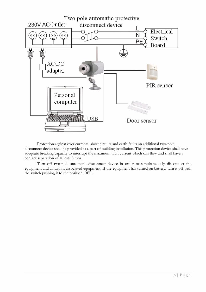
Protection against over currents, short circuits and earth faults an additional two-pole
disconnect device shall be provided as a part of building installation. This protection device shall have adequate breaking capacity to interrupt the maximum fault current which can flow and shall have a contact separation of at least 3 mm.
Turn off two-pole automatic disconnect device in order to simultaneously disconnect the equipment and all with it associated equipment. If the equipment has turned on battery, turn it off with the switch pushing it to the position OFF.
7 | P a g e
2 GETTING STARTED
2.1 Introduction
Teltonika MVC100 EDGE Camera is a compact mobile surveillance and monitoring system for transmission of high resolution video and single images via GPRS/EDGE network. In places with no land line Internet available MVC100 is ideal for remote surveillance and monitoring of temporary or distant sites or mobile assets. The images can be acquired automatically with programmable period and/or upon external triggers such as motion sensors or door contacts. The video and single images can be viewed on a PC or a handheld device, and can also be transmitted to FTP-server and/or by e-mail.
2.2 Package contents
MVC100 EDGE Camera
External GSM antenna
AC/DC Power adapter (Euro or UK plug)
USB cable
Angled wall mount bracket
Leaflet “Quick Start Guide”
CD with software, drivers and manual
Note: The manufacturer does not supply the SIM card, which is mandatory for setting up a connection to the GSM network! The SIM card may be purchased from your GSM (mobile) service provider!
Note: If any of the components is missing or damaged, please contact the retailer or reseller from which this product was purchased.
2.3 Installing the hardware
Before installing the hardware, check package contents to make sure that all items listed above are available.
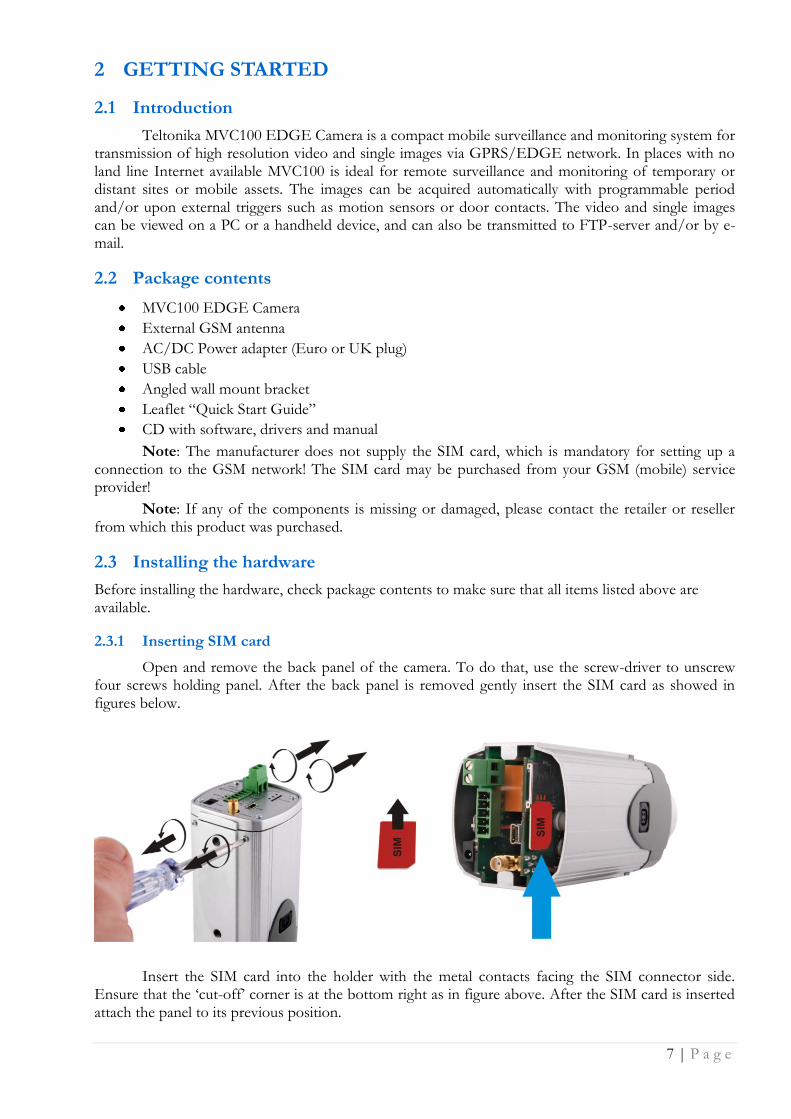
2.3.1 Inserting SIM card
Open and remove the back panel of the camera. To do that, use the screw-driver to unscrew four screws holding panel. After the back panel is removed gently insert the SIM card as showed in figures below.
Insert the SIM card into the holder with the metal contacts facing the SIM connector side. Ensure that the „cut-off‟ corner is at the bottom right as in figure above. After the SIM card is inserted attach the panel to its previous position.
8 | P a g e
2.3.2 Attaching antenna
Screw the antenna in a clockwise direction.
Position the antenna upwards at its connecting joint. This will ensure optimal reception.
2.3.3 Back panel overview
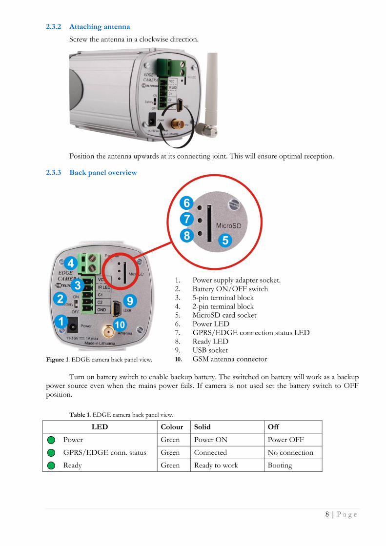
Figure 1. EDGE camera back panel view.
1. Power supply adapter socket. 2. Battery ON/OFF switch 3. 5-pin terminal block 4. 2-pin terminal block 5. MicroSD card socket 6. Power LED 7. GPRS/EDGE connection status LED 8. Ready LED 9. USB socket 10. GSM antenna connector
Turn on battery switch to enable backup battery. The switched on battery will work as a backup power source even when the mains power fails. If camera is not used set the battery switch to OFF position.
Table 1. EDGE camera back panel view.
LED Colour Solid Off
Power Green Power ON Power OFF
GPRS/EDGE conn. status Green Connected No connection
Ready Green Ready to work Booting
9 | P a g e
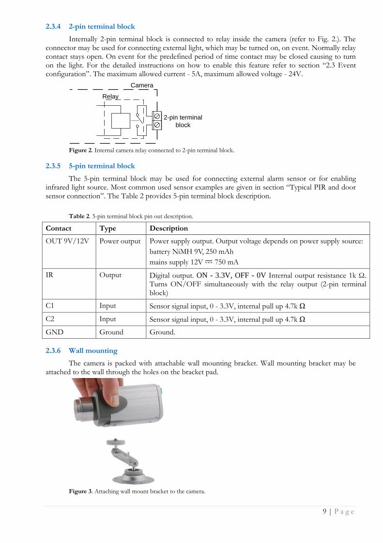
2.3.4 2-pin terminal block
Internally 2-pin terminal block is connected to relay inside the camera (refer to Fig. 2.). The connector may be used for connecting external light, which may be turned on, on event. Normally relay contact stays open. On event for the predefined period of time contact may be closed causing to turn on the light. For the detailed instructions on how to enable this feature refer to section “2.3 Event configuration”. The maximum allowed current - 5A, maximum allowed voltage - 24V.
Relay
Camera
2-pin terminal
block
Figure 2. Internal camera relay connected to 2-pin terminal block.
2.3.5 5-pin terminal block
The 5-pin terminal block may be used for connecting external alarm sensor or for enabling infrared light source. Most common used sensor examples are given in section “Typical PIR and door sensor connection”. The Table 2 provides 5-pin terminal block description.
Table 2. 5-pin terminal block pin out description.
Contact Type Description
OUT 9V/12V Power output Power supply output. Output voltage depends on power supply source:
battery NiMH 9V, 250 mAh
mains supply 12V 750 mA
IR Output Digital output. ON - 3.3V, OFF - 0V Internal output resistance 1k Ω. Turns ON/OFF simultaneously with the relay output (2-pin terminal block)
C1 Input Sensor signal input, 0 - 3.3V, internal pull up 4.7k Ω
C2 Input Sensor signal input, 0 - 3.3V, internal pull up 4.7k Ω
GND Ground Ground.
2.3.6 Wall mounting
The camera is packed with attachable wall mounting bracket. Wall mounting bracket may be attached to the wall through the holes on the bracket pad.
Figure 3. Attaching wall mount bracket to the camera.
10 | P a g e
2.4 Camera access software and drivers
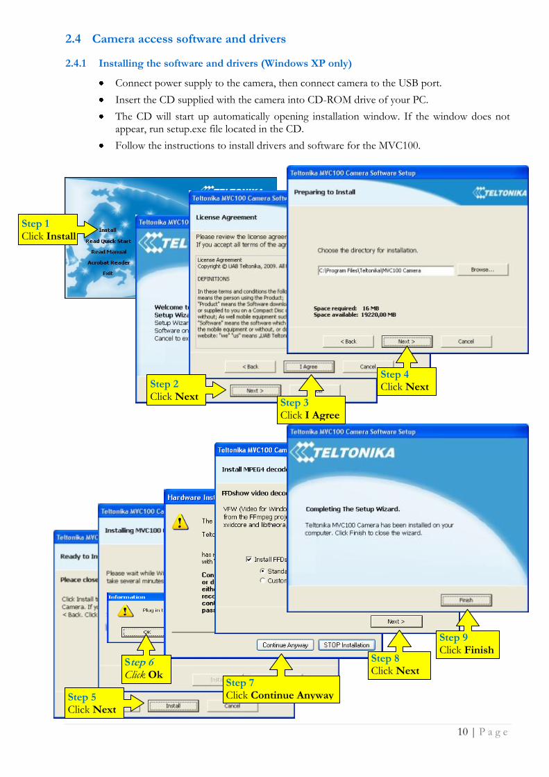
2.4.1 Installing the software and drivers (Windows XP only)
Connect power supply to the camera, then connect camera to the USB port.
Insert the CD supplied with the camera into CD-ROM drive of your PC.
The CD will start up automatically opening installation window. If the window does not appear, run setup.exe file located in the CD.
Follow the instructions to install drivers and software for the MVC100.
Step 1 Click Install
Step 2 Click Next
Step 4 Click Next
Step 5 Click Next
Step 6 Click Ok Step 7
Click Continue Anyway
Step 8 Click Next
Step 9 Click Finish
Step 3 Click I Agree
11 | P a g e
Note: The installation software installs FTDI company USB drivers. If FTDI PC drivers to the PC have never been installed to your PC before, Windows New Hardware Wizard window may appear. Click Cancel to close the window.
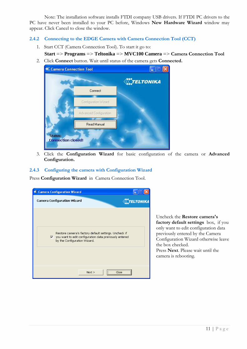
2.4.2 Connecting to the EDGE Camera with Camera Connection Tool (CCT)
1. Start CCT (Camera Connection Tool). To start it go to:
Start => Programs => Teltonika => MVC100 Camera => Camera Connection Tool
2. Click Connect button. Wait until status of the camera gets Connected.
3. Click the Configuration Wizard for basic configuration of the camera or Advanced
Configuration.
2.4.3 Configuring the camera with Configuration Wizard
Press Configuration Wizard in Camera Connection Tool.
Uncheck the Restore camera's factory default settings box, if you only want to edit configuration data previously entered by the Camera Configuration Wizard otherwise leave the box checked. Press Next. Please wait until the camera is rebooting.
12 | P a g e
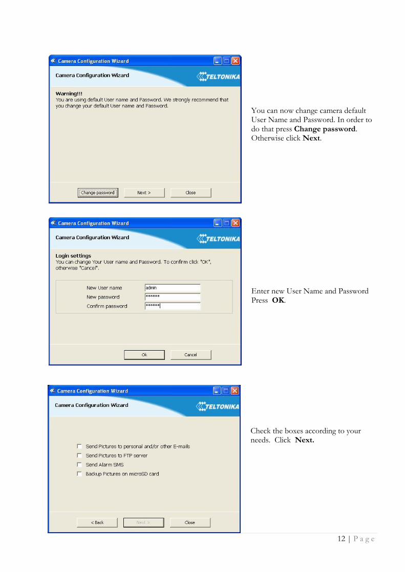
You can now change camera default User Name and Password. In order to do that press Change password. Otherwise click Next.
Enter new User Name and Password Press OK.
Check the boxes according to your needs. Click Next.
13 | P a g e
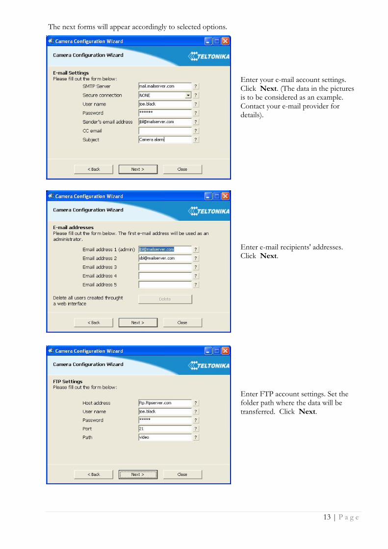
The next forms will appear accordingly to selected options. Enter your e-mail account settings. Click Next. (The data in the pictures is to be considered as an example. Contact your e-mail provider for details).
Enter e-mail recipients' addresses. Click Next.
Enter FTP account settings. Set the folder path where the data will be transferred. Click Next.
14 | P a g e
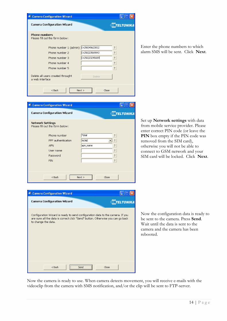
Enter the phone numbers to which alarm SMS will be sent. Click Next.
Set up Network settings with data from mobile service provider. Please enter correct PIN code (or leave the PIN box empty if the PIN code was removed from the SIM card), otherwise you will not be able to connect to GSM network and your SIM card will be locked. Click Next.
Now the configuration data is ready to be sent to the camera. Press Send. Wait until the data is sent to the camera and the camera has been rebooted.
Now the camera is ready to use. When camera detects movement, you will receive e-mails with the videoclip from the camera with SMS notification, and/or the clip will be sent to FTP-server.
15 | P a g e
2.4.4 Advanced Configuration
Click Advanced Configuration button to Start your Internet browser (e.g. IE or Mozilla) with default IP address http://10.0.0.1 (Make sure that cookies are enabled on your browser).
Enter the login information. The default administrator login settings are:
User name: admin
Password: admin
Note: if a Hardware Installation warning appears informing that Teltonika Camera has not passed Windows Logo testing to verify its compatibility with Windows XP, press Continue Anyway.
2.4.5 Notes for using Camera Connection Tool (CCT)
If you are going to unplug the USB cable or power supply from the camera, click “Disconnect” in the CCT window, wait until the message “Disconnected” appears.
If you are going to connect another EDGE camera to the PC close the CCT tool, unplug the camera from the PC, connect the other camera to the PC and make connection using CCT again.
If any problem with the connection occurs close the CCT, unplug the camera from the PC USB port, then connect the camera to the PC and make connection using CCT again. If the problem persists, close CCT, open Start ->Control Panel ->System->Hardware->Device Manager, expand “Modems”, right-click on “Teltonika Camera” and uninstall it. Unplug the power supply and the USB cable from the camera. Then connect the camera to the PC and make connection using CCT again.
2.4.6 Uninstalling the Driver and Software
To uninstall the driver and software follow these instructions:
1. Disconnect the Camera from the PC USB port.
2. Select Start => Programs => Teltonika => MVC100 Camera, click on Uninstall and
then follow the instructions.
Note: alternatively driver and software may be removed from Control Panel:
Start => Settings => Control Panel => Add or Remove Programs. Select Teltonika
MVC100 Camera from the list and then click Remove.
16 | P a g e
2.5 Accessing the Camera
2.5.1 Accessing WEB interface
To access camera‟s WEB interface connect to the camera using CCT tool. After successful connection open the Web browser and type the camera IP address (http://10.0.0.1). If the camera port was changed from default port 80 to another value the IP address must be written in from http://10.0.0.1:1010 (Value 1010 is new port).
If the IP address and port are correct the login page asking for username and password appears:
The default administrator login settings are:
Username: admin Password: admin
2.5.2 WEB configuration page interface structure
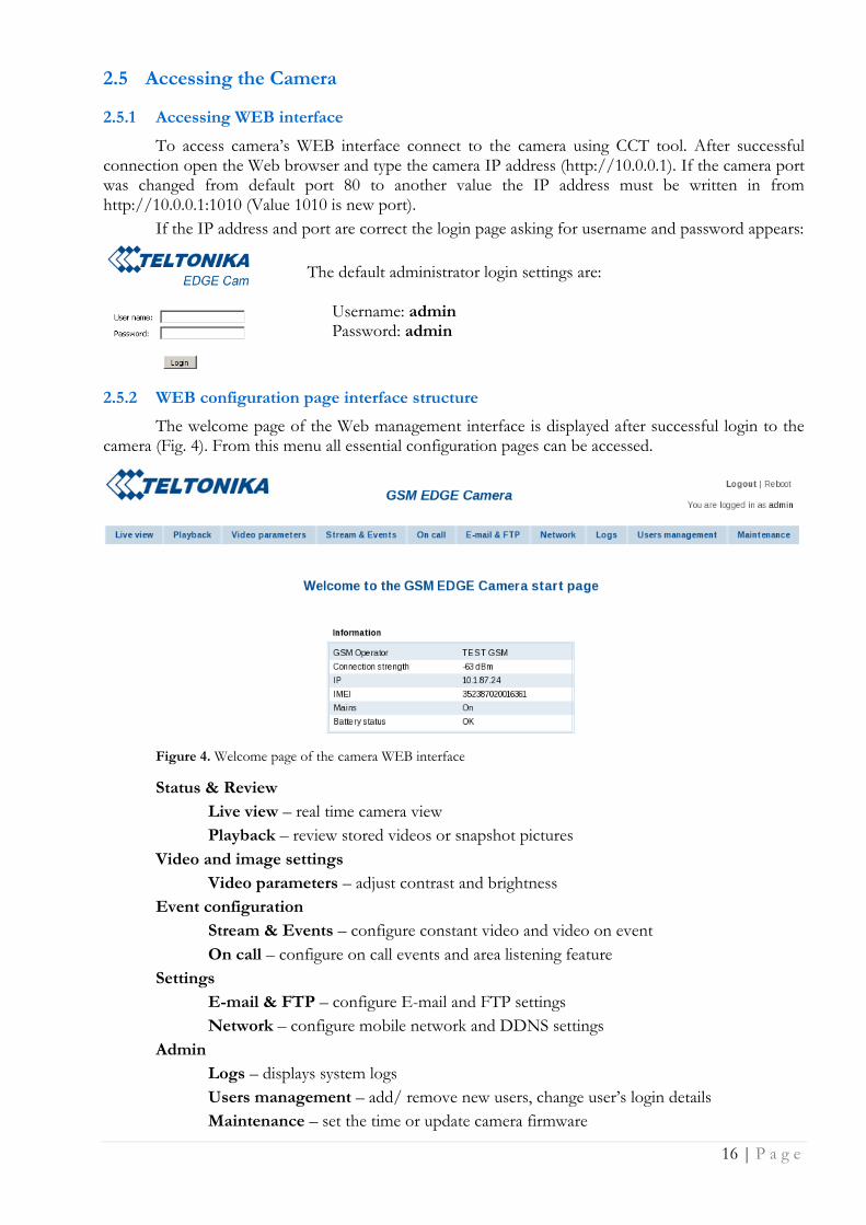
The welcome page of the Web management interface is displayed after successful login to the camera (Fig. 4). From this menu all essential configuration pages can be accessed.
Figure 4. Welcome page of the camera WEB interface
Status & Review
Live view – real time camera view
Playback – review stored videos or snapshot pictures
Video and image settings
Video parameters – adjust contrast and brightness
Event configuration
Stream & Events – configure constant video and video on event
On call – configure on call events and area listening feature
Settings
E-mail & FTP – configure E-mail and FTP settings
Network – configure mobile network and DDNS settings
Admin
Logs – displays system logs
Users management – add/ remove new users, change user‟s login details
Maintenance – set the time or update camera firmware
17 | P a g e
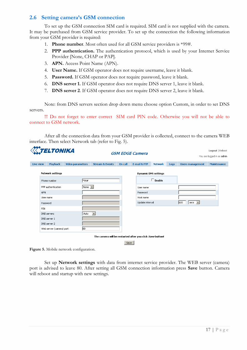
2.6 Setting camera’s GSM connection
To set up the GSM connection SIM card is required. SIM card is not supplied with the camera. It may be purchased from GSM service provider. To set up the connection the following information from your GSM provider is required:
1. Phone number. Most often used for all GSM service providers is *99#.
2. PPP authentication. The authentication protocol, which is used by your Internet Service Provider [None, CHAP or PAP].
3. APN. Access Point Name (APN).
4. User Name. If GSM operator does not require username, leave it blank.
5. Password. If GSM operator does not require password, leave it blank.
6. DNS server 1. If GSM operator does not require DNS server 1, leave it blank.
7. DNS server 2. If GSM operator does not require DNS server 2, leave it blank.
Note: from DNS servers section drop down menu choose option Custom, in order to set DNS servers.
!!! Do not forget to enter correct SIM card PIN code. Otherwise you will not be able to connect to GSM network.
After all the connection data from your GSM provider is collected, connect to the camera WEB interface. Then select Network tab (refer to Fig. 5).
Figure 5. Mobile network configuration.
Set up Network settings with data from internet service provider. The WEB server (camera) port is advised to leave 80. After setting all GSM connection information press Save button. Camera will reboot and startup with new settings.
18 | P a g e
2.7 Accessing Camera from the WEB
There are two ways to connect the EDGE camera from internet: 1. Use SIM card with public static IP address 2. Use SIM card with public dynamic IP address which will be linked to static hostname
using DDNS service.
Note: If the SIM card is with private IP address then reaching camera from the internet is not possible as connection is routed through a NAT firewall in your provider‟s GSM network.
2.7.1 SIM card with public static IP address
Open your WEB browser and type SIM card‟s IP address, when the camera GSM connection has been set up. After successful connection camera‟s login page must appear.
Note: If the Web server (camera) port has been changed in the Network settings then IP address should be written in the following form:
http://A.A.A.A:B,
where A.A.A.A is the camera IP address and B the Camera Web server port.
2.7.2 SIM card with public dynamic IP address
For the SIM card with dynamic public IP address the IP address is given for a limited period of time, which is usually no more than a few hours, then the IP address is changed. As the IP address is continuously changed it becomes a problem to connect to the camera. To solve this problem Dynamic Domain Name Service (DDNS) may be used. DDNS is a domain name service allowing to link dynamic IP addresses to static hostname.
To start using this feature firstly a hostname must be registered on the DDNS server. The camera is preconfigured to connect to the www.dyndns.com server for updating camera IP address. After creating account at www.dyndns.com you will get: Hostname Username and Password.
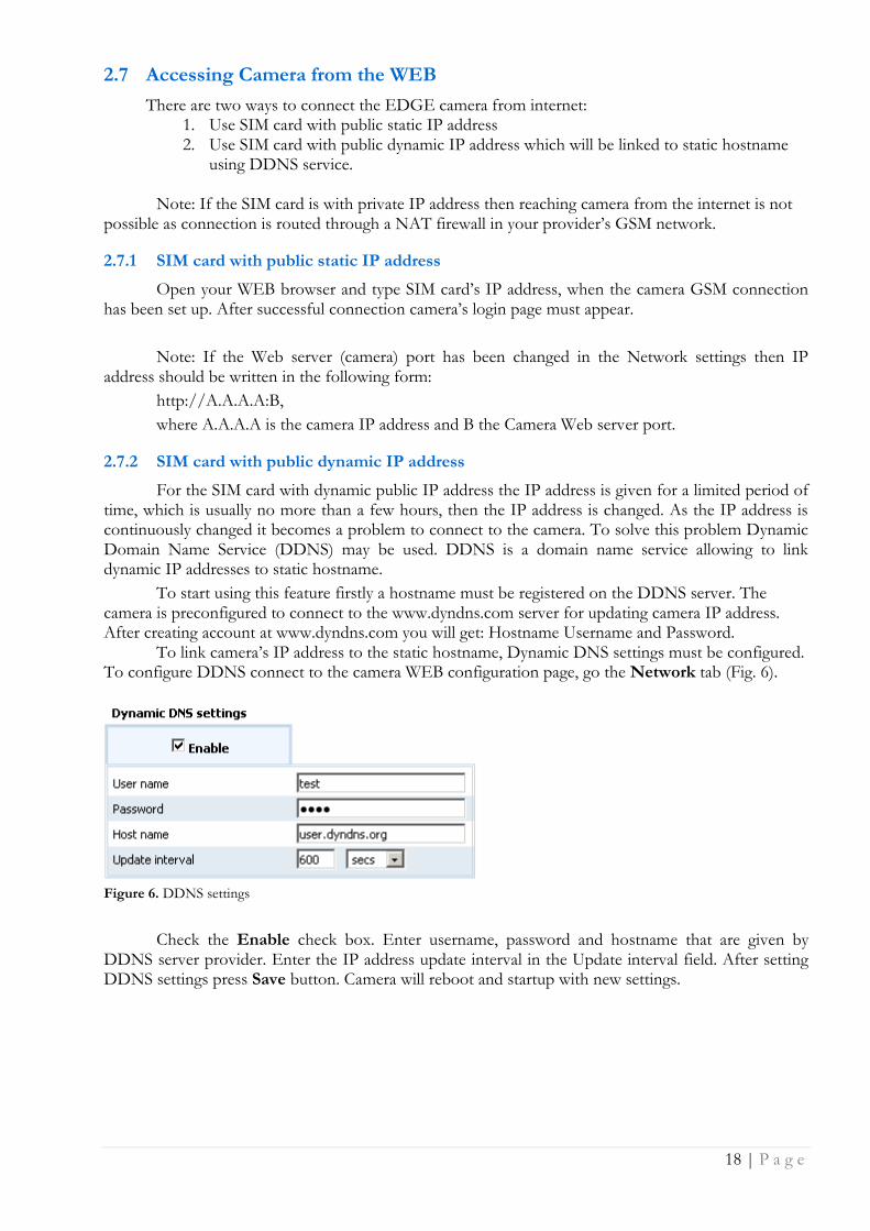
To link camera‟s IP address to the static hostname, Dynamic DNS settings must be configured. To configure DDNS connect to the camera WEB configuration page, go the Network tab (Fig. 6).
Figure 6. DDNS settings
Check the Enable check box. Enter username, password and hostname that are given by DDNS server provider. Enter the IP address update interval in the Update interval field. After setting DDNS settings press Save button. Camera will reboot and startup with new settings.
19 | P a g e
3 EDGE CAMERA CONFIGURATION
3.1 Status & Review
3.1.1 Live view
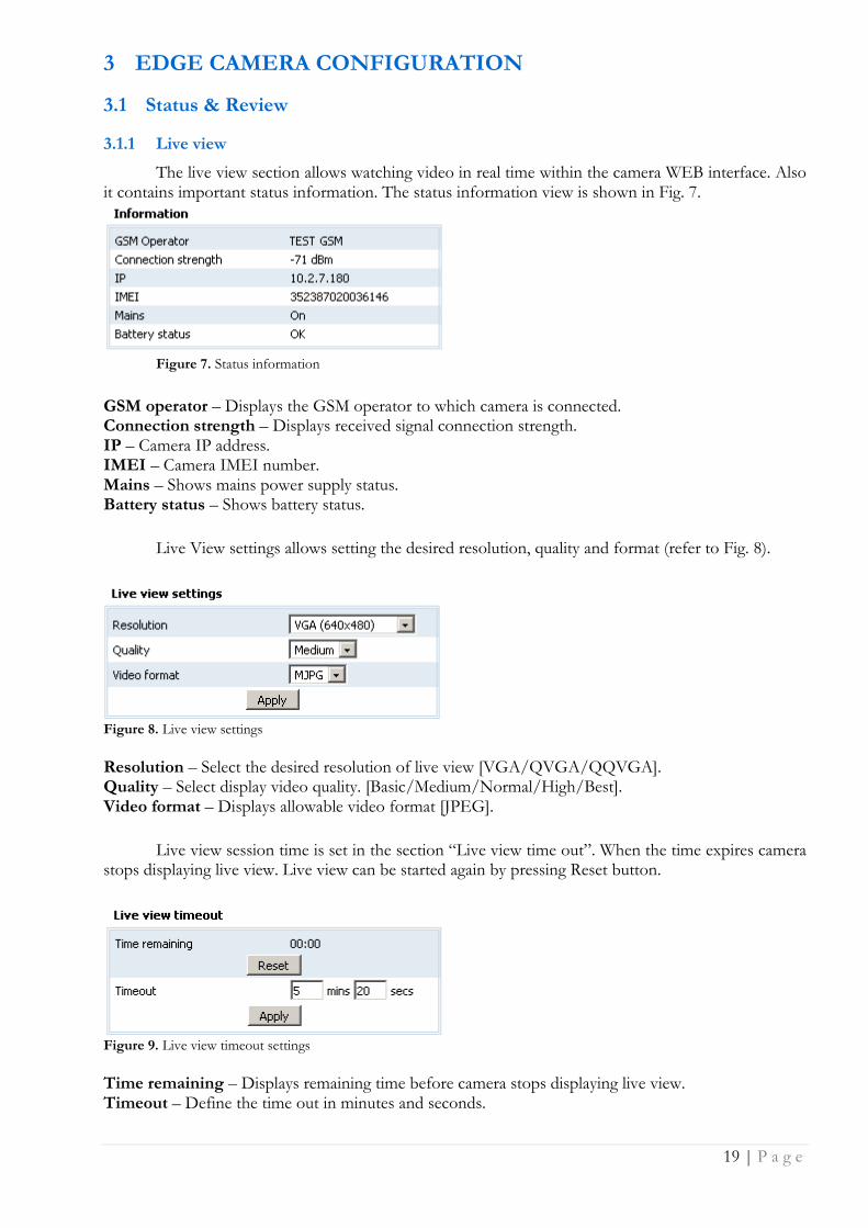
The live view section allows watching video in real time within the camera WEB interface. Also it contains important status information. The status information view is shown in Fig. 7.
Figure 7. Status information
GSM operator – Displays the GSM operator to which camera is connected. Connection strength – Displays received signal connection strength. IP – Camera IP address. IMEI – Camera IMEI number. Mains – Shows mains power supply status. Battery status – Shows battery status.
Live View settings allows setting the desired resolution, quality and format (refer to Fig. 8).
Figure 8. Live view settings Resolution – Select the desired resolution of live view [VGA/QVGA/QQVGA]. Quality – Select display video quality. [Basic/Medium/Normal/High/Best]. Video format – Displays allowable video format [JPEG].
Live view session time is set in the section “Live view time out”. When the time expires camera stops displaying live view. Live view can be started again by pressing Reset button.
Figure 9. Live view timeout settings Time remaining – Displays remaining time before camera stops displaying live view. Timeout – Define the time out in minutes and seconds.
20 | P a g e
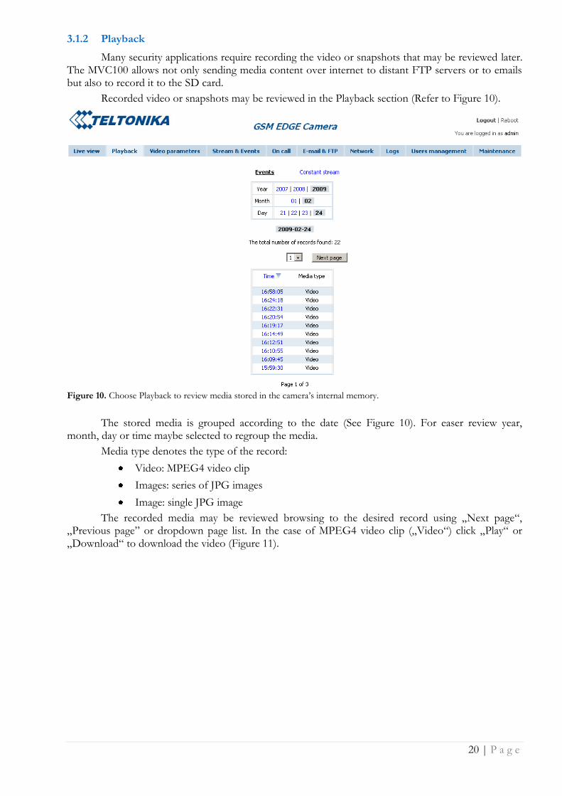
3.1.2 Playback
Many security applications require recording the video or snapshots that may be reviewed later. The MVC100 allows not only sending media content over internet to distant FTP servers or to emails but also to record it to the SD card.
Recorded video or snapshots may be reviewed in the Playback section (Refer to Figure 10).
Figure 10. Choose Playback to review media stored in the camera‟s internal memory.
The stored media is grouped according to the date (See Figure 10). For easer review year, month, day or time maybe selected to regroup the media.
Media type denotes the type of the record:
Video: MPEG4 video clip
Images: series of JPG images
Image: single JPG image
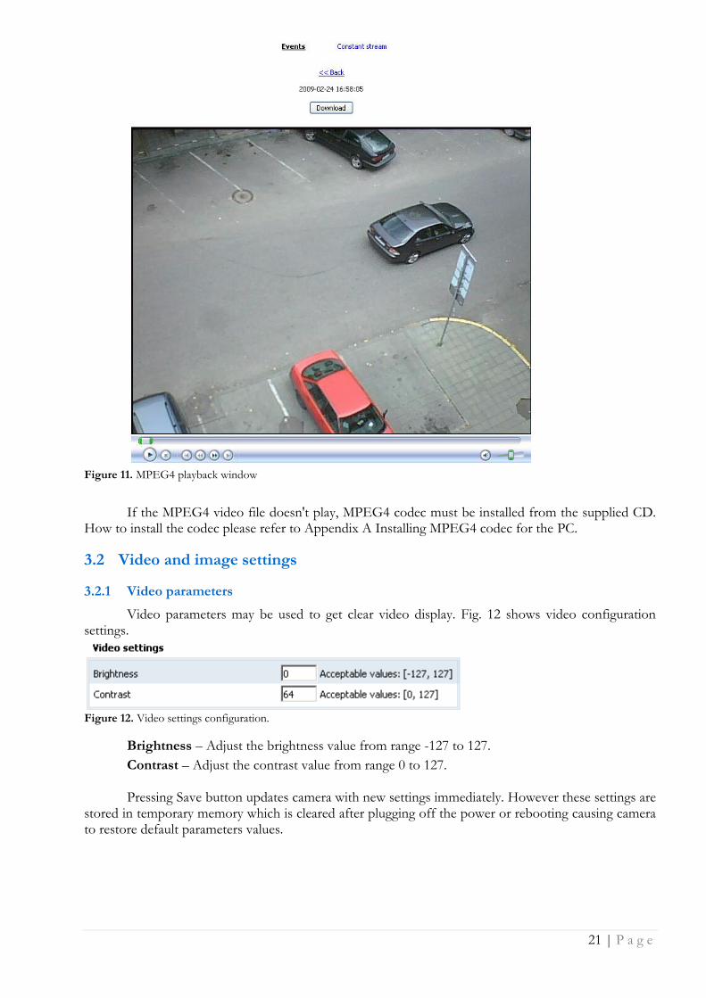
The recorded media may be reviewed browsing to the desired record using „Next page“, „Previous page” or dropdown page list. In the case of MPEG4 video clip („Video“) click „Play“ or „Download“ to download the video (Figure 11).
21 | P a g e
Figure 11. MPEG4 playback window
If the MPEG4 video file doesn't play, MPEG4 codec must be installed from the supplied CD. How to install the codec please refer to Appendix A Installing MPEG4 codec for the PC.
3.2 Video and image settings
3.2.1 Video parameters
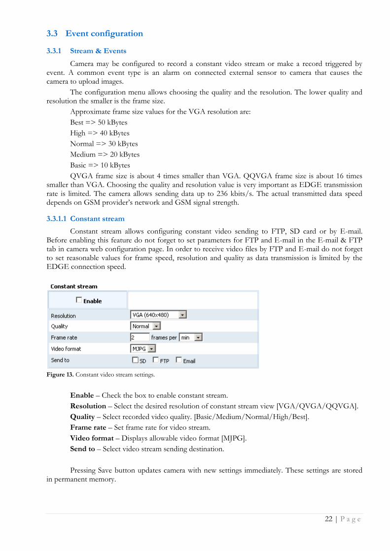
Video parameters may be used to get clear video display. Fig. 12 shows video configuration settings.
Figure 12. Video settings configuration.
Brightness – Adjust the brightness value from range -127 to 127.
Contrast – Adjust the contrast value from range 0 to 127.
Pressing Save button updates camera with new settings immediately. However these settings are stored in temporary memory which is cleared after plugging off the power or rebooting causing camera to restore default parameters values.
22 | P a g e
3.3 Event configuration
3.3.1 Stream & Events
Camera may be configured to record a constant video stream or make a record triggered by event. A common event type is an alarm on connected external sensor to camera that causes the camera to upload images.
The configuration menu allows choosing the quality and the resolution. The lower quality and resolution the smaller is the frame size.
Approximate frame size values for the VGA resolution are:
Best => 50 kBytes
High => 40 kBytes
Normal => 30 kBytes
Medium => 20 kBytes
Basic => 10 kBytes
QVGA frame size is about 4 times smaller than VGA. QQVGA frame size is about 16 times smaller than VGA. Choosing the quality and resolution value is very important as EDGE transmission rate is limited. The camera allows sending data up to 236 kbits/s. The actual transmitted data speed depends on GSM provider‟s network and GSM signal strength.
3.3.1.1 Constant stream
Constant stream allows configuring constant video sending to FTP, SD card or by E-mail. Before enabling this feature do not forget to set parameters for FTP and E-mail in the E-mail & FTP tab in camera web configuration page. In order to receive video files by FTP and E-mail do not forget to set reasonable values for frame speed, resolution and quality as data transmission is limited by the EDGE connection speed.
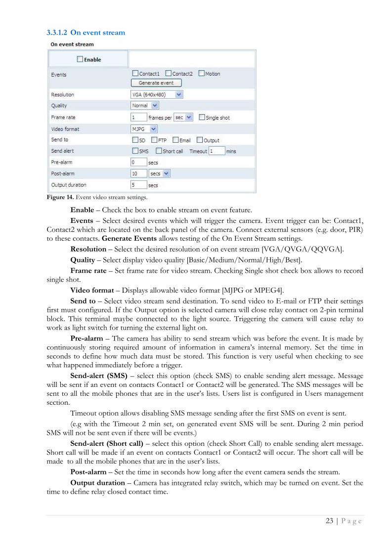
Figure 13. Constant video stream settings.
Enable – Check the box to enable constant stream.
Resolution – Select the desired resolution of constant stream view [VGA/QVGA/QQVGA].
Quality – Select recorded video quality. [Basic/Medium/Normal/High/Best].
Frame rate – Set frame rate for video stream.
Video format – Displays allowable video format [MJPG].
Send to – Select video stream sending destination.
Pressing Save button updates camera with new settings immediately. These settings are stored in permanent memory.
23 | P a g e
3.3.1.2 On event stream
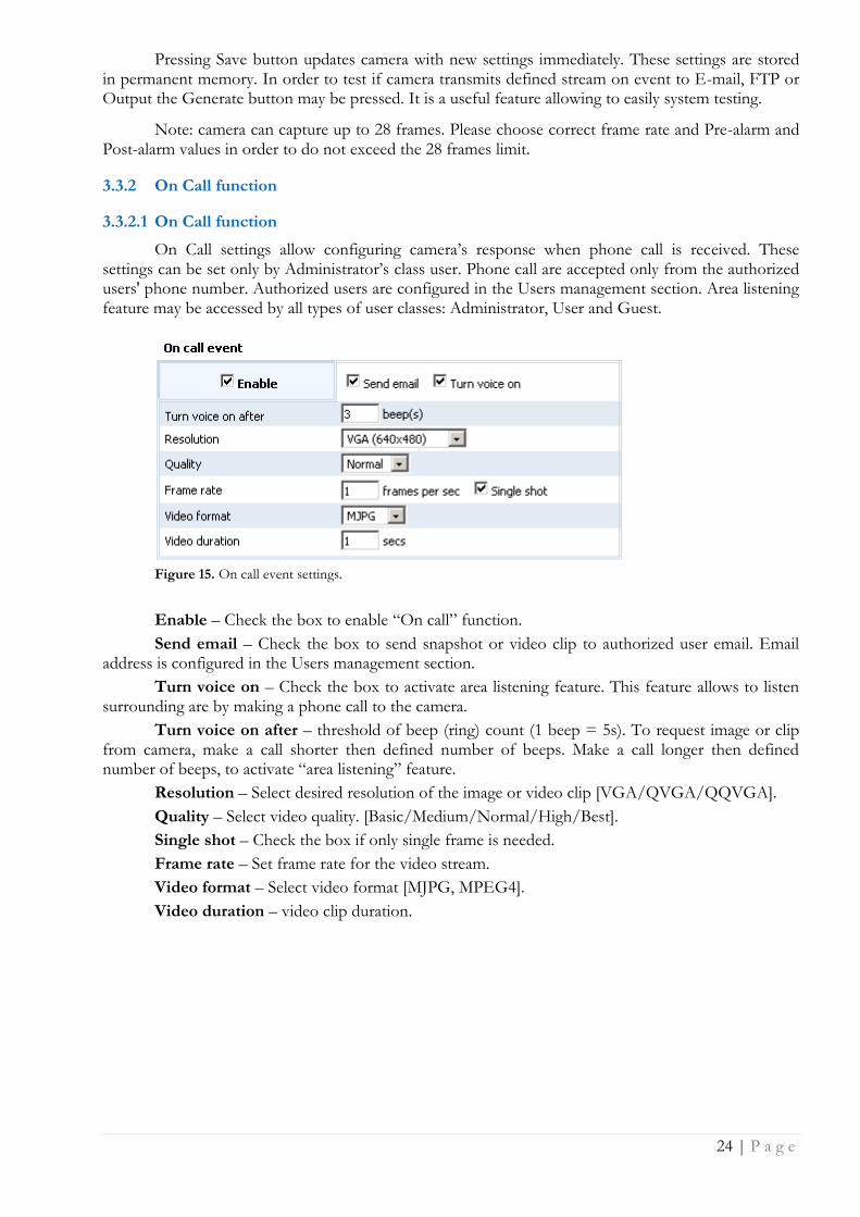
Figure 14. Event video stream settings.
Enable – Check the box to enable stream on event feature.
Events – Select desired events which will trigger the camera. Event trigger can be: Contact1, Contact2 which are located on the back panel of the camera. Connect external sensors (e.g. door, PIR) to these contacts. Generate Events allows testing of the On Event Stream settings.
Resolution – Select the desired resolution of on event stream [VGA/QVGA/QQVGA].
Quality – Select display video quality [Basic/Medium/Normal/High/Best].
Frame rate – Set frame rate for video stream. Checking Single shot check box allows to record single shot.
Video format – Displays allowable video format [MJPG or MPEG4].
Send to – Select video stream send destination. To send video to E-mail or FTP their settings first must configured. If the Output option is selected camera will close relay contact on 2-pin terminal block. This terminal maybe connected to the light source. Triggering the camera will cause relay to work as light switch for turning the external light on.
Pre-alarm – The camera has ability to send stream which was before the event. It is made by continuously storing required amount of information in camera‟s internal memory. Set the time in seconds to define how much data must be stored. This function is very useful when checking to see what happened immediately before a trigger.
Send-alert (SMS) – select this option (check SMS) to enable sending alert message. Message will be sent if an event on contacts Contact1 or Contact2 will be generated. The SMS messages will be sent to all the mobile phones that are in the user‟s lists. Users list is configured in Users management section.
Timeout option allows disabling SMS message sending after the first SMS on event is sent.
(e.g with the Timeout 2 min set, on generated event SMS will be sent. During 2 min period SMS will not be sent even if there will be events.)
Send-alert (Short call) – select this option (check Short Call) to enable sending alert message. Short call will be made if an event on contacts Contact1 or Contact2 will occur. The short call will be made to all the mobile phones that are in the user‟s lists.
Post-alarm – Set the time in seconds how long after the event camera sends the stream.
Output duration – Camera has integrated relay switch, which may be turned on event. Set the time to define relay closed contact time.
24 | P a g e
Pressing Save button updates camera with new settings immediately. These settings are stored in permanent memory. In order to test if camera transmits defined stream on event to E-mail, FTP or Output the Generate button may be pressed. It is a useful feature allowing to easily system testing.
Note: camera can capture up to 28 frames. Please choose correct frame rate and Pre-alarm and Post-alarm values in order to do not exceed the 28 frames limit.
3.3.2 On Call function
3.3.2.1 On Call function
On Call settings allow configuring camera‟s response when phone call is received. These settings can be set only by Administrator‟s class user. Phone call are accepted only from the authorized users' phone number. Authorized users are configured in the Users management section. Area listening feature may be accessed by all types of user classes: Administrator, User and Guest.
Figure 15. On call event settings.
Enable – Check the box to enable “On call” function.
Send email – Check the box to send snapshot or video clip to authorized user email. Email address is configured in the Users management section.
Turn voice on – Check the box to activate area listening feature. This feature allows to listen surrounding are by making a phone call to the camera.
Turn voice on after – threshold of beep (ring) count (1 beep = 5s). To request image or clip from camera, make a call shorter then defined number of beeps. Make a call longer then defined number of beeps, to activate “area listening” feature.
Resolution – Select desired resolution of the image or video clip [VGA/QVGA/QQVGA].
Quality – Select video quality. [Basic/Medium/Normal/High/Best].
Single shot – Check the box if only single frame is needed.
Frame rate – Set frame rate for the video stream.
Video format – Select video format [MJPG, MPEG4].
Video duration – video clip duration.
25 | P a g e
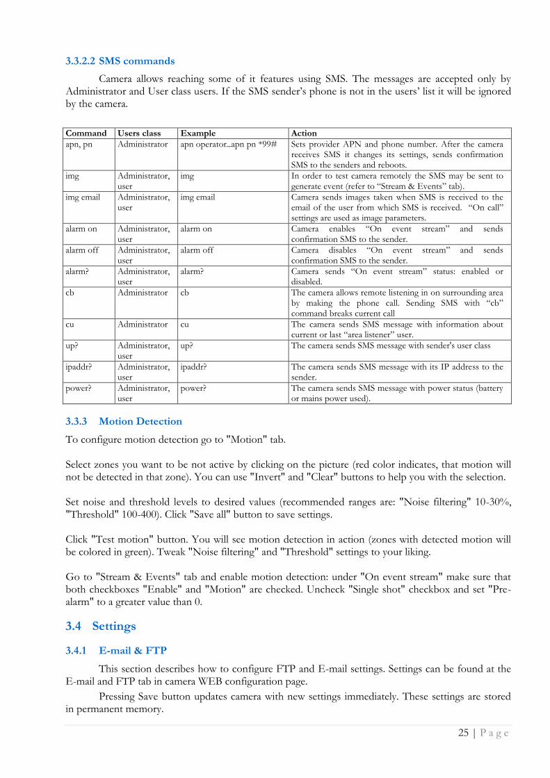
3.3.2.2 SMS commands
Camera allows reaching some of it features using SMS. The messages are accepted only by Administrator and User class users. If the SMS sender‟s phone is not in the users‟ list it will be ignored by the camera.
Command Users class Example Action
apn, pn Administrator apn operator_apn pn *99# Sets provider APN and phone number. After the camera receives SMS it changes its settings, sends confirmation SMS to the senders and reboots.
img Administrator, user
img In order to test camera remotely the SMS may be sent to generate event (refer to “Stream & Events” tab).
img email Administrator, user
img email Camera sends images taken when SMS is received to the email of the user from which SMS is received. “On call” settings are used as image parameters.
alarm on Administrator, user
alarm on Camera enables “On event stream” and sends confirmation SMS to the sender.
alarm off Administrator, user
alarm off Camera disables “On event stream” and sends confirmation SMS to the sender.
alarm? Administrator, user
alarm? Camera sends “On event stream” status: enabled or disabled.
cb Administrator cb The camera allows remote listening in on surrounding area by making the phone call. Sending SMS with “cb” command breaks current call
cu Administrator cu The camera sends SMS message with information about current or last “area listener” user.
up? Administrator, user
up? The camera sends SMS message with sender's user class
ipaddr? Administrator, user
ipaddr? The camera sends SMS message with its IP address to the sender.
power? Administrator, user
power? The camera sends SMS message with power status (battery or mains power used).
3.3.3 Motion Detection
To configure motion detection go to "Motion" tab. Select zones you want to be not active by clicking on the picture (red color indicates, that motion will not be detected in that zone). You can use "Invert" and "Clear" buttons to help you with the selection. Set noise and threshold levels to desired values (recommended ranges are: "Noise filtering" 10-30%, "Threshold" 100-400). Click "Save all" button to save settings. Click "Test motion" button. You will see motion detection in action (zones with detected motion will be colored in green). Tweak "Noise filtering" and "Threshold" settings to your liking. Go to "Stream & Events" tab and enable motion detection: under "On event stream" make sure that both checkboxes "Enable" and "Motion" are checked. Uncheck "Single shot" checkbox and set "Pre-alarm" to a greater value than 0.
3.4 Settings
3.4.1 E-mail & FTP
This section describes how to configure FTP and E-mail settings. Settings can be found at the E-mail and FTP tab in camera WEB configuration page.
Pressing Save button updates camera with new settings immediately. These settings are stored in permanent memory.
26 | P a g e
3.4.1.1 E-mail
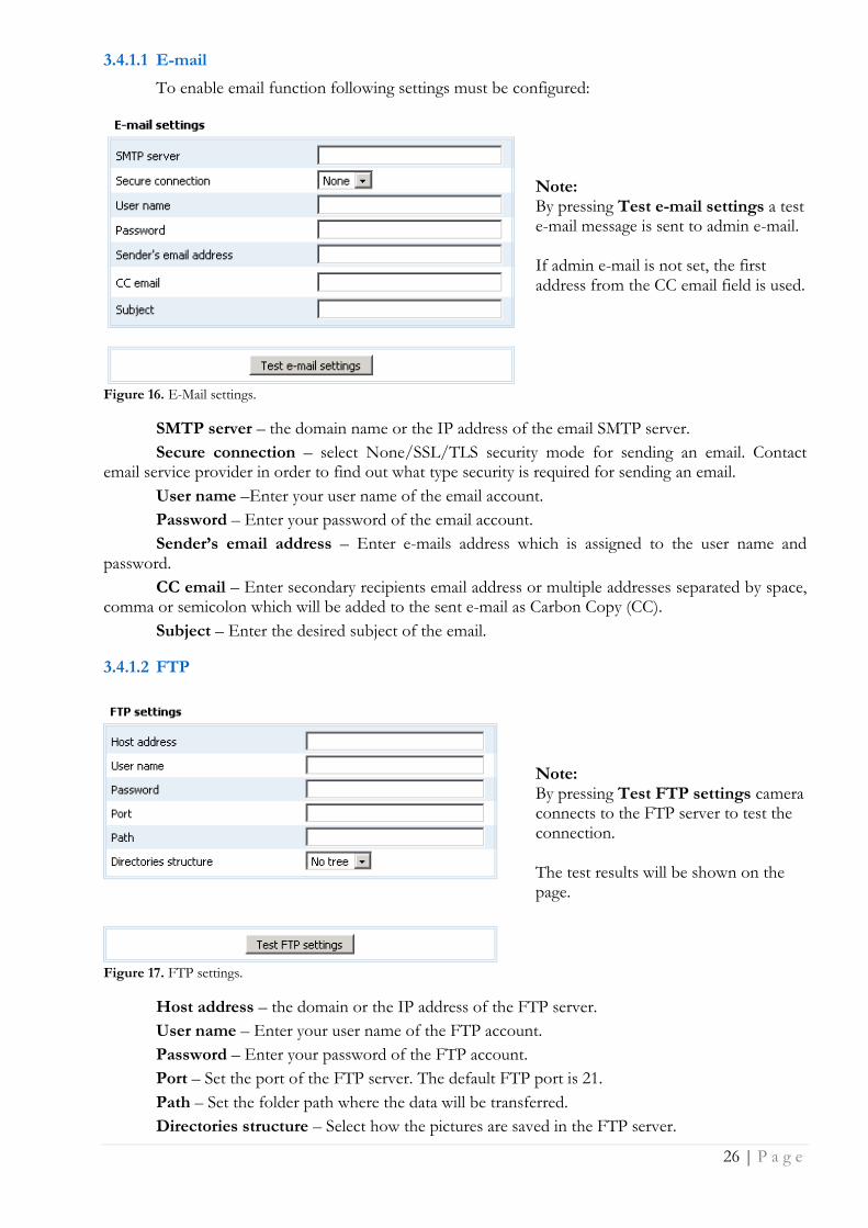
To enable email function following settings must be configured:
Note: By pressing Test e-mail settings a test e-mail message is sent to admin e-mail. If admin e-mail is not set, the first address from the CC email field is used.
Figure 16. E-Mail settings.
SMTP server – the domain name or the IP address of the email SMTP server.
Secure connection – select None/SSL/TLS security mode for sending an email. Contact email service provider in order to find out what type security is required for sending an email.
User name –Enter your user name of the email account.
Password – Enter your password of the email account.
Sender’s email address – Enter e-mails address which is assigned to the user name and password.
CC email – Enter secondary recipients email address or multiple addresses separated by space, comma or semicolon which will be added to the sent e-mail as Carbon Copy (CC).
Subject – Enter the desired subject of the email.
3.4.1.2 FTP
Note: By pressing Test FTP settings camera connects to the FTP server to test the connection. The test results will be shown on the page.
Figure 17. FTP settings.
Host address – the domain or the IP address of the FTP server.
User name – Enter your user name of the FTP account.
Password – Enter your password of the FTP account.
Port – Set the port of the FTP server. The default FTP port is 21.
Path – Set the folder path where the data will be transferred.
Directories structure – Select how the pictures are saved in the FTP server.
27 | P a g e
Full – camera will create directories structure (year => month => day) in the defined FTP path. This function is useful if there is a need for sorting pictures according to the date.
No tree - all files are stored to defined FTP directory.
One file – the camera will rewrite the older picture with the newer, so that only the last picture will be available for review in the FTP server.
3.4.2 Network
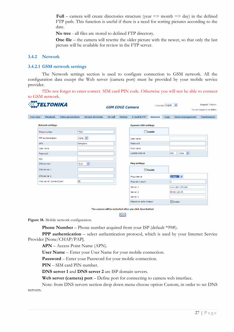
3.4.2.1 GSM network settings
The Network settings section is used to configure connection to GSM network. All the configuration data except the Web server (camera port) must be provided by your mobile service provider.
!!!Do not forget to enter correct SIM card PIN code. Otherwise you will not be able to connect to GSM network.
Figure 18. Mobile network configuration.
Phone Number – Phone number acquired from your ISP (default *99#).
PPP authentication – select authentication protocol, which is used by your Internet Service Provider [None/CHAP/PAP].
APN – Access Point Name (APN).
User Name – Enter your User Name for your mobile connection.
Password – Enter your Password for your mobile connection.
PIN – SIM card PIN number.
DNS server 1 and DNS server 2 are ISP domain servers.
Web server (camera) port – Define port for connecting to camera web interface.
Note: from DNS servers section drop down menu choose option Custom, in order to set DNS servers.

28 | P a g e
Set up Network settings with data from internet service provider. The Web server (camera) port is advised to leave 80. After setting all GSM connection information press Save button. Camera will reboot and startup with new settings.
29 | P a g e
3.4.2.2 Dynamic DNS Settings
Dynamic DNS (DDNS) is a domain name service allowing to link dynamic IP addresses to static hostname. In order to have functional DDNS feature the SIM card with public static or dynamic address must be purchased from the GSM Internet service provider.
To start using this feature firstly a hostname must be registered on the DDNS server. The camera is preconfigured to connect to the www.dyndns.com server for updating camera‟s IP address. After creating account at www.dyndns.com you will get: Hostname User name and Password.
To link camera‟s IP address to the static hostname, Dynamic DNS settings must be configured. To configure DDNS connect to the camera WEB configuration page and go to Network tab (Fig. 19).
Figure 19. Dynamic DNS Settings.
Enable – check the box to enable DDNS.
User name - enter your user name. The camera will use it to automatically login to update your IP address in the DDNS server.
Password – enter you login password.
Hostname - enter your hostname which was registered in DDSN server.
Update interval – enter IP address update time in selected time periods.
After filling DDNS settings fields press Save button. Camera will reboot and startup with new settings.
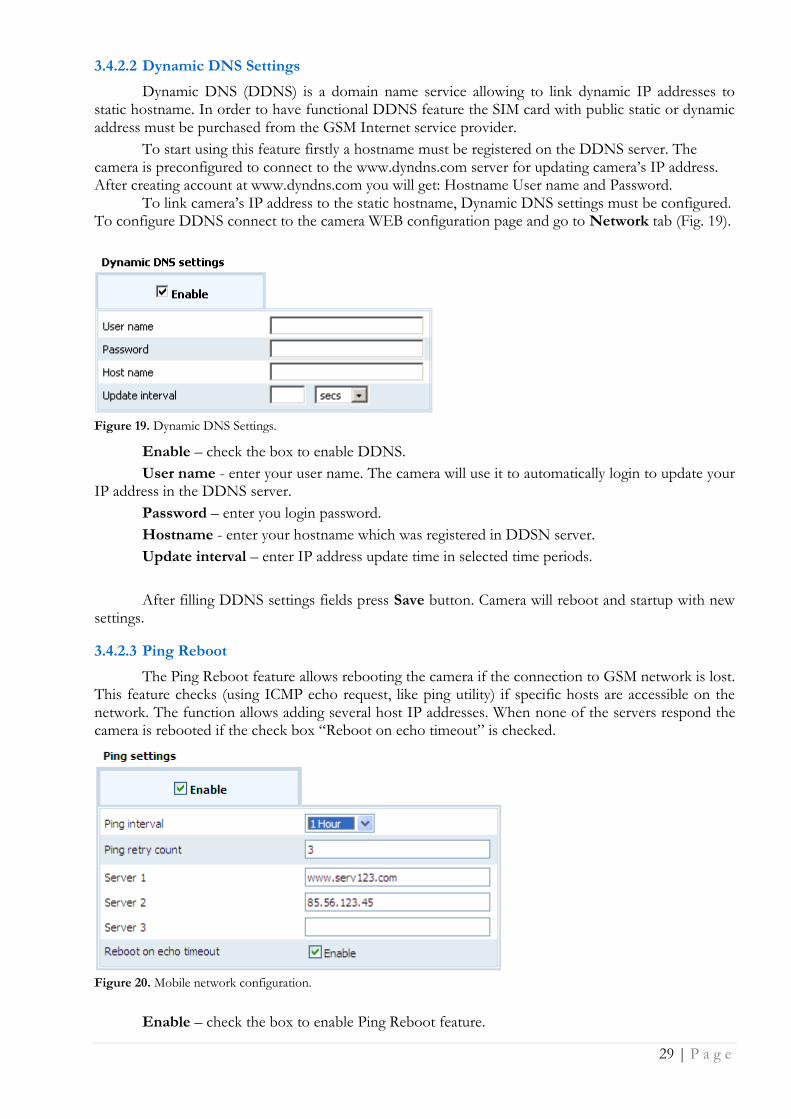
3.4.2.3 Ping Reboot
The Ping Reboot feature allows rebooting the camera if the connection to GSM network is lost. This feature checks (using ICMP echo request, like ping utility) if specific hosts are accessible on the network. The function allows adding several host IP addresses. When none of the servers respond the camera is rebooted if the check box “Reboot on echo timeout” is checked.
Figure 20. Mobile network configuration.
Enable – check the box to enable Ping Reboot feature.

30 | P a g e
Ping interval – specify the monitoring time period in seconds
Ping retry count – specify the number of failed reach ability checks
Reboot on echo timeout – enable reboot the camera if no echo to sent ICMP requests is received.
Server 1, Server 2, Server 3 – Set the host IP address to which ICMP requests will be sent.
31 | P a g e
3.5 Admin
3.5.1 Logs
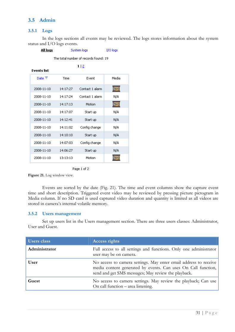
In the logs sections all events may be reviewed. The logs stores information about the system status and I/O logs events.
Figure 21. Log window view.
Events are sorted by the date (Fig. 21). The time and event columns show the capture event time and short description. Triggered event video may be reviewed by pressing picture pictogram in Media column. If no SD card is used captured video duration and quantity is limited as all videos are stored in camera‟s internal volatile memory.
3.5.2 Users management
Set up users list in the Users management section. There are three users classes: Administrator, User and Guest.
Users class Access rights
Administrator Full access to all settings and functions. Only one administrator user may be on camera.
User No access to camera settings. May enter email address to receive media content generated by events. Can uses On Call function, send and get SMS messages; May review the playback.
Guest No access to camera settings. May review the playback; Can use On call function – area listening.
32 | P a g e
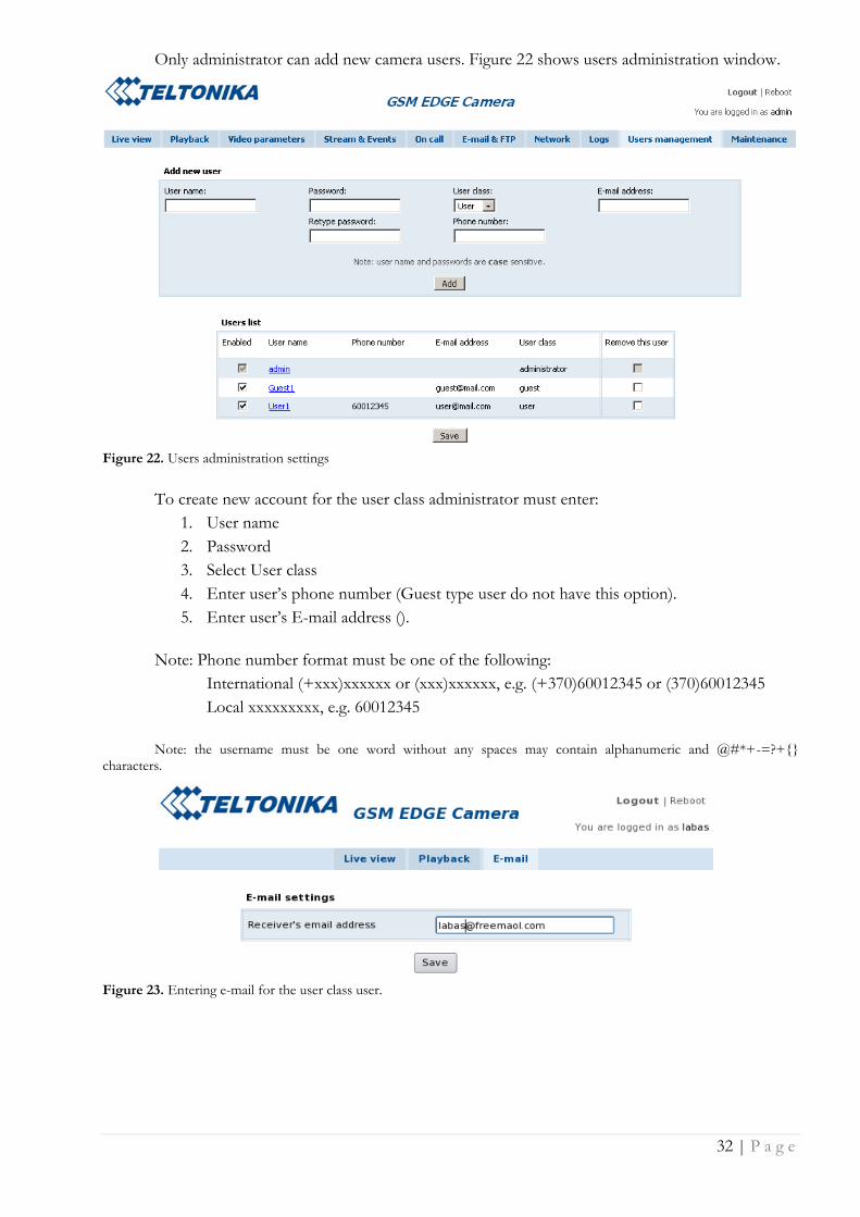
Only administrator can add new camera users. Figure 22 shows users administration window.
Figure 22. Users administration settings
To create new account for the user class administrator must enter:
1. User name
2. Password
3. Select User class
4. Enter user‟s phone number (Guest type user do not have this option).
5. Enter user‟s E-mail address ().
Note: Phone number format must be one of the following:
International (+xxx)xxxxxx or (xxx)xxxxxx, e.g. (+370)60012345 or (370)60012345
Local xxxxxxxxx, e.g. 60012345
Note: the username must be one word without any spaces may contain alphanumeric and @#*+-=?+{} characters.
Figure 23. Entering e-mail for the user class user.
33 | P a g e
To change the administrator login name and password click on the user admin as shown in Figure 24.
Figure 24. Selecting account to make changes.
After the selecting admin user the new window will appear for editing user‟s data (Figure 25).
Figure 25. Editing user‟s data.
The Guest and User accounts may be edited in the same manner as the administrator. By selecting wanted user the new window will appear allowing to change user‟s data. The administrator can edit, add or remove users, change their login, e-mail or phone number.
3.5.3 Maintenance
3.5.3.1 Set the time
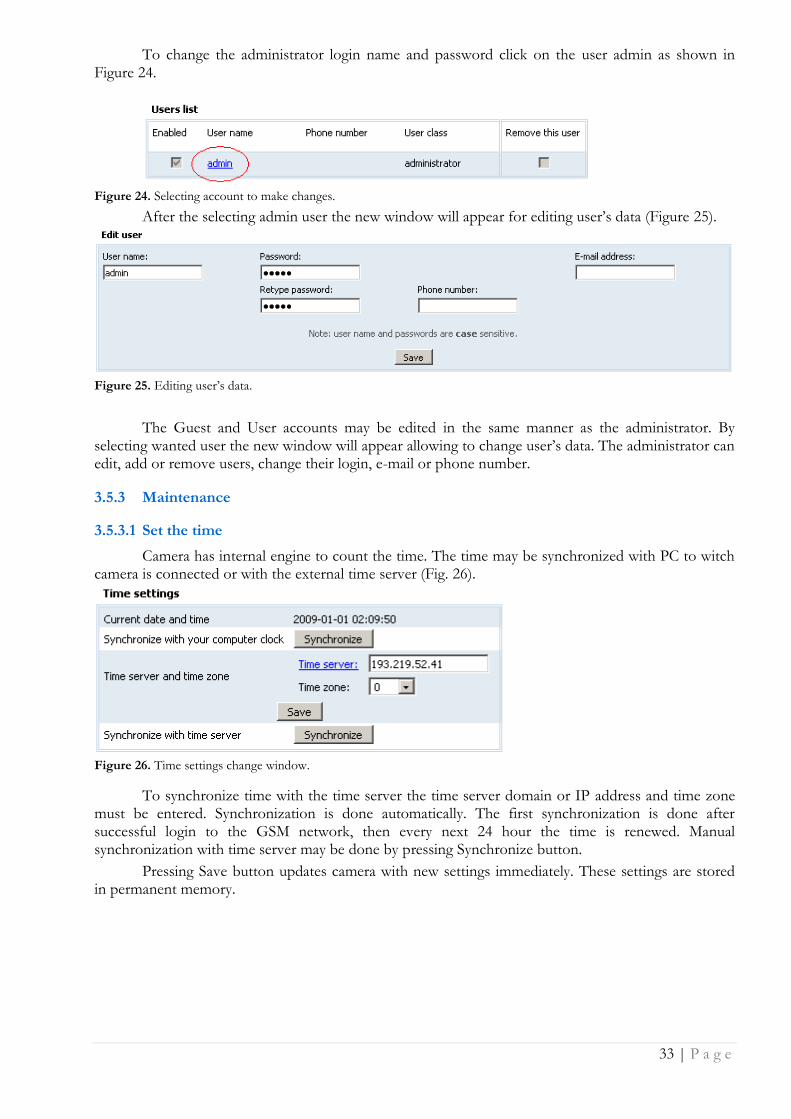
Camera has internal engine to count the time. The time may be synchronized with PC to witch camera is connected or with the external time server (Fig. 26).
Figure 26. Time settings change window.
To synchronize time with the time server the time server domain or IP address and time zone must be entered. Synchronization is done automatically. The first synchronization is done after successful login to the GSM network, then every next 24 hour the time is renewed. Manual synchronization with time server may be done by pressing Synchronize button.
Pressing Save button updates camera with new settings immediately. These settings are stored in permanent memory.
34 | P a g e
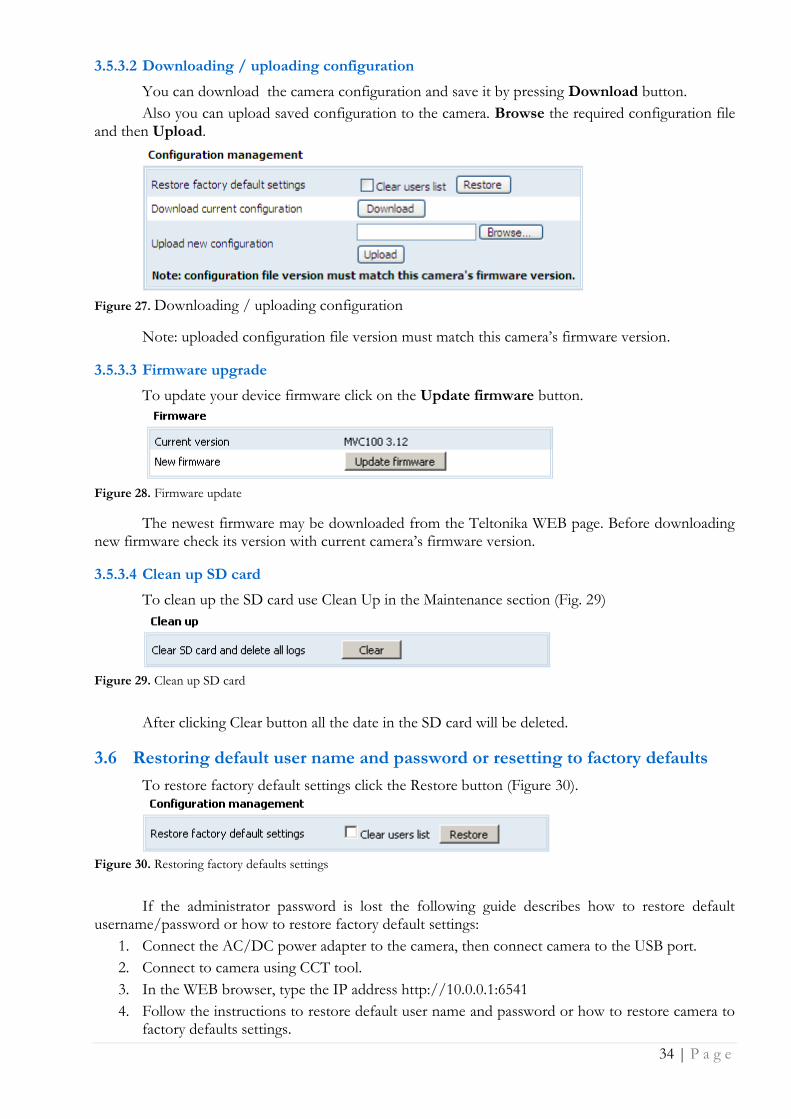
3.5.3.2 Downloading / uploading configuration
You can download the camera configuration and save it by pressing Download button.
Also you can upload saved configuration to the camera. Browse the required configuration file and then Upload.
Figure 27. Downloading / uploading configuration
Note: uploaded configuration file version must match this camera‟s firmware version.
3.5.3.3 Firmware upgrade
To update your device firmware click on the Update firmware button.
Figure 28. Firmware update
The newest firmware may be downloaded from the Teltonika WEB page. Before downloading new firmware check its version with current camera‟s firmware version.
3.5.3.4 Clean up SD card
To clean up the SD card use Clean Up in the Maintenance section (Fig. 29)
Figure 29. Clean up SD card
After clicking Clear button all the date in the SD card will be deleted.
3.6 Restoring default user name and password or resetting to factory defaults
To restore factory default settings click the Restore button (Figure 30).
Figure 30. Restoring factory defaults settings
If the administrator password is lost the following guide describes how to restore default username/password or how to restore factory default settings:
1. Connect the AC/DC power adapter to the camera, then connect camera to the USB port.
2. Connect to camera using CCT tool.
3. In the WEB browser, type the IP address http://10.0.0.1:6541
4. Follow the instructions to restore default user name and password or how to restore camera to factory defaults settings.
35 | P a g e
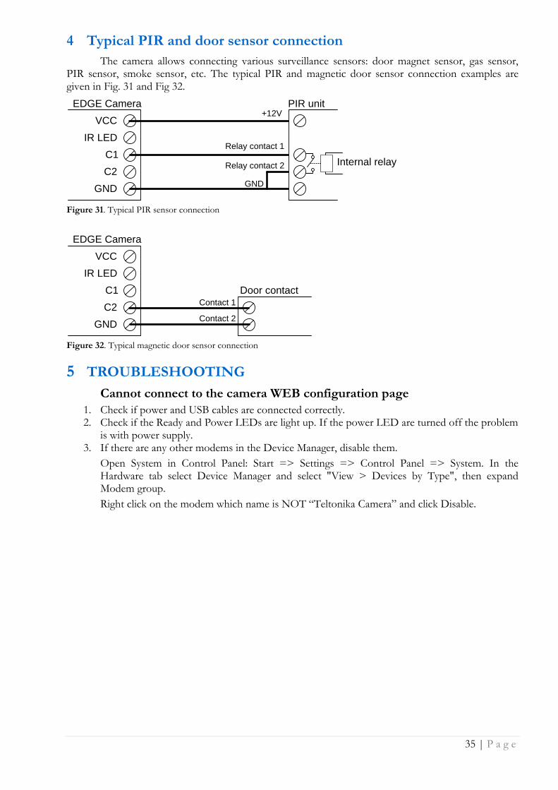
4 Typical PIR and door sensor connection
The camera allows connecting various surveillance sensors: door magnet sensor, gas sensor, PIR sensor, smoke sensor, etc. The typical PIR and magnetic door sensor connection examples are given in Fig. 31 and Fig 32.
EDGE Camera
VCC
IR LED
C1
C2
GND
+12V
Relay contact 1
GND
PIR unit
Relay contact 2
Internal relay
Figure 31. Typical PIR sensor connection
Contact 1
Door contact
Contact 2
EDGE Camera
VCC
IR LED
C1
C2
GND
Figure 32. Typical magnetic door sensor connection
5 TROUBLESHOOTING
Cannot connect to the camera WEB configuration page
1. Check if power and USB cables are connected correctly. 2. Check if the Ready and Power LEDs are light up. If the power LED are turned off the problem
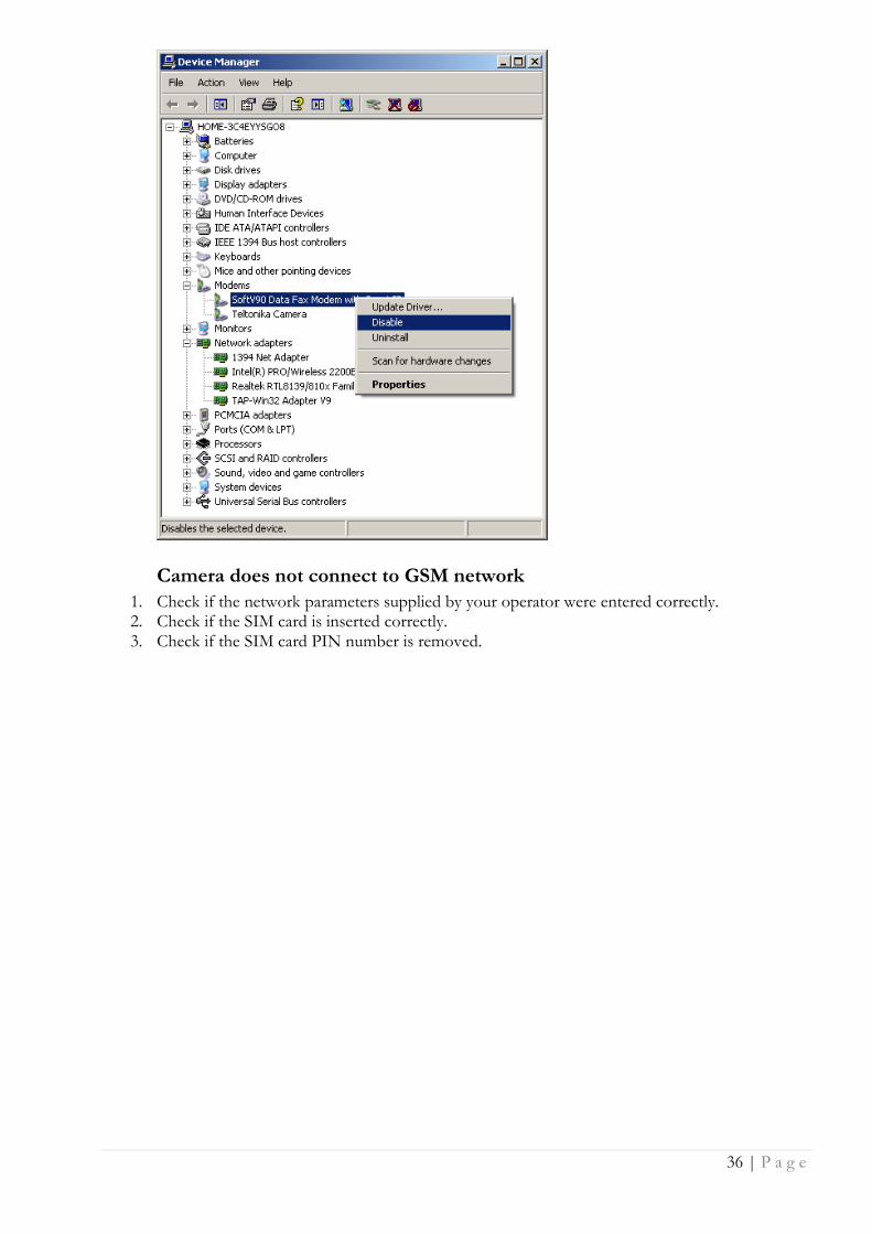
is with power supply. 3. If there are any other modems in the Device Manager, disable them.
Open System in Control Panel: Start => Settings => Control Panel => System. In the Hardware tab select Device Manager and select "View > Devices by Type", then expand Modem group.
Right click on the modem which name is NOT “Teltonika Camera” and click Disable.
36 | P a g e
Camera does not connect to GSM network
1. Check if the network parameters supplied by your operator were entered correctly. 2. Check if the SIM card is inserted correctly. 3. Check if the SIM card PIN number is removed.
37 | P a g e
6 TECHNICAL SPECIFICATION
Management
User-friendly Web GUI
IMAGE
Image sensor: VGA (640x480 pixels). Image resolution: VGA/QVGA/QQVGA Image compression: JPEG Video clip (programmable time duration) and/or single snapshot SECURITY Security for administration/configuration: only authorized users are allowed (user name and password) CONFIGURATION & CONTROL Built-in web server for easy configuration and firmware update Built-in web server may be accessed: Remotely over GSM network Locally via USB connection
IMAGE TRANSMISSION Image transmission over GPRS/EDGE network to:
FTP-server E-mail
TRANSMISSION CONTROL Transmitting and/or saving images on sensor activity (for example: PIR sensor, door contact...) Pre-alarm function (ability to record video before sensor activity) Possibility to stop transfer/record activity on external contact
EDGE 850/900/1800/1900 MHz
GSM Power Class 4 (2W) for 850/900 bands.
GSM Power Class 1 (1W) for 1800/1900 bands.
EDGE class E2 (+27 dBm in 850/900 bands, +26 dBm in 1800/1900 bands).
GPRS/EGPRS Multi slot Class 12 (4 slots Rx, 4 slots Tx).
GPRS/EGPRS Class B Type 1 MT.
GPRS CS1-CS4; EGPRS MCS1-MCS9.
TEMPERATURES & HUMIDITY Operating temperature 0ºC to 50ºC. Relative humidity: maximal 80% Store and transport conditions:
Temperature: -20˚ to 60˚ C. Relative humidity 5% to 95%
Note: Before using the equipment do not unpack it until package temperature reaches operating temperature. It is required if the device was stored in the temperature that exceeds operating temperature range.

38 | P a g e
OTHER Lighting control: relay contacts Backup battery Power source detection:
Mains indication Low battery power detection
GSM operator's identification GSM signal level measurement and display microSD CARD
Maximum card capacity 8GByte
Recommended microSDHC cards:
A-Data 4 GByte microSDHC card
A-Data 8 GByte microSDHC card
Transcend 4 GByte microSDHC card
Transcend 8 GByte microSDHC card
POWER SUPPLY
Mains adapter: 12V DC 1A Internal backup battery NiMH 9V, 250 mAh. Battery charging time 9h.
ELECTRICAL CHARACTERISTICS
Nominal power supply voltage 12V
Current consumption when idle 100 mA
Current consumption when operating 250 mA

39 | P a g e
7 ORDERING INFORMATION
Part number Router model
MVC100 EH1100 Quad Band GPRS/EDGE camera, Euro PSU
MVC100 BH1100 Quad Band GPRS/EDGE camera, UK PSU
MVC100 EH2100 Quad Band GPRS/EDGE camera, Euro PSU, packing box without brand
MVC100 BH2100 Quad Band GPRS/EDGE camera, UK PSU, packing box without brand
MVC100 EH2300 Quad Band GPRS/EDGE camera, Euro PSU, PIR sensor, 5m cable
MVC100BH2300 Quad Band GPRS/EDGE camera, UK PSU, PIR sensor, 5m cable
40 | P a g e
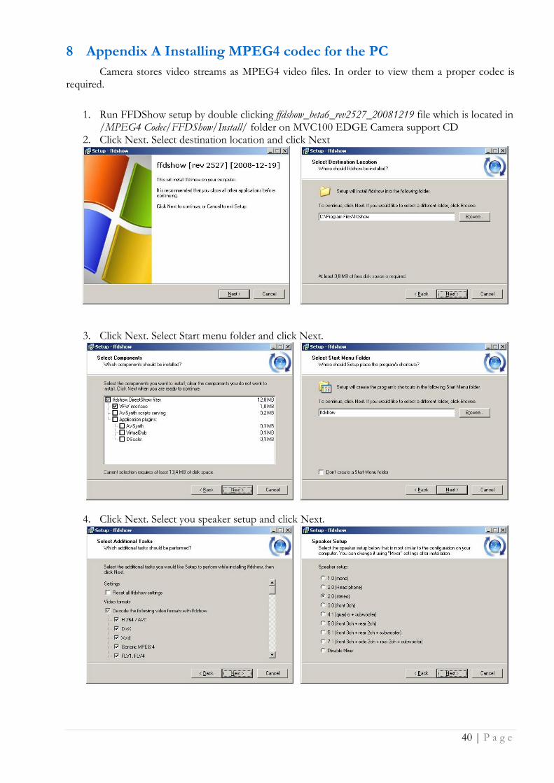
8 Appendix A Installing MPEG4 codec for the PC
Camera stores video streams as MPEG4 video files. In order to view them a proper codec is required.
1. Run FFDShow setup by double clicking ffdshow_beta6_rev2527_20081219 file which is located in /MPEG4 Codec/FFDShow/Install/ folder on MVC100 EDGE Camera support CD
2. Click Next. Select destination location and click Next
3. Click Next. Select Start menu folder and click Next.
4. Click Next. Select you speaker setup and click Next.

41 | P a g e
5. Review Your selections and click Install and click Finish.