Embed Size (px)
Citation preview

Multidisciplinary Senior Design ConferenceKate Gleason College of Engineering
Rochester Institute of TechnologyRochester, New York 14623
Project Number: P16229 & P16029
RoboFish 3.1 Autonomous Navigation with Obstacle Avoidance and Object Retrieval
Duc Jonathan Nguyen
Electrical Engineering
Ryan Wade SelbyElectrical
Engineering
Corey MuenchElectrical
Engineering
Khalfan AlzaabiMechanical Engineering
Matthew YapMechanical Engineering
Nicholas GulatiBiomedical Engineering
Steven SmithMechanical Engineering
Matthew HubeMechanical Engineering
Matthew BalleriniMechanical Engineering
Tae-Ho KangElectrical
EngineeringTyler DaoElectrical
Engineering
Jessa DermittBiomedical Engineering
Denis DiMartinoBiomedical Engineering
Abstract
This project makes use of McKibben muscles, a primarily pneumatic artificial muscle system, to power the locomotion of a biomimetic robotic fish platform. The muscles will be used in a hydraulic scheme. The objective of team P16229 of RoboFish 3.1 was the development of an autonomous system capable of avoiding hazardous. P16229 will work with P16029 to build upon the code to implement a retrieval algorithm, which will catch an object as it falls through the water. The use of a webcam with color image detection allows RoboFish to determine when avoidance algorithm should be implemented. An ultrasonic sensor allows RoboFish to determine when collision with a “wall” is imminent and implement an avoidance algorithm. Solenoid valves control the access of water into the McKibben muscle system, which will then contract and extend mimicking a muscle to produce locomotion. A Raspberry Pi microcontroller handles the image processing while the Arduino Mega 2560 R3 controls the muscle systems and other sensors.
Introduction
RoboFish 3.1 began as the third iteration of the RoboFish design problem. On further analysis of the previous fish design, new designs were suggested and a new fish was then implemented.

P14029 was a design to create a robotic fish that would mimic body caudal fin locomotion and be controlled by a wireless controller. P15029 would maintain the wireless controlling but develop an active buoyancy system. P15029 also had a goal of an autonomous swimming mode but was never completed.
The past designs had an operational time of 1.5 hours maximum and only controlled by a controller. It was also un-aesthetically pleasing and marginally resembled a fish.
Design Process
RoboFish is required to use McKibben muscles to power its body caudal fin locomotion. The McKibben muscles will still use water from its environment to function. This device will be entirely autonomous for an operational time of 5 hours. RoboFish will avoid obstacles using a webcam and image detection to avoid surface objects of a certain color. A Raspberry Pi microcontroller will manage all the image processing and send a digital output to the Arduino microcontroller that will then implement avoidance or catching algorithm. An ultrasonic sensor will be attached to the Arduino to detect a wall surface to avoid a collision. The budget for this project was initially $750 per team but was later increased to $1050 per team due to the cost of batteries and redesign of fish body materials. RoboFish must be able capable of basic forward locomotion, depth control and turning motion. The device must be built robustly so as to require minimal maintenance.
Figure 1: Conceptual RoboFish Design
2

Electrical Systems
RoboFish operates on a 32v battery pack using 36 18650-battery cells. The system functions using 3 team designed boards in conjunction with an Arduino and Raspberry Pi microcontroller.
Figure: Electronic Electrical System Schematic
Arduino Mega 2560 R3
An Arduino Mega 2560 microcontroller was designated to control all valve operation and miscellaneous sensors. The microcontroller was chosen over the UNO version due to having an abundance supply of I/O ports that would be utilized in the design. The Mega also has a larger memory capacity allowing for future expandability of the system.
Raspberry Pi 3 Model B
The Raspberry Pi microcontroller is instrumental in handling the entire image processing from the camera. The microcontroller will analyze an object based on color and based on what
3

quadrant of the camera the object is in will send a digital output to the Arduino to implement a turning algorithm. The Pi will also assist in determining if RoboFish needs to dive or rise in depth.
Battery System
Previous of RoboFish used 2, Zippy 11.1V 5000mAh Li-Po batteries which provided a theoretical operational run time of 1 hour 45 minutes. To meet the new operational run time goal of 5 hours either more batteries needed to be ordered or new options would be explored. After determining that additional Zippy Li-Po battery packs would take up too much surface area, 18650 lithium-ion battery cells were then examined.
Figure: 18650 Battery
The advantage to switching to 18650 cells was that a holster existed that would make a battery pack easily customizable depending on the battery enclosure. Small single battery holsters are used in order to make a customized battery pack shape for the space available in the waterproof enclosure.
Figure: Single Battery Holster
The choice of holsters allows an easier charging situation using commercial chargers thus eliminating the need for a battery management system.
4

Figure 3: Commercial charger Used
It was determined that 36 batteries in a configuration of 9 cells in series in 4 parallel packs would provide the power needed to operate for 5 continuous hours.
Initially during the design phase small sample quantities of UltraFire 18650 batteries were ordered to test due to the cost. The result was that UltraFire batteries did not perform to their advertised rating. In turn the call to purchase much more expensive but quality batteries were made due to the importance of the system. Panasonic batteries were ordered and tested. A pack of 9 batteries in series was tested to act as 1 pack out of 4 and the following figure reveals that the batteries would theoretically be able to power RoboFish for a little over 5 hours.
Figure 2: Panasonic 18650 Energy Testing
5

PCB Design
3 different PCBs were used in the construction of RoboFish. 2 gate drive boards were created each capable of driving 6 solenoid valves. Optocouplers were utilized as a precaution to ensure that the low powered microcontroller was separate from the high voltage gate drive circuitry. 1 interface board was created to convert the battery pack voltage to 24v for use by the solenoid valves and 5v for the Arduino and Pi boards.
Later in the design, in the thought of safety and additional I/O board was created to have a centralized point of connection and convenience of wiring. An important aspect of that board was the available surface space for mounting of a 24v Buck Converter and it’s unique shape to allow access to terminal blocks from the board mounted beneath it.
Eagle PCB design software was used to construct the PCB layout and then sent out to OSH Park for fabrication. OSH Park created 4 layer boards consisting of FR408 substrate, 5 mil trace width, 10 mil drill size, and 4 mil annular ring.
Figure : Gate Drive Circuit Schematic
6

Figure: Gate Drive board (left), I/O Board (right)
Image Processing
The image processing utilized by the system used a USB webcam connected to a raspberry pi. This allows for the fish to both detect a sinking object and to identify the buoys it is required to avoid. The camera would recognize the objects based on their color. The image that the camera receives and then sends to the raspberry pi is transformed from a standard RGB color space to an HSV color space. The HSV color space made it easier to isolate a single color within the frame of the image, by identifying colors primarily on the hue versus the values of red, green, and blue in the image. Once the program recognizes the isolated color, it then identified the shape of the object, and then it measures the width of the object in pixels. Based on prior testing, the width of the object in pixels is then run through an algorithm that knew the relation between pixel width and distance to determine the distance the object is from the fish.
When the fish attempts to catch a sinking object the image processing is used for both determining the distance as well as the vertical position of the object. Taking the frame that the camera sends to the raspberry pi, and dividing it into seven zones determine the vertical position of the object. Each zone has a height of seventy pixels, except for the middle/neutral zone, which has a pixel height of sixty pixels. Each of the heights has a binary value given to them, with 001 starting at the lowest zone, and 111 being the value for the highest zone. The values are then sent to the Arduino, which is controlling the swimming of the fish. The binary value is sent to the Arduino using a serial connection comprised of three different I/O pins. Each
7

pin is assigned a specific bit of the value, and sent to three I/O pins on the Arduino. Additionally, once the camera recognizes that the object has reached a predetermined location it will tell the jaw to open to retrieve the object. For the fish to move to the left and right the same process used for the vertical position is used for the horizontal position. But, for the horizontal the frame is split only into three zones for the left, right, and middle. Similar to the vertical though, left and right each have a status bit which are communicated through the I/O pins of the Raspberry Pi to I/O pins of the Arduino. The status bits for the left and right are simply a one if it is in the specified region, or zero if otherwise.
While the fish is avoiding buoys at the surface, the image processing will identify the objects and their distances. It will do this in a similar fashion when the fish is trying to catch a sinking object, except that the height component is no longer needed. Also, it will be tracking the distance of the object to avoid it instead of go towards it. When the camera detects an object and the program chooses to go either left or right, the same status bits utilized for left and right in the object retrieval will be used for the avoidance. Utilizing the same I/O pins on the Raspberry Pi, and the same two I/O pins on the Arduino, similarly it will be using the same three-zone split as the retrieval process as well.
Locomotion Methodology
Similar to the previous iteration of the RoboFish the team elected to employ caudal fin locomotion as the swimming method. A particular form of undulatory motion, body caudal locomotion (BCL) involves lateral displacement of some part of the body through the water to generate thrust. BCL can be further defined into 5 categories depending on the fraction of the body, which is used to generate thrust, which directly correlates to maneuverability and speed. There happens to be an inverse relationship between speed and maneuverability.
The RoboFish needed to be sufficiently fast so as to be able to reach an object falling through the water. Additionally, the RoboFish needs to be maneuverable enough to dodge buoys, the wall of the tank, and any other obstacles that may block its path. As a result of this we had to carefully select the proper model as so to balance speed and maneuverability. We chose to model the fish after the Carp, which employs something between the carangiform and subcarangiform method of locomotion.
The Carp oscillates the back third to half of its body to generate thrust and maintains a fairly rigid front section. Its body has a high aspect ratio to counteract the lateral motion caused by the actuating tail. We felt that this locomotion method would allow the RoboFish to meet the desired objectives of both our team and the object retrieval team.
Tail Hardware
In order to achieve the oscillatory motion the tail was constructed in two pieces, which are able to rotate with respect to one another and the first section of which is able to rotate with respect to the body. The tail actuates by first redirecting the tip of the tail, using the muscles in
8

the second half, so that it is facing opposite the direction of tail member motion and then by moving the whole tail member, using the muscles in the front half. This action generates trust as a component of the reaction force on the second half of the tail is in the forward direction. The other component of the aforementioned force is a lateral force and the high aspect ratio of the fish in combination with the symmetry of motion is expected to offset this.
Swimming Algorithm
The integration of the subsystems works as follows: the fish swims by a series of signals coming from the Arduino going to the three-way valves that regulate the flow of water into the muscles. The timing of these signals was optimized to generate forward thrust with minimal lateral motion. Upon receiving a signal from the image-processing component, controlled by the Raspberry Pi, the fish implements a turning algorithm wherein the timings are changed. This algorithm locks the tail in either the far left or far right position and then “flaps” the second half of the tail back and forth, leveraging the crescent configuration of the body to turn. The wall is detected using an ultrasonic range finder which implements the same signal, as does the image processing.
Hydraulic System
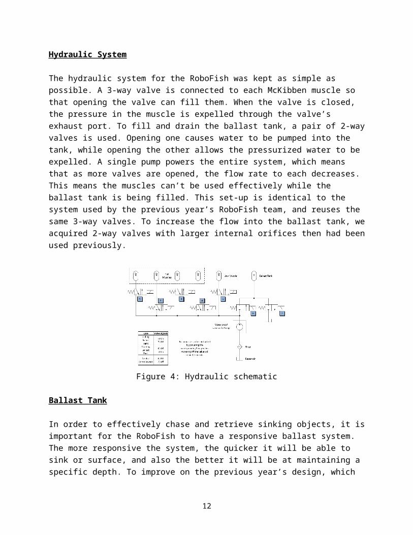
The hydraulic system for the RoboFish was kept as simple as possible. A 3-way valve is connected to each McKibben muscle so that opening the valve can fill them. When the valve is closed, the pressure in the muscle is expelled through the valve’s exhaust port. To fill and drain the ballast tank, a pair of 2-way valves is used. Opening one causes water to be pumped into the tank, while opening the other allows the pressurized water to be expelled. A single pump powers the entire system, which means that as more valves are opened, the flow rate to each decreases. This means the muscles can’t be used effectively while the ballast tank is being filled. This set-up is identical to the system used by the previous year’s RoboFish team, and reuses the same 3-way valves. To increase the flow into the ballast tank, we acquired 2-way valves with larger internal orifices then had been used previously.
Figure 4: Hydraulic schematic
9

Ballast Tank
In order to effectively chase and retrieve sinking objects, it is important for the RoboFish to have a responsive ballast system. The more responsive the system, the quicker it will be able to sink or surface, and also the better it will be at maintaining a specific depth. To improve on the previous year’s design, which used a passively draining ballast tank, a ballast tank with a “pre-charged” air bladder was used. This pressurized bladder increases the initial pressure of the ballast tank, which slightly slows down the rate at which the ballast tank fills, but greatly increases the rate at which water can be expelled from the tank when the RoboFish needs to increase its buoyancy. By using data on the pump performance, valve flow factors, ballast tank volume, and approximations of mass and drag, the speed at which the RoboFish sinks and surfaces can be estimated. By altering the pressure to which the air bladder is pre-charged, the sinking and surfacing rates can be made approximately the same. Using this method we determined the bladder should be pressurized to 10 psi.
To find a desirable ballast tank volume, the expected sinking rate of the diving stick was superimposed on the same estimations. This gives an expected time at which the RoboFish will intercept the sinking diving stick. Varying the ballast tank volume affects the rate at which the RoboFish sinks and produces a graph of interception time versus ballast volume. From this graph we chose a ballast tank size of 0.5 liters to keep the tank as small as possible without suffering large increases in interception time. The ballast tank was constructed from threaded PVC pipe so it could be easily sealed, but could still be disassembled. An inner tire tube for a bicycle was used as the air bladder.
Figure 5: Ballast tank calculations
10

CAD Model
To assist in the design and layout of the RoboFish structure, a CAD model of all the major components was assembled in SolidWorks. In addition to providing technical drawings, the model was also used to approximate the total mass and volume of the RoboFish and the locations of the centers of mass and buoyancy. Because the model predicted the RoboFish would sink, and because the center of mass and buoyancy appeared to be extremely close to each other, we determined we would need to add foam to the top of the RoboFish to increase its buoyancy and stability in the water.
Figure 6: RoboFish center of mass
Figure 7: RoboFish center of buoyancy
11
Fish Skin Design
The skin sheath chosen to overlay the RoboFish is made of spandex. The spandex will be lightly coated in eco-flex and the sheath will be attached with Velcro on the belly of the fish. The main factor to why we chose spandex is because team P15029 successfully used spandex, Velcro, and eco-flex with no problems or complaints. The skin sheath ordered has a fish scales pattern to comply with the requirement of having the RoboFish look fish-like. The reasoning for coating the spandex with eco-flex is to both repel water and to make the material more flexible to adapt to the shape of the fish. The Velcro was an easy and obvious choice to attach to the fish because it is cheap and easy to use. The sheath will be fitted to the fish once all parts and Styrofoam are in place.
Figure: Spandex Skin Sheath with Fish Scale Pattern
Home Navigation
A design requirement was to design an algorithm to allow RoboFish to return to a “home” location. A decision was made to use a Bluetooth sensor to determine the distance of the fish in relation to home. Due to the diffusion of radio waves in water the Bluetooth will not function while the fish is diving or if the sensor is submerged, therefore an extended antenna was attached in order to receive a signal when the RoboFish is on the surface. The extended antenna is located on the top of RoboFish to ensure that the sensor receives a Bluetooth signal.
12

Figure: Bluetooth sensor and Triple Axis Magnetometer
The Bluetooth beacon operates by sending a consistent signal, which allows the receiver to obtain a universally unique identifier (UUID), temperature, and receive a signal strength indicator (RSSI) value from each of the Bluetooth beacons. This will allow RoboFish to determine how far it is from each individual beacon.
Since the RoboFish knows initial compass data and distance to the beacon as well as shortest distance to the beacon and the compass data of it, we can simple use trigonometry to find out what the compass value RoboFish needs to align with in order to reach the Home location. The reason for choosing trigonometry is due to size of operating environment so that the number of Bluetooth beacons needs to be multiplied by at least three which increase budget dramatically.
Figure : Design Diagram of Functioning Theory
Jaw Design The Jaw design was made based on the system for image processing. Essentially, the length and width of the camera used, established the constraints for the extent at which the jaw would open. This measure was done in order to “correct” for the likelihood that the prototype fish would be oscillating in the horizontal direction. That is, to allow for some tolerance for the possibility that the fish would not be in the exact location, but in the general vicinity of the falling object and still have the capabilities of catching the object. The more computational design of the Jaw was the design of a spring to keep the Jaw closed in default. One of the constraints that is addressed in the hydraulic system of this paper, are the limitations behind valves and the pump. So in an effort to use minimal capabilities of the pump for the Jaw, the muscle need only to activate (open) the Jaw when the sensor feeds back to catch the object. Hence the need of a spring to constantly keep the Jaw in close form (default), until the
13

McKibben muscle is activated to open the Jaw. The calculations behind this required knowing the force of the muscle and the implementation scheme to ensure that the force was being fully distributed across the gears into the Jaw.
Figure: CAD Rendering of the Jaw
Results and Discussion
Figure: Final CAD of RoboFish
Conclusions and Recommendations
14

References
[1] P14029. Web. <http://edge.rit.edu/edge/P14029/public/Home>
[2] P15029. Web. <http://edge.rit.edu/edge/P15029/public/Home>
Acknowledgements
This material presented is based upon work supported by Dr. Kathleen Lamkin-Kennard and sponsorship by Boeing. Any opinions, findings and conclusions or recommendation expressed in this material are those of the authors and do not necessarily reflect on third party sources.
15
![Variable stiffness Mckibben muscles with hydraulic and ...usir.salford.ac.uk/37952/10/Variable stiffness Mckibben...to develop a powered lower limb orthosis and Wu et al. [7] developed](https://img.pdfslide.net/doc/110x75/5aae46737f8b9aa8438bd4fa/variable-stiffness-mckibben-muscles-with-hydraulic-and-usir-stiffness-mckibbento.jpg)